US5282121A - High intensity lighting projectors - Google Patents
High intensity lighting projectorsDownload PDFInfo
- Publication number
- US5282121A US5282121AUS07/693,366US69336691AUS5282121AUS 5282121 AUS5282121 AUS 5282121AUS 69336691 AUS69336691 AUS 69336691AUS 5282121 AUS5282121 AUS 5282121A
- Authority
- US
- United States
- Prior art keywords
- light
- array
- pixels
- liquid crystal
- color
- Prior art date
- Legal status (The legal status is an assumption and is not a legal conclusion. Google has not performed a legal analysis and makes no representation as to the accuracy of the status listed.)
- Expired - Lifetime
Links
- 239000004973liquid crystal related substanceSubstances0.000claimsabstractdescription100
- 240000005528Arctium lappaSpecies0.000claimsabstractdescription66
- 239000000463materialSubstances0.000claimsabstractdescription18
- 239000007788liquidSubstances0.000claimsdescription37
- 230000003287optical effectEffects0.000claimsdescription33
- 239000002826coolantSubstances0.000claimsdescription30
- 239000011159matrix materialSubstances0.000claimsdescription23
- 238000000149argon plasma sinteringMethods0.000claimsdescription19
- 230000005540biological transmissionEffects0.000claimsdescription15
- 238000001914filtrationMethods0.000claimsdescription15
- 229920000642polymerPolymers0.000claimsdescription14
- 239000003086colorantSubstances0.000claimsdescription13
- 239000004983Polymer Dispersed Liquid CrystalSubstances0.000claimsdescription12
- 230000000694effectsEffects0.000claimsdescription12
- 239000012530fluidSubstances0.000claimsdescription8
- 239000002131composite materialSubstances0.000claimsdescription6
- 238000005286illuminationMethods0.000claimsdescription6
- 239000004988Nematic liquid crystalSubstances0.000claimsdescription5
- 230000004087circulationEffects0.000claimsdescription4
- 230000002441reversible effectEffects0.000claimsdescription3
- 238000012546transferMethods0.000claimsdescription3
- 229920000106Liquid crystal polymerPolymers0.000claimsdescription2
- 239000004977Liquid-crystal polymers (LCPs)Substances0.000claimsdescription2
- 239000012528membraneSubstances0.000claims2
- 238000001816coolingMethods0.000abstractdescription16
- 230000000007visual effectEffects0.000abstractdescription6
- 230000031700light absorptionEffects0.000abstractdescription2
- 230000000153supplemental effectEffects0.000abstract1
- 238000000034methodMethods0.000description33
- 238000003491arrayMethods0.000description14
- 230000010287polarizationEffects0.000description11
- 238000010521absorption reactionMethods0.000description10
- 238000000576coating methodMethods0.000description9
- 239000011248coating agentSubstances0.000description8
- 230000008569processEffects0.000description8
- 230000007246mechanismEffects0.000description7
- XLYOFNOQVPJJNP-UHFFFAOYSA-NwaterSubstancesOXLYOFNOQVPJJNP-UHFFFAOYSA-N0.000description7
- LYCAIKOWRPUZTN-UHFFFAOYSA-NEthylene glycolChemical compoundOCCOLYCAIKOWRPUZTN-UHFFFAOYSA-N0.000description6
- 230000008901benefitEffects0.000description6
- 230000008859changeEffects0.000description6
- 238000002310reflectometryMethods0.000description6
- 238000013461designMethods0.000description5
- 239000011521glassSubstances0.000description5
- 230000003595spectral effectEffects0.000description5
- 230000033001locomotionEffects0.000description4
- 238000004519manufacturing processMethods0.000description4
- 238000001228spectrumMethods0.000description4
- 230000000712assemblyEffects0.000description3
- 238000000429assemblyMethods0.000description3
- 230000000903blocking effectEffects0.000description3
- 230000006378damageEffects0.000description3
- 238000006073displacement reactionMethods0.000description3
- 238000010348incorporationMethods0.000description3
- 239000000203mixtureSubstances0.000description3
- 230000002093peripheral effectEffects0.000description3
- 230000002829reductive effectEffects0.000description3
- 230000003068static effectEffects0.000description3
- 239000000758substrateSubstances0.000description3
- 239000010409thin filmSubstances0.000description3
- 238000002835absorbanceMethods0.000description2
- 239000006117anti-reflective coatingSubstances0.000description2
- 238000013459approachMethods0.000description2
- 230000003247decreasing effectEffects0.000description2
- 238000001514detection methodMethods0.000description2
- 239000003989dielectric materialSubstances0.000description2
- 230000005684electric fieldEffects0.000description2
- 238000005516engineering processMethods0.000description2
- 230000007613environmental effectEffects0.000description2
- 230000005284excitationEffects0.000description2
- 230000006870functionEffects0.000description2
- 235000021384green leafy vegetablesNutrition0.000description2
- 238000010438heat treatmentMethods0.000description2
- 238000003384imaging methodMethods0.000description2
- 238000012545processingMethods0.000description2
- 230000005855radiationEffects0.000description2
- 230000004044responseEffects0.000description2
- 239000004986Cholesteric liquid crystals (ChLC)Substances0.000description1
- 235000011449RosaNutrition0.000description1
- VYPSYNLAJGMNEJ-UHFFFAOYSA-NSilicium dioxideChemical compoundO=[Si]=OVYPSYNLAJGMNEJ-UHFFFAOYSA-N0.000description1
- XUIMIQQOPSSXEZ-UHFFFAOYSA-NSiliconChemical compound[Si]XUIMIQQOPSSXEZ-UHFFFAOYSA-N0.000description1
- 244000158209Sorbus ariaSpecies0.000description1
- 235000004494Sorbus ariaNutrition0.000description1
- 208000003443UnconsciousnessDiseases0.000description1
- 230000001133accelerationEffects0.000description1
- 230000004888barrier functionEffects0.000description1
- 230000015572biosynthetic processEffects0.000description1
- 239000002775capsuleSubstances0.000description1
- 238000006243chemical reactionMethods0.000description1
- 230000004456color visionEffects0.000description1
- 238000004040coloringMethods0.000description1
- 230000002301combined effectEffects0.000description1
- 238000004891communicationMethods0.000description1
- 239000012141concentrateSubstances0.000description1
- 238000010276constructionMethods0.000description1
- 239000000356contaminantSubstances0.000description1
- 238000011109contaminationMethods0.000description1
- 230000008602contractionEffects0.000description1
- 239000000110cooling liquidSubstances0.000description1
- 239000013078crystalSubstances0.000description1
- 230000001419dependent effectEffects0.000description1
- 230000001066destructive effectEffects0.000description1
- -1e.g.Substances0.000description1
- 230000001747exhibiting effectEffects0.000description1
- 230000002349favourable effectEffects0.000description1
- 239000005350fused silica glassSubstances0.000description1
- 230000017525heat dissipationEffects0.000description1
- 238000012423maintenanceMethods0.000description1
- 238000005259measurementMethods0.000description1
- 238000012634optical imagingMethods0.000description1
- 238000004091panningMethods0.000description1
- 238000005191phase separationMethods0.000description1
- 229920006254polymer filmPolymers0.000description1
- 230000000135prohibitive effectEffects0.000description1
- 238000005096rolling processMethods0.000description1
- 229910052710siliconInorganic materials0.000description1
- 239000010703siliconSubstances0.000description1
- 229920002379silicone rubberPolymers0.000description1
- 238000009987spinningMethods0.000description1
- 201000009032substance abuseDiseases0.000description1
- 230000003685thermal hair damageEffects0.000description1
- 230000007704transitionEffects0.000description1
- 229910021642ultra pure waterInorganic materials0.000description1
- 239000012498ultrapure waterSubstances0.000description1
- 239000013598vectorSubstances0.000description1
- 238000001429visible spectrumMethods0.000description1
Images


Classifications
- F—MECHANICAL ENGINEERING; LIGHTING; HEATING; WEAPONS; BLASTING
- F21—LIGHTING
- F21S—NON-PORTABLE LIGHTING DEVICES; SYSTEMS THEREOF; VEHICLE LIGHTING DEVICES SPECIALLY ADAPTED FOR VEHICLE EXTERIORS
- F21S10/00—Lighting devices or systems producing a varying lighting effect
- F21S10/007—Lighting devices or systems producing a varying lighting effect using rotating transparent or colored disks, e.g. gobo wheels
- F—MECHANICAL ENGINEERING; LIGHTING; HEATING; WEAPONS; BLASTING
- F21—LIGHTING
- F21S—NON-PORTABLE LIGHTING DEVICES; SYSTEMS THEREOF; VEHICLE LIGHTING DEVICES SPECIALLY ADAPTED FOR VEHICLE EXTERIORS
- F21S45/00—Arrangements within vehicle lighting devices specially adapted for vehicle exteriors, for purposes other than emission or distribution of light
- F21S45/40—Cooling of lighting devices
- F21S45/42—Forced cooling
- F21S45/46—Forced cooling using liquid
- F—MECHANICAL ENGINEERING; LIGHTING; HEATING; WEAPONS; BLASTING
- F21—LIGHTING
- F21V—FUNCTIONAL FEATURES OR DETAILS OF LIGHTING DEVICES OR SYSTEMS THEREOF; STRUCTURAL COMBINATIONS OF LIGHTING DEVICES WITH OTHER ARTICLES, NOT OTHERWISE PROVIDED FOR
- F21V14/00—Controlling the distribution of the light emitted by adjustment of elements
- F21V14/003—Controlling the distribution of the light emitted by adjustment of elements by interposition of elements with electrically controlled variable light transmissivity, e.g. liquid crystal elements or electrochromic devices
- F—MECHANICAL ENGINEERING; LIGHTING; HEATING; WEAPONS; BLASTING
- F21—LIGHTING
- F21V—FUNCTIONAL FEATURES OR DETAILS OF LIGHTING DEVICES OR SYSTEMS THEREOF; STRUCTURAL COMBINATIONS OF LIGHTING DEVICES WITH OTHER ARTICLES, NOT OTHERWISE PROVIDED FOR
- F21V29/00—Protecting lighting devices from thermal damage; Cooling or heating arrangements specially adapted for lighting devices or systems
- F21V29/50—Cooling arrangements
- F21V29/56—Cooling arrangements using liquid coolants
- F—MECHANICAL ENGINEERING; LIGHTING; HEATING; WEAPONS; BLASTING
- F21—LIGHTING
- F21V—FUNCTIONAL FEATURES OR DETAILS OF LIGHTING DEVICES OR SYSTEMS THEREOF; STRUCTURAL COMBINATIONS OF LIGHTING DEVICES WITH OTHER ARTICLES, NOT OTHERWISE PROVIDED FOR
- F21V29/00—Protecting lighting devices from thermal damage; Cooling or heating arrangements specially adapted for lighting devices or systems
- F21V29/50—Cooling arrangements
- F21V29/70—Cooling arrangements characterised by passive heat-dissipating elements, e.g. heat-sinks
- F—MECHANICAL ENGINEERING; LIGHTING; HEATING; WEAPONS; BLASTING
- F21—LIGHTING
- F21V—FUNCTIONAL FEATURES OR DETAILS OF LIGHTING DEVICES OR SYSTEMS THEREOF; STRUCTURAL COMBINATIONS OF LIGHTING DEVICES WITH OTHER ARTICLES, NOT OTHERWISE PROVIDED FOR
- F21V9/00—Elements for modifying spectral properties, polarisation or intensity of the light emitted, e.g. filters
- F21V9/04—Elements for modifying spectral properties, polarisation or intensity of the light emitted, e.g. filters for filtering out infrared radiation
- F—MECHANICAL ENGINEERING; LIGHTING; HEATING; WEAPONS; BLASTING
- F21—LIGHTING
- F21V—FUNCTIONAL FEATURES OR DETAILS OF LIGHTING DEVICES OR SYSTEMS THEREOF; STRUCTURAL COMBINATIONS OF LIGHTING DEVICES WITH OTHER ARTICLES, NOT OTHERWISE PROVIDED FOR
- F21V9/00—Elements for modifying spectral properties, polarisation or intensity of the light emitted, e.g. filters
- F21V9/40—Elements for modifying spectral properties, polarisation or intensity of the light emitted, e.g. filters with provision for controlling spectral properties, e.g. colour, or intensity
- G—PHYSICS
- G02—OPTICS
- G02F—OPTICAL DEVICES OR ARRANGEMENTS FOR THE CONTROL OF LIGHT BY MODIFICATION OF THE OPTICAL PROPERTIES OF THE MEDIA OF THE ELEMENTS INVOLVED THEREIN; NON-LINEAR OPTICS; FREQUENCY-CHANGING OF LIGHT; OPTICAL LOGIC ELEMENTS; OPTICAL ANALOGUE/DIGITAL CONVERTERS
- G02F1/00—Devices or arrangements for the control of the intensity, colour, phase, polarisation or direction of light arriving from an independent light source, e.g. switching, gating or modulating; Non-linear optics
- G02F1/01—Devices or arrangements for the control of the intensity, colour, phase, polarisation or direction of light arriving from an independent light source, e.g. switching, gating or modulating; Non-linear optics for the control of the intensity, phase, polarisation or colour
- G02F1/13—Devices or arrangements for the control of the intensity, colour, phase, polarisation or direction of light arriving from an independent light source, e.g. switching, gating or modulating; Non-linear optics for the control of the intensity, phase, polarisation or colour based on liquid crystals, e.g. single liquid crystal display cells
- G02F1/133—Constructional arrangements; Operation of liquid crystal cells; Circuit arrangements
- G02F1/1333—Constructional arrangements; Manufacturing methods
- G02F1/133382—Heating or cooling of liquid crystal cells other than for activation, e.g. circuits or arrangements for temperature control, stabilisation or uniform distribution over the cell
- G02F1/133385—Heating or cooling of liquid crystal cells other than for activation, e.g. circuits or arrangements for temperature control, stabilisation or uniform distribution over the cell with cooling means, e.g. fans
- G—PHYSICS
- G03—PHOTOGRAPHY; CINEMATOGRAPHY; ANALOGOUS TECHNIQUES USING WAVES OTHER THAN OPTICAL WAVES; ELECTROGRAPHY; HOLOGRAPHY
- G03B—APPARATUS OR ARRANGEMENTS FOR TAKING PHOTOGRAPHS OR FOR PROJECTING OR VIEWING THEM; APPARATUS OR ARRANGEMENTS EMPLOYING ANALOGOUS TECHNIQUES USING WAVES OTHER THAN OPTICAL WAVES; ACCESSORIES THEREFOR
- G03B21/00—Projectors or projection-type viewers; Accessories therefor
- G03B21/14—Details
- G03B21/16—Cooling; Preventing overheating
- H—ELECTRICITY
- H04—ELECTRIC COMMUNICATION TECHNIQUE
- H04N—PICTORIAL COMMUNICATION, e.g. TELEVISION
- H04N5/00—Details of television systems
- H04N5/74—Projection arrangements for image reproduction, e.g. using eidophor
- H04N5/7416—Projection arrangements for image reproduction, e.g. using eidophor involving the use of a spatial light modulator, e.g. a light valve, controlled by a video signal
- H04N5/7441—Projection arrangements for image reproduction, e.g. using eidophor involving the use of a spatial light modulator, e.g. a light valve, controlled by a video signal the modulator being an array of liquid crystal cells
- H—ELECTRICITY
- H04—ELECTRIC COMMUNICATION TECHNIQUE
- H04N—PICTORIAL COMMUNICATION, e.g. TELEVISION
- H04N9/00—Details of colour television systems
- H04N9/12—Picture reproducers
- H04N9/31—Projection devices for colour picture display, e.g. using electronic spatial light modulators [ESLM]
- H04N9/3102—Projection devices for colour picture display, e.g. using electronic spatial light modulators [ESLM] using two-dimensional electronic spatial light modulators
- H04N9/3111—Projection devices for colour picture display, e.g. using electronic spatial light modulators [ESLM] using two-dimensional electronic spatial light modulators for displaying the colours sequentially, e.g. by using sequentially activated light sources
- H04N9/3114—Projection devices for colour picture display, e.g. using electronic spatial light modulators [ESLM] using two-dimensional electronic spatial light modulators for displaying the colours sequentially, e.g. by using sequentially activated light sources by using a sequential colour filter producing one colour at a time
- H—ELECTRICITY
- H04—ELECTRIC COMMUNICATION TECHNIQUE
- H04N—PICTORIAL COMMUNICATION, e.g. TELEVISION
- H04N9/00—Details of colour television systems
- H04N9/12—Picture reproducers
- H04N9/31—Projection devices for colour picture display, e.g. using electronic spatial light modulators [ESLM]
- H04N9/3141—Constructional details thereof
- H04N9/3144—Cooling systems
- H—ELECTRICITY
- H04—ELECTRIC COMMUNICATION TECHNIQUE
- H04N—PICTORIAL COMMUNICATION, e.g. TELEVISION
- H04N9/00—Details of colour television systems
- H04N9/12—Picture reproducers
- H04N9/31—Projection devices for colour picture display, e.g. using electronic spatial light modulators [ESLM]
- H04N9/3141—Constructional details thereof
- H04N9/315—Modulator illumination systems
- H04N9/3155—Modulator illumination systems for controlling the light source
- H—ELECTRICITY
- H04—ELECTRIC COMMUNICATION TECHNIQUE
- H04N—PICTORIAL COMMUNICATION, e.g. TELEVISION
- H04N9/00—Details of colour television systems
- H04N9/12—Picture reproducers
- H04N9/31—Projection devices for colour picture display, e.g. using electronic spatial light modulators [ESLM]
- H04N9/3197—Projection devices for colour picture display, e.g. using electronic spatial light modulators [ESLM] using light modulating optical valves
- F—MECHANICAL ENGINEERING; LIGHTING; HEATING; WEAPONS; BLASTING
- F21—LIGHTING
- F21W—INDEXING SCHEME ASSOCIATED WITH SUBCLASSES F21K, F21L, F21S and F21V, RELATING TO USES OR APPLICATIONS OF LIGHTING DEVICES OR SYSTEMS
- F21W2131/00—Use or application of lighting devices or systems not provided for in codes F21W2102/00-F21W2121/00
- F21W2131/40—Lighting for industrial, commercial, recreational or military use
- F21W2131/406—Lighting for industrial, commercial, recreational or military use for theatres, stages or film studios
- G—PHYSICS
- G02—OPTICS
- G02F—OPTICAL DEVICES OR ARRANGEMENTS FOR THE CONTROL OF LIGHT BY MODIFICATION OF THE OPTICAL PROPERTIES OF THE MEDIA OF THE ELEMENTS INVOLVED THEREIN; NON-LINEAR OPTICS; FREQUENCY-CHANGING OF LIGHT; OPTICAL LOGIC ELEMENTS; OPTICAL ANALOGUE/DIGITAL CONVERTERS
- G02F1/00—Devices or arrangements for the control of the intensity, colour, phase, polarisation or direction of light arriving from an independent light source, e.g. switching, gating or modulating; Non-linear optics
- G02F1/01—Devices or arrangements for the control of the intensity, colour, phase, polarisation or direction of light arriving from an independent light source, e.g. switching, gating or modulating; Non-linear optics for the control of the intensity, phase, polarisation or colour
- G02F1/13—Devices or arrangements for the control of the intensity, colour, phase, polarisation or direction of light arriving from an independent light source, e.g. switching, gating or modulating; Non-linear optics for the control of the intensity, phase, polarisation or colour based on liquid crystals, e.g. single liquid crystal display cells
- G02F1/133—Constructional arrangements; Operation of liquid crystal cells; Circuit arrangements
- G02F1/1333—Constructional arrangements; Manufacturing methods
- G02F1/1334—Constructional arrangements; Manufacturing methods based on polymer dispersed liquid crystals, e.g. microencapsulated liquid crystals
- G—PHYSICS
- G02—OPTICS
- G02F—OPTICAL DEVICES OR ARRANGEMENTS FOR THE CONTROL OF LIGHT BY MODIFICATION OF THE OPTICAL PROPERTIES OF THE MEDIA OF THE ELEMENTS INVOLVED THEREIN; NON-LINEAR OPTICS; FREQUENCY-CHANGING OF LIGHT; OPTICAL LOGIC ELEMENTS; OPTICAL ANALOGUE/DIGITAL CONVERTERS
- G02F1/00—Devices or arrangements for the control of the intensity, colour, phase, polarisation or direction of light arriving from an independent light source, e.g. switching, gating or modulating; Non-linear optics
- G02F1/01—Devices or arrangements for the control of the intensity, colour, phase, polarisation or direction of light arriving from an independent light source, e.g. switching, gating or modulating; Non-linear optics for the control of the intensity, phase, polarisation or colour
- G02F1/13—Devices or arrangements for the control of the intensity, colour, phase, polarisation or direction of light arriving from an independent light source, e.g. switching, gating or modulating; Non-linear optics for the control of the intensity, phase, polarisation or colour based on liquid crystals, e.g. single liquid crystal display cells
- G02F1/133—Constructional arrangements; Operation of liquid crystal cells; Circuit arrangements
- G02F1/1333—Constructional arrangements; Manufacturing methods
- G02F1/1335—Structural association of cells with optical devices, e.g. polarisers or reflectors
- G02F1/133509—Filters, e.g. light shielding masks
Definitions
- the present inventionrelates to light projectors used for various illumination and lighting applications and in particular to projectors that are used to obtain visual effects, light pattern generation and projection in stage illumination and in architectural, display and similar applications.
- Lighting projectorse.g., those used in stage lighting, are typically equipped with one or more control devices for controlling intensity or focusing or dimensioning the beam, changing its color, or changing the beam's direction.
- Modern multiple parameter (automated) projectorsinclude controls for all of these parameters and more.
- a number of lighting control applicationscall for controllable beam shapes and patterns. Performance lighting in stage productions, for example, often requires a variety of different beam patterns and/or shapes.
- a projection gateis often used to form the desired image across the beam of light.
- the projection gatesare embodied as shutters or etched masks that function like stencils in the beam path to project a particular beam configuration.
- Known arrangements, "gobos" for exampleoften include rotary assemblies that incorporate several pattern generating elements encircling the axis of rotation, along with a drive mechanism for rotating a selected pattern into the beam path.
- Arrays of liquid crystal pixelsare potentially useful as projection gates because of their electro-optic effect, and because a virtually unlimited number of high resolution images may theoretically be synthesized quickly and easily.
- Such liquid crystal arrayscan be used to create images by selectively placing each individual pixel of the array in a relaxed (light blocking) state, or in an aligned (light transmitting) state, or in a state intermediate between the two extreme positions according to a "grey scale". Selection of a grey level may be obtained by controlling the voltage or other control stimuli that is applied to the pixel, thus controlling the alignment or transmissivity of the associated liquid crystals. Over certain ranges there is a predictable relationship between the applied control stimulus and the extent of alignment among the liquid crystals in the pixels, thus providing grey scale control. Whether used in this manner or in a two-state, on-off mode, pixellated liquid crystal arrays have the potential to be used in a "light valve" capacity to create a complete picture across a beam of light.
- Pixels in an array of liquid crystalsmay be relatively densely packed thus offering opportunities for higher resolution and transmission efficiency. Also, they may be individually controlled by a addressing scheme capable of selectively placing each pixel of the array in a desired state. Thus a virtually limitless range of images may be rapidly varied. In many applications pixels are arranged in a row and column configuration and activated by applying a potential to a particular control element associated with each of the pixels. Alternatively, a multiplex or other addressing scheme can be employed to reduce the number of elements necessary to address the pixels. Both active and passive matrices may be utilized.
- TNLCtwisted nematic liquid crystal
- the disclosed polarization methoduses a polarization convertor consisting of a polarizing beam splitter, a polarization direction rotator and a synthesizer to significantly improve the illumination efficiency.
- the polarizing beam splitterseparates the incident light into two mutually perpendicular linearly polarized beams (transmitted p-polarized light and reflected s-polarized light).
- the polarization direction rotatoreffectively recaptures much of the light that was lost in previous polarizing systems by rotating the polarization direction of the p-polarized light ninety degrees to equalize both polarization directions. Thereafter, the two components of the light are combined on the liquid crystal by the synthesizer.
- the polarization convertormay ultimately provide a conversion efficiency approaching 100%.
- Cooling by forced airis thought to be effective in some applications because it is theoretically transparent to incident light and does not reduce the amount of transmission. Unfortunately however, heat dissipation techniques which depend on fan operation and other forced air cooling techniques can create noise levels which make this technique unacceptable for many performance and display applications. Air cooling also exposes optical elements to atmospheric contaminants which can compromise optical clarity and cause other problems.
- a multi-layer dielectric interference filterotherwise known as a dichroic "hot mirror"
- a liquid cellplaced in the light path between the light source and the mechanical projection gate to remove energy in the infrared region from the beam of light.
- the hot mirroraids the process of infrared filtering by reflecting "near" infrared energy having wavelengths in the range of about 700 to 1500 nanometers while passing light in other regions.
- the water in the liquid cellis effective in absorbing the "far" infrared energy in the 1.5 to 10 micrometer region that is not reflected by the dichroic filter.
- the water cellis effective because it displays good transmission characteristics for energy having shorter wavelengths (i.e., visible light).
- the combination of the infrared-absorbing liquid cell and the infrared-reflecting "hot mirror”removes infrared radiation from the beam before it reaches the projection gobo. This process reduces the heating effects of the infrared energy and results in an overall increase in the temperature stability of the optical apparatus.
- a second class of liquid crystal devicesis available which will scatter, rather than absorb incident light while in a blocking mode. These scattering liquid crystal arrays thus offer the potential for use in high-intensity projectors having high heat environments.
- light scattering gatesoffer the vitally important property of not requiring pre-polarization of the light incident upon the projection gate. This eliminates a light intensity loss which is prohibitive for many applications.
- Yet another object of the inventionis to provide improved projector cooling techniques that provide more stable thermal environments thereby permitting a broader range of beam control devices to be used in high intensity light projectors. Improved cooling to minimize the potential discomfort that is ordinarily experienced by a performer under bright lights is another object.
- a further object of the inventionis to create innovative and unusual visual lighting effects by jointly and individually utilizing a dynamically variable liquid crystal projection gate and a gobo unit.
- An additional aim of the inventionis to provide a lighting projector that operates in a closed environment, thereby improving reliability, decreasing the risk of contamination and reducing the noise emanating from the system.
- Another goal of the inventionis to provide color control assemblies capable of controlling color parameters in a graduated manner in order to accommodate the special characteristics of human color perception.
- a further object of the inventionis to provide improved color control systems employing feedback supplied by a beam spectrum sensor.
- Another object of the inventionis to provide improved dimming means coupled with an intensity level feedback sensor.
- one aspect of the inventioncomprises a light projection system for lighting applications having one or more light projectors which include image forming means, at least one of the projectors comprising: (1) a light beam source for generating a beam having an intensity suitable for lighting applications; (2) a projection gate located to modulate the beam and having an addressable array of light-scattering liquid crystal pixels capable of assuming transparent and opaque states; (3) a heat management system for protecting the array of liquid crystals from the heat generated by the beam; and (4) a source of image control signals connected to the array to control the states of the pixels to vary the image projected by the beam.
- Another aspect of the inventionfeatures an image projection system comprising: (1) a light beam source for generating a beam; (2) a beam modulation system including an addressable array of light scattering liquid crystal pixels capable of assuming transparent and opaque states; (3) a heat sink for the array comprising a liquid cell in thermally conductive relationship to the array; and (4) a source of image control signals connected to the array to control the states of the pixels to thereby vary the image projected by said beam.
- Yet another aspect of the inventionrelates to color control and contemplates a light projection system for lighting applications having one or more light projectors which include beam color control means, the projectors comprising: (1) a light beam source for generating a beam having an intensity suitable for lighting applications; (2) a set of color filter elements transposable relative to the beam; and (3) certain of the color filter elements comprising variable dichroic filtering materials configured such that filter cutoff and cut-on wavelengths are adjustable by positioning said elements.
- the filter elementsare circular elements in which the hue parameters vary circumferentially and saturation varies in the radial direction.
- rotation through the beamvaries hue while orthogonal movement laterally of the beam axis effects saturation control.
- the color control systemincludes a color responsive feedback element such as a linearly variable band pass filter functioning as a spectrum analyzer which in conjunction with a photodiode array or other suitable transducer, measures beam color and supplies accurate color measurement signals to a color controller. This permits precise color matching among luminaires.
- a color responsive feedback elementsuch as a linearly variable band pass filter functioning as a spectrum analyzer which in conjunction with a photodiode array or other suitable transducer, measures beam color and supplies accurate color measurement signals to a color controller. This permits precise color matching among luminaires.
- gobo selecting meansare combined with gobo orientation control means to produce a selection of gobo effects involving both programmably oriented static patterns and the dynamic rotation of those patterns.
- an intensity control systemincludes an intensity feedback transducer, and a dimming wheel having a spatially-modulated, variable-density, reflective coating applied thereon, cooperating with a local control system to produce specified output intensity levels.
- FIG. 1is a schematic side elevation view of the interior of a light projector showing certain features of the invention
- FIG. 2is a schematic view of a portion of a liquid crystal array illustrating various states of liquid crystal droplets contained in a polymer matrix;
- FIG. 3is a schematic view of an embodiment of a liquid crystal (LC) projection array and an infrared absorbing and conductive cooling liquid cell assembly;
- LCliquid crystal
- FIG. 4is a schematic plan view of a programmable light-scattering, active-matrix projection gate for use in the systems of FIGS. 1 and 7;
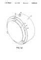
- FIGS. 5 and 5Aare schematic side sectional and perspective views, respectively, of an embodiment of the LC projection array and liquid cell assembly
- FIG. 6is a schematic side sectional view showing an alternate embodiment of a LC projection array and liquid cell assembly
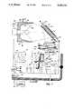
- FIG. 7is a schematic side elevation view of a part of the interior of a light projector showing the preferred optical system thereof;
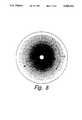
- FIG. 8is a plan schematic view which illustrates one of the color filters forming the color control system of the invention.
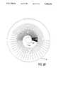
- FIG. 8Ais a plan schematic view which illustrates the dot density of the color filters forming the saturation control system of the invention.
- FIG. 8Bis a plan schematic view which illustrates the spatially-modulated, variable-density, reflectively coated dimming wheel of the invention.
- FIGS. 9A through 9Gcomprise a set of spectral transmission curves illustrating certain properties of the color wheel system of the invention.
- FIG. 10is a schematic plan view of an alternate embodiment of a programmable rotatable gobo wheel assembly.
- a light projector systemincludes a lamp 10 and a reflector 12 that cooperate to focus a beam of light 50 upon a programmable light pattern generator or projection gate 14 containing a liquid crystal array and immersed in a filter/coolant liquid cell 20.
- the light sourcee.g., a high intensity, 1000 Watt arc lamp, emits radiant energy over a band including visible, infrared, and ultraviolet which is then collected by the reflector 12 and directed as a beam of unpolarized focused light 50 to the programmable image generator 14.
- the pixels of the latterare energized via a driver 18 which is controlled in turn by the lighting control system 40 which may be of the type shown in U.S. Pat. No. 4,980,806 to Taylor et al., incorporated herein by reference.
- a multi-layer dielectric interference filter 32may be placed between the projection gate 14 and lamp 10.
- the filter 32incorporates an optical thin film exhibiting dichroic properties that are chosen to reflect near-infrared while transmitting the shorter, visible wavelengths.
- a lens system such as 16is provided to collect the light that is transmitted straight through, and modulated by, the gate 14 and to project the resultant image.
- the programmable light pattern generator 14is comprised of an array of liquid crystal pixels capable of scattering light in one mode and transmitting light in another mode.
- One type of scattering material suitable for such an arrayis nematic liquid crystals dispersed in a polymer matrix. The resultant is referred to as Polymer-Dispersed Liquid Crystals (PDLC).
- PDLCPolymer-Dispersed Liquid Crystals
- NCAPNematic curvilinear aligned phase
- LCPCliquid crystal polymer composites
- NC-LCDnematic-cholesteric liquid crystal diplays
- PN-LCDpolymer network liquid crystal displays
- a TN systemthat reduces ir susceptibility and polarization losses sufficiently, and employs LC systems with appropriate properties, may suffice for some applications.
- Pixel elements comprised of nematic liquid crystals dispersed in a polymer filmcan be individually driven to one of several states. In one state, light incident at a narrow angle about the perpendicular will be transmitted through the pixel element, and will then be collected by the lens system 16 for projection. In another state, transmission of incident light is effectively prevented by utilizing the reflective and refractive properties of light traveling through interfaces with mismatched indices of refraction to scatter the incident light.
- a grey scaleis obtained by placing the liquid crystals in intermediate states of alignment by control of the energizing signal, thus controlling the amount of transmissivity of light straight through the pixel.
- the gate arraycomprises liquid crystal droplets 41 dispersed in a polymer matrix 42, which is positioned between two transparent plates 14a and 14b, containing an active matrix 14e (FIG. 4).
- the control elements 14done for each pixel, each apply the proper drive voltage to its respective pixel 14c from a signal source V.
- the liquid crystal materials used in PDLC arrayshave two indices of refraction, measured along perpendicular axes.
- the extraordinary index of refraction, n eis measured along the liquid crystal's long axis
- the ordinary index of refraction, n ois measured along an axis perpendicular to the axis of n e .
- the polymer matrix containment mediumhas an index of refraction, n p , that is matched to the extraordinary index of refraction, n e .
- incident light I imay be transmitted or scattered depending upon whether the light encounters matched or mismatched indices of refraction as it travels through the interfaces of the polymer matrix/liquid crystal combination.
- the range of index matching in the pixelsis preferred to control the range of index matching in the pixels from an exact degree of matching to a maximum degree of mismatch.
- the lightwill be nearly completely transmitted in one state, partially transmitted in the intermediate states, and dispersed to such an extent in the off state as to put the pixel in an opaque condition.
- the gateit is preferable to design the gate to provide high contrast ratios, e.g., ratios of about 100:1 or greater.
- the composition of the liquid crystal and polymer composite used in the projection gate 14 and the electrical characteristics of the active matrix control elementswill determine the signal (amplitude, frequency and timing), and power requirements of the gate driver system used to vary pixel excitation over a range from transparent through opaque.
- the liquid crystal matrixmust have the proper electrical characteristics so that the voltage drop occurs primarily across the liquid crystal material 41, rather than across the polymer matrix material 42.
- Active matricesare described in many patents and publications. See e.g., U.S. Pat. No. 4,818,981 to Oki et al.
- control parameterscan establish that the picture elements are in a clear state having an ordered alignment (perpendicular transmissive mode) under normal conditions with no energy applied, and in an opaque state having a random alignment (oblique transmissive mode) with the application of the appropriate electrical signal; or vice versa.
- the former type of arrayis known as "reverse mode" and is particularly desirable in applications that require the liquid crystal material to return to a clear state when power is lost.
- Some alternate ways of controlling the alignment of the pixels in an arrayinclude the use of thermal, magnetic or electro-magnetic (including optical) excitation as control stimuli. In particular applications, these methods may be suitable for incorporation as alternate embodiments in order to control the alignment of the liquid crystals.
- the electronic driver circuit 18, FIGS. 1 and 4typically receives a video signal from the lighting controller 40 and selectively energizes individual elements of the array in accordance with the input video pattern by selective application to the appropriate rows and columns, M1 and M2 (FIG. 4), respectively.
- the desired imageis created across the projection gate 14 and modulates the light beam which is then collected and projected by the lens system 16.
- video framesmay be stored as cues, e.g., locally in the lamp, and supplied as directed to the gate to produce animated and real-time type imaging.
- a single framecan also be manipulated through processing to produce multiple variations.
- a video communication linkcan be employed to supply continuous video from a remote source.
- the driver circuit 18preferably accepts video signals that are represented by digital logic control signals, which are transmitted either serially or in parallel, and is typically designed as a microprocessor-compatible peripheral device meeting the interface requirements of the liquid crystal array 14.
- the gate elementsmay be arranged in various configurations, e.g., in a 100 ⁇ 100 element array containing 10,000 individual pixels and the associated electrical connections for application of the drive signal to each.
- 200 electrical connectionscould be used to access each of the pixels in a 100 ⁇ 100 element array by way of the associated active element. In this manner, the image data can be sent down the columns in order to activate the desired pixels activated row by row.
- Active matricesare obtainable from Optical Imaging Systems of Troy, Mich. Specific driver designs will depend on the characteristics of the gate. For illustrative features see e.g., the drivers SED1180F, 1181F, 1190F and 1191F marketed by S-MOS Systems Inc. of San Jose, Calif.
- Plasma addressingis described by Thomas S. Buzak in "A New Active-Matrix Technique Using Plasma Addressing" (S.I.D. 90 Digest pp. 420-423).
- the techniquereplaces the active matrix required to access each pixel with plasma-containing channels and offers a broad drive voltage range with means for accurately placing that voltage at a selected pixel.
- the broad voltage range provided by plasma addressingallows LC materials requiring a large drive voltage to be placed in a selected state according to the desired grey level.
- Plasma addressingsimplifies display fabrications by replacing the conventional TFT control elements (14d) with a selectively conductive channel of confined gas.
- the arrayis therefore comprised of drivers for accessing pixel columns, similar to a conventional addressing scheme, and a plasma channel for each row to latch the column video data.
- the transmissivity of an individual pixelis controlled by applying a data signal to the pixel by means of its column driver and by controlling the conductivity of the gas contained in the associated channel.
- Plasmaa highly conductive ionized gas, completes the electrical circuit between the data line and ground. Thus, the signal on the data column will only excite the liquid crystals in the pixel when the gas is in its conducting, plasma state.
- a preferred embodiment of the present invention for high performance applicationsincludes a 200 ⁇ 200 element PDLC array in an active matrix, the unit being configured as the projection gate of a light projector that is constructed as a three square inch "window". Where more modest imaging performance is acceptable, the gate may comprise an array of 35 ⁇ 35 pixels. Even with this reduced resolution, image variety and speed are markedly superior to mechanically controlled gobos.
- a projection arraycomprised of a liquid crystal and polymer composite is temperature dependent.
- Projection gates formed of this materiale.g., PDLC, offer maximum transmission only for a specific range of temperatures, so maintaining the projection gate within a stable operating temperature range is important.
- the projection unit shown in FIG. 1includes a heat control system which incorporates infrared filtering control mechanisms 20, and 32 to mitigate the rise in temperature and thereby prevent thermal destruction of the optical elements.
- Filtering control mechanism 32also serves to absorb ultraviolet energy that would chemically alter the liquid crystal display.
- the systemFor dealing with long wavelength infrared ("far" infrared) the system includes a liquid filled cell 20 containing water and/or another appropriate fluid such as ethylene glycol. As seen in FIG. 3, the cell is formed of two parallel, spaced transparent walls 22 and 24 orthogonal to the beam axis. Side walls, not shown, and top and bottom plates 24a and 24b complete the enclosure.
- the liquid in cell 20absorbs infrared energy from the beam 50, while providing excellent transmission characteristics at shorter, visible wavelengths.
- Removal of heat from cell 20is accomplished by circulating liquid through cell 20 via an inlet 24c and an outlet 24d, FIG. 3. These are connected in a line 31, FIG. 1, of a thermostatically-controlled liquid circulating system including a pump 25, flow control switch 30 and radiator 26. The latter may preferably be cooled by convection.
- a thermostatically-controlled, low-noise fan 28 located to avoid intrusive noisemay be used for some applications.
- the flow switch 30may also be instrumented to sense the flow of liquid so that, should the pump fail or the system develop a leak, this condition may be sensed and signalled to an attendant. Alternatively, the sensed condition may cause the lamp 10 to be automatically extinguished to protect the array 14 and other optical devices before any thermal problems develop.
- an expansion chambermay be provided as part of the circulation system which can be placed relatively remote from the cell to accommodate hydraulic pressure surges within the liquid system and thereby reduce the risk of leaks.
- the coolant systemwhich may employ ethylene glycol or a mixture of it and water, serves to prevent excessive temperatures in both the filtering liquid cell 20 and in the gate 4 immersed therein.
- a hot mirror 36 on the incident face of the gateprovides additional temperature control.
- the assemblyis also provided with anti-reflective coatings 35 on the interior of front window 22, back window 24 and the liquid interface of gate plate 14b to increase transmission efficiency.
- FIGS. 5 and 5AA preferred embodiment of the gate/liquid cell is shown in FIGS. 5 and 5A. It comprises a first sealed cylindrical chamber 60 for containing the infrared absorbing liquid 64, preferably optically clear ultra-pure water.
- a flanged cylindrical, flexible boot 62preferably of silicon rubber, forms the peripheral boundary of a sealed chamber 60 having end faces formed by transparent front and rear windows 88 and 85.
- the silicon boot 62provides for expansion and contraction as the water chamber volume varies with temperature.
- the front and rear windows 88, 85 of the cell 60, clamped in place with the aid of retainer clips 80,may be comprised of a fused quartz material and are preferably of a minimum thickness consistent with structural needs.
- a second annular chamber 66suitable for containing a coolant 68, and providing for maximum heat transfer between the liquid 64 in the cell 60 and the coolant 68 in chamber 66.
- the coolant chamber 66is defined by the cylindrical boot 62, forming its interior periphery and an outer cylinder 72, with flanges 81, as shown in FIG. 5. This arrangement provides a mechanism for the transfer of heat absorbed by the water 64 from the infrared absorbing process, out of the liquid cell chamber 60 transferred across the boot 62 boundary to the secondary fluid or coolant 68.
- Meansare provided for circulating the coolant 68 through the coolant chamber 66.
- the coolantis circulated through the chamber 66 by means of the input and output channels 65 and 67, the former being connected to the output of a radiator, such as 26, FIG. 1, so that the temperature of the liquid crystal display is maintained.
- the coolantprovides cooling of the projection gate array 79 having a front glass 78 and a rear glass 88. This is achieved by placing the matrix assembly in thermal contact with the liquid in the filtering chamber 60 thus accessing the coolant.
- the rear glass of the projection gatecan be formed as the front window 88 of the liquid cell.
- anti-reflective coatings 87can be placed on the front and rear surfaces of the liquid cell/ projection gate assembly as shown in FIG. 5. This is done to minimize interface mismatches and thus reduce surface reflections as light passes from one medium to another.
- chamber 60 of the liquid cellminimizes turbulence and maintains the transparency of the water to preserve the clarity of an image formed in the beam by the liquid crystal array.
- the liquid subsystemWhen mounted in a panning and tilting head assembly suitable for use as an automated stage lighting instrument, the liquid subsystem will be filled to an extent to maintain the requisite clarity with no appreciable turbulence or bubbles within the cell.
- FIG. 6An alternate embodiment of the gate/cell assembly is shown in FIG. 6. As illustrated, the infrared absorbing liquid is contained in a cylindrical enclosure 110 defined by a cylindrical peripheral wall 115 and transparent, planar front and rear windows 112 and 131. A helical channel is formed in cylindrical wall 115 and is covered by an outer sleeve 123 to define a coolant path 122 having inlet and outlet ports 120 and 121. The resultant coolant flow is designed to provide additional temperature stability.
- an expansion chamber 125Communicating with the chamber 110 is an expansion chamber 125 which includes a duct 133 extending into chamber 110.
- the transparent face 112 of the unitincludes a light scattering array 111 sandwiched between the transparent plates 112 and 113.
- the arraymay be of any of the forms previously described.
- the coolant in chamber 110may be selected such that its index of refraction matches the index associated with the front and rear walls 112 and 131.
- FIG. 7The preferred embodiment of the optical system of the present invention is illustrated in FIG. 7.
- the disclosed "fold back mirror” assemblyoffers several benefits. In addition to solving problems of space constraints, this configuration offers additional surfaces which may be utilized by the infrared and ultraviolet filtering assembly. By applying “cold mirror” coatings to certain of the reflective surfaces, additional infrared energy may be removed from the beam of light.
- the projector lamp assembly 200includes a lamp 201, such as a Phillips MSR series arc lamp, which is energized from a lamp supply 202 controlled via a local processor 285 from the system controller 203.
- a lamp 201such as a Phillips MSR series arc lamp
- These system componentsmay be of the type shown in previously mentioned U.S. Pat. No. 4,980,806.
- the lamp supply 202 and other electronic componentsare cooled via coolant lines 202a and 202b connected to the coolant system.
- Lamp 201is mounted in a reflector assembly 204 having a reflective surface 209 and a coolant chamber 205 with an inlet 206 and outlet 207. Coolant is circulated through the chamber via these ports under control of the coolant system previously described.
- the reflector assemblymay have an exterior cold mirror coating on surface 209 and an infrared absorbing surface applied to the interior distal surfaces 205A and 205B of chamber 205. Infrared light incident on the cold mirror is transmitted through it and is then partially absorbed by the coolant in chamber 205 and partially by the infrared absorbing surface on its walls.
- the beam projected from projection assembly 200is incident on a cold mirror and liquid coolant unit 210 having an interior coolant chamber 211 which is connected to the coolant circulating system via inlet port 212 and outlet port 213.
- the mirrorincludes a glass substrate 216 on which is deposited a multi-layer dielectric interference filter 215, which reflects light in the visible spectrum while passing infrared and ultraviolet wavelengths.
- Infrared energy passing through the filter 215is partially absorbed by the coolant in chamber 211 and partially by the infrared absorbing surface 214 mounted on the back of the mirror assembly. This surface too is the beneficiary of the heat conduction provided by the circulated coolant.
- the ultraviolet energyis absorbed partially by the glass substrate 216.
- the projected beam reflected from mirror unit 210is converged on a color control assembly 221.
- arrays of liquid crystal pixelscan be used to create multi-color projected images, relatively complex multi-path optical systems are normally required. To avoid this expense and complication and some of the tradeoffs it requires, it is preferred to generate a single color beam through the use of dichroic filters and to concentrate the resultant filtered monochromic (single color) light on the projection array. This approach is desirable because the combination of dichroic filter features (discussed in a following section) has been found to yield extraordinary color control.
- the color wheel assembly embodying these featuresincludes three color wheels 220A, 220B and 220C that offer a continuous range of colors around their circumference (see also FIG. 8). Under control of the system controller 203, each of the three wheels may be rotated to a position corresponding to a particular set of color parameters. This permits smooth fades and other continuous variations not achievable in conventional assemblies, including variations in color center (hue) and color band width (saturation) of the light beam.
- Each color wheelcomprises a variable, all dielectric dichroic filter that allows light of particular bands of wavelengths (corresponding to particular colors) to pass while reflecting the light at other wavelengths.
- This variable thickness multi-layer optical thin filmis designed to minimize absorbance and to operate at high optical power densities. Its composition includes layers of dielectric materials having different indices of refraction and thickness, these parameters being varied over the filter surface to produce continuously variable spectral responses.
- the first color wheel 220Amay be a variable short wave pass "edge” filter transmitting light of shorter wavelengths and attenuating light of longer wavelengths. As shown in FIG. 9A, this filter tends to pass light having "blue" wavelengths, and the cut-off wavelength can be variably extended continuously by rotating the wheel to a position having a different, e.g., longer cut-off wavelength such that the edge effectively slides along the wavelength axis, passing light having longer wavelengths (greens and reds).
- the second wheel 220Bmay be a variable long wave pass edge filter transmitting light of longer wavelengths and attenuating light of shorter wavelengths with a variable cut-off wavelength. As shown in FIG. 9B, this filter passes light having "red" or long wavelengths, and here too the cut-off wavelength can be continuously varied, e.g., by rotating the wheel to a position having a shorter cut-off wavelength such that it will pass light having shorter wavelengths (greens and blues).
- the third wheel 220Cmay be a variable band-reject filter that will stop wavelengths within a band defined by a variable upper and lower wavelength, and will pass light outside of this wavelength band. As shown in FIG. 9C, as the third wheel is rotated the stop band effectively slides along the wavelength axis.
- the three-wheel systemconstitutes a complex variable filter system that offers significant improvements in color control.
- additional variationsare obtained by controlling the color density, e.g., by a half tone, or dot density, or other technique, as shown in FIG. 8A, to provide continuously variable saturation radially from the inner region to the perimeter of each wheel, and by providing displacement means for progressively translating the color wheels out of the beam to expose these different saturation values to the beam.
- This featurecontrolled by controller 203, FIG. 7, provides saturation control of the color whereby the ability to control the amount of white light that is mixed with the color is obtained.
- the filtersare continuously variable dichroic, all dielectric elements.
- FIG. 9GAn illustrative combined effect of all three wheels is shown in FIG. 9G which depicts the remaining spectral energy after 3 stages of subtractive filtration of a white light beam.
- Each of the three wheelscan be fabricated from a disk having a circular aperture 152 in the center thereof, with a clear area 154 around the inner edge of the disk adjacent to the central aperture 152 as shown in FIG. 8A, the clear area 154 offering no color filtration.
- the wheelscan be translated across the beam path to position the central aperture 152 in the beam path to eliminate color filtration, and to eliminate any light loss due to reflection or absorption.
- the wheelscan also be translated across the beam path to position the color filter area corresponding to the desired level of color density or saturation in the beam path.
- Each color filter wheelis further fabricated to include an encoder pattern 150 (FIG. 8A) at the periphery of the wheel.
- the encoder pattern 150When read by an appropriate detector/decoder, the encoder pattern 150 enables detection of a change in angular position.
- a two-track quadrature encoder pattern as shown in FIG. 8Awhen combined with an appropriate counter/timer circuit and an index point, allows local processor 285 to determine absolute angular position and rotational velocity from incremental angular position and direction of rotation signals.
- an absolute position encoding schemewould allow the local processor to determine absolute angular position and rotational velocity more directly by well-known techniques utilizing multiple sensors and multiple-bit digital encoding.
- Each color filter wheelmay be mechanically coupled to a "rim-drive" arrangement acting upon the periphery of each wheel to control angular positioning of the wheel, as shown in FIG. 7.
- a field stop 225which blocks stray light.
- An optional integrating lens 230homogenizes any color variation across the beam.
- the beamthen passes through a color wheel 275 (optional, discussed hereinafter) and then through a collimating lens 235 after which it is reflected from a folding mirror 236.
- This arrangementserves to direct substantially parallel light rays on the liquid crystal material of the projection array to maximize transmission efficiency and to achieve a suitable optical path profile.
- the mirror 236can be in thermal contact with an additional cooling chamber (not shown) connected in the circulating system.
- the preferred embodiment of the projection gate 240is the LC array of FIG. 5. Additionally gate 240 may for some applications be moveable in and out of the light path under control of a solenoid or motor M1. This feature extends the lifetime of the LC array by removing it from the light path while not in use. Further, it reduces light loss when the projector is in other modes.
- the systemmay include gobo wheel 251 which via motor MG provides a number of fixed patterns or other optical effects arranged around a common axis and one of which is selected by rotating the motor MG under control of system controller 203. The selected pattern may further be rotated to a desired orientation within the beam by motor MO. Additionally, one of the positions of the gobo wheel presents a clear aperture to the beam.
- the gobo wheel 251 and the LC gate 240can be used in combination with one another or independently from one another in modifying the beam for the formation of images.
- the gobo wheelis driven to its clear position. (Alternatively, it may be retracted away from the optical axis.) Similarly, if the gobo wheel is to be used alone, the LC array 14 is displaced out of the beam path.
- the optical systemincludes a relay lens 250 and a contrast aperture 255.
- the contrast aperturestops all non-parallel light scattered by the projection gate that is incident on the relay lens to improve the contrast ratio of the projected image.
- a zoom lens system 260 controlled via motor M2is provided at the exit of the projector and is controlled by system controller 203 to provide focus and magnification selection. Additionally, an intensity control iris 265 may be incorporated in the system and controlled by the system controller 203 which drives motor M3. In some applications, a separate drive motor may be provided for each of the zoom elements.
- the projection assemblyis controlled in pan and tilt by the servo drives P and T.
- the assemblymay be contained in a sealed housing 270. This technique helps to preserve the sterile environment of the projector and limits the noise that may be generated by various moving components. Further cooling can be accomplished by constructing the lamp housing 270 of the lighting system as a double wall system that carries coolant, acts as a heat sink that convects and radiates heat away from the projector.
- An alternate mechanical dimming means for controlling the intensity of the beam outputmay take the form of a transparent disk having a reflective coating whose reflectivity varies along an appropriate path on the disk.
- the reflectivity along the pathis varied, for example, by varying the density of a dot pattern in the manner described with respect to FIG. 8A for color wheels 220A, 220B, and 220C.
- the density variation and its locusare preferably selected to achieve a smooth, linear change in intensity while also facillitating a quick transition from black-out to full brightness.
- the pathmay be in the form of a dimming wheel 222 having a spirally varying reflectivity.
- the wheel 222may be fabricated to include a central aperture 226 for passing undimmed, full intensity light.
- the variable density dot pattern formed as a light-attenuating reflective coatingmay begin with a clear area adjacent the aperture 226, and proceed with increasing density, and therefore increasing reflectivity, in a spiral path toward the periphery of the wheel, as shown in FIG. 8B.
- the outer region, near the periphery of the wheel,reflects all of the light incident thereon, thereby dimming the beam to zero intensity.
- the beamBy conjointly rotating the wheel and translating the wheel across the beam path, the beam is made to intercept the wheel at various points along the spiral path such that the intensity level can be smoothly controlled.
- Slow fadesmay be controlled very smoothly, especially at the low intensity end of the spiral path, owing to the gradual increase in the density of the reflective coating.
- Careful design of the dot patternimproves the linearity of a fade over what can be achieved with a dimming iris, since linear movement of an iris actuating arm produces non-linear change in intensity, especially as the iris approaches the zero-intensity or fully-closed end of travel.
- the intensity levelcan be quickly changed from zero to full, or from full to zero, by bypassing the graduated density areas disposed along the spiral path.
- a controllable intensity ratio of up to 10,000:1may be achieved.
- the dimming wheel 222is rotatable and translatable relative to the beam path.
- the dimming wheel 222may be mechanically coupled to a "rim-drive" arrangement acting upon the periphery of the wheel to control angular positioning of the wheel, as shown in FIG. 7.
- the dimming wheelcan be fabricated to include an encoder pattern as discussed with respect to color filter wheels 220A, 220B, and 220C. In this manner, when the encoder pattern is read by an appropriate detector/decoder, the encoder pattern enables detection and processing of a change in angular position.
- the dimming meansmay be formed on a linear strip having a reflective coating whose reflectivity varies along its length.
- the reflectivity of the linear stripis varied by varying the density of a dot pattern in the manner described above.
- the linear stripprovides a smooth, linear change in intensity as it is moved laterally across the beam path.
- the linear strip dimming meanscould be wound upon two spools disposed on either side of the beam path. Thereafter, the dimming strip may be rolled or un-rolled across the beam path to control the output intensity of the luminaire.
- a light-sensitive electrical devicesuch as a photo diode or other suitable transducer can be used to sample the beam after it has been subjected to dimming by an intensity control mechanism, and provides intensity feedback signals to the local processor 285 for intensity control.
- the intensity feedback device 224is positioned to sample the intensity of light after the intensity control wheel 222.
- the intensity feedback arrangementallows a luminaire to produce a specified level of illumination. Intensity feedback may be selectively disabled in the operating system software controlling the local processor, for example in instances in which the feedback sensor might be in the shadow of a gobo or other projected image.
- the system according to the inventionincludes a color sensor or spectrum analyzer 280 for quantifying beam color. It is implemented with a linear variable filter 280a, FIG. 7, which is located to sample the beam after it has been subjected to coloring by the beam color system 221. For this purpose, it may be located to receive a sampled portion of the beam which passes through an aperture 236a of mirror 236.
- the linear variable filterwhich may be of the type marketed by Optical Coating Laboratory, Inc. under the mark Selectraband (TM), provides a band pass filter having a center frequency which varies linearly with spatial positioning. It can be combined with a suitable ic photo diode array 280b to produce a composite signal indicative of the beam's spectrum.
- This outputcan be processed as closed loop feedback, for example, by a local dedicated microprocessor Up or shared microprocessor 285 which can also supply the measured color data to the system controller.
- the local or remote color controller circuits of the systemcan thus control the color system to produce a specific color condition. This provides the means for obtaining absolute color accuracies of the projected beams and also enables compensation for differences in the light source.
- Each luminaireis thus able to reproduce a desired color more precisely, even if the spectral output of the light source changes over time.
- a group of several luminairesis also able to reproduce the same color more accurately, even if the spectral output of the several light sources varies from source to source at a given moment.
- real-time full color imagesthey may be obtained with the present single-path optical system by sequentially illuminating the projection array with a plurality of primary colors, e.g. red, green and blue.
- a monochrome systemnormally utilizes a frame rate of approximately 25 to 30 images per second to achieve the illusion of continuous motion with virtually no flicker.
- the frame rate of the present systemis increased to three times the flicker rate, with each frame consisting of three image fields, one for each of the three primary colors (e.g., red, green and blue).
- the projection arraye.g., array 79 of FIG. 5
- the projection arrayis addressed with the video information corresponding to the image field for the first of the primary colors and is then illuminated with that selected primary color.
- the projection arraywill project the video information for the image field of the first primary color during a first interval of the frame period.
- the projection arrayis addressed with the video information corresponding to the next image field and the array is illuminated with the light for the second primary color. This process is then repeated for the third primary color.
- the red, green and blue image fieldsare projected in sequence for each frame.
- the full color moving imageresults as the human eye integrates each of the primary colors together.
- a dedicated tri-color wheel assembly 275can be included in the color control unit.
- Each sector of the wheel 275is a dichroic filter that passes light of certain wavelengths, corresponding to a desired color.
- the dedicated color wheelcan serve to simplify the color filtration operation necessary in achieving a sequential full color system. Similar to the operation of the three color wheels 220A, 220B, 220C disclosed above, the dedicated tri-color wheel 275 can be translatable out of the optical path to eliminate color filtration. (Note also that a white beam of 1/3 brightness could be obtained by spinning the wheel and not modulating the gate.
- a sequential color liquid crystal display systemis found for example in U.S. Pat. No. 4,843,381 issued in the name of Yair Baron.
- a preferred embodiment of the gobo wheel 251, discussed with respect to FIG. 10,offers improvements in the automated orientation of gobo patterns.
- a gobo carrier 325 supporting a set of individual gobo units 330 about its peripherymay be rotated by a motor MG controlled by a Gobo Select System 390 to position a selected one of the gobos 330 at a site 361 within the path of the light beam passing through the gobo assembly.
- Carrier 325may be controlled by an open or closed loop analog, digital or hybrid motor control system which is constructed and controlled by the lamp mechanisms and lighting controller of previously cited U.S. Pat. No. 4,980,806.
- each gobo unit 330is also variable and adjustable.
- the gobo wheel assembly 325includes a sun gear 345 which engages gobo gears 335 incorporated around the periphery of each gobo unit.
- Sun gear 345is controlled by a Gobo Orientation Controller 391. It too may embody any of the drive systems used in the Gobo Select System. In either or both systems, position, velocity and related parameters such as acceleration may be utilized.
- any one gobocauses all gobos to rotate.
- any selected gobocan be rotated by the sun gear to a desired orientation as it is being placed in projection gate site 361 by the gobo carrier.
- the selected gobocan further be rotated continuously or intermittently as desired while in the projection gate.
- the speed and direction of rotation of a gobocan also be controlled.
- At least one orientation of the sun gear relative to the gobo carrierwill result in the gobo which is positioned in the projection gate being in an "upright" orientation.
- All of the goboscan be installed while the sun gear and gobo carrier are fixed in one such orientation so that subsequently the orientation of the gobos may be accurately and predictably controlled.
- the orientations of the gobosare altered a corresponding number of degrees.
- the gobo carriermay be rotated while the sun gear is held motionless, and the selected gobo "rolls" into position assuming the desired orientation as it comes to rest in the projection gate. With speed control applied to the motor MG, the "rolling" effect may be used to creative advantage in the design of animated lighting effects.
- the disclosed gobo assembly and systemoffers accurate, flexible and independent control of a wide range of beam pattern effects, both static and dynamic for incorporation in lighting cues. By selecting continuous or intermittent gobo rotation unusual and dramatic visual effects can be achieved.
Landscapes
- Engineering & Computer Science (AREA)
- Physics & Mathematics (AREA)
- General Engineering & Computer Science (AREA)
- Multimedia (AREA)
- Signal Processing (AREA)
- Chemical & Material Sciences (AREA)
- Crystallography & Structural Chemistry (AREA)
- Spectroscopy & Molecular Physics (AREA)
- Nonlinear Science (AREA)
- General Physics & Mathematics (AREA)
- Optics & Photonics (AREA)
- Mathematical Physics (AREA)
- Liquid Crystal (AREA)
- Non-Portable Lighting Devices Or Systems Thereof (AREA)
- Projection Apparatus (AREA)
- Devices For Indicating Variable Information By Combining Individual Elements (AREA)
- Lighting Device Outwards From Vehicle And Optical Signal (AREA)
- Circuit Arrangement For Electric Light Sources In General (AREA)
- Controls And Circuits For Display Device (AREA)
- Discharge Lamp (AREA)
- Analysing Materials By The Use Of Radiation (AREA)
Abstract
Description
Claims (32)
Priority Applications (27)
| Application Number | Priority Date | Filing Date | Title |
|---|---|---|---|
| US07/693,366US5282121A (en) | 1991-04-30 | 1991-04-30 | High intensity lighting projectors |
| CA002065774ACA2065774C (en) | 1991-04-30 | 1992-04-10 | High intensity lighting projectors |
| AU15205/92AAU1520592A (en) | 1991-04-30 | 1992-04-27 | Improvements in high intensity lighting projectors |
| DE69229844TDE69229844T2 (en) | 1991-04-30 | 1992-04-28 | Improvements to high-intensity lighting projectors |
| AT92303820TATE183871T1 (en) | 1991-04-30 | 1992-04-28 | IMPROVEMENTS TO HIGH INTENSITY LIGHTING PROJECTORS |
| DK92303820TDK0511829T3 (en) | 1991-04-30 | 1992-04-28 | Enhancements to high-intensity lighting projectors |
| EP92303820AEP0511829B1 (en) | 1991-04-30 | 1992-04-28 | Improvements in high intensity lighting projectors |
| KR1019920007245AKR920020120A (en) | 1991-04-30 | 1992-04-29 | High Intensity Light Projection System |
| TW085204678UTW303924U (en) | 1991-04-30 | 1992-04-30 | Light projection system for lighting applications |
| TW085204677UTW303923U (en) | 1991-04-30 | 1992-04-30 | Light projection system for lighting applications |
| TW085217460UTW317921U (en) | 1991-04-30 | 1992-04-30 | Light projection system for lighting applications |
| TW084111035ATW305018B (en) | 1991-04-30 | 1992-04-30 | |
| TW083217047UTW296808U (en) | 1991-04-30 | 1992-04-30 | Improvements in high intensity projectors |
| JP4137968AJP2724074B2 (en) | 1991-04-30 | 1992-04-30 | Projection system |
| TW085216193UTW344435U (en) | 1991-04-30 | 1992-04-30 | Image projection system (1) |
| US08/285,409US5537303A (en) | 1991-04-30 | 1994-08-03 | Programmable rotatable gobo system |
| US08/480,899US5829868A (en) | 1991-04-30 | 1995-06-07 | High intensity lighting projectors |
| US08/487,199US5758956A (en) | 1991-04-30 | 1995-06-07 | High intensity lighting projectors |
| AU30542/95AAU694539B2 (en) | 1991-04-30 | 1995-09-08 | Improvements in high intensity lighting projectors |
| US08/544,759US6769792B1 (en) | 1991-04-30 | 1995-10-18 | High intensity lighting projectors |
| US08/647,190US5691886A (en) | 1991-04-30 | 1996-05-09 | Programmable rotatable gobo system |
| JP8344181AJPH09185902A (en) | 1991-04-30 | 1996-12-24 | Projection device |
| JP8344182AJPH09185903A (en) | 1991-04-30 | 1996-12-24 | Picture image projection device |
| US08/995,506US6011640A (en) | 1991-04-30 | 1997-12-22 | High intensity lighting projectors |
| AU71863/98AAU705279B2 (en) | 1991-04-30 | 1998-06-12 | Improvements in high intensity lighting projectors |
| US09/892,121US20020015305A1 (en) | 1991-04-30 | 2001-06-26 | High intensity lighting projectors |
| US10/261,840US6623144B2 (en) | 1991-04-30 | 2002-10-01 | High intensity lighting projectors |
Applications Claiming Priority (1)
| Application Number | Priority Date | Filing Date | Title |
|---|---|---|---|
| US07/693,366US5282121A (en) | 1991-04-30 | 1991-04-30 | High intensity lighting projectors |
Related Child Applications (2)
| Application Number | Title | Priority Date | Filing Date |
|---|---|---|---|
| US12277793ADivision | 1991-04-30 | 1993-09-16 | |
| US08/480,899DivisionUS5829868A (en) | 1991-04-30 | 1995-06-07 | High intensity lighting projectors |
Publications (1)
| Publication Number | Publication Date |
|---|---|
| US5282121Atrue US5282121A (en) | 1994-01-25 |
Family
ID=24784361
Family Applications (5)
| Application Number | Title | Priority Date | Filing Date |
|---|---|---|---|
| US07/693,366Expired - LifetimeUS5282121A (en) | 1991-04-30 | 1991-04-30 | High intensity lighting projectors |
| US08/285,409Expired - Fee RelatedUS5537303A (en) | 1991-04-30 | 1994-08-03 | Programmable rotatable gobo system |
| US08/480,899Expired - LifetimeUS5829868A (en) | 1991-04-30 | 1995-06-07 | High intensity lighting projectors |
| US08/647,190Expired - Fee RelatedUS5691886A (en) | 1991-04-30 | 1996-05-09 | Programmable rotatable gobo system |
| US08/995,506Expired - Fee RelatedUS6011640A (en) | 1991-04-30 | 1997-12-22 | High intensity lighting projectors |
Family Applications After (4)
| Application Number | Title | Priority Date | Filing Date |
|---|---|---|---|
| US08/285,409Expired - Fee RelatedUS5537303A (en) | 1991-04-30 | 1994-08-03 | Programmable rotatable gobo system |
| US08/480,899Expired - LifetimeUS5829868A (en) | 1991-04-30 | 1995-06-07 | High intensity lighting projectors |
| US08/647,190Expired - Fee RelatedUS5691886A (en) | 1991-04-30 | 1996-05-09 | Programmable rotatable gobo system |
| US08/995,506Expired - Fee RelatedUS6011640A (en) | 1991-04-30 | 1997-12-22 | High intensity lighting projectors |
Country Status (10)
| Country | Link |
|---|---|
| US (5) | US5282121A (en) |
| EP (1) | EP0511829B1 (en) |
| JP (3) | JP2724074B2 (en) |
| KR (1) | KR920020120A (en) |
| AT (1) | ATE183871T1 (en) |
| AU (3) | AU1520592A (en) |
| CA (1) | CA2065774C (en) |
| DE (1) | DE69229844T2 (en) |
| DK (1) | DK0511829T3 (en) |
| TW (6) | TW303924U (en) |
Cited By (226)
| Publication number | Priority date | Publication date | Assignee | Title |
|---|---|---|---|---|
| AU667109B2 (en)* | 1992-09-04 | 1996-03-07 | Vari-Lite, Inc. | Thermal management techniques for lighting instruments |
| US5515254A (en)* | 1995-03-07 | 1996-05-07 | High End Systems, Inc. | Automated color mixing wash luminaire |
| US5519522A (en)* | 1993-08-11 | 1996-05-21 | Fergason; Jeffrey K. | Eye protection device for welding helmets and the like with hot mirror and indium tin oxide layer |
| US5544029A (en)* | 1993-11-12 | 1996-08-06 | Cunningham; David W. | Lighting fixture for theater, television and architectural applications |
| US5580164A (en)* | 1995-03-07 | 1996-12-03 | High End Systems, Inc. | Power lens for an automated luminaire |
| US5623149A (en)* | 1995-02-14 | 1997-04-22 | The Aerospace Corporation | High fidelity dual source solar simulator |
| WO1997001127A3 (en)* | 1995-06-21 | 1997-06-19 | Smartlight Ltd | Backprojection transparency viewer |
| WO1997019371A3 (en)* | 1995-11-24 | 1997-07-03 | Smartlight Limited | Chromaticity adaptation |
| US5647662A (en)* | 1995-10-06 | 1997-07-15 | Ziegler; Byron J. | Apparatus for cooling a light beam |
| US5665305A (en)* | 1995-11-13 | 1997-09-09 | Belliveau; Richard S. | Lighting system with multiple beam shapes |
| WO1998018040A1 (en)* | 1996-10-17 | 1998-04-30 | New Exciting Designs Limited | Light projection and lighting effects systems and methods |
| US5757443A (en)* | 1995-10-13 | 1998-05-26 | Sony Corporation | Transmission-type display device with a heat-dissipating glass plate external to at least one liquid crystal substrate |
| US5758955A (en)* | 1995-07-11 | 1998-06-02 | High End Systems, Inc. | Lighting system with variable shaped beam |
| US5762823A (en)* | 1993-09-08 | 1998-06-09 | U.S. Philips Corporation | Switchable cholesteric filter and luminaire having such a filter |
| US5803566A (en)* | 1996-04-17 | 1998-09-08 | Hitachi, Ltd. | Projection type liquid crystal display device |
| US5805255A (en)* | 1995-02-06 | 1998-09-08 | Pioneer Electronic Corporation | Liquid-filled optical device |
| WO1999009351A1 (en)* | 1997-08-14 | 1999-02-25 | Strand Lighting Limited | Liquid crystal shutter for a lighting fixture |
| WO1999013267A1 (en)* | 1997-09-11 | 1999-03-18 | Vari-Lite, Inc. | Cross-fading color filter and system |
| US5900649A (en)* | 1995-02-18 | 1999-05-04 | Hewlett-Packard Company | Electronic assembly having improved thermal characteristics |
| US5917558A (en)* | 1993-10-21 | 1999-06-29 | Philips Electronics North America Corp. | Method for controlling a color projection video system |
| US5969868A (en)* | 1997-09-11 | 1999-10-19 | Vari-Lite, Inc. | Sequential cross-fading color filters and system |
| US5980066A (en)* | 1997-06-04 | 1999-11-09 | High End Systems, Inc. | Lighting system with multiple beam shapes |
| US6016038A (en)* | 1997-08-26 | 2000-01-18 | Color Kinetics, Inc. | Multicolored LED lighting method and apparatus |
| US6046861A (en)* | 1997-10-08 | 2000-04-04 | Vari-Lite. Inc. | Zoom lens system having imaging and non-imaging ranges |
| US6088067A (en)* | 1995-06-26 | 2000-07-11 | 3M Innovative Properties Company | Liquid crystal display projection system using multilayer optical film polarizers |
| US6086234A (en)* | 1997-01-31 | 2000-07-11 | Remote Source Lighting International, Inc. | Parabolic and spherical multiport illuminators for light guides |
| US6206532B1 (en) | 1996-10-17 | 2001-03-27 | New Exciting Designs Limited | High efficiency light source projection apparatus |
| US6211626B1 (en) | 1997-08-26 | 2001-04-03 | Color Kinetics, Incorporated | Illumination components |
| KR20010048270A (en)* | 1999-11-26 | 2001-06-15 | 권용호 | Cooling system for projection on a screen |
| US6252638B1 (en)* | 1995-05-23 | 2001-06-26 | Colorlink, Inc. | Color controllable illumination device, indicator lights, transmissive windows and color filters employing retarder stacks |
| US6269565B1 (en) | 1994-11-28 | 2001-08-07 | Smartlight Ltd. | Display device |
| US6275219B1 (en)* | 1993-08-23 | 2001-08-14 | Ncr Corporation | Digitizing projection display |
| US6292901B1 (en) | 1997-08-26 | 2001-09-18 | Color Kinetics Incorporated | Power/data protocol |
| EP1152185A2 (en) | 2000-05-03 | 2001-11-07 | Vari-Lite, Inc. | Intra-lens color and dimming apparatus |
| US20010038452A1 (en)* | 2000-02-10 | 2001-11-08 | Matt Beaumont | Calibration for optical filter |
| US20020044066A1 (en)* | 2000-07-27 | 2002-04-18 | Dowling Kevin J. | Lighting control using speech recognition |
| US6402344B1 (en) | 1998-12-02 | 2002-06-11 | Paul Palazzo | Linear effects device for a projection system |
| US20020070688A1 (en)* | 1997-08-26 | 2002-06-13 | Dowling Kevin J. | Light-emitting diode based products |
| US20020101197A1 (en)* | 1997-08-26 | 2002-08-01 | Lys Ihor A. | Packaged information systems |
| US20020130820A1 (en)* | 1998-04-20 | 2002-09-19 | Alan Sullivan | Multi-planar volumetric display system and method of operation |
| US20020130627A1 (en)* | 1997-08-26 | 2002-09-19 | Morgan Frederick M. | Light sources for illumination of liquids |
| US6459919B1 (en) | 1997-08-26 | 2002-10-01 | Color Kinetics, Incorporated | Precision illumination methods and systems |
| WO2002085070A3 (en)* | 2001-04-10 | 2003-02-13 | Perkinelmer Optoelectronics N | Compact water-cooled multi-kilowatt lamp |
| US20030035290A1 (en)* | 1991-04-30 | 2003-02-20 | Bornhorst James M. | High intensity lighting projectors |
| US6523959B2 (en)* | 2001-03-22 | 2003-02-25 | Industrial Technology Research Institute | Cooling device for liquid crystal projectors |
| US6528954B1 (en) | 1997-08-26 | 2003-03-04 | Color Kinetics Incorporated | Smart light bulb |
| US20030057884A1 (en)* | 1997-12-17 | 2003-03-27 | Dowling Kevin J. | Systems and methods for digital entertainment |
| US20030057890A1 (en)* | 1997-08-26 | 2003-03-27 | Lys Ihor A. | Systems and methods for controlling illumination sources |
| US6548967B1 (en) | 1997-08-26 | 2003-04-15 | Color Kinetics, Inc. | Universal lighting network methods and systems |
| US6577080B2 (en) | 1997-08-26 | 2003-06-10 | Color Kinetics Incorporated | Lighting entertainment system |
| US20030137258A1 (en)* | 1997-08-26 | 2003-07-24 | Colin Piepgras | Light emitting diode based products |
| US20030147117A1 (en)* | 1996-02-07 | 2003-08-07 | Light & Sound Design Ltd., A Great Britain Corporation | Programmable light beam shape altering device using programmable micromirrors |
| US6608453B2 (en) | 1997-08-26 | 2003-08-19 | Color Kinetics Incorporated | Methods and apparatus for controlling devices in a networked lighting system |
| US6624597B2 (en) | 1997-08-26 | 2003-09-23 | Color Kinetics, Inc. | Systems and methods for providing illumination in machine vision systems |
| US6666558B1 (en) | 1999-07-02 | 2003-12-23 | Matsushita Electric Industrial Co., Ltd. | Projection image display |
| US6685347B2 (en) | 2001-09-26 | 2004-02-03 | Glen A. Grutze | Gobo projector for a vehicle |
| US20040052076A1 (en)* | 1997-08-26 | 2004-03-18 | Mueller George G. | Controlled lighting methods and apparatus |
| US6717376B2 (en) | 1997-08-26 | 2004-04-06 | Color Kinetics, Incorporated | Automotive information systems |
| US6720745B2 (en) | 1997-08-26 | 2004-04-13 | Color Kinetics, Incorporated | Data delivery track |
| USD489145S1 (en) | 2002-01-04 | 2004-04-27 | Carroll W. Smith | Light fixture |
| US20040113568A1 (en)* | 2000-09-01 | 2004-06-17 | Color Kinetics, Inc. | Systems and methods for providing illumination in machine vision systems |
| USD492436S1 (en) | 2001-11-01 | 2004-06-29 | Carroll W. Smith | Light fixture |
| US20040130909A1 (en)* | 2002-10-03 | 2004-07-08 | Color Kinetics Incorporated | Methods and apparatus for illuminating environments |
| US20040141321A1 (en)* | 2002-11-20 | 2004-07-22 | Color Kinetics, Incorporated | Lighting and other perceivable effects for toys and other consumer products |
| US6774584B2 (en) | 1997-08-26 | 2004-08-10 | Color Kinetics, Incorporated | Methods and apparatus for sensor responsive illumination of liquids |
| US20040155609A1 (en)* | 1997-12-17 | 2004-08-12 | Color Kinetics, Incorporated | Data delivery track |
| US6777891B2 (en) | 1997-08-26 | 2004-08-17 | Color Kinetics, Incorporated | Methods and apparatus for controlling devices in a networked lighting system |
| US20040160199A1 (en)* | 2001-05-30 | 2004-08-19 | Color Kinetics, Inc. | Controlled lighting methods and apparatus |
| US6781329B2 (en) | 1997-08-26 | 2004-08-24 | Color Kinetics Incorporated | Methods and apparatus for illumination of liquids |
| US6788011B2 (en) | 1997-08-26 | 2004-09-07 | Color Kinetics, Incorporated | Multicolored LED lighting method and apparatus |
| US6801003B2 (en) | 2001-03-13 | 2004-10-05 | Color Kinetics, Incorporated | Systems and methods for synchronizing lighting effects |
| US20040207341A1 (en)* | 2003-04-14 | 2004-10-21 | Carpenter Decorating Co., Inc. | Decorative lighting system and decorative illumination device |
| US20040212993A1 (en)* | 1997-08-26 | 2004-10-28 | Color Kinetics, Inc. | Methods and apparatus for controlling illumination |
| US20040212321A1 (en)* | 2001-03-13 | 2004-10-28 | Lys Ihor A | Methods and apparatus for providing power to lighting devices |
| US20040212320A1 (en)* | 1997-08-26 | 2004-10-28 | Dowling Kevin J. | Systems and methods of generating control signals |
| US20050041164A1 (en)* | 2003-08-01 | 2005-02-24 | Takeshi Sato | Video output device and method |
| US20050040774A1 (en)* | 1999-11-18 | 2005-02-24 | Color Kinetics, Inc. | Methods and apparatus for generating and modulating white light illumination conditions |
| US20050047135A1 (en)* | 2003-08-01 | 2005-03-03 | Greg Rhoads | Apparatus and method of using light sources of differing wavelengths in an unitized beam |
| US20050044617A1 (en)* | 1997-08-26 | 2005-03-03 | Color Kinetics, Inc. | Methods and apparatus for illumination of liquids |
| US20050047132A1 (en)* | 1997-08-26 | 2005-03-03 | Color Kinetics, Inc. | Systems and methods for color changing device and enclosure |
| US6869204B2 (en) | 1997-08-26 | 2005-03-22 | Color Kinetics Incorporated | Light fixtures for illumination of liquids |
| US20050063194A1 (en)* | 1997-08-26 | 2005-03-24 | Color Kinetics, Incorporated | Vehicle lighting methods and apparatus |
| US20050073849A1 (en)* | 2003-10-06 | 2005-04-07 | Greg Rhoads | Light source using light emitting diodes and an improved method of collecting the energy radiating from them |
| US20050083699A1 (en)* | 2003-08-12 | 2005-04-21 | Greg Rhoads | Apparatus and method for using emitting diodes (LED) in a side-emitting device |
| US6891656B2 (en)* | 1997-09-17 | 2005-05-10 | Production Resource Group, L.L.C. | Pixel based gobo record control format |
| US20050128751A1 (en)* | 2003-05-05 | 2005-06-16 | Color Kinetics, Incorporated | Lighting methods and systems |
| US20050168990A1 (en)* | 2004-01-13 | 2005-08-04 | Seiko Epson Corporation | Light source apparatus and projection display apparatus |
| US6936978B2 (en) | 1997-08-26 | 2005-08-30 | Color Kinetics Incorporated | Methods and apparatus for remotely controlled illumination of liquids |
| US20050207163A1 (en)* | 1999-09-22 | 2005-09-22 | Production Resource Group, Llc, A Corporation | Multilayer control of gobo shape |
| US20050219840A1 (en)* | 2004-03-30 | 2005-10-06 | Holder Ronald G | Apparatus and method for improved illumination area fill |
| US20050225757A1 (en)* | 2002-08-01 | 2005-10-13 | Cunningham David W | Method for controlling the luminous flux spectrum of a lighting fixture |
| US20050236998A1 (en)* | 1997-08-26 | 2005-10-27 | Color Kinetics, Inc. | Light emitting diode based products |
| US20050253533A1 (en)* | 2002-05-09 | 2005-11-17 | Color Kinetics Incorporated | Dimmable LED-based MR16 lighting apparatus methods |
| US20050254016A1 (en)* | 2004-05-11 | 2005-11-17 | Seiko Epson Corporation | Projector |
| US6967448B2 (en) | 1997-08-26 | 2005-11-22 | Color Kinetics, Incorporated | Methods and apparatus for controlling illumination |
| US20050275944A1 (en)* | 2004-06-11 | 2005-12-15 | Wang Jian J | Optical films and methods of making the same |
| US20050277063A1 (en)* | 2004-04-15 | 2005-12-15 | Wang Jian J | Optical films and methods of making the same |
| US20060001969A1 (en)* | 2004-07-02 | 2006-01-05 | Nanoopto Corporation | Gratings, related optical devices and systems, and methods of making such gratings |
| US6984830B2 (en)* | 2001-06-13 | 2006-01-10 | Burgio Joseph T | Apparatus for limited-heat curing of photosensitive coatings and inks |
| US20060007686A1 (en)* | 2004-11-19 | 2006-01-12 | Whiterock Design, Llc | Stage lighting methods and apparatus |
| US20060016960A1 (en)* | 1999-09-29 | 2006-01-26 | Color Kinetics, Incorporated | Systems and methods for calibrating light output by light-emitting diodes |
| US20060033261A1 (en)* | 2002-08-12 | 2006-02-16 | John Hilbert | Paper motion detector in a gaming machine |
| US20060104058A1 (en)* | 2004-03-15 | 2006-05-18 | Color Kinetics Incorporated | Methods and apparatus for controlled lighting based on a reference gamut |
| US20060109649A1 (en)* | 1997-12-17 | 2006-05-25 | Color Kinetics Incorporated | Methods and apparatus for controlling a color temperature of lighting conditions |
| US20060127830A1 (en)* | 2004-12-15 | 2006-06-15 | Xuegong Deng | Structures for polarization and beam control |
| US20060127829A1 (en)* | 2004-12-15 | 2006-06-15 | Xuegong Deng | Structures for polarization and beam control |
| US20060170880A1 (en)* | 2002-12-04 | 2006-08-03 | Barco Control Rooms Gmbh | Brightness and colour control of a projection appliance |
| US7113541B1 (en) | 1997-08-26 | 2006-09-26 | Color Kinetics Incorporated | Method for software driven generation of multiple simultaneous high speed pulse width modulated signals |
| US20060274279A1 (en)* | 2005-06-06 | 2006-12-07 | Sanyo Electric Co., Ltd. | Projection display device |
| US20060291213A1 (en)* | 2000-03-31 | 2006-12-28 | Pentair Water Pool And Spa, Inc. | Lighting fixture having two-speed color-changing mechanism |
| US7186003B2 (en) | 1997-08-26 | 2007-03-06 | Color Kinetics Incorporated | Light-emitting diode based products |
| US20070139771A1 (en)* | 2005-12-15 | 2007-06-21 | Jian Wang | Optical retarders and methods of making the same |
| US7242152B2 (en) | 1997-08-26 | 2007-07-10 | Color Kinetics Incorporated | Systems and methods of controlling light systems |
| US20070165308A1 (en)* | 2005-12-15 | 2007-07-19 | Jian Wang | Optical retarders and methods of making the same |
| US20070247720A1 (en)* | 2006-04-21 | 2007-10-25 | Van Nutt Charles N | Dichroic Filters On Flexible Polymer Film Substrates |
| US20070268700A1 (en)* | 2004-11-19 | 2007-11-22 | Whiterock Design, Llc | Optical system with array light source |
| US7303300B2 (en) | 2000-09-27 | 2007-12-04 | Color Kinetics Incorporated | Methods and systems for illuminating household products |
| USD558381S1 (en) | 2007-02-28 | 2007-12-25 | Genlyte Thomas Group, Llc | Luminaire |
| US20080073550A1 (en)* | 2006-06-29 | 2008-03-27 | Varian Semiconductor Equipment Associates, Inc. | Methods and apparatus for beam density measurement in two dimensions |
| US7352339B2 (en) | 1997-08-26 | 2008-04-01 | Philips Solid-State Lighting Solutions | Diffuse illumination systems and methods |
| US7385359B2 (en) | 1997-08-26 | 2008-06-10 | Philips Solid-State Lighting Solutions, Inc. | Information systems |
| CN100545739C (en)* | 2003-10-10 | 2009-09-30 | 精工爱普生株式会社 | Projector with a light source |
| US7598681B2 (en) | 2001-05-30 | 2009-10-06 | Philips Solid-State Lighting Solutions, Inc. | Methods and apparatus for controlling devices in a networked lighting system |
| US7598686B2 (en) | 1997-12-17 | 2009-10-06 | Philips Solid-State Lighting Solutions, Inc. | Organic light emitting diode methods and apparatus |
| US7611757B1 (en) | 2004-04-16 | 2009-11-03 | Novellus Systems, Inc. | Method to improve mechanical strength of low-K dielectric film using modulated UV exposure |
| US7622162B1 (en) | 2007-06-07 | 2009-11-24 | Novellus Systems, Inc. | UV treatment of STI films for increasing tensile stress |
| US20090296184A1 (en)* | 1998-07-01 | 2009-12-03 | Production Resource Group, L.L.C | Illumination Obscurement Device |
| US7629224B1 (en) | 2005-01-31 | 2009-12-08 | Novellus Systems, Inc. | VLSI fabrication processes for introducing pores into dielectric materials |
| US7642730B2 (en) | 2000-04-24 | 2010-01-05 | Philips Solid-State Lighting Solutions, Inc. | Methods and apparatus for conveying information via color of light |
| US7641347B2 (en) | 1999-09-22 | 2010-01-05 | Production Resources Group, LLC | Multilayer control of gobo shape |
| US20100073930A1 (en)* | 2008-09-23 | 2010-03-25 | Lsi Industries, Inc. | Lighting Apparatus with Heat Dissipation System |
| US7790633B1 (en) | 2004-10-26 | 2010-09-07 | Novellus Systems, Inc. | Sequential deposition/anneal film densification method |
| US20100264314A1 (en)* | 2009-04-20 | 2010-10-21 | Lsi Industries, Inc. | Lighting Techniques for Wirelessly Controlling Lighting Elements |
| US20100267231A1 (en)* | 2006-10-30 | 2010-10-21 | Van Schravendijk Bart | Apparatus for uv damage repair of low k films prior to copper barrier deposition |
| US20100264313A1 (en)* | 2009-04-20 | 2010-10-21 | Lsi Industries, Inc. | Lighting Techniques for Wirelessly Controlling Lighting Elements |
| US20100270004A1 (en)* | 2005-05-12 | 2010-10-28 | Landess James D | Tailored profile pedestal for thermo-elastically stable cooling or heating of substrates |
| US7851232B2 (en) | 2006-10-30 | 2010-12-14 | Novellus Systems, Inc. | UV treatment for carbon-containing low-k dielectric repair in semiconductor processing |
| USD631183S1 (en) | 2008-09-23 | 2011-01-18 | Lsi Industries, Inc. | Lighting fixture |
| US7906174B1 (en) | 2006-12-07 | 2011-03-15 | Novellus Systems, Inc. | PECVD methods for producing ultra low-k dielectric films using UV treatment |
| US7926975B2 (en) | 2007-12-21 | 2011-04-19 | Altair Engineering, Inc. | Light distribution using a light emitting diode assembly |
| US7935940B1 (en) | 2008-01-08 | 2011-05-03 | Novellus Systems, Inc. | Measuring in-situ UV intensity in UV cure tool |
| US7941039B1 (en) | 2005-07-18 | 2011-05-10 | Novellus Systems, Inc. | Pedestal heat transfer and temperature control |
| US7938562B2 (en) | 2008-10-24 | 2011-05-10 | Altair Engineering, Inc. | Lighting including integral communication apparatus |
| US20110117678A1 (en)* | 2006-10-30 | 2011-05-19 | Varadarajan Bhadri N | Carbon containing low-k dielectric constant recovery using uv treatment |
| US20110116265A1 (en)* | 2008-05-13 | 2011-05-19 | Markus Salm | Illumination Apparatus |
| US7946729B2 (en) | 2008-07-31 | 2011-05-24 | Altair Engineering, Inc. | Fluorescent tube replacement having longitudinally oriented LEDs |
| US7950821B1 (en) | 2007-10-26 | 2011-05-31 | Georgitsis Anthony C | Auxiliary lighting systems |
| US7960297B1 (en) | 2006-12-07 | 2011-06-14 | Novellus Systems, Inc. | Load lock design for rapid wafer heating |
| US7976196B2 (en) | 2008-07-09 | 2011-07-12 | Altair Engineering, Inc. | Method of forming LED-based light and resulting LED-based light |
| US8022954B2 (en)* | 1998-11-23 | 2011-09-20 | Production Resource Group, L.L.C | Programmable light beam shape altering device using separate programmable micromirrors for each primary color |
| US20110234076A1 (en)* | 2010-03-26 | 2011-09-29 | Altair Engineering, Inc. | Inside-out led bulb |
| US8033771B1 (en) | 2008-12-11 | 2011-10-11 | Novellus Systems, Inc. | Minimum contact area wafer clamping with gas flow for rapid wafer cooling |
| US8052419B1 (en) | 2007-11-08 | 2011-11-08 | Novellus Systems, Inc. | Closed loop temperature heat up and control utilizing wafer-to-heater pedestal gap modulation |
| US8062983B1 (en) | 2005-01-31 | 2011-11-22 | Novellus Systems, Inc. | Creation of porosity in low-k films by photo-disassociation of imbedded nanoparticles |
| US8118447B2 (en) | 2007-12-20 | 2012-02-21 | Altair Engineering, Inc. | LED lighting apparatus with swivel connection |
| US8137465B1 (en)* | 2005-04-26 | 2012-03-20 | Novellus Systems, Inc. | Single-chamber sequential curing of semiconductor wafers |
| US20120069533A1 (en)* | 2010-09-17 | 2012-03-22 | Hannspree, Inc. | Casing for electronic device |
| US8214084B2 (en) | 2008-10-24 | 2012-07-03 | Ilumisys, Inc. | Integration of LED lighting with building controls |
| US8211510B1 (en) | 2007-08-31 | 2012-07-03 | Novellus Systems, Inc. | Cascaded cure approach to fabricate highly tensile silicon nitride films |
| US8242028B1 (en) | 2007-04-03 | 2012-08-14 | Novellus Systems, Inc. | UV treatment of etch stop and hard mask films for selectivity and hermeticity enhancement |
| US8256924B2 (en) | 2008-09-15 | 2012-09-04 | Ilumisys, Inc. | LED-based light having rapidly oscillating LEDs |
| US8283644B2 (en) | 2008-01-08 | 2012-10-09 | Novellus Systems, Inc. | Measuring in-situ UV intensity in UV cure tool |
| US8282768B1 (en) | 2005-04-26 | 2012-10-09 | Novellus Systems, Inc. | Purging of porogen from UV cure chamber |
| US8288288B1 (en) | 2008-06-16 | 2012-10-16 | Novellus Systems, Inc. | Transferring heat in loadlocks |
| US8299695B2 (en) | 2009-06-02 | 2012-10-30 | Ilumisys, Inc. | Screw-in LED bulb comprising a base having outwardly projecting nodes |
| US20120281415A1 (en)* | 2007-05-21 | 2012-11-08 | Production Resource Group, L.L.C. | Light Coloring System |
| US8324817B2 (en) | 2008-10-24 | 2012-12-04 | Ilumisys, Inc. | Light and light sensor |
| US20120307081A1 (en)* | 2011-06-01 | 2012-12-06 | Duane Scott Dewald | System and method for hyperspectral illumination |
| US8330381B2 (en) | 2009-05-14 | 2012-12-11 | Ilumisys, Inc. | Electronic circuit for DC conversion of fluorescent lighting ballast |
| US8362710B2 (en) | 2009-01-21 | 2013-01-29 | Ilumisys, Inc. | Direct AC-to-DC converter for passive component minimization and universal operation of LED arrays |
| US8360599B2 (en) | 2008-05-23 | 2013-01-29 | Ilumisys, Inc. | Electric shock resistant L.E.D. based light |
| US8362700B2 (en) | 2003-12-23 | 2013-01-29 | Richmond Simon N | Solar powered light assembly to produce light of varying colors |
| US8371567B2 (en) | 2011-04-13 | 2013-02-12 | Novellus Systems, Inc. | Pedestal covers |
| US20130058095A1 (en)* | 2011-09-01 | 2013-03-07 | Production Resource Group L.L.C. | Animated Gobo |
| US8398816B1 (en) | 2006-03-28 | 2013-03-19 | Novellus Systems, Inc. | Method and apparatuses for reducing porogen accumulation from a UV-cure chamber |
| US8421366B2 (en) | 2009-06-23 | 2013-04-16 | Ilumisys, Inc. | Illumination device including LEDs and a switching power control system |
| US8426778B1 (en) | 2007-12-10 | 2013-04-23 | Novellus Systems, Inc. | Tunable-illumination reflector optics for UV cure system |
| US8444292B2 (en) | 2008-10-24 | 2013-05-21 | Ilumisys, Inc. | End cap substitute for LED-based tube replacement light |
| US8454193B2 (en) | 2010-07-08 | 2013-06-04 | Ilumisys, Inc. | Independent modules for LED fluorescent light tube replacement |
| US8454750B1 (en) | 2005-04-26 | 2013-06-04 | Novellus Systems, Inc. | Multi-station sequential curing of dielectric films |
| US8523394B2 (en) | 2010-10-29 | 2013-09-03 | Ilumisys, Inc. | Mechanisms for reducing risk of shock during installation of light tube |
| US8541958B2 (en) | 2010-03-26 | 2013-09-24 | Ilumisys, Inc. | LED light with thermoelectric generator |
| US8556452B2 (en) | 2009-01-15 | 2013-10-15 | Ilumisys, Inc. | LED lens |
| US8596813B2 (en) | 2010-07-12 | 2013-12-03 | Ilumisys, Inc. | Circuit board mount for LED light tube |
| US8653984B2 (en) | 2008-10-24 | 2014-02-18 | Ilumisys, Inc. | Integration of LED lighting control with emergency notification systems |
| US8664880B2 (en) | 2009-01-21 | 2014-03-04 | Ilumisys, Inc. | Ballast/line detection circuit for fluorescent replacement lamps |
| US8674626B2 (en) | 2008-09-02 | 2014-03-18 | Ilumisys, Inc. | LED lamp failure alerting system |
| WO2014126648A1 (en)* | 2013-02-15 | 2014-08-21 | Wavien, Inc. | Liquid-cooled led lamp |
| US8857995B2 (en) | 2012-02-09 | 2014-10-14 | Delta Electronics, Inc. | Light source system for stereoscopic projection |
| US8866396B2 (en) | 2000-02-11 | 2014-10-21 | Ilumisys, Inc. | Light tube and power supply circuit |
| US8870415B2 (en) | 2010-12-09 | 2014-10-28 | Ilumisys, Inc. | LED fluorescent tube replacement light with reduced shock hazard |
| US8889233B1 (en) | 2005-04-26 | 2014-11-18 | Novellus Systems, Inc. | Method for reducing stress in porous dielectric films |
| US8901823B2 (en) | 2008-10-24 | 2014-12-02 | Ilumisys, Inc. | Light and light sensor |
| US8980769B1 (en) | 2005-04-26 | 2015-03-17 | Novellus Systems, Inc. | Multi-station sequential curing of dielectric films |
| US9050623B1 (en) | 2008-09-12 | 2015-06-09 | Novellus Systems, Inc. | Progressive UV cure |
| US9057493B2 (en) | 2010-03-26 | 2015-06-16 | Ilumisys, Inc. | LED light tube with dual sided light distribution |
| US9072171B2 (en) | 2011-08-24 | 2015-06-30 | Ilumisys, Inc. | Circuit board mount for LED light |
| US9163794B2 (en) | 2012-07-06 | 2015-10-20 | Ilumisys, Inc. | Power supply assembly for LED-based light tube |
| US9184518B2 (en) | 2012-03-02 | 2015-11-10 | Ilumisys, Inc. | Electrical connector header for an LED-based light |
| US9198578B2 (en) | 2008-08-10 | 2015-12-01 | Board Of Regents, The University Of Texas System | Digital light processing hyperspectral imaging apparatus and method |
| US9267650B2 (en) | 2013-10-09 | 2016-02-23 | Ilumisys, Inc. | Lens for an LED-based light |
| US9271367B2 (en) | 2012-07-09 | 2016-02-23 | Ilumisys, Inc. | System and method for controlling operation of an LED-based light |
| US9285084B2 (en) | 2013-03-14 | 2016-03-15 | Ilumisys, Inc. | Diffusers for LED-based lights |
| US9510400B2 (en) | 2014-05-13 | 2016-11-29 | Ilumisys, Inc. | User input systems for an LED-based light |
| US9574717B2 (en) | 2014-01-22 | 2017-02-21 | Ilumisys, Inc. | LED-based light with addressed LEDs |
| US9659769B1 (en) | 2004-10-22 | 2017-05-23 | Novellus Systems, Inc. | Tensile dielectric films using UV curing |
| EP0736453B2 (en)† | 1995-04-05 | 2017-07-19 | Oxley Developments Company Limited | Aircraft lighting system |
| US20170232557A1 (en)* | 2016-01-28 | 2017-08-17 | Seurat Technologies, Inc. | Additive Manufacturing, Spatial Heat Treating System And Method |
| US20170254641A1 (en)* | 2016-03-04 | 2017-09-07 | Scott A. Chalmers | Optical profilometer |
| US20170314914A1 (en)* | 2016-04-28 | 2017-11-02 | Scott A. Chalmers | Optical profilometer |
| US9835388B2 (en) | 2012-01-06 | 2017-12-05 | Novellus Systems, Inc. | Systems for uniform heat transfer including adaptive portions |
| US9847221B1 (en) | 2016-09-29 | 2017-12-19 | Lam Research Corporation | Low temperature formation of high quality silicon oxide films in semiconductor device manufacturing |
| US9894251B2 (en) | 1999-09-22 | 2018-02-13 | Production Resource Group, L.L.C | Multilayer control of gobo shape |
| US10037905B2 (en) | 2009-11-12 | 2018-07-31 | Novellus Systems, Inc. | UV and reducing treatment for K recovery and surface clean in semiconductor processing |
| US20180252518A1 (en)* | 2013-01-16 | 2018-09-06 | Scott A. Chalmers | Optical profilometer |
| US10111295B1 (en) | 2017-10-17 | 2018-10-23 | Richard S. Belliveau | Methods and improvements to spectral monitoring of theatre lighting devices |
| US10156350B1 (en) | 2017-10-17 | 2018-12-18 | Richard S. Belliveau | Methods and improvements to spectral monitoring of theatre lighting devices |
| US10161568B2 (en) | 2015-06-01 | 2018-12-25 | Ilumisys, Inc. | LED-based light with canted outer walls |
| US10321528B2 (en) | 2007-10-26 | 2019-06-11 | Philips Lighting Holding B.V. | Targeted content delivery using outdoor lighting networks (OLNs) |
| US10347547B2 (en) | 2016-08-09 | 2019-07-09 | Lam Research Corporation | Suppressing interfacial reactions by varying the wafer temperature throughout deposition |
| US10388546B2 (en) | 2015-11-16 | 2019-08-20 | Lam Research Corporation | Apparatus for UV flowable dielectric |
| US20200196481A1 (en)* | 2018-12-12 | 2020-06-18 | Texas Instruments Incorporated | Transparent display panel cooling |
| US10747033B2 (en)* | 2016-01-29 | 2020-08-18 | Lawrence Livermore National Security, Llc | Cooler for optics transmitting high intensity light |
| US10845684B2 (en)* | 2017-09-27 | 2020-11-24 | Seiko Epson Corporation | Projector |
| CN112312099A (en)* | 2019-07-29 | 2021-02-02 | 深圳光峰科技股份有限公司 | Projection display apparatus |
| US11320118B2 (en)* | 2019-02-01 | 2022-05-03 | Guangzhou Haoyang Electronic Co., Ltd. | Combined-type dynamic effect wheel and stage light provided with same |
Families Citing this family (118)
| Publication number | Priority date | Publication date | Assignee | Title |
|---|---|---|---|---|
| US5758956A (en)* | 1991-04-30 | 1998-06-02 | Vari-Lite, Inc. | High intensity lighting projectors |
| US5282121A (en)* | 1991-04-30 | 1994-01-25 | Vari-Lite, Inc. | High intensity lighting projectors |
| US5764316A (en)* | 1992-01-30 | 1998-06-09 | Nippon Hoso Kyokai | Liquid crystal dimmer plate and lighting system including the same |
| JP2991577B2 (en)* | 1992-11-13 | 1999-12-20 | 日本放送協会 | Driving method of liquid crystal element, liquid crystal device and lighting device |
| US5426576A (en)* | 1993-04-23 | 1995-06-20 | Light & Sound Design, Limited | Colour cross-fading system for a luminaire |
| US5402326A (en)* | 1993-11-12 | 1995-03-28 | High End Systems, Inc. | Gobo holder for a lighting system |
| GB2286895A (en)* | 1994-02-22 | 1995-08-30 | Rank Brimar Ltd | Spatial light modulator system |
| EP0734182B1 (en)* | 1995-03-23 | 2001-01-17 | International Business Machines Corporation | Efficient optical system for a high resolution projection display employing reflection light valves |
| KR100392998B1 (en)* | 1995-06-13 | 2003-11-20 | 텍사스 인스트루먼츠 인코포레이티드 | Method and apparatus for aligning color modulation data on a color wheel filter segment |
| US5650832A (en)* | 1995-06-13 | 1997-07-22 | Texas Instruments Incorporated | Multimode color wheel for display device |
| JPH0955349A (en)* | 1995-08-14 | 1997-02-25 | Sony Corp | Pattern formation method and aligner |
| US5828485A (en)* | 1996-02-07 | 1998-10-27 | Light & Sound Design Ltd. | Programmable light beam shape altering device using programmable micromirrors |
| US6288828B1 (en) | 1997-09-10 | 2001-09-11 | Light And Sound Design Ltd. | Programmable light beam shape altering device using programmable micromirrors |
| US5739604A (en)* | 1996-02-20 | 1998-04-14 | Mad Lighting Limited | Low-torque, interchangeable-rotor electric motor |
| DE29614692U1 (en)* | 1996-04-30 | 1996-10-24 | Balzers Prozess Systeme Vertriebs- und Service GmbH, 81245 München | Color wheel and imaging device with a color wheel |
| US5774196A (en)* | 1996-06-13 | 1998-06-30 | Texas Instruments Incorporated | Method and apparatus of aligning color modulation data to color wheel filter segments |
| SE509429C2 (en)* | 1996-07-01 | 1999-01-25 | Michael Tannemyr | Gobo and method of making gobo |
| US5791755A (en)* | 1996-11-14 | 1998-08-11 | Wybron Incorporated | Gobo handler apparatus |
| US6188933B1 (en)* | 1997-05-12 | 2001-02-13 | Light & Sound Design Ltd. | Electronically controlled stage lighting system |
| US6394608B1 (en)* | 1997-06-20 | 2002-05-28 | Hitachi, Ltd. | Display device and display optical system unit |
| US5949959A (en)* | 1997-07-09 | 1999-09-07 | Branson Ultrasonics Corporation | Welding method and apparatus |
| US6057958A (en)* | 1997-09-17 | 2000-05-02 | Light & Sound Design, Ltd. | Pixel based gobo record control format |
| US5934794A (en) | 1997-09-30 | 1999-08-10 | Vari-Lite, Inc. | Projection gate apparatus having an axially-translatable mount |
| GB9803108D0 (en)* | 1998-02-13 | 1998-04-08 | Wynne Willson Gottelier Limite | Beam steering apparatus |
| US6271917B1 (en) | 1998-06-26 | 2001-08-07 | Thomas W. Hagler | Method and apparatus for spectrum analysis and encoder |
| US6999165B2 (en)* | 1998-06-26 | 2006-02-14 | Aspectrics, Inc. | Method and apparatus for radiation analysis and encoder |
| DE19831027A1 (en)* | 1998-07-10 | 2000-01-27 | Armin Hopp | Effect disc rotation system |
| JP3410977B2 (en)* | 1998-09-14 | 2003-05-26 | シャープ株式会社 | Front light and reflective liquid crystal display |
| USRE43234E1 (en) | 1999-09-10 | 2012-03-13 | Belliveau Richard S | Method, apparatus and system for image projection lighting |
| US6969960B2 (en)* | 1999-09-10 | 2005-11-29 | Belliveau Richard S | Image projection lighting device |
| US6605907B2 (en) | 1999-09-10 | 2003-08-12 | Richard S. Belliveau | Method, apparatus and system for image projection lighting |
| US6172734B1 (en)* | 1999-11-30 | 2001-01-09 | Christie, Incorporated | Shutter |
| JP2001183603A (en)* | 1999-12-22 | 2001-07-06 | Nec Corp | Projection display device |
| JP4226182B2 (en)* | 2000-02-28 | 2009-02-18 | パナソニック株式会社 | Optical disk device |
| US6963437B2 (en)* | 2000-10-03 | 2005-11-08 | Gentex Corporation | Devices incorporating electrochromic elements and optical sensors |
| KR100381264B1 (en)* | 2000-11-15 | 2003-05-01 | 엘지전자 주식회사 | Color division device for liquid crystal display projector of single panel type |
| US6493440B2 (en)* | 2001-04-23 | 2002-12-10 | Gilbarco Inc. | Thermal management for a thin environmentally-sealed LCD display enclosure |
| TW573133B (en)* | 2001-05-22 | 2004-01-21 | Koninkl Philips Electronics Nv | Projection display device |
| KR100798595B1 (en)* | 2001-06-04 | 2008-01-28 | 엘지전자 주식회사 | Color Wheel Cooling Unit of Projection Unit |
| US6886964B2 (en)* | 2001-06-26 | 2005-05-03 | Allan Gardiner | Illuminator with filter array and bandwidth controller |
| CN1554197A (en) | 2001-09-11 | 2004-12-08 | �ʼҷ����ֵ��ӹɷ�����˾ | Image projection device with liquid optical filter |
| US6575577B2 (en)* | 2001-10-05 | 2003-06-10 | Richard S. Beliveau | Multiple light valve lighting device or apparatus with wide color palette and improved contrast ratio |
| DE10200024A1 (en)* | 2002-01-02 | 2003-07-17 | Philips Intellectual Property | Video projection system |
| US6829081B2 (en)* | 2002-02-08 | 2004-12-07 | Hewlett-Packard Development Company, L.P. | Image transistor with laminar flow water cooling system |
| US6946650B2 (en)* | 2002-03-04 | 2005-09-20 | Independence Technology, L.L.C. | Sensor |
| KR20050014795A (en)* | 2002-03-06 | 2005-02-07 | 어드밴스드 포토메트릭스, 인크. | Method and apparatus for radiation encoding and analysis |
| KR100842957B1 (en)* | 2002-03-09 | 2008-07-01 | 엘지전자 주식회사 | Dichroic lens fixing structure of LCD projector |
| JP3815382B2 (en) | 2002-06-07 | 2006-08-30 | セイコーエプソン株式会社 | Display panel laminate, case, display panel module, projection display device, and display panel module cooling method |
| US6812653B2 (en)* | 2002-07-26 | 2004-11-02 | Richard S. Bellivean | Method and apparatus for controlling images with image projection lighting devices |
| DE10244821A1 (en)* | 2002-09-26 | 2004-04-01 | Philips Intellectual Property & Standards Gmbh | projection system |
| CZ301883B6 (en)* | 2002-11-15 | 2010-07-21 | Robe Lighting S.R.O. | Quick-change gobo changer system |
| US7390092B2 (en)* | 2002-11-08 | 2008-06-24 | Belliveau Richard S | Image projection lighting devices with visible and infrared imaging |
| US7206023B2 (en)* | 2002-12-13 | 2007-04-17 | Belliveau Richard S | Image projection lighting devices with projection field light intensity uniformity adjustment |
| US6719433B1 (en)* | 2003-01-02 | 2004-04-13 | Richard S. Belliveau | Lighting system incorporating programmable video feedback lighting devices and camera image rotation |
| US7210798B2 (en)* | 2003-01-17 | 2007-05-01 | High End Systems Inc. | Image projection lighting device and control system |
| US6982529B2 (en)* | 2003-02-07 | 2006-01-03 | Belliveau Richard S | Method of lamp replacement warning for image projection lighting devices |
| US6988807B2 (en)* | 2003-02-07 | 2006-01-24 | Belliveau Richard S | Theatrical fog particle protection system for image projection lighting devices |
| US6783251B1 (en)* | 2003-04-16 | 2004-08-31 | Richard S. Belliveau | Image modification effects for image projection lighting devices |
| JP2004317909A (en)* | 2003-04-18 | 2004-11-11 | Marumo Denki Kk | Color filter of illumination device for stage space and stage space illumination device |
| US7230584B2 (en)* | 2003-05-20 | 2007-06-12 | Clairvoyante, Inc | Projector systems with reduced flicker |
| JP4262535B2 (en)* | 2003-06-20 | 2009-05-13 | 株式会社日立製作所 | LCD projector |
| US7318659B2 (en) | 2004-03-03 | 2008-01-15 | S. C. Johnson & Son, Inc. | Combination white light and colored LED light device with active ingredient emission |
| US7604378B2 (en) | 2003-07-02 | 2009-10-20 | S.C. Johnson & Son, Inc. | Color changing outdoor lights with active ingredient and sound emission |
| US7484860B2 (en) | 2003-07-02 | 2009-02-03 | S.C. Johnson & Son, Inc. | Combination white light and colored LED light device with active ingredient emission |
| US7476002B2 (en) | 2003-07-02 | 2009-01-13 | S.C. Johnson & Son, Inc. | Color changing light devices with active ingredient and sound emission for mood enhancement |
| US7520635B2 (en) | 2003-07-02 | 2009-04-21 | S.C. Johnson & Son, Inc. | Structures for color changing light devices |
| US6971764B2 (en)* | 2003-07-09 | 2005-12-06 | Belliveau Richard S | Color modifying effects for image projection lighting devices |
| CZ300443B6 (en)* | 2003-12-11 | 2009-05-20 | Robe Show Lighting S.R.O. | Mechanism for stabilization of effect-making disk |
| US7018047B2 (en)* | 2004-01-27 | 2006-03-28 | Belliveau Richard S | Image projection lighting device with variable homogeneity |
| US20050180141A1 (en)* | 2004-02-13 | 2005-08-18 | Norman Arrison | Protection device for high intensity radiation sources |
| US7055963B2 (en)* | 2004-03-01 | 2006-06-06 | Belliveau Richard S | Content optimizing system for an image projection lighting device |
| US7503675B2 (en) | 2004-03-03 | 2009-03-17 | S.C. Johnson & Son, Inc. | Combination light device with insect control ingredient emission |
| AU2005219978B2 (en) | 2004-03-03 | 2010-08-26 | S.C. Johnson & Son, Inc. | LED light bulb with active ingredient emission |
| WO2005088382A1 (en)* | 2004-03-16 | 2005-09-22 | Sign-Tronic Ag | Method for establishing a light beam with substantially constant luminous intensity |
| JP3992005B2 (en)* | 2004-03-23 | 2007-10-17 | セイコーエプソン株式会社 | Optical device and projector |
| JP4759936B2 (en)* | 2004-05-31 | 2011-08-31 | セイコーエプソン株式会社 | Display device and projector |
| EP1766345A2 (en) | 2004-06-28 | 2007-03-28 | Aspectrics, Inc. | Encoder spectrograph for analyzing radiation using spatial modulation of radiation dispersed by wavelength |
| US20060000963A1 (en)* | 2004-06-30 | 2006-01-05 | Ng Kee Y | Light source calibration |
| US20060152686A1 (en)* | 2004-12-09 | 2006-07-13 | Serdar Yeralan | Short arc lamp light engine for video projection |
| WO2006062764A2 (en)* | 2004-12-09 | 2006-06-15 | Perkinelmer Singapore Pte Ltd. | Short light engine for video projection |
| DE102004063314A1 (en) | 2004-12-23 | 2006-07-13 | Carl Zeiss Smt Ag | Filter device for compensating an asymmetrical pupil illumination |
| KR100688978B1 (en) | 2005-04-21 | 2007-03-08 | 삼성전자주식회사 | Projection device |
| KR100628726B1 (en) | 2005-07-26 | 2006-09-28 | 삼성전자주식회사 | Projection device |
| CN100401157C (en)* | 2005-08-03 | 2008-07-09 | 友达光电股份有限公司 | Direct type backlight module |
| US7517092B2 (en)* | 2005-09-27 | 2009-04-14 | Infocus Corporation | Method and system for dynamic gradient light filtering |
| US20070133208A1 (en)* | 2005-12-09 | 2007-06-14 | Texas Instruments Incorporated | Dynamic aperture for display systems |
| US7726843B2 (en) | 2006-03-17 | 2010-06-01 | Production Resource Group, Llc | Multiple focus point light |
| DE102006020052A1 (en)* | 2006-04-26 | 2007-10-31 | Fachhochschule Wiesbaden | Apparatus for creating an artificial rainbow with different optical effects |
| US7410269B2 (en) | 2006-06-06 | 2008-08-12 | S.C. Johnson & Son, Inc. | Decorative light system |
| USD558914S1 (en) | 2006-06-06 | 2008-01-01 | S.C. Johnson & Son, Inc. | Light object |
| US7635188B2 (en)* | 2006-06-06 | 2009-12-22 | Barco Lighting Systems, Inc. | Method and apparatus for creating a collage from a plurality of stage lights |
| USD558913S1 (en) | 2006-06-15 | 2008-01-01 | S.C. Johnson & Son, Inc. | Combination light object and base |
| US7458698B2 (en) | 2006-06-15 | 2008-12-02 | S.C. Johnson & Son, Inc. | Decorative light system |
| USD581092S1 (en) | 2006-06-15 | 2008-11-18 | S.C. Johnson & Son, Inc. | Base for a light object |
| US20080062684A1 (en)* | 2006-09-07 | 2008-03-13 | Belliveau Richard S | Theatre light apparatus incorporating independently controlled color flags |
| WO2008150050A1 (en)* | 2007-06-07 | 2008-12-11 | Korea Institute Of Machinery & Materials | High speed optical monitoring system using a rotatable mirror |
| US8783887B2 (en)* | 2007-10-01 | 2014-07-22 | Intematix Corporation | Color tunable light emitting device |
| US7736023B2 (en)* | 2007-10-29 | 2010-06-15 | Barco Lightning Systems, Inc. | Selectable GOBO animation for a multiparameter light |
| US7736022B2 (en)* | 2007-10-30 | 2010-06-15 | Robe Lighting S.R.O. | Magnetic quick-change gobo changer system |
| US7933059B2 (en)* | 2007-11-16 | 2011-04-26 | Silicon Quest Kabushiki-Kaisha | Mirror device accommodated by liquid-cooled package |
| CN101430075B (en)* | 2008-03-17 | 2011-01-12 | 马田专业公司 | Location encoding of illuminating apparatus |
| IT1403592B1 (en) | 2010-12-21 | 2013-10-31 | Clay Paky Spa | STAGE PROJECTOR |
| US8770764B2 (en) | 2012-01-16 | 2014-07-08 | Barco Lighting Systems, Inc. | Programmable de-fogger system for a light projector |
| US8852177B2 (en)* | 2012-03-09 | 2014-10-07 | Alcon Lensx, Inc. | Spatio-temporal beam modulator for surgical laser systems |
| WO2013148191A1 (en)* | 2012-03-28 | 2013-10-03 | Apollo Design Technology, Inc. | Illuminated panel and method for manufacturing an illuminated panel |
| US20140104855A1 (en)* | 2012-10-16 | 2014-04-17 | Richard W. Hutton | Apparatus and method for forming high-resolution images for light pattern projection using ultraviolet (uv) curable inks |
| US10724709B2 (en)* | 2014-10-01 | 2020-07-28 | Robe Lighting S.R.O. | Coordinated effects system for an automated luminaire |
| US10724710B2 (en) | 2014-10-01 | 2020-07-28 | Robe Lighting S.R.O. | Framing system for an automated luminaire |
| US10845016B2 (en)* | 2014-10-01 | 2020-11-24 | Robe Lighting S.R.O. | Coordinated effects system for an automated luminaire |
| CN105898168A (en)* | 2014-11-14 | 2016-08-24 | 王殿龙 | Cellular mobile phone projector |
| JP2018084726A (en)* | 2016-11-25 | 2018-05-31 | セイコーエプソン株式会社 | Optical device and projector |
| JP6885034B2 (en)* | 2016-11-25 | 2021-06-09 | セイコーエプソン株式会社 | Optics and projectors |
| JP6805751B2 (en)* | 2016-11-25 | 2020-12-23 | セイコーエプソン株式会社 | Optics and projectors |
| CN110119057B (en)* | 2018-02-07 | 2021-05-04 | 深圳光峰科技股份有限公司 | Projection equipment |
| CN109143758A (en)* | 2018-09-12 | 2019-01-04 | 深圳众赢时代科技有限公司 | The technology of automatic enhancing optical projection effect |
| US11506693B2 (en) | 2019-10-11 | 2022-11-22 | Landis+Gyr Innovations, Inc. | Meter and socket for use with a distributed energy resource device |
| JP7424175B2 (en)* | 2020-04-07 | 2024-01-30 | セイコーエプソン株式会社 | Electro-optical devices and electronic equipment |
| CN112539390B (en)* | 2020-12-31 | 2025-04-29 | 广州市浩洋电子股份有限公司 | Light path with effect area partition and stage light having the same |
Citations (37)
| Publication number | Priority date | Publication date | Assignee | Title |
|---|---|---|---|---|
| US3626176A (en)* | 1970-02-09 | 1971-12-07 | Taisuke Tsugami | Cooling device for film-projector light-units |
| US3628601A (en)* | 1970-03-23 | 1971-12-21 | Advanced Patent Technology Inc | Apparatus for cooling reflector walls |
| US3750136A (en)* | 1970-04-13 | 1973-07-31 | Siemens Ag | System for controlling light patterns with a high contrast |
| US4222641A (en)* | 1978-06-29 | 1980-09-16 | Michael Stolov | Image or picture projecting system using electronically controlled slides |
| US4240133A (en)* | 1977-04-19 | 1980-12-16 | Gesellschaft fur Strahlen-und Umweltforschung mbH, Munchen | Quasimonochromatic light source |
| US4315186A (en)* | 1978-07-03 | 1982-02-09 | Tokyo Shibaura Denki Kabushiki Kaisha | Reflective lamp |
| US4388642A (en)* | 1981-07-06 | 1983-06-14 | Zenith Radio Corporation | Heat sinking means and method for projection television CRTs |
| US4389096A (en)* | 1977-12-27 | 1983-06-21 | Matsushita Electric Industrial Co., Ltd. | Image display apparatus of liquid crystal valve projection type |
| US4435047A (en)* | 1981-09-16 | 1984-03-06 | Manchester R & D Partnership | Encapsulated liquid crystal and method |
| US4495549A (en)* | 1982-09-28 | 1985-01-22 | The Boeing Company | Infrared radiation filter lens for aircraft lights |
| US4602321A (en)* | 1985-02-28 | 1986-07-22 | Vari-Lite, Inc. | Light source having automatically variable hue, saturation and beam divergence |
| US4613207A (en)* | 1984-05-08 | 1986-09-23 | Manchester R & D Partnership | Liquid crystal projector and method |
| US4647966A (en)* | 1985-11-22 | 1987-03-03 | The United States Of America As Represented By The Secretary Of The Navy | Stereoscopic three dimensional large screen liquid crystal display |
| US4671618A (en)* | 1986-05-22 | 1987-06-09 | Wu Bao Gang | Liquid crystalline-plastic material having submillisecond switch times and extended memory |
| US4673255A (en)* | 1986-05-22 | 1987-06-16 | John West | Method of controlling microdroplet growth in polymeric dispersed liquid crystal |
| US4687301A (en)* | 1985-07-12 | 1987-08-18 | Hughes Aircraft Company | Full-color projector system with a tricolor-separating prism |
| US4688900A (en)* | 1984-03-19 | 1987-08-25 | Kent State University | Light modulating material comprising a liquid crystal dispersion in a plastic matrix |
| US4690526A (en)* | 1985-09-12 | 1987-09-01 | Hughes Aircraft Company | Prism assembly for a single light valve full-color projector |
| US4693557A (en)* | 1984-03-02 | 1987-09-15 | Manchester R & D Partnership | Liquid crystal motion picture projector |
| US4722593A (en)* | 1985-07-29 | 1988-02-02 | Casio Computer Co., Ltd. | Liquid-crystal projector with light beam reduction lens array for improved brightness of image outer portions |
| US4739396A (en)* | 1970-12-28 | 1988-04-19 | Hyatt Gilbert P | Projection display system |
| US4749259A (en)* | 1987-05-15 | 1988-06-07 | Hughes Aircraft Company | Liquid crystal image projection with multicolor prepolarizing system |
| US4763993A (en)* | 1987-04-30 | 1988-08-16 | N-View Corporation | Liquid crystal display for projection systems |
| US4772098A (en)* | 1985-12-20 | 1988-09-20 | Casio Computer Co. Ltd. | Liquid crystal projector with cooling system |
| US4818074A (en)* | 1986-09-03 | 1989-04-04 | Ricoh Company, Ltd. | Projection device for irradiating a light to a display device and optically magnifying and projecting a reflection light therefrom |
| US4824210A (en)* | 1985-02-21 | 1989-04-25 | Casio Computer Co., Ltd. | Liquid crystal projector |
| US4824214A (en)* | 1987-07-27 | 1989-04-25 | Hughes Aircraft Company | Unitary prepolarizing prism assembly for a four color liquid crystal light valve image projector |
| US4836649A (en)* | 1985-07-12 | 1989-06-06 | Hughes Aircraft Company | Optical layout for a three light valve full-color projector employing a dual relay lens system and a single projection lens |
| US4843529A (en)* | 1986-09-19 | 1989-06-27 | Lehigh University | Stage lighting apparatus |
| US4890208A (en)* | 1986-09-19 | 1989-12-26 | Lehigh University | Stage lighting apparatus |
| US4891738A (en)* | 1988-07-26 | 1990-01-02 | Morpheus Lights, Inc. | Selectable aperture module |
| US4971436A (en)* | 1988-12-09 | 1990-11-20 | Hosiden Electronics Co., Ltd. | Projector |
| US4974133A (en)* | 1989-08-25 | 1990-11-27 | Iskra Industry Co., Ltd. | Lighting apparatus |
| US5016984A (en)* | 1984-03-02 | 1991-05-21 | Manchester R & D Partnership | Liquid crystal motion picture projector with memory |
| US5040877A (en)* | 1987-12-04 | 1991-08-20 | Kent State University | Low loss liquid crystal modulator for coloring and shaping a light beam |
| US5044730A (en)* | 1989-02-08 | 1991-09-03 | Artifex Corporation | Color changing device |
| US5045983A (en)* | 1989-04-26 | 1991-09-03 | Shields Gary A | Computer controlled light with continuously variable color temperature, color, magnification, focus, and position |
Family Cites Families (34)
| Publication number | Priority date | Publication date | Assignee | Title |
|---|---|---|---|---|
| BE508849A (en)* | ||||
| US1027848A (en)* | 1912-03-25 | 1912-05-28 | Adams & Westlake Co | Shade-holder. |
| GB369786A (en)* | 1931-05-13 | 1932-03-31 | J & R Oldfield Ltd | Improvements in or relating to lens mountings for lamps |
| US2146637A (en)* | 1937-03-24 | 1939-02-07 | Markel Electric Products Inc | Electric lighting fixture |
| US2205179A (en)* | 1938-02-23 | 1940-06-18 | Harold E Schultz | Photographic filter magazine |
| US2214050A (en)* | 1938-12-23 | 1940-09-10 | Herman J Fowler | Animated slide projector |
| US3702929A (en)* | 1970-07-16 | 1972-11-14 | Texas Instruments Inc | Coherent light array for use in image projection systems |
| US3799657A (en)* | 1972-06-05 | 1974-03-26 | Photon Sources Inc | Optical drilling head for lasers |
| US4048493A (en)* | 1976-08-03 | 1977-09-13 | E. I. Du Pont De Nemours And Company | Light-sensitive control for colored light projector |
| US4460943A (en)* | 1982-11-19 | 1984-07-17 | Michael Callahan | Azimuth and elevation control system |
| US4392187A (en)* | 1981-03-02 | 1983-07-05 | Vari-Lite, Ltd. | Computer controlled lighting system having automatically variable position, color, intensity and beam divergence |
| US4443696A (en)* | 1981-08-28 | 1984-04-17 | John Taboada | Optical beam intensity control system |
| US4597643A (en)* | 1983-10-04 | 1986-07-01 | The Micromanipulator Microscope Company, Inc. | Pivotable filter holder for microscopes |
| JPS60116188A (en)* | 1983-11-28 | 1985-06-22 | Sharp Corp | Semiconductor laser element |
| JPS6159316A (en)* | 1984-08-30 | 1986-03-26 | Seiko Instr & Electronics Ltd | Temperature control method of liquid crystal panel |
| JPS6225932A (en)* | 1985-07-25 | 1987-02-03 | Ulvac Corp | Gas sterilization apparatus for vacuum preservation apparatus |
| JPS6288989A (en)* | 1985-10-15 | 1987-04-23 | Seiko Epson Corp | world clock |
| US5009488A (en)* | 1986-02-11 | 1991-04-23 | University Of Massachusetts Medical Center | Filter accessory for an imaging microspectrofluorimeter |
| JPS62294230A (en)* | 1986-06-13 | 1987-12-21 | Tokyo Electric Co Ltd | projection device |
| US4709311A (en)* | 1986-07-16 | 1987-11-24 | Vari-Lite, Inc. | Lens carrier |
| JPS63198109A (en)* | 1987-02-13 | 1988-08-16 | Stanley Electric Co Ltd | optical communication system |
| JPS6367979A (en)* | 1986-09-10 | 1988-03-26 | Sony Corp | Projector |
| JPS63105584A (en)* | 1986-10-22 | 1988-05-10 | Kawasaki Heavy Ind Ltd | Image projector |
| US4914556A (en)* | 1988-07-26 | 1990-04-03 | Morpheus Lights, Inc. | Spectral filter module |
| JP2775769B2 (en)* | 1988-10-04 | 1998-07-16 | 旭硝子株式会社 | Projection active matrix liquid crystal display device and method of manufacturing the same |
| GB8825429D0 (en)* | 1988-10-31 | 1988-11-30 | Raychem Ltd | Frame-sequential colour display system |
| JP2780318B2 (en)* | 1989-03-28 | 1998-07-30 | セイコーエプソン株式会社 | Projection color display |
| US5113332A (en)* | 1989-05-24 | 1992-05-12 | Morpheus Lights, Inc. | Selectable mechanical and electronic pattern generating aperture module |
| JPH04171480A (en)* | 1990-11-02 | 1992-06-18 | Seiko Instr Inc | Reflector type liquid crystal display panel |
| JP2575558Y2 (en)* | 1990-12-26 | 1998-07-02 | エルジー電子株式会社 | Optical system structure of liquid crystal projection display |
| US5282121A (en)* | 1991-04-30 | 1994-01-25 | Vari-Lite, Inc. | High intensity lighting projectors |
| JPH05249431A (en)* | 1992-03-06 | 1993-09-28 | Toshiba Corp | Liquid crystal display |
| US5426576A (en)* | 1993-04-23 | 1995-06-20 | Light & Sound Design, Limited | Colour cross-fading system for a luminaire |
| DE4413943C2 (en)* | 1994-04-21 | 1997-12-04 | Feddersen Clausen Oliver | Color changing device for lighting |
- 1991
- 1991-04-30USUS07/693,366patent/US5282121A/ennot_activeExpired - Lifetime
- 1992
- 1992-04-10CACA002065774Apatent/CA2065774C/ennot_activeExpired - Fee Related
- 1992-04-27AUAU15205/92Apatent/AU1520592A/ennot_activeAbandoned
- 1992-04-28DEDE69229844Tpatent/DE69229844T2/ennot_activeExpired - Fee Related
- 1992-04-28EPEP92303820Apatent/EP0511829B1/ennot_activeExpired - Lifetime
- 1992-04-28ATAT92303820Tpatent/ATE183871T1/ennot_activeIP Right Cessation
- 1992-04-28DKDK92303820Tpatent/DK0511829T3/enactive
- 1992-04-29KRKR1019920007245Apatent/KR920020120A/ennot_activeAbandoned
- 1992-04-30TWTW085204678Upatent/TW303924U/enunknown
- 1992-04-30JPJP4137968Apatent/JP2724074B2/ennot_activeExpired - Lifetime
- 1992-04-30TWTW085216193Upatent/TW344435U/enunknown
- 1992-04-30TWTW084111035Apatent/TW305018B/zhactive
- 1992-04-30TWTW085204677Upatent/TW303923U/enunknown
- 1992-04-30TWTW085217460Upatent/TW317921U/enunknown
- 1992-04-30TWTW083217047Upatent/TW296808U/enunknown
- 1994
- 1994-08-03USUS08/285,409patent/US5537303A/ennot_activeExpired - Fee Related
- 1995
- 1995-06-07USUS08/480,899patent/US5829868A/ennot_activeExpired - Lifetime
- 1995-09-08AUAU30542/95Apatent/AU694539B2/ennot_activeCeased
- 1996
- 1996-05-09USUS08/647,190patent/US5691886A/ennot_activeExpired - Fee Related
- 1996-12-24JPJP8344182Apatent/JPH09185903A/enactivePending
- 1996-12-24JPJP8344181Apatent/JPH09185902A/enactivePending
- 1997
- 1997-12-22USUS08/995,506patent/US6011640A/ennot_activeExpired - Fee Related
- 1998
- 1998-06-12AUAU71863/98Apatent/AU705279B2/ennot_activeCeased
Patent Citations (38)
| Publication number | Priority date | Publication date | Assignee | Title |
|---|---|---|---|---|
| US3626176A (en)* | 1970-02-09 | 1971-12-07 | Taisuke Tsugami | Cooling device for film-projector light-units |
| US3628601A (en)* | 1970-03-23 | 1971-12-21 | Advanced Patent Technology Inc | Apparatus for cooling reflector walls |
| US3750136A (en)* | 1970-04-13 | 1973-07-31 | Siemens Ag | System for controlling light patterns with a high contrast |
| US4739396C1 (en)* | 1970-12-28 | 2002-07-09 | Gilbert P Hyatt | Projection display system |
| US4739396A (en)* | 1970-12-28 | 1988-04-19 | Hyatt Gilbert P | Projection display system |
| US4240133A (en)* | 1977-04-19 | 1980-12-16 | Gesellschaft fur Strahlen-und Umweltforschung mbH, Munchen | Quasimonochromatic light source |
| US4389096A (en)* | 1977-12-27 | 1983-06-21 | Matsushita Electric Industrial Co., Ltd. | Image display apparatus of liquid crystal valve projection type |
| US4222641A (en)* | 1978-06-29 | 1980-09-16 | Michael Stolov | Image or picture projecting system using electronically controlled slides |
| US4315186A (en)* | 1978-07-03 | 1982-02-09 | Tokyo Shibaura Denki Kabushiki Kaisha | Reflective lamp |
| US4388642A (en)* | 1981-07-06 | 1983-06-14 | Zenith Radio Corporation | Heat sinking means and method for projection television CRTs |
| US4435047A (en)* | 1981-09-16 | 1984-03-06 | Manchester R & D Partnership | Encapsulated liquid crystal and method |
| US4495549A (en)* | 1982-09-28 | 1985-01-22 | The Boeing Company | Infrared radiation filter lens for aircraft lights |
| US4693557A (en)* | 1984-03-02 | 1987-09-15 | Manchester R & D Partnership | Liquid crystal motion picture projector |
| US5016984A (en)* | 1984-03-02 | 1991-05-21 | Manchester R & D Partnership | Liquid crystal motion picture projector with memory |
| US4688900A (en)* | 1984-03-19 | 1987-08-25 | Kent State University | Light modulating material comprising a liquid crystal dispersion in a plastic matrix |
| US4613207A (en)* | 1984-05-08 | 1986-09-23 | Manchester R & D Partnership | Liquid crystal projector and method |
| US4824210A (en)* | 1985-02-21 | 1989-04-25 | Casio Computer Co., Ltd. | Liquid crystal projector |
| US4602321A (en)* | 1985-02-28 | 1986-07-22 | Vari-Lite, Inc. | Light source having automatically variable hue, saturation and beam divergence |
| US4687301A (en)* | 1985-07-12 | 1987-08-18 | Hughes Aircraft Company | Full-color projector system with a tricolor-separating prism |
| US4836649A (en)* | 1985-07-12 | 1989-06-06 | Hughes Aircraft Company | Optical layout for a three light valve full-color projector employing a dual relay lens system and a single projection lens |
| US4722593A (en)* | 1985-07-29 | 1988-02-02 | Casio Computer Co., Ltd. | Liquid-crystal projector with light beam reduction lens array for improved brightness of image outer portions |
| US4690526A (en)* | 1985-09-12 | 1987-09-01 | Hughes Aircraft Company | Prism assembly for a single light valve full-color projector |
| US4647966A (en)* | 1985-11-22 | 1987-03-03 | The United States Of America As Represented By The Secretary Of The Navy | Stereoscopic three dimensional large screen liquid crystal display |
| US4772098A (en)* | 1985-12-20 | 1988-09-20 | Casio Computer Co. Ltd. | Liquid crystal projector with cooling system |
| US4671618A (en)* | 1986-05-22 | 1987-06-09 | Wu Bao Gang | Liquid crystalline-plastic material having submillisecond switch times and extended memory |
| US4673255A (en)* | 1986-05-22 | 1987-06-16 | John West | Method of controlling microdroplet growth in polymeric dispersed liquid crystal |
| US4818074A (en)* | 1986-09-03 | 1989-04-04 | Ricoh Company, Ltd. | Projection device for irradiating a light to a display device and optically magnifying and projecting a reflection light therefrom |
| US4843529A (en)* | 1986-09-19 | 1989-06-27 | Lehigh University | Stage lighting apparatus |
| US4890208A (en)* | 1986-09-19 | 1989-12-26 | Lehigh University | Stage lighting apparatus |
| US4763993A (en)* | 1987-04-30 | 1988-08-16 | N-View Corporation | Liquid crystal display for projection systems |
| US4749259A (en)* | 1987-05-15 | 1988-06-07 | Hughes Aircraft Company | Liquid crystal image projection with multicolor prepolarizing system |
| US4824214A (en)* | 1987-07-27 | 1989-04-25 | Hughes Aircraft Company | Unitary prepolarizing prism assembly for a four color liquid crystal light valve image projector |
| US5040877A (en)* | 1987-12-04 | 1991-08-20 | Kent State University | Low loss liquid crystal modulator for coloring and shaping a light beam |
| US4891738A (en)* | 1988-07-26 | 1990-01-02 | Morpheus Lights, Inc. | Selectable aperture module |
| US4971436A (en)* | 1988-12-09 | 1990-11-20 | Hosiden Electronics Co., Ltd. | Projector |
| US5044730A (en)* | 1989-02-08 | 1991-09-03 | Artifex Corporation | Color changing device |
| US5045983A (en)* | 1989-04-26 | 1991-09-03 | Shields Gary A | Computer controlled light with continuously variable color temperature, color, magnification, focus, and position |
| US4974133A (en)* | 1989-08-25 | 1990-11-27 | Iskra Industry Co., Ltd. | Lighting apparatus |
Non-Patent Citations (8)
| Title |
|---|
| "Design of a Microprocessor Controlled Theater Lighting Instrument" by Jack Wentz (Thesis, Lehigh University 1985). |
| "Liquid Crystal Display" by Paul S. Drzaic, published in Information Display, vol. 6, No. 12, Dec., 1990. |
| "New Nematic-Cholesteric LCD Using Hysteresis Behavior" by A. Mochizuki et al. Proceedings of the SID, vol. 26, No. 4, p. 243 (1985). |
| "Projection Displays: A New Wave for the Next Decade" by Dr. Tuckerman Moss, published in Photonics Spectra, Aug. 1990. |
| Design of a Microprocessor Controlled Theater Lighting Instrument by Jack Wentz (Thesis, Lehigh University 1985).* |
| Liquid Crystal Display by Paul S. Drzaic, published in Information Display , vol. 6, No. 12, Dec., 1990.* |
| New Nematic Cholesteric LCD Using Hysteresis Behavior by A. Mochizuki et al. Proceedings of the SID, vol. 26, No. 4, p. 243 (1985).* |
| Projection Displays: A New Wave for the Next Decade by Dr. Tuckerman Moss, published in Photonics Spectra , Aug. 1990.* |
Cited By (444)
| Publication number | Priority date | Publication date | Assignee | Title |
|---|---|---|---|---|
| US6623144B2 (en)* | 1991-04-30 | 2003-09-23 | Genlyte Thomas Group Llc | High intensity lighting projectors |
| US20030035290A1 (en)* | 1991-04-30 | 2003-02-20 | Bornhorst James M. | High intensity lighting projectors |
| AU667109B2 (en)* | 1992-09-04 | 1996-03-07 | Vari-Lite, Inc. | Thermal management techniques for lighting instruments |
| US5519522A (en)* | 1993-08-11 | 1996-05-21 | Fergason; Jeffrey K. | Eye protection device for welding helmets and the like with hot mirror and indium tin oxide layer |
| US6275219B1 (en)* | 1993-08-23 | 2001-08-14 | Ncr Corporation | Digitizing projection display |
| US5762823A (en)* | 1993-09-08 | 1998-06-09 | U.S. Philips Corporation | Switchable cholesteric filter and luminaire having such a filter |
| US5917558A (en)* | 1993-10-21 | 1999-06-29 | Philips Electronics North America Corp. | Method for controlling a color projection video system |
| US5544029A (en)* | 1993-11-12 | 1996-08-06 | Cunningham; David W. | Lighting fixture for theater, television and architectural applications |
| US6269565B1 (en) | 1994-11-28 | 2001-08-07 | Smartlight Ltd. | Display device |
| US5805255A (en)* | 1995-02-06 | 1998-09-08 | Pioneer Electronic Corporation | Liquid-filled optical device |
| US5623149A (en)* | 1995-02-14 | 1997-04-22 | The Aerospace Corporation | High fidelity dual source solar simulator |
| US5900649A (en)* | 1995-02-18 | 1999-05-04 | Hewlett-Packard Company | Electronic assembly having improved thermal characteristics |
| US5580164A (en)* | 1995-03-07 | 1996-12-03 | High End Systems, Inc. | Power lens for an automated luminaire |
| US5515254A (en)* | 1995-03-07 | 1996-05-07 | High End Systems, Inc. | Automated color mixing wash luminaire |
| EP0736453B2 (en)† | 1995-04-05 | 2017-07-19 | Oxley Developments Company Limited | Aircraft lighting system |
| US6252638B1 (en)* | 1995-05-23 | 2001-06-26 | Colorlink, Inc. | Color controllable illumination device, indicator lights, transmissive windows and color filters employing retarder stacks |
| WO1997001127A3 (en)* | 1995-06-21 | 1997-06-19 | Smartlight Ltd | Backprojection transparency viewer |
| US6088067A (en)* | 1995-06-26 | 2000-07-11 | 3M Innovative Properties Company | Liquid crystal display projection system using multilayer optical film polarizers |
| US5758955A (en)* | 1995-07-11 | 1998-06-02 | High End Systems, Inc. | Lighting system with variable shaped beam |
| US6048080A (en)* | 1995-07-11 | 2000-04-11 | High End Systems, Inc. | Lighting system with variable shaped beam |
| US5647662A (en)* | 1995-10-06 | 1997-07-15 | Ziegler; Byron J. | Apparatus for cooling a light beam |
| US5757443A (en)* | 1995-10-13 | 1998-05-26 | Sony Corporation | Transmission-type display device with a heat-dissipating glass plate external to at least one liquid crystal substrate |
| US5665305A (en)* | 1995-11-13 | 1997-09-09 | Belliveau; Richard S. | Lighting system with multiple beam shapes |
| WO1997019371A3 (en)* | 1995-11-24 | 1997-07-03 | Smartlight Limited | Chromaticity adaptation |
| US7224509B2 (en) | 1996-02-07 | 2007-05-29 | Production Resource Group, L.L.C. | Programmable light beam shape altering device using programmable micromirrors |
| US20030147117A1 (en)* | 1996-02-07 | 2003-08-07 | Light & Sound Design Ltd., A Great Britain Corporation | Programmable light beam shape altering device using programmable micromirrors |
| US20070211469A1 (en)* | 1996-02-07 | 2007-09-13 | Production Resource Group, L.L.C. | Programmable light beam shape altering device using programmable micromirrors |
| US7535622B2 (en) | 1996-02-07 | 2009-05-19 | Production Resource Group, Llc | Programmable light beam shape altering device using programmable micromirrors |
| US20090190203A1 (en)* | 1996-02-07 | 2009-07-30 | Production Resource Group L.L.C | Programmable light beam shape altering device using programmable micromirrors |
| US7515367B2 (en) | 1996-02-07 | 2009-04-07 | Production Resource Group, Llc | Method of controlling a lighting device |
| US8009374B2 (en) | 1996-02-07 | 2011-08-30 | Production Resource Group, Llc | Programmable light beam shape altering device using programmable micromirrors |
| US8976441B2 (en) | 1996-02-07 | 2015-03-10 | Production Resource Group, Llc | Programmable light beam shape altering device using programmable micromirrors |
| US5803566A (en)* | 1996-04-17 | 1998-09-08 | Hitachi, Ltd. | Projection type liquid crystal display device |
| WO1998018040A1 (en)* | 1996-10-17 | 1998-04-30 | New Exciting Designs Limited | Light projection and lighting effects systems and methods |
| US6206532B1 (en) | 1996-10-17 | 2001-03-27 | New Exciting Designs Limited | High efficiency light source projection apparatus |
| US6086234A (en)* | 1997-01-31 | 2000-07-11 | Remote Source Lighting International, Inc. | Parabolic and spherical multiport illuminators for light guides |
| US5980066A (en)* | 1997-06-04 | 1999-11-09 | High End Systems, Inc. | Lighting system with multiple beam shapes |
| WO1999009351A1 (en)* | 1997-08-14 | 1999-02-25 | Strand Lighting Limited | Liquid crystal shutter for a lighting fixture |
| US7427840B2 (en) | 1997-08-26 | 2008-09-23 | Philips Solid-State Lighting Solutions, Inc. | Methods and apparatus for controlling illumination |
| US20050236998A1 (en)* | 1997-08-26 | 2005-10-27 | Color Kinetics, Inc. | Light emitting diode based products |
| US7113541B1 (en) | 1997-08-26 | 2006-09-26 | Color Kinetics Incorporated | Method for software driven generation of multiple simultaneous high speed pulse width modulated signals |
| US7135824B2 (en) | 1997-08-26 | 2006-11-14 | Color Kinetics Incorporated | Systems and methods for controlling illumination sources |
| US20020070688A1 (en)* | 1997-08-26 | 2002-06-13 | Dowling Kevin J. | Light-emitting diode based products |
| US20020101197A1 (en)* | 1997-08-26 | 2002-08-01 | Lys Ihor A. | Packaged information systems |
| US7038398B1 (en) | 1997-08-26 | 2006-05-02 | Color Kinetics, Incorporated | Kinetic illumination system and methods |
| US20020130627A1 (en)* | 1997-08-26 | 2002-09-19 | Morgan Frederick M. | Light sources for illumination of liquids |
| US6459919B1 (en) | 1997-08-26 | 2002-10-01 | Color Kinetics, Incorporated | Precision illumination methods and systems |
| US7161311B2 (en) | 1997-08-26 | 2007-01-09 | Color Kinetics Incorporated | Multicolored LED lighting method and apparatus |
| US7187141B2 (en) | 1997-08-26 | 2007-03-06 | Color Kinetics Incorporated | Methods and apparatus for illumination of liquids |
| US7186003B2 (en) | 1997-08-26 | 2007-03-06 | Color Kinetics Incorporated | Light-emitting diode based products |
| US6528954B1 (en) | 1997-08-26 | 2003-03-04 | Color Kinetics Incorporated | Smart light bulb |
| US20060050509A9 (en)* | 1997-08-26 | 2006-03-09 | Color Kinetics, Inc. | Systems and methods for color changing device and enclosure |
| US20030057890A1 (en)* | 1997-08-26 | 2003-03-27 | Lys Ihor A. | Systems and methods for controlling illumination sources |
| US6548967B1 (en) | 1997-08-26 | 2003-04-15 | Color Kinetics, Inc. | Universal lighting network methods and systems |
| US20030100837A1 (en)* | 1997-08-26 | 2003-05-29 | Ihor Lys | Precision illumination methods and systems |
| US6577080B2 (en) | 1997-08-26 | 2003-06-10 | Color Kinetics Incorporated | Lighting entertainment system |
| US6292901B1 (en) | 1997-08-26 | 2001-09-18 | Color Kinetics Incorporated | Power/data protocol |
| US20030137258A1 (en)* | 1997-08-26 | 2003-07-24 | Colin Piepgras | Light emitting diode based products |
| US6211626B1 (en) | 1997-08-26 | 2001-04-03 | Color Kinetics, Incorporated | Illumination components |
| US6608453B2 (en) | 1997-08-26 | 2003-08-19 | Color Kinetics Incorporated | Methods and apparatus for controlling devices in a networked lighting system |
| US6166496A (en)* | 1997-08-26 | 2000-12-26 | Color Kinetics Incorporated | Lighting entertainment system |
| US6624597B2 (en) | 1997-08-26 | 2003-09-23 | Color Kinetics, Inc. | Systems and methods for providing illumination in machine vision systems |
| US20030214259A9 (en)* | 1997-08-26 | 2003-11-20 | Dowling Kevin J. | Light-emitting diode based products |
| US7221104B2 (en) | 1997-08-26 | 2007-05-22 | Color Kinetics Incorporated | Linear lighting apparatus and methods |
| US7231060B2 (en) | 1997-08-26 | 2007-06-12 | Color Kinetics Incorporated | Systems and methods of generating control signals |
| US20040052076A1 (en)* | 1997-08-26 | 2004-03-18 | Mueller George G. | Controlled lighting methods and apparatus |
| US6717376B2 (en) | 1997-08-26 | 2004-04-06 | Color Kinetics, Incorporated | Automotive information systems |
| US6720745B2 (en) | 1997-08-26 | 2004-04-13 | Color Kinetics, Incorporated | Data delivery track |
| US7242152B2 (en) | 1997-08-26 | 2007-07-10 | Color Kinetics Incorporated | Systems and methods of controlling light systems |
| US7845823B2 (en) | 1997-08-26 | 2010-12-07 | Philips Solid-State Lighting Solutions, Inc. | Controlled lighting methods and apparatus |
| US7248239B2 (en) | 1997-08-26 | 2007-07-24 | Color Kinetics Incorporated | Systems and methods for color changing device and enclosure |
| US7253566B2 (en) | 1997-08-26 | 2007-08-07 | Color Kinetics Incorporated | Methods and apparatus for controlling devices in a networked lighting system |
| US7659674B2 (en) | 1997-08-26 | 2010-02-09 | Philips Solid-State Lighting Solutions, Inc. | Wireless lighting control methods and apparatus |
| US6774584B2 (en) | 1997-08-26 | 2004-08-10 | Color Kinetics, Incorporated | Methods and apparatus for sensor responsive illumination of liquids |
| US20070195526A1 (en)* | 1997-08-26 | 2007-08-23 | Color Kinetics Incorporated | Wireless lighting control methods and apparatus |
| US6777891B2 (en) | 1997-08-26 | 2004-08-17 | Color Kinetics, Incorporated | Methods and apparatus for controlling devices in a networked lighting system |
| US6975079B2 (en) | 1997-08-26 | 2005-12-13 | Color Kinetics Incorporated | Systems and methods for controlling illumination sources |
| US6781329B2 (en) | 1997-08-26 | 2004-08-24 | Color Kinetics Incorporated | Methods and apparatus for illumination of liquids |
| US6788011B2 (en) | 1997-08-26 | 2004-09-07 | Color Kinetics, Incorporated | Multicolored LED lighting method and apparatus |
| US20040178751A1 (en)* | 1997-08-26 | 2004-09-16 | Color Kinetics, Incorporated | Multicolored lighting method and apparatus |
| US6967448B2 (en) | 1997-08-26 | 2005-11-22 | Color Kinetics, Incorporated | Methods and apparatus for controlling illumination |
| US6150774A (en)* | 1997-08-26 | 2000-11-21 | Color Kinetics, Incorporated | Multicolored LED lighting method and apparatus |
| US7274160B2 (en) | 1997-08-26 | 2007-09-25 | Color Kinetics Incorporated | Multicolored lighting method and apparatus |
| US6806659B1 (en) | 1997-08-26 | 2004-10-19 | Color Kinetics, Incorporated | Multicolored LED lighting method and apparatus |
| US7308296B2 (en) | 1997-08-26 | 2007-12-11 | Color Kinetics Incorporated | Precision illumination methods and systems |
| US20040212993A1 (en)* | 1997-08-26 | 2004-10-28 | Color Kinetics, Inc. | Methods and apparatus for controlling illumination |
| US7525254B2 (en) | 1997-08-26 | 2009-04-28 | Philips Solid-State Lighting Solutions, Inc. | Vehicle lighting methods and apparatus |
| US20040212320A1 (en)* | 1997-08-26 | 2004-10-28 | Dowling Kevin J. | Systems and methods of generating control signals |
| US20040240890A1 (en)* | 1997-08-26 | 2004-12-02 | Color Kinetics, Inc. | Methods and apparatus for controlling devices in a networked lighting system |
| US6965205B2 (en) | 1997-08-26 | 2005-11-15 | Color Kinetics Incorporated | Light emitting diode based products |
| US6016038A (en)* | 1997-08-26 | 2000-01-18 | Color Kinetics, Inc. | Multicolored LED lighting method and apparatus |
| US6340868B1 (en) | 1997-08-26 | 2002-01-22 | Color Kinetics Incorporated | Illumination components |
| US7309965B2 (en) | 1997-08-26 | 2007-12-18 | Color Kinetics Incorporated | Universal lighting network methods and systems |
| US7352339B2 (en) | 1997-08-26 | 2008-04-01 | Philips Solid-State Lighting Solutions | Diffuse illumination systems and methods |
| US20050044617A1 (en)* | 1997-08-26 | 2005-03-03 | Color Kinetics, Inc. | Methods and apparatus for illumination of liquids |
| US20050047132A1 (en)* | 1997-08-26 | 2005-03-03 | Color Kinetics, Inc. | Systems and methods for color changing device and enclosure |
| US6869204B2 (en) | 1997-08-26 | 2005-03-22 | Color Kinetics Incorporated | Light fixtures for illumination of liquids |
| US20050063194A1 (en)* | 1997-08-26 | 2005-03-24 | Color Kinetics, Incorporated | Vehicle lighting methods and apparatus |
| US20050062440A1 (en)* | 1997-08-26 | 2005-03-24 | Color Kinetics, Inc. | Systems and methods for controlling illumination sources |
| US7482764B2 (en) | 1997-08-26 | 2009-01-27 | Philips Solid-State Lighting Solutions, Inc. | Light sources for illumination of liquids |
| US7462997B2 (en) | 1997-08-26 | 2008-12-09 | Philips Solid-State Lighting Solutions, Inc. | Multicolored LED lighting method and apparatus |
| US6888322B2 (en) | 1997-08-26 | 2005-05-03 | Color Kinetics Incorporated | Systems and methods for color changing device and enclosure |
| US7385359B2 (en) | 1997-08-26 | 2008-06-10 | Philips Solid-State Lighting Solutions, Inc. | Information systems |
| US6897624B2 (en) | 1997-08-26 | 2005-05-24 | Color Kinetics, Incorporated | Packaged information systems |
| US7453217B2 (en) | 1997-08-26 | 2008-11-18 | Philips Solid-State Lighting Solutions, Inc. | Marketplace illumination methods and apparatus |
| US7064498B2 (en) | 1997-08-26 | 2006-06-20 | Color Kinetics Incorporated | Light-emitting diode based products |
| US20050151489A1 (en)* | 1997-08-26 | 2005-07-14 | Color Kinetics Incorporated | Marketplace illumination methods and apparatus |
| US20080183081A1 (en)* | 1997-08-26 | 2008-07-31 | Philips Solid-State Lighting Solutions | Precision illumination methods and systems |
| US6936978B2 (en) | 1997-08-26 | 2005-08-30 | Color Kinetics Incorporated | Methods and apparatus for remotely controlled illumination of liquids |
| WO1999013267A1 (en)* | 1997-09-11 | 1999-03-18 | Vari-Lite, Inc. | Cross-fading color filter and system |
| US5969868A (en)* | 1997-09-11 | 1999-10-19 | Vari-Lite, Inc. | Sequential cross-fading color filters and system |
| US8593717B2 (en) | 1997-09-17 | 2013-11-26 | Production Resource Group, Llc | Pixel based gobo record control format |
| US7495817B2 (en) | 1997-09-17 | 2009-02-24 | Production Resource Group, Llc | Pixel based gobo record control format |
| US20080018984A1 (en)* | 1997-09-17 | 2008-01-24 | Production Resource Group, L.L.C. | Pixel Based Gobo Record Control Format |
| US7057797B2 (en)* | 1997-09-17 | 2006-06-06 | Production Resource Group, L.L.C. | Pixel based gobo record control format |
| US7813027B2 (en) | 1997-09-17 | 2010-10-12 | Production Resource Group, Llc | Pixel based gobo record control format |
| US20060227297A1 (en)* | 1997-09-17 | 2006-10-12 | Mark Hunt | Pixel based gobo record control format |
| US6934071B2 (en)* | 1997-09-17 | 2005-08-23 | Production Resource Group, L.L.P. | Pixel based gobo record control format |
| US9170420B2 (en) | 1997-09-17 | 2015-10-27 | Production Resource Group, Llc | Pixel based gobo record control format |
| US6891656B2 (en)* | 1997-09-17 | 2005-05-10 | Production Resource Group, L.L.C. | Pixel based gobo record control format |
| US20110026094A1 (en)* | 1997-09-17 | 2011-02-03 | Production Resource Group, Llc | Pixel Based Gobo Record Control Format |
| US20050200625A1 (en)* | 1997-09-17 | 2005-09-15 | Production Resource Group, Llc, A Corporation | Pixel based gobo record control format |
| US6046861A (en)* | 1997-10-08 | 2000-04-04 | Vari-Lite. Inc. | Zoom lens system having imaging and non-imaging ranges |
| US7132804B2 (en) | 1997-12-17 | 2006-11-07 | Color Kinetics Incorporated | Data delivery track |
| US7764026B2 (en) | 1997-12-17 | 2010-07-27 | Philips Solid-State Lighting Solutions, Inc. | Systems and methods for digital entertainment |
| US20060152172A9 (en)* | 1997-12-17 | 2006-07-13 | Color Kinetics, Inc. | Methods and apparatus for generating and modulating white light illumination conditions |
| US20050041161A1 (en)* | 1997-12-17 | 2005-02-24 | Color Kinetics, Incorporated | Systems and methods for digital entertainment |
| US7598686B2 (en) | 1997-12-17 | 2009-10-06 | Philips Solid-State Lighting Solutions, Inc. | Organic light emitting diode methods and apparatus |
| US20060109649A1 (en)* | 1997-12-17 | 2006-05-25 | Color Kinetics Incorporated | Methods and apparatus for controlling a color temperature of lighting conditions |
| US20030057884A1 (en)* | 1997-12-17 | 2003-03-27 | Dowling Kevin J. | Systems and methods for digital entertainment |
| US7520634B2 (en) | 1997-12-17 | 2009-04-21 | Philips Solid-State Lighting Solutions, Inc. | Methods and apparatus for controlling a color temperature of lighting conditions |
| US20040155609A1 (en)* | 1997-12-17 | 2004-08-12 | Color Kinetics, Incorporated | Data delivery track |
| US20020130820A1 (en)* | 1998-04-20 | 2002-09-19 | Alan Sullivan | Multi-planar volumetric display system and method of operation |
| US6806849B2 (en)* | 1998-04-20 | 2004-10-19 | Lightspace Technologies Ab | Multi-planar volumetric display system and method of operation using multi-planar interlacing |
| WO1999057486A1 (en) | 1998-05-05 | 1999-11-11 | Vari-Lite, Inc. | Sequential cross-fading color filters and system |
| US7985007B2 (en)* | 1998-07-01 | 2011-07-26 | Production Resource Group, Llc | Illumination obscurement device |
| US20090296184A1 (en)* | 1998-07-01 | 2009-12-03 | Production Resource Group, L.L.C | Illumination Obscurement Device |
| US8314800B2 (en) | 1998-11-23 | 2012-11-20 | Production Resource Group Inc. | Programmable light beam shape altering device using separate programmable micromirrors for each primary color |
| US8022954B2 (en)* | 1998-11-23 | 2011-09-20 | Production Resource Group, L.L.C | Programmable light beam shape altering device using separate programmable micromirrors for each primary color |
| US6402344B1 (en) | 1998-12-02 | 2002-06-11 | Paul Palazzo | Linear effects device for a projection system |
| US6666558B1 (en) | 1999-07-02 | 2003-12-23 | Matsushita Electric Industrial Co., Ltd. | Projection image display |
| US7511724B2 (en) | 1999-09-22 | 2009-03-31 | Production Resource Group, Llc | Multilayer control of gobo shape |
| US20050207163A1 (en)* | 1999-09-22 | 2005-09-22 | Production Resource Group, Llc, A Corporation | Multilayer control of gobo shape |
| US7641347B2 (en) | 1999-09-22 | 2010-01-05 | Production Resources Group, LLC | Multilayer control of gobo shape |
| US9894251B2 (en) | 1999-09-22 | 2018-02-13 | Production Resource Group, L.L.C | Multilayer control of gobo shape |
| US20050213335A1 (en)* | 1999-09-22 | 2005-09-29 | Production Resource Group, Llc, A Corporation | Multilayer control of gobo shape |
| US7350941B2 (en) | 1999-09-22 | 2008-04-01 | Production Resource Group, L.L.C. | Multilayer control of gobo shape |
| US7161562B1 (en)* | 1999-09-22 | 2007-01-09 | Production Resource Group, L.L.C. | Multilayer control of gobo shape |
| US7482565B2 (en) | 1999-09-29 | 2009-01-27 | Philips Solid-State Lighting Solutions, Inc. | Systems and methods for calibrating light output by light-emitting diodes |
| US20060016960A1 (en)* | 1999-09-29 | 2006-01-26 | Color Kinetics, Incorporated | Systems and methods for calibrating light output by light-emitting diodes |
| US7572028B2 (en) | 1999-11-18 | 2009-08-11 | Philips Solid-State Lighting Solutions, Inc. | Methods and apparatus for generating and modulating white light illumination conditions |
| US20070115658A1 (en)* | 1999-11-18 | 2007-05-24 | Color Kinetics Incorporated | Methods and apparatus for generating and modulating white light illumination conditions |
| US20070115665A1 (en)* | 1999-11-18 | 2007-05-24 | Color Kinetics Incorporated | Methods and apparatus for generating and modulating white light illumination conditions |
| US20060285325A1 (en)* | 1999-11-18 | 2006-12-21 | Color Kinetics Incorporated | Conventionally-shaped light bulbs employing white leds |
| US7350936B2 (en) | 1999-11-18 | 2008-04-01 | Philips Solid-State Lighting Solutions, Inc. | Conventionally-shaped light bulbs employing white LEDs |
| US7959320B2 (en) | 1999-11-18 | 2011-06-14 | Philips Solid-State Lighting Solutions, Inc. | Methods and apparatus for generating and modulating white light illumination conditions |
| US20050040774A1 (en)* | 1999-11-18 | 2005-02-24 | Color Kinetics, Inc. | Methods and apparatus for generating and modulating white light illumination conditions |
| KR20010048270A (en)* | 1999-11-26 | 2001-06-15 | 권용호 | Cooling system for projection on a screen |
| US20010038452A1 (en)* | 2000-02-10 | 2001-11-08 | Matt Beaumont | Calibration for optical filter |
| US20060077389A1 (en)* | 2000-02-10 | 2006-04-13 | Production Resource Group, Llc. | Calibration for optical filter |
| US7092098B2 (en)* | 2000-02-10 | 2006-08-15 | Production Resource Group, L.L.C. | Calibration for optical filter |
| US7119902B2 (en) | 2000-02-10 | 2006-10-10 | Production Resource Group, L.L.C. | Calibration for optical filter |
| US9746139B2 (en) | 2000-02-11 | 2017-08-29 | Ilumisys, Inc. | Light tube and power supply circuit |
| US9416923B1 (en) | 2000-02-11 | 2016-08-16 | Ilumisys, Inc. | Light tube and power supply circuit |
| US9777893B2 (en) | 2000-02-11 | 2017-10-03 | Ilumisys, Inc. | Light tube and power supply circuit |
| US9739428B1 (en) | 2000-02-11 | 2017-08-22 | Ilumisys, Inc. | Light tube and power supply circuit |
| US9803806B2 (en) | 2000-02-11 | 2017-10-31 | Ilumisys, Inc. | Light tube and power supply circuit |
| US9006990B1 (en) | 2000-02-11 | 2015-04-14 | Ilumisys, Inc. | Light tube and power supply circuit |
| US9759392B2 (en) | 2000-02-11 | 2017-09-12 | Ilumisys, Inc. | Light tube and power supply circuit |
| US8870412B1 (en) | 2000-02-11 | 2014-10-28 | Ilumisys, Inc. | Light tube and power supply circuit |
| US9752736B2 (en) | 2000-02-11 | 2017-09-05 | Ilumisys, Inc. | Light tube and power supply circuit |
| US10557593B2 (en) | 2000-02-11 | 2020-02-11 | Ilumisys, Inc. | Light tube and power supply circuit |
| US9222626B1 (en) | 2000-02-11 | 2015-12-29 | Ilumisys, Inc. | Light tube and power supply circuit |
| US9006993B1 (en) | 2000-02-11 | 2015-04-14 | Ilumisys, Inc. | Light tube and power supply circuit |
| US8866396B2 (en) | 2000-02-11 | 2014-10-21 | Ilumisys, Inc. | Light tube and power supply circuit |
| US10054270B2 (en) | 2000-02-11 | 2018-08-21 | Ilumisys, Inc. | Light tube and power supply circuit |
| US9970601B2 (en) | 2000-02-11 | 2018-05-15 | Ilumisys, Inc. | Light tube and power supply circuit |
| US20060291213A1 (en)* | 2000-03-31 | 2006-12-28 | Pentair Water Pool And Spa, Inc. | Lighting fixture having two-speed color-changing mechanism |
| US7497595B2 (en)* | 2000-03-31 | 2009-03-03 | Pentair Water Pool And Spa, Inc. | Lighting fixture having two-speed color-changing mechanism |
| US7642730B2 (en) | 2000-04-24 | 2010-01-05 | Philips Solid-State Lighting Solutions, Inc. | Methods and apparatus for conveying information via color of light |
| US6578987B1 (en) | 2000-05-03 | 2003-06-17 | Vari-Lite, Inc. | Intra-lens color and dimming apparatus |
| US6796682B2 (en) | 2000-05-03 | 2004-09-28 | Genlyte Thomas Group Llc | Intra-lens color and dimming apparatus |
| EP1152185A2 (en) | 2000-05-03 | 2001-11-07 | Vari-Lite, Inc. | Intra-lens color and dimming apparatus |
| US20020044066A1 (en)* | 2000-07-27 | 2002-04-18 | Dowling Kevin J. | Lighting control using speech recognition |
| US7031920B2 (en) | 2000-07-27 | 2006-04-18 | Color Kinetics Incorporated | Lighting control using speech recognition |
| US20080215391A1 (en)* | 2000-08-07 | 2008-09-04 | Philips Solid-State Lighting Solutions | Universal lighting network methods and systems |
| US9955541B2 (en) | 2000-08-07 | 2018-04-24 | Philips Lighting Holding B.V. | Universal lighting network methods and systems |
| US7042172B2 (en) | 2000-09-01 | 2006-05-09 | Color Kinetics Incorporated | Systems and methods for providing illumination in machine vision systems |
| US20040113568A1 (en)* | 2000-09-01 | 2004-06-17 | Color Kinetics, Inc. | Systems and methods for providing illumination in machine vision systems |
| US20080130267A1 (en)* | 2000-09-27 | 2008-06-05 | Philips Solid-State Lighting Solutions | Methods and systems for illuminating household products |
| US7303300B2 (en) | 2000-09-27 | 2007-12-04 | Color Kinetics Incorporated | Methods and systems for illuminating household products |
| US7652436B2 (en) | 2000-09-27 | 2010-01-26 | Philips Solid-State Lighting Solutions, Inc. | Methods and systems for illuminating household products |
| US7038399B2 (en) | 2001-03-13 | 2006-05-02 | Color Kinetics Incorporated | Methods and apparatus for providing power to lighting devices |
| US6801003B2 (en) | 2001-03-13 | 2004-10-05 | Color Kinetics, Incorporated | Systems and methods for synchronizing lighting effects |
| US20040212321A1 (en)* | 2001-03-13 | 2004-10-28 | Lys Ihor A | Methods and apparatus for providing power to lighting devices |
| US20050035728A1 (en)* | 2001-03-13 | 2005-02-17 | Color Kinetics, Inc. | Systems and methods for synchronizing lighting effects |
| US7449847B2 (en) | 2001-03-13 | 2008-11-11 | Philips Solid-State Lighting Solutions, Inc. | Systems and methods for synchronizing lighting effects |
| US7352138B2 (en) | 2001-03-13 | 2008-04-01 | Philips Solid-State Lighting Solutions, Inc. | Methods and apparatus for providing power to lighting devices |
| US6523959B2 (en)* | 2001-03-22 | 2003-02-25 | Industrial Technology Research Institute | Cooling device for liquid crystal projectors |
| WO2002085070A3 (en)* | 2001-04-10 | 2003-02-13 | Perkinelmer Optoelectronics N | Compact water-cooled multi-kilowatt lamp |
| US7550931B2 (en) | 2001-05-30 | 2009-06-23 | Philips Solid-State Lighting Solutions, Inc. | Controlled lighting methods and apparatus |
| US7202613B2 (en) | 2001-05-30 | 2007-04-10 | Color Kinetics Incorporated | Controlled lighting methods and apparatus |
| US7598681B2 (en) | 2001-05-30 | 2009-10-06 | Philips Solid-State Lighting Solutions, Inc. | Methods and apparatus for controlling devices in a networked lighting system |
| US20070291483A1 (en)* | 2001-05-30 | 2007-12-20 | Color Kinetics Incorporated | Controlled lighting methods and apparatus |
| US7598684B2 (en) | 2001-05-30 | 2009-10-06 | Philips Solid-State Lighting Solutions, Inc. | Methods and apparatus for controlling devices in a networked lighting system |
| US20040160199A1 (en)* | 2001-05-30 | 2004-08-19 | Color Kinetics, Inc. | Controlled lighting methods and apparatus |
| US6984830B2 (en)* | 2001-06-13 | 2006-01-10 | Burgio Joseph T | Apparatus for limited-heat curing of photosensitive coatings and inks |
| US6685347B2 (en) | 2001-09-26 | 2004-02-03 | Glen A. Grutze | Gobo projector for a vehicle |
| USD492436S1 (en) | 2001-11-01 | 2004-06-29 | Carroll W. Smith | Light fixture |
| USD489145S1 (en) | 2002-01-04 | 2004-04-27 | Carroll W. Smith | Light fixture |
| US7358679B2 (en) | 2002-05-09 | 2008-04-15 | Philips Solid-State Lighting Solutions, Inc. | Dimmable LED-based MR16 lighting apparatus and methods |
| US20050253533A1 (en)* | 2002-05-09 | 2005-11-17 | Color Kinetics Incorporated | Dimmable LED-based MR16 lighting apparatus methods |
| US20050225757A1 (en)* | 2002-08-01 | 2005-10-13 | Cunningham David W | Method for controlling the luminous flux spectrum of a lighting fixture |
| US7227634B2 (en) | 2002-08-01 | 2007-06-05 | Cunningham David W | Method for controlling the luminous flux spectrum of a lighting fixture |
| US7347782B2 (en)* | 2002-08-12 | 2008-03-25 | Futurelogic, Inc. | Paper motion detector in a gaming machine |
| US20080145070A1 (en)* | 2002-08-12 | 2008-06-19 | Futurelogic, Inc. | Paper motion detector in a gaming machine |
| US20060033261A1 (en)* | 2002-08-12 | 2006-02-16 | John Hilbert | Paper motion detector in a gaming machine |
| US7300192B2 (en) | 2002-10-03 | 2007-11-27 | Color Kinetics Incorporated | Methods and apparatus for illuminating environments |
| US20040130909A1 (en)* | 2002-10-03 | 2004-07-08 | Color Kinetics Incorporated | Methods and apparatus for illuminating environments |
| US20040141321A1 (en)* | 2002-11-20 | 2004-07-22 | Color Kinetics, Incorporated | Lighting and other perceivable effects for toys and other consumer products |
| US20060170880A1 (en)* | 2002-12-04 | 2006-08-03 | Barco Control Rooms Gmbh | Brightness and colour control of a projection appliance |
| US20080030441A1 (en)* | 2003-04-14 | 2008-02-07 | Carpenter Decorating Co., Inc. | Driver for color tunable light emitting diodes |
| US7015825B2 (en) | 2003-04-14 | 2006-03-21 | Carpenter Decorating Co., Inc. | Decorative lighting system and decorative illumination device |
| US20060109137A1 (en)* | 2003-04-14 | 2006-05-25 | Carpenter Decorating Co., Inc. | Decorative illumination device |
| US7327337B2 (en) | 2003-04-14 | 2008-02-05 | Carpenter Decorating Co., Inc. | Color tunable illumination device |
| US20080030149A1 (en)* | 2003-04-14 | 2008-02-07 | Carpenter Decorating Co., Inc. | Controller for a decorative lighting system |
| US20040207341A1 (en)* | 2003-04-14 | 2004-10-21 | Carpenter Decorating Co., Inc. | Decorative lighting system and decorative illumination device |
| US20070145915A1 (en)* | 2003-05-05 | 2007-06-28 | Color Kinetics Incorporated | Lighting methods and systems |
| US8207821B2 (en) | 2003-05-05 | 2012-06-26 | Philips Solid-State Lighting Solutions, Inc. | Lighting methods and systems |
| US7178941B2 (en) | 2003-05-05 | 2007-02-20 | Color Kinetics Incorporated | Lighting methods and systems |
| US20050128751A1 (en)* | 2003-05-05 | 2005-06-16 | Color Kinetics, Incorporated | Lighting methods and systems |
| US20050041164A1 (en)* | 2003-08-01 | 2005-02-24 | Takeshi Sato | Video output device and method |
| US7083304B2 (en) | 2003-08-01 | 2006-08-01 | Illumination Management Solutions, Inc. | Apparatus and method of using light sources of differing wavelengths in an unitized beam |
| US7262813B2 (en)* | 2003-08-01 | 2007-08-28 | Alpine Electronics, Inc. | Video output device and method |
| US20050047135A1 (en)* | 2003-08-01 | 2005-03-03 | Greg Rhoads | Apparatus and method of using light sources of differing wavelengths in an unitized beam |
| US20050083699A1 (en)* | 2003-08-12 | 2005-04-21 | Greg Rhoads | Apparatus and method for using emitting diodes (LED) in a side-emitting device |
| US7246917B2 (en) | 2003-08-12 | 2007-07-24 | Illumination Management Solutions, Inc. | Apparatus and method for using emitting diodes (LED) in a side-emitting device |
| US6986593B2 (en)* | 2003-10-06 | 2006-01-17 | Illumination Management Solutions, Inc. | Method and apparatus for light collection, distribution and zoom |
| WO2005041254A3 (en)* | 2003-10-06 | 2005-06-23 | Illumination Man Solutions Inc | Improved light source using light emitting diodes and an improved method of collecting the energy radiating from them |
| US20050073849A1 (en)* | 2003-10-06 | 2005-04-07 | Greg Rhoads | Light source using light emitting diodes and an improved method of collecting the energy radiating from them |
| CN100545739C (en)* | 2003-10-10 | 2009-09-30 | 精工爱普生株式会社 | Projector with a light source |
| US10779377B2 (en) | 2003-12-23 | 2020-09-15 | Simon N. Richmond | Solar powered light assembly to produce light of varying colors |
| US10433397B2 (en) | 2003-12-23 | 2019-10-01 | Simon N. Richmond | Solar powered light assembly to produce light of varying colors |
| US8362700B2 (en) | 2003-12-23 | 2013-01-29 | Richmond Simon N | Solar powered light assembly to produce light of varying colors |
| US20050168990A1 (en)* | 2004-01-13 | 2005-08-04 | Seiko Epson Corporation | Light source apparatus and projection display apparatus |
| US7309145B2 (en)* | 2004-01-13 | 2007-12-18 | Seiko Epson Corporation | Light source apparatus and projection display apparatus |
| US20060104058A1 (en)* | 2004-03-15 | 2006-05-18 | Color Kinetics Incorporated | Methods and apparatus for controlled lighting based on a reference gamut |
| US7354172B2 (en) | 2004-03-15 | 2008-04-08 | Philips Solid-State Lighting Solutions, Inc. | Methods and apparatus for controlled lighting based on a reference gamut |
| US20070076414A1 (en)* | 2004-03-30 | 2007-04-05 | Holder Ronald G | Apparatus and method for improved illumination area fill |
| US20050219840A1 (en)* | 2004-03-30 | 2005-10-06 | Holder Ronald G | Apparatus and method for improved illumination area fill |
| US7438447B2 (en) | 2004-03-30 | 2008-10-21 | Illumination Management Solutions Inc. | Apparatus and method for improved illumination area fill |
| US20090021945A1 (en)* | 2004-03-30 | 2009-01-22 | Illumination Management Solutions Inc. | Apparatus and method for improved illumination area fill |
| US7581855B2 (en) | 2004-03-30 | 2009-09-01 | Cooper Technologies Company | Apparatus and method for improved illumination area fill |
| US7591570B2 (en) | 2004-03-30 | 2009-09-22 | Cooper Technologies Company | Apparatus and method for improved illumination area fill |
| US20090043544A1 (en)* | 2004-03-30 | 2009-02-12 | Illumination Management Solutions Inc. | Apparatus and method for improved illumination area fill |
| US7172319B2 (en) | 2004-03-30 | 2007-02-06 | Illumination Management Solutions, Inc. | Apparatus and method for improved illumination area fill |
| US8765360B2 (en) | 2004-04-15 | 2014-07-01 | Polarization Solutions, Llc | Optical films and methods of making the same |
| US20050277063A1 (en)* | 2004-04-15 | 2005-12-15 | Wang Jian J | Optical films and methods of making the same |
| US7670758B2 (en) | 2004-04-15 | 2010-03-02 | Api Nanofabrication And Research Corporation | Optical films and methods of making the same |
| US7611757B1 (en) | 2004-04-16 | 2009-11-03 | Novellus Systems, Inc. | Method to improve mechanical strength of low-K dielectric film using modulated UV exposure |
| US8715788B1 (en) | 2004-04-16 | 2014-05-06 | Novellus Systems, Inc. | Method to improve mechanical strength of low-K dielectric film using modulated UV exposure |
| US8043667B1 (en) | 2004-04-16 | 2011-10-25 | Novellus Systems, Inc. | Method to improve mechanical strength of low-K dielectric film using modulated UV exposure |
| US20050254016A1 (en)* | 2004-05-11 | 2005-11-17 | Seiko Epson Corporation | Projector |
| US20050275944A1 (en)* | 2004-06-11 | 2005-12-15 | Wang Jian J | Optical films and methods of making the same |
| US20060001969A1 (en)* | 2004-07-02 | 2006-01-05 | Nanoopto Corporation | Gratings, related optical devices and systems, and methods of making such gratings |
| US9659769B1 (en) | 2004-10-22 | 2017-05-23 | Novellus Systems, Inc. | Tensile dielectric films using UV curing |
| US7790633B1 (en) | 2004-10-26 | 2010-09-07 | Novellus Systems, Inc. | Sequential deposition/anneal film densification method |
| US20070268700A1 (en)* | 2004-11-19 | 2007-11-22 | Whiterock Design, Llc | Optical system with array light source |
| US8282245B2 (en) | 2004-11-19 | 2012-10-09 | Whiterock Design, Llc | Stage lighting methods and apparatus |
| US20060007686A1 (en)* | 2004-11-19 | 2006-01-12 | Whiterock Design, Llc | Stage lighting methods and apparatus |
| US7226188B2 (en) | 2004-11-19 | 2007-06-05 | Whiterock Design, Llc | Stage lighting methods and apparatus |
| US20070285925A1 (en)* | 2004-11-19 | 2007-12-13 | Hough Thomas A | Stage lighting methods and apparatus |
| US7901089B2 (en) | 2004-11-19 | 2011-03-08 | Whiterock Design, Llc | Optical system with array light source |
| US20060127829A1 (en)* | 2004-12-15 | 2006-06-15 | Xuegong Deng | Structures for polarization and beam control |
| US7619816B2 (en) | 2004-12-15 | 2009-11-17 | Api Nanofabrication And Research Corp. | Structures for polarization and beam control |
| US20060127830A1 (en)* | 2004-12-15 | 2006-06-15 | Xuegong Deng | Structures for polarization and beam control |
| US8062983B1 (en) | 2005-01-31 | 2011-11-22 | Novellus Systems, Inc. | Creation of porosity in low-k films by photo-disassociation of imbedded nanoparticles |
| US7629224B1 (en) | 2005-01-31 | 2009-12-08 | Novellus Systems, Inc. | VLSI fabrication processes for introducing pores into dielectric materials |
| US7972976B1 (en) | 2005-01-31 | 2011-07-05 | Novellus Systems, Inc. | VLSI fabrication processes for introducing pores into dielectric materials |
| US8137465B1 (en)* | 2005-04-26 | 2012-03-20 | Novellus Systems, Inc. | Single-chamber sequential curing of semiconductor wafers |
| US8282768B1 (en) | 2005-04-26 | 2012-10-09 | Novellus Systems, Inc. | Purging of porogen from UV cure chamber |
| US8518210B2 (en) | 2005-04-26 | 2013-08-27 | Novellus Systems, Inc. | Purging of porogen from UV cure chamber |
| US8980769B1 (en) | 2005-04-26 | 2015-03-17 | Novellus Systems, Inc. | Multi-station sequential curing of dielectric films |
| US9873946B2 (en) | 2005-04-26 | 2018-01-23 | Novellus Systems, Inc. | Multi-station sequential curing of dielectric films |
| US8734663B2 (en) | 2005-04-26 | 2014-05-27 | Novellus Systems, Inc. | Purging of porogen from UV cure chamber |
| US8629068B1 (en) | 2005-04-26 | 2014-01-14 | Novellus Systems, Inc. | Multi-station sequential curing of dielectric films |
| US8889233B1 (en) | 2005-04-26 | 2014-11-18 | Novellus Systems, Inc. | Method for reducing stress in porous dielectric films |
| US10121682B2 (en) | 2005-04-26 | 2018-11-06 | Novellus Systems, Inc. | Purging of porogen from UV cure chamber |
| US9384959B2 (en) | 2005-04-26 | 2016-07-05 | Novellus Systems, Inc. | Purging of porogen from UV cure chamber |
| US8951348B1 (en) | 2005-04-26 | 2015-02-10 | Novellus Systems, Inc. | Single-chamber sequential curing of semiconductor wafers |
| US8454750B1 (en) | 2005-04-26 | 2013-06-04 | Novellus Systems, Inc. | Multi-station sequential curing of dielectric films |
| US20100270004A1 (en)* | 2005-05-12 | 2010-10-28 | Landess James D | Tailored profile pedestal for thermo-elastically stable cooling or heating of substrates |
| US20060274279A1 (en)* | 2005-06-06 | 2006-12-07 | Sanyo Electric Co., Ltd. | Projection display device |
| US7941039B1 (en) | 2005-07-18 | 2011-05-10 | Novellus Systems, Inc. | Pedestal heat transfer and temperature control |
| US10020197B2 (en) | 2005-12-05 | 2018-07-10 | Novellus Systems, Inc. | Method for reducing porogen accumulation from a UV-cure chamber |
| US11177131B2 (en) | 2005-12-05 | 2021-11-16 | Novellus Systems, Inc. | Method and apparatuses for reducing porogen accumulation from a UV-cure chamber |
| US9073100B2 (en) | 2005-12-05 | 2015-07-07 | Novellus Systems, Inc. | Method and apparatuses for reducing porogen accumulation from a UV-cure chamber |
| US20070165308A1 (en)* | 2005-12-15 | 2007-07-19 | Jian Wang | Optical retarders and methods of making the same |
| US20070139771A1 (en)* | 2005-12-15 | 2007-06-21 | Jian Wang | Optical retarders and methods of making the same |
| US8398816B1 (en) | 2006-03-28 | 2013-03-19 | Novellus Systems, Inc. | Method and apparatuses for reducing porogen accumulation from a UV-cure chamber |
| US7317576B2 (en) | 2006-04-21 | 2008-01-08 | Cpfilms, Inc. | Dichroic filters on flexible polymer film substrates |
| US20080094703A1 (en)* | 2006-04-21 | 2008-04-24 | Van Nutt Charles N | Dichroic Filters on Flexible Polymer Film Substrates |
| US20070247720A1 (en)* | 2006-04-21 | 2007-10-25 | Van Nutt Charles N | Dichroic Filters On Flexible Polymer Film Substrates |
| US7453070B2 (en)* | 2006-06-29 | 2008-11-18 | Varian Semiconductor Associates, Inc. | Methods and apparatus for beam density measurement in two dimensions |
| US20080073550A1 (en)* | 2006-06-29 | 2008-03-27 | Varian Semiconductor Equipment Associates, Inc. | Methods and apparatus for beam density measurement in two dimensions |
| US20110045610A1 (en)* | 2006-10-30 | 2011-02-24 | Van Schravendijk Bart | Uv treatment for carbon-containing low-k dielectric repair in semiconductor processing |
| US20100267231A1 (en)* | 2006-10-30 | 2010-10-21 | Van Schravendijk Bart | Apparatus for uv damage repair of low k films prior to copper barrier deposition |
| US8465991B2 (en) | 2006-10-30 | 2013-06-18 | Novellus Systems, Inc. | Carbon containing low-k dielectric constant recovery using UV treatment |
| US20110117678A1 (en)* | 2006-10-30 | 2011-05-19 | Varadarajan Bhadri N | Carbon containing low-k dielectric constant recovery using uv treatment |
| US7851232B2 (en) | 2006-10-30 | 2010-12-14 | Novellus Systems, Inc. | UV treatment for carbon-containing low-k dielectric repair in semiconductor processing |
| US7906174B1 (en) | 2006-12-07 | 2011-03-15 | Novellus Systems, Inc. | PECVD methods for producing ultra low-k dielectric films using UV treatment |
| US8273670B1 (en) | 2006-12-07 | 2012-09-25 | Novellus Systems, Inc. | Load lock design for rapid wafer heating |
| US7960297B1 (en) | 2006-12-07 | 2011-06-14 | Novellus Systems, Inc. | Load lock design for rapid wafer heating |
| USD558381S1 (en) | 2007-02-28 | 2007-12-25 | Genlyte Thomas Group, Llc | Luminaire |
| US8242028B1 (en) | 2007-04-03 | 2012-08-14 | Novellus Systems, Inc. | UV treatment of etch stop and hard mask films for selectivity and hermeticity enhancement |
| US9488909B2 (en)* | 2007-05-21 | 2016-11-08 | Production Resource Group, Llc | Light coloring system |
| US20120281415A1 (en)* | 2007-05-21 | 2012-11-08 | Production Resource Group, L.L.C. | Light Coloring System |
| US7622162B1 (en) | 2007-06-07 | 2009-11-24 | Novellus Systems, Inc. | UV treatment of STI films for increasing tensile stress |
| US8512818B1 (en) | 2007-08-31 | 2013-08-20 | Novellus Systems, Inc. | Cascaded cure approach to fabricate highly tensile silicon nitride films |
| US8211510B1 (en) | 2007-08-31 | 2012-07-03 | Novellus Systems, Inc. | Cascaded cure approach to fabricate highly tensile silicon nitride films |
| US7950821B1 (en) | 2007-10-26 | 2011-05-31 | Georgitsis Anthony C | Auxiliary lighting systems |
| US20110194287A1 (en)* | 2007-10-26 | 2011-08-11 | Georgitsis Antony C | Auxiliary lighting systems |
| US8277077B2 (en) | 2007-10-26 | 2012-10-02 | Georgitsis Antony C | Auxiliary lighting systems |
| USD656258S1 (en) | 2007-10-26 | 2012-03-20 | Vision Motor Sports | Lighting unit |
| US10321528B2 (en) | 2007-10-26 | 2019-06-11 | Philips Lighting Holding B.V. | Targeted content delivery using outdoor lighting networks (OLNs) |
| USRE46220E1 (en) | 2007-10-26 | 2016-11-29 | Vision Motor Sports, Inc. | Auxiliary lighting systems |
| US8920162B1 (en) | 2007-11-08 | 2014-12-30 | Novellus Systems, Inc. | Closed loop temperature heat up and control utilizing wafer-to-heater pedestal gap modulation |
| US8052419B1 (en) | 2007-11-08 | 2011-11-08 | Novellus Systems, Inc. | Closed loop temperature heat up and control utilizing wafer-to-heater pedestal gap modulation |
| US8426778B1 (en) | 2007-12-10 | 2013-04-23 | Novellus Systems, Inc. | Tunable-illumination reflector optics for UV cure system |
| US8118447B2 (en) | 2007-12-20 | 2012-02-21 | Altair Engineering, Inc. | LED lighting apparatus with swivel connection |
| US8928025B2 (en) | 2007-12-20 | 2015-01-06 | Ilumisys, Inc. | LED lighting apparatus with swivel connection |
| US7926975B2 (en) | 2007-12-21 | 2011-04-19 | Altair Engineering, Inc. | Light distribution using a light emitting diode assembly |
| US7935940B1 (en) | 2008-01-08 | 2011-05-03 | Novellus Systems, Inc. | Measuring in-situ UV intensity in UV cure tool |
| US8283644B2 (en) | 2008-01-08 | 2012-10-09 | Novellus Systems, Inc. | Measuring in-situ UV intensity in UV cure tool |
| US20110116265A1 (en)* | 2008-05-13 | 2011-05-19 | Markus Salm | Illumination Apparatus |
| US8360599B2 (en) | 2008-05-23 | 2013-01-29 | Ilumisys, Inc. | Electric shock resistant L.E.D. based light |
| US8807785B2 (en) | 2008-05-23 | 2014-08-19 | Ilumisys, Inc. | Electric shock resistant L.E.D. based light |
| US8288288B1 (en) | 2008-06-16 | 2012-10-16 | Novellus Systems, Inc. | Transferring heat in loadlocks |
| US7976196B2 (en) | 2008-07-09 | 2011-07-12 | Altair Engineering, Inc. | Method of forming LED-based light and resulting LED-based light |
| US7946729B2 (en) | 2008-07-31 | 2011-05-24 | Altair Engineering, Inc. | Fluorescent tube replacement having longitudinally oriented LEDs |
| US9198578B2 (en) | 2008-08-10 | 2015-12-01 | Board Of Regents, The University Of Texas System | Digital light processing hyperspectral imaging apparatus and method |
| US8674626B2 (en) | 2008-09-02 | 2014-03-18 | Ilumisys, Inc. | LED lamp failure alerting system |
| US9050623B1 (en) | 2008-09-12 | 2015-06-09 | Novellus Systems, Inc. | Progressive UV cure |
| US8256924B2 (en) | 2008-09-15 | 2012-09-04 | Ilumisys, Inc. | LED-based light having rapidly oscillating LEDs |
| US8215799B2 (en) | 2008-09-23 | 2012-07-10 | Lsi Industries, Inc. | Lighting apparatus with heat dissipation system |
| US8382334B2 (en) | 2008-09-23 | 2013-02-26 | Lsi Industries, Inc. | Lighting apparatus with heat dissipation system |
| US20100073930A1 (en)* | 2008-09-23 | 2010-03-25 | Lsi Industries, Inc. | Lighting Apparatus with Heat Dissipation System |
| USD631183S1 (en) | 2008-09-23 | 2011-01-18 | Lsi Industries, Inc. | Lighting fixture |
| US8480264B2 (en) | 2008-09-23 | 2013-07-09 | Lsi Industries, Inc. | Lighting apparatus with heat dissipation system |
| US8696171B2 (en) | 2008-09-23 | 2014-04-15 | Lsi Industries, Inc. | Lighting apparatus with heat dissipation system |
| US9585216B2 (en) | 2008-10-24 | 2017-02-28 | Ilumisys, Inc. | Integration of LED lighting with building controls |
| US9398661B2 (en) | 2008-10-24 | 2016-07-19 | Ilumisys, Inc. | Light and light sensor |
| US8251544B2 (en) | 2008-10-24 | 2012-08-28 | Ilumisys, Inc. | Lighting including integral communication apparatus |
| US8653984B2 (en) | 2008-10-24 | 2014-02-18 | Ilumisys, Inc. | Integration of LED lighting control with emergency notification systems |
| US11333308B2 (en) | 2008-10-24 | 2022-05-17 | Ilumisys, Inc. | Light and light sensor |
| US8324817B2 (en) | 2008-10-24 | 2012-12-04 | Ilumisys, Inc. | Light and light sensor |
| US8214084B2 (en) | 2008-10-24 | 2012-07-03 | Ilumisys, Inc. | Integration of LED lighting with building controls |
| US10036549B2 (en) | 2008-10-24 | 2018-07-31 | Ilumisys, Inc. | Lighting including integral communication apparatus |
| US8901823B2 (en) | 2008-10-24 | 2014-12-02 | Ilumisys, Inc. | Light and light sensor |
| US9635727B2 (en) | 2008-10-24 | 2017-04-25 | Ilumisys, Inc. | Light and light sensor |
| US10713915B2 (en) | 2008-10-24 | 2020-07-14 | Ilumisys, Inc. | Integration of LED lighting control with emergency notification systems |
| US10973094B2 (en) | 2008-10-24 | 2021-04-06 | Ilumisys, Inc. | Integration of LED lighting with building controls |
| US9101026B2 (en) | 2008-10-24 | 2015-08-04 | Ilumisys, Inc. | Integration of LED lighting with building controls |
| US10571115B2 (en) | 2008-10-24 | 2020-02-25 | Ilumisys, Inc. | Lighting including integral communication apparatus |
| US10176689B2 (en) | 2008-10-24 | 2019-01-08 | Ilumisys, Inc. | Integration of led lighting control with emergency notification systems |
| US8444292B2 (en) | 2008-10-24 | 2013-05-21 | Ilumisys, Inc. | End cap substitute for LED-based tube replacement light |
| US10560992B2 (en) | 2008-10-24 | 2020-02-11 | Ilumisys, Inc. | Light and light sensor |
| US10182480B2 (en) | 2008-10-24 | 2019-01-15 | Ilumisys, Inc. | Light and light sensor |
| US10932339B2 (en) | 2008-10-24 | 2021-02-23 | Ilumisys, Inc. | Light and light sensor |
| US10342086B2 (en) | 2008-10-24 | 2019-07-02 | Ilumisys, Inc. | Integration of LED lighting with building controls |
| US7938562B2 (en) | 2008-10-24 | 2011-05-10 | Altair Engineering, Inc. | Lighting including integral communication apparatus |
| US9353939B2 (en) | 2008-10-24 | 2016-05-31 | iLumisys, Inc | Lighting including integral communication apparatus |
| US8946996B2 (en) | 2008-10-24 | 2015-02-03 | Ilumisys, Inc. | Light and light sensor |
| US8033771B1 (en) | 2008-12-11 | 2011-10-11 | Novellus Systems, Inc. | Minimum contact area wafer clamping with gas flow for rapid wafer cooling |
| US8454294B2 (en) | 2008-12-11 | 2013-06-04 | Novellus Systems, Inc. | Minimum contact area wafer clamping with gas flow for rapid wafer cooling |
| US8556452B2 (en) | 2009-01-15 | 2013-10-15 | Ilumisys, Inc. | LED lens |
| US8664880B2 (en) | 2009-01-21 | 2014-03-04 | Ilumisys, Inc. | Ballast/line detection circuit for fluorescent replacement lamps |
| US8362710B2 (en) | 2009-01-21 | 2013-01-29 | Ilumisys, Inc. | Direct AC-to-DC converter for passive component minimization and universal operation of LED arrays |
| US20100264314A1 (en)* | 2009-04-20 | 2010-10-21 | Lsi Industries, Inc. | Lighting Techniques for Wirelessly Controlling Lighting Elements |
| US8628198B2 (en) | 2009-04-20 | 2014-01-14 | Lsi Industries, Inc. | Lighting techniques for wirelessly controlling lighting elements |
| US20100264313A1 (en)* | 2009-04-20 | 2010-10-21 | Lsi Industries, Inc. | Lighting Techniques for Wirelessly Controlling Lighting Elements |
| US8330381B2 (en) | 2009-05-14 | 2012-12-11 | Ilumisys, Inc. | Electronic circuit for DC conversion of fluorescent lighting ballast |
| US8299695B2 (en) | 2009-06-02 | 2012-10-30 | Ilumisys, Inc. | Screw-in LED bulb comprising a base having outwardly projecting nodes |
| US8421366B2 (en) | 2009-06-23 | 2013-04-16 | Ilumisys, Inc. | Illumination device including LEDs and a switching power control system |
| US10037905B2 (en) | 2009-11-12 | 2018-07-31 | Novellus Systems, Inc. | UV and reducing treatment for K recovery and surface clean in semiconductor processing |
| US8540401B2 (en) | 2010-03-26 | 2013-09-24 | Ilumisys, Inc. | LED bulb with internal heat dissipating structures |
| US9013119B2 (en) | 2010-03-26 | 2015-04-21 | Ilumisys, Inc. | LED light with thermoelectric generator |
| US20110234076A1 (en)* | 2010-03-26 | 2011-09-29 | Altair Engineering, Inc. | Inside-out led bulb |
| US9057493B2 (en) | 2010-03-26 | 2015-06-16 | Ilumisys, Inc. | LED light tube with dual sided light distribution |
| US8840282B2 (en) | 2010-03-26 | 2014-09-23 | Ilumisys, Inc. | LED bulb with internal heat dissipating structures |
| US8541958B2 (en) | 2010-03-26 | 2013-09-24 | Ilumisys, Inc. | LED light with thermoelectric generator |
| US9395075B2 (en) | 2010-03-26 | 2016-07-19 | Ilumisys, Inc. | LED bulb for incandescent bulb replacement with internal heat dissipating structures |
| US8454193B2 (en) | 2010-07-08 | 2013-06-04 | Ilumisys, Inc. | Independent modules for LED fluorescent light tube replacement |
| US8596813B2 (en) | 2010-07-12 | 2013-12-03 | Ilumisys, Inc. | Circuit board mount for LED light tube |
| US20120069533A1 (en)* | 2010-09-17 | 2012-03-22 | Hannspree, Inc. | Casing for electronic device |
| US8523394B2 (en) | 2010-10-29 | 2013-09-03 | Ilumisys, Inc. | Mechanisms for reducing risk of shock during installation of light tube |
| US8894430B2 (en) | 2010-10-29 | 2014-11-25 | Ilumisys, Inc. | Mechanisms for reducing risk of shock during installation of light tube |
| US8870415B2 (en) | 2010-12-09 | 2014-10-28 | Ilumisys, Inc. | LED fluorescent tube replacement light with reduced shock hazard |
| US8371567B2 (en) | 2011-04-13 | 2013-02-12 | Novellus Systems, Inc. | Pedestal covers |
| US8851463B2 (en) | 2011-04-13 | 2014-10-07 | Novellus Systems, Inc. | Pedestal covers |
| US20120307081A1 (en)* | 2011-06-01 | 2012-12-06 | Duane Scott Dewald | System and method for hyperspectral illumination |
| US8792098B2 (en)* | 2011-06-01 | 2014-07-29 | Digital Light Innovations | System and method for hyperspectral illumination |
| US9072171B2 (en) | 2011-08-24 | 2015-06-30 | Ilumisys, Inc. | Circuit board mount for LED light |
| US9410670B2 (en)* | 2011-09-01 | 2016-08-09 | Production Resource Group, Llc | Animated gobo |
| US20130058095A1 (en)* | 2011-09-01 | 2013-03-07 | Production Resource Group L.L.C. | Animated Gobo |
| US9835388B2 (en) | 2012-01-06 | 2017-12-05 | Novellus Systems, Inc. | Systems for uniform heat transfer including adaptive portions |
| US8857995B2 (en) | 2012-02-09 | 2014-10-14 | Delta Electronics, Inc. | Light source system for stereoscopic projection |
| US9184518B2 (en) | 2012-03-02 | 2015-11-10 | Ilumisys, Inc. | Electrical connector header for an LED-based light |
| US9163794B2 (en) | 2012-07-06 | 2015-10-20 | Ilumisys, Inc. | Power supply assembly for LED-based light tube |
| US10966295B2 (en) | 2012-07-09 | 2021-03-30 | Ilumisys, Inc. | System and method for controlling operation of an LED-based light |
| US9807842B2 (en) | 2012-07-09 | 2017-10-31 | Ilumisys, Inc. | System and method for controlling operation of an LED-based light |
| US10278247B2 (en) | 2012-07-09 | 2019-04-30 | Ilumisys, Inc. | System and method for controlling operation of an LED-based light |
| US9271367B2 (en) | 2012-07-09 | 2016-02-23 | Ilumisys, Inc. | System and method for controlling operation of an LED-based light |
| US20180252518A1 (en)* | 2013-01-16 | 2018-09-06 | Scott A. Chalmers | Optical profilometer |
| WO2014126648A1 (en)* | 2013-02-15 | 2014-08-21 | Wavien, Inc. | Liquid-cooled led lamp |
| US9285084B2 (en) | 2013-03-14 | 2016-03-15 | Ilumisys, Inc. | Diffusers for LED-based lights |
| US9267650B2 (en) | 2013-10-09 | 2016-02-23 | Ilumisys, Inc. | Lens for an LED-based light |
| US10260686B2 (en) | 2014-01-22 | 2019-04-16 | Ilumisys, Inc. | LED-based light with addressed LEDs |
| US9574717B2 (en) | 2014-01-22 | 2017-02-21 | Ilumisys, Inc. | LED-based light with addressed LEDs |
| US9510400B2 (en) | 2014-05-13 | 2016-11-29 | Ilumisys, Inc. | User input systems for an LED-based light |
| US11428370B2 (en) | 2015-06-01 | 2022-08-30 | Ilumisys, Inc. | LED-based light with canted outer walls |
| US10690296B2 (en) | 2015-06-01 | 2020-06-23 | Ilumisys, Inc. | LED-based light with canted outer walls |
| US11028972B2 (en) | 2015-06-01 | 2021-06-08 | Ilumisys, Inc. | LED-based light with canted outer walls |
| US10161568B2 (en) | 2015-06-01 | 2018-12-25 | Ilumisys, Inc. | LED-based light with canted outer walls |
| US10388546B2 (en) | 2015-11-16 | 2019-08-20 | Lam Research Corporation | Apparatus for UV flowable dielectric |
| US11270896B2 (en) | 2015-11-16 | 2022-03-08 | Lam Research Corporation | Apparatus for UV flowable dielectric |
| US11701819B2 (en)* | 2016-01-28 | 2023-07-18 | Seurat Technologies, Inc. | Additive manufacturing, spatial heat treating system and method |
| US20170232557A1 (en)* | 2016-01-28 | 2017-08-17 | Seurat Technologies, Inc. | Additive Manufacturing, Spatial Heat Treating System And Method |
| US10747033B2 (en)* | 2016-01-29 | 2020-08-18 | Lawrence Livermore National Security, Llc | Cooler for optics transmitting high intensity light |
| US11999106B2 (en) | 2016-01-29 | 2024-06-04 | Lawrence Livermore National Security, Llc | Cooler for optics transmitting high intensity light |
| US11099068B2 (en)* | 2016-03-04 | 2021-08-24 | Filmetrics, Inc. | Optical instrumentation including a spatially variable filter |
| US20170254641A1 (en)* | 2016-03-04 | 2017-09-07 | Scott A. Chalmers | Optical profilometer |
| US20170314914A1 (en)* | 2016-04-28 | 2017-11-02 | Scott A. Chalmers | Optical profilometer |
| US10347547B2 (en) | 2016-08-09 | 2019-07-09 | Lam Research Corporation | Suppressing interfacial reactions by varying the wafer temperature throughout deposition |
| US11075127B2 (en) | 2016-08-09 | 2021-07-27 | Lam Research Corporation | Suppressing interfacial reactions by varying the wafer temperature throughout deposition |
| US9847221B1 (en) | 2016-09-29 | 2017-12-19 | Lam Research Corporation | Low temperature formation of high quality silicon oxide films in semiconductor device manufacturing |
| US10845684B2 (en)* | 2017-09-27 | 2020-11-24 | Seiko Epson Corporation | Projector |
| US10156350B1 (en) | 2017-10-17 | 2018-12-18 | Richard S. Belliveau | Methods and improvements to spectral monitoring of theatre lighting devices |
| US10111295B1 (en) | 2017-10-17 | 2018-10-23 | Richard S. Belliveau | Methods and improvements to spectral monitoring of theatre lighting devices |
| US10750645B2 (en)* | 2018-12-12 | 2020-08-18 | Texas Instruments Incorported | Transparent display panel cooling |
| US20200196481A1 (en)* | 2018-12-12 | 2020-06-18 | Texas Instruments Incorporated | Transparent display panel cooling |
| US11320118B2 (en)* | 2019-02-01 | 2022-05-03 | Guangzhou Haoyang Electronic Co., Ltd. | Combined-type dynamic effect wheel and stage light provided with same |
| CN112312099B (en)* | 2019-07-29 | 2023-08-29 | 深圳光峰科技股份有限公司 | projection display device |
| CN112312099A (en)* | 2019-07-29 | 2021-02-02 | 深圳光峰科技股份有限公司 | Projection display apparatus |
Also Published As
| Publication number | Publication date |
|---|---|
| US5537303A (en) | 1996-07-16 |
| TW303923U (en) | 1997-04-21 |
| TW296808U (en) | 1997-01-21 |
| AU705279B2 (en) | 1999-05-20 |
| JPH09185902A (en) | 1997-07-15 |
| AU3054295A (en) | 1995-11-30 |
| TW305018B (en) | 1997-05-11 |
| AU1520592A (en) | 1992-11-05 |
| TW317921U (en) | 1997-10-11 |
| TW303924U (en) | 1997-04-21 |
| JP2724074B2 (en) | 1998-03-09 |
| AU7186398A (en) | 1998-08-20 |
| ATE183871T1 (en) | 1999-09-15 |
| JPH05181110A (en) | 1993-07-23 |
| KR920020120A (en) | 1992-11-20 |
| DE69229844D1 (en) | 1999-09-30 |
| EP0511829B1 (en) | 1999-08-25 |
| CA2065774C (en) | 1996-04-02 |
| EP0511829A2 (en) | 1992-11-04 |
| US5829868A (en) | 1998-11-03 |
| EP0511829A3 (en) | 1993-11-24 |
| US5691886A (en) | 1997-11-25 |
| US6011640A (en) | 2000-01-04 |
| DK0511829T3 (en) | 1999-12-13 |
| DE69229844T2 (en) | 1999-12-30 |
| CA2065774A1 (en) | 1992-10-31 |
| AU694539B2 (en) | 1998-07-23 |
| JPH09185903A (en) | 1997-07-15 |
| TW344435U (en) | 1998-11-01 |
Similar Documents
| Publication | Publication Date | Title |
|---|---|---|
| US5282121A (en) | High intensity lighting projectors | |
| US6769792B1 (en) | High intensity lighting projectors | |
| US5758956A (en) | High intensity lighting projectors | |
| KR930004818B1 (en) | Projection device | |
| US5570215A (en) | Liquid crystal display apparatus and projection displaying apparatus having a rotatable phase difference plate and polarizer | |
| US6262786B1 (en) | Devices with micro-filters and micro-choppers for dynamic selection of colours and images | |
| EP0777390B1 (en) | Projection image display device | |
| USRE33914E (en) | Infrared imaging system and method | |
| US6188460B1 (en) | Image display panel having a backlighting structure and a single-layer pixelated aray of reflective-type spectral filtering elements where between light is recycled for producing color images with enhanced brightness | |
| RU2419741C2 (en) | Optical system | |
| US5315330A (en) | Projection type display apparatus | |
| JPH08122699A (en) | Image projection device | |
| US7170679B2 (en) | Optically active color filter | |
| JPH0713146A (en) | Liquid crystal display device and application device using the same | |
| JPH07234406A (en) | Display panel and projection display device | |
| KR940003422B1 (en) | Projection type image display device | |
| JPH05249458A (en) | Liquid crystal optical element and projection type liquid crystal optical device formed by using the element | |
| JP2828067B2 (en) | Projection display device | |
| KR940004280B1 (en) | Projection type liquid crystal display device | |
| JPH088002B2 (en) | Electronic light modulation projector | |
| JPH04315105A (en) | Polarizing device and projection display device using the polarizing device | |
| JPH0551884B2 (en) |
Legal Events
| Date | Code | Title | Description |
|---|---|---|---|
| AS | Assignment | Owner name:VARI-LITE, INC., TEXAS Free format text:ASSIGNMENT OF ASSIGNORS INTEREST.;ASSIGNORS:BORNHORST, JAMES M.;STACY, TIMOTHY D.;HUTTON, RICHARD W.;REEL/FRAME:005720/0582 Effective date:19910429 | |
| STCF | Information on status: patent grant | Free format text:PATENTED CASE | |
| AS | Assignment | Owner name:BROWN BROTHERS HARRIMAN & CO., NEW YORK Free format text:SECURITY INTEREST;ASSIGNOR:VARI-LITE, INC.;REEL/FRAME:006928/0412 Effective date:19940331 | |
| FEPP | Fee payment procedure | Free format text:PAT HLDR NO LONGER CLAIMS SMALL ENT STAT AS SMALL BUSINESS (ORIGINAL EVENT CODE: LSM2); ENTITY STATUS OF PATENT OWNER: LARGE ENTITY | |
| FEPP | Fee payment procedure | Free format text:PAT HOLDER CLAIMS SMALL ENTITY STATUS - SMALL BUSINESS (ORIGINAL EVENT CODE: SM02); ENTITY STATUS OF PATENT OWNER: LARGE ENTITY | |
| FPAY | Fee payment | Year of fee payment:4 | |
| AS | Assignment | Owner name:VARI-LITE, INC., TEXAS Free format text:SECURITY AGREEMENT;ASSIGNOR:BROWN BROTHER HARRIMAN & CO.;REEL/FRAME:009605/0009 Effective date:19980120 | |
| AS | Assignment | Owner name:SUNTRUST BANK, ATLANTA, GEORGIA Free format text:SECURITY INTEREST;ASSIGNOR:WARI-LITE, INC.;REEL/FRAME:009703/0046 Effective date:19981130 | |
| FEPP | Fee payment procedure | Free format text:PAT HLDR NO LONGER CLAIMS SMALL ENT STAT AS SMALL BUSINESS (ORIGINAL EVENT CODE: LSM2); ENTITY STATUS OF PATENT OWNER: LARGE ENTITY | |
| AS | Assignment | Owner name:VARI-LITE, INC., TEXAS Free format text:RELEASE AND REASSIGNMENT OF SECURITY INTEREST;ASSIGNOR:SUN TRUST BANK;REEL/FRAME:011425/0480 Effective date:20001229 | |
| AS | Assignment | Owner name:VARI-LITE, INC., TEXAS Free format text:RELEASE OF SECURITY AGREEMENT;ASSIGNOR:SUNTRUST BANK, ATLANTA;REEL/FRAME:011658/0738 Effective date:20001229 | |
| FPAY | Fee payment | Year of fee payment:8 | |
| AS | Assignment | Owner name:FIRSTAR BANK, NATIONAL ASSOCATION, OHIO Free format text:SECURITY INTEREST;ASSIGNOR:VARI-LITE, INC.;REEL/FRAME:012273/0911 Effective date:20001229 | |
| AS | Assignment | Owner name:VARI-LITE, INC., TEXAS Free format text:SECURITY INTEREST;ASSIGNOR:U.S. BANK NATIONAL ASSOCIATION, F/K/A FIRSTAR BANK, NATIONAL ASSOCIATION;REEL/FRAME:013484/0966 Effective date:20021118 | |
| FPAY | Fee payment | Year of fee payment:12 |