US5281210A - Accumulator for implantable pump - Google Patents
Accumulator for implantable pumpDownload PDFInfo
- Publication number
- US5281210A US5281210AUS07/946,848US94684892AUS5281210AUS 5281210 AUS5281210 AUS 5281210AUS 94684892 AUS94684892 AUS 94684892AUS 5281210 AUS5281210 AUS 5281210A
- Authority
- US
- United States
- Prior art keywords
- diaphragm
- accumulator
- chamber
- implantable infusion
- infusion apparatus
- Prior art date
- Legal status (The legal status is an assumption and is not a legal conclusion. Google has not performed a legal analysis and makes no representation as to the accuracy of the status listed.)
- Expired - Lifetime
Links
- 239000012530fluidSubstances0.000claimsabstractdescription51
- 238000012546transferMethods0.000claimsabstractdescription33
- 238000001802infusionMethods0.000claimsabstractdescription17
- 238000004891communicationMethods0.000claimsdescription3
- 229940079593drugDrugs0.000description15
- 239000003814drugSubstances0.000description15
- 125000006850spacer groupChemical group0.000description12
- 239000000463materialSubstances0.000description7
- 239000007789gasSubstances0.000description4
- NOESYZHRGYRDHS-UHFFFAOYSA-NinsulinChemical compoundN1C(=O)C(NC(=O)C(CCC(N)=O)NC(=O)C(CCC(O)=O)NC(=O)C(C(C)C)NC(=O)C(NC(=O)CN)C(C)CC)CSSCC(C(NC(CO)C(=O)NC(CC(C)C)C(=O)NC(CC=2C=CC(O)=CC=2)C(=O)NC(CCC(N)=O)C(=O)NC(CC(C)C)C(=O)NC(CCC(O)=O)C(=O)NC(CC(N)=O)C(=O)NC(CC=2C=CC(O)=CC=2)C(=O)NC(CSSCC(NC(=O)C(C(C)C)NC(=O)C(CC(C)C)NC(=O)C(CC=2C=CC(O)=CC=2)NC(=O)C(CC(C)C)NC(=O)C(C)NC(=O)C(CCC(O)=O)NC(=O)C(C(C)C)NC(=O)C(CC(C)C)NC(=O)C(CC=2NC=NC=2)NC(=O)C(CO)NC(=O)CNC2=O)C(=O)NCC(=O)NC(CCC(O)=O)C(=O)NC(CCCNC(N)=N)C(=O)NCC(=O)NC(CC=3C=CC=CC=3)C(=O)NC(CC=3C=CC=CC=3)C(=O)NC(CC=3C=CC(O)=CC=3)C(=O)NC(C(C)O)C(=O)N3C(CCC3)C(=O)NC(CCCCN)C(=O)NC(C)C(O)=O)C(=O)NC(CC(N)=O)C(O)=O)=O)NC(=O)C(C(C)CC)NC(=O)C(CO)NC(=O)C(C(C)O)NC(=O)C1CSSCC2NC(=O)C(CC(C)C)NC(=O)C(NC(=O)C(CCC(N)=O)NC(=O)C(CC(N)=O)NC(=O)C(NC(=O)C(N)CC=1C=CC=CC=1)C(C)C)CC1=CN=CN1NOESYZHRGYRDHS-UHFFFAOYSA-N0.000description4
- 239000011261inert gasSubstances0.000description3
- 230000004044responseEffects0.000description3
- XKRFYHLGVUSROY-UHFFFAOYSA-NArgonChemical compound[Ar]XKRFYHLGVUSROY-UHFFFAOYSA-N0.000description2
- 102000004877InsulinHuman genes0.000description2
- 108090001061InsulinProteins0.000description2
- 230000015572biosynthetic processEffects0.000description2
- 230000009977dual effectEffects0.000description2
- 229940125396insulinDrugs0.000description2
- 238000000034methodMethods0.000description2
- 239000012071phaseSubstances0.000description2
- 239000002244precipitateSubstances0.000description2
- 230000005355Hall effectEffects0.000description1
- 230000009471actionEffects0.000description1
- 229910052786argonInorganic materials0.000description1
- 239000000919ceramicSubstances0.000description1
- 230000003247decreasing effectEffects0.000description1
- 238000010586diagramMethods0.000description1
- 238000006073displacement reactionMethods0.000description1
- 230000006872improvementEffects0.000description1
- 239000007924injectionSubstances0.000description1
- 238000002347injectionMethods0.000description1
- 230000003993interactionEffects0.000description1
- 239000007791liquid phaseSubstances0.000description1
- 239000002184metalSubstances0.000description1
- 238000012986modificationMethods0.000description1
- 230000004048modificationEffects0.000description1
- 238000004806packaging method and processMethods0.000description1
- 230000008569processEffects0.000description1
- 230000006920protein precipitationEffects0.000description1
- 238000005086pumpingMethods0.000description1
- 230000009467reductionEffects0.000description1
- 229920002545silicone oilPolymers0.000description1
- 239000000243solutionSubstances0.000description1
- XLYOFNOQVPJJNP-UHFFFAOYSA-NwaterSubstancesOXLYOFNOQVPJJNP-UHFFFAOYSA-N0.000description1
Images
Classifications
- A—HUMAN NECESSITIES
- A61—MEDICAL OR VETERINARY SCIENCE; HYGIENE
- A61M—DEVICES FOR INTRODUCING MEDIA INTO, OR ONTO, THE BODY; DEVICES FOR TRANSDUCING BODY MEDIA OR FOR TAKING MEDIA FROM THE BODY; DEVICES FOR PRODUCING OR ENDING SLEEP OR STUPOR
- A61M5/00—Devices for bringing media into the body in a subcutaneous, intra-vascular or intramuscular way; Accessories therefor, e.g. filling or cleaning devices, arm-rests
- A61M5/14—Infusion devices, e.g. infusing by gravity; Blood infusion; Accessories therefor
- A61M5/142—Pressure infusion, e.g. using pumps
- A61M5/14244—Pressure infusion, e.g. using pumps adapted to be carried by the patient, e.g. portable on the body
- A61M5/14276—Pressure infusion, e.g. using pumps adapted to be carried by the patient, e.g. portable on the body specially adapted for implantation
- A—HUMAN NECESSITIES
- A61—MEDICAL OR VETERINARY SCIENCE; HYGIENE
- A61M—DEVICES FOR INTRODUCING MEDIA INTO, OR ONTO, THE BODY; DEVICES FOR TRANSDUCING BODY MEDIA OR FOR TAKING MEDIA FROM THE BODY; DEVICES FOR PRODUCING OR ENDING SLEEP OR STUPOR
- A61M5/00—Devices for bringing media into the body in a subcutaneous, intra-vascular or intramuscular way; Accessories therefor, e.g. filling or cleaning devices, arm-rests
- A61M5/14—Infusion devices, e.g. infusing by gravity; Blood infusion; Accessories therefor
- A61M5/168—Means for controlling media flow to the body or for metering media to the body, e.g. drip meters, counters ; Monitoring media flow to the body
- A61M5/16877—Adjusting flow; Devices for setting a flow rate
- A61M5/16881—Regulating valves
Definitions
- This inventionrelates to an implantable infusion system.
- itrelates to an improvement in an infusate accumulator used with a valve system in such a system operating at positive pressure to dispense medication in accordance with different specified flow rates.
- a drug reservoir 10is refillable by means of a septum 12.
- the reservoircomprises a sealed housing 14 containing a bellows element 16 having a chamber 18 which comprises the drug reservoir.
- the bellows 16separates the housing 14 into a second zone 20 which is normally filled with a two-phase fluid.
- the fluidnormally Freon, vaporizes and compresses the bellows 16 thus providing a release pressure to the reservoir 18 through the outlet leading to the infusion site.
- the two-phase fluidis then pressurized condensing a portion of the vapor and returning it to the liquid phase.
- Such systemsalso employ an outlet filter 24 and a side port 27 for direct bolus injections.
- the reservoir and fluid delivery techniquesare well established in constant flow systems.
- an accumulator 30has been proposed for use in a number of applications.
- a metering assemblycomprising two normally closed valves 26 and 28. Interposed between the two valves is an accumulator 30.
- the valves 26 and 28are controlled electronically by the module 32 which may be programmed utilizing an external programmer 34.
- valve 26In operation of such a system, a constant positive pressure flow from the reservoir 10 to the inlet valve 26 occurs. Valve 26 is opened while the outlet valve 28 is closed. This loads the accumulator 30 with a predetermined amount of medication. The valve 26 is then closed and outlet valve 28 opened so that the contents of the accumulator 30 are delivered to the catheter 36 for delivery to the infusate site.
- the rate of switching of the valves 26 and 28thus determines the frequency of pumping through the system and therefore determines the delivery rate of medication through the catheter 36. For each cycle a constant amount is delivered, the accumulator volume.
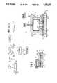
- the accumulator 30has two alternative forms as illustrated in FIGS. 2 and 3.
- FIGS. 2 and 3utilize the same numbering as in the '887 patent.
- the inletis represented by numeral 58 wherein fluid enters the accumulator from the inlet valve 26.
- the accumulatorcomprises a diaphragm 90, a backing plate 92, an end cap 94, and fill tube 96 and a spacer plate 98.
- the diaphragm 90deflects in response to fluid entry of the chamber 102.
- the backing plate 92acts as a mechanical stop to limit motion of the diaphragm.
- the spacer plate 98is used to limit diaphragm motion during discharge, that is, the passage of fluid through the outlet 59.
- spacer plate 98as a mechanical stop creates a problem when fragile materials such as insulin are used.
- the materialis locally compressed and crushed by the mechanical action of the diaphragm contacting the stop. This breaks down the fluid. Since the internal volumes are quite small, this in turn can result in residue formation inside the accumulator.
- the fill tube 96is used to supply an inert gas to the chamber 104.
- the purpose of chamber 104is to provide a region which is charged at a pressure lower than that of the infusate pressure in drug reservoir 18 so that accumulator chamber 102 fills when inlet valve 26 is opened, but higher in pressure than that of the catheter 36 to allow the diaphragm 90 to deflect back to the spacer plate 98 position as the chamber 102 empties when the outlet valve 28 is opened. Additional details of this accumulator may be found in U.S. Pat. No. 4,838,887.
- FIG. 3illustrates an alternative configuration.
- the backing plate 92comprises three elements which electrically isolate the center of the plate from the diaphragm 90.
- a supply of inert gasis still supplied via the feed fill tube 96.
- a lead 110is attached to a flange forming a portion of the end cap assembly.
- a ceramic cup 113which is lined with metal 111, provides a conductive path between a stop 114 and the lead 110.
- the diaphragm 90is used as a moving switch contact. This provides a signal indicating that the accumulator is full, that is, the diaphragm in an upward position contacting the stop 114. This electrical signal is used for diagnostic determinations of the system such as leaks in the valve.
- FIG. 3illustrates an alternative configuration.
- the backing plate 92comprises three elements which electrically isolate the center of the plate from the diaphragm 90.
- a supply of inert gasis still supplied via the feed fill tube 96.
- a lead 110is attached to
- valve accumulator systems discussed hereinfunction in a satisfactory manner and provide for an accurate metering of flow.
- one difficulty common to all valve systemsis damage to the fluid passing through it as a consequence of interaction with valves, diaphragms and the like.
- various types of insulinare particularly sensitive to mechanically induced damage which tends to break down that material. This in turn causes a build-up of precipitate at the very location in the system, the accumulator, where metering accuracy is desired. Over time clogging can occur.
- Yet another object of this inventionis to provide an accumulator configuration having minimal size to thereby reduce the overall packaging of implantable medical devices.
- a still further object of this inventionis to provide an accumulator which does not utilize mechanical stops or spacer plate contact in the infusate path, thereby minimizing fluid contact points.
- the first diaphragmperforms the steps of fluid transfer as in prior art systems.
- the second diaphragmis separated from the first by means of a transfer fluid.
- the first diaphragmhas no mechanical stops associated with it but deflects as a function of the difference in pressure between the drug chamber and the transfer fluid chamber.
- the second diaphragmdeflects between positions and has mechanical stops. It is biased by gas, springs and the like to provide a restoring bias hydraulically to the system, i.e., to cause the first diaphragm to store or expel fluid.
- a spring biased pressure platemay be used or, as an alternative to the transfer fluid, a chamfered slider element may be used.
- FIG. 1is a schematic diagram illustrating a complete implantable system which employs an accumulator as described in U.S. Pat. No. 4,838,887;
- FIG. 2is a schematic cut-away side view of an accumulator as described in U.S. Pat. No. 4,838,887;
- FIG. 3is a schematic cut-away side view of a modified accumulator illustrated in U.S. Pat. No. 4,838,887;
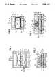
- FIG. 4is a schematic side view of an accumulator in accordance with the first preferred embodiment of this invention.
- FIG. 5is a schematic cut-away side view of an accumulator in accordance with a second preferred embodiment of this invention.
- FIG. 6is a schematic cut-away side view of an accumulator in accordance with a third preferred embodiment of this invention.
- FIG. 7is a schematic cut-away view of a fourth preferred embodiment of this invention.
- a drug chamber 41receives fluid via the inlet 42. It will be understood that the inlet 42 is coupled to an inlet valve, such as element 26 depicted in FIG. 1.
- the inlet pressureis approximately 8.5 psig.
- the inlet 42is formed in the spacer plate 43 which also has an outlet 44 from the drug chamber 41 of the accumulator.
- the accumulator of FIG. 4also includes an intermediate member 45 with flow passages 45a and surface grooves 45b, which defines a transfer fluid chamber 46.
- the presence of the surface grooves 45bis to allow the fluid to lift the diaphragm quicker thus decreasing the response time to fill from empty.
- the transfer fluid chamber 46is separated from the drug chamber 41 by means of a first diaphragm 47.
- the transfer fluid chamber 46is filled with transfer fluid 46a via a fill tube 48 which is sealed after the transfer fluid chamber 46 has been loaded.
- the transfer fluid 46amay be any incompressible, low vapor pressure fluid such as silicone oil, water, or other material which can be used hydraulically to transfer the pressure difference which exists across first diaphragm 47 through flow passages 45a to a second diaphragm 52.
- the second diaphragm 52has a constant back pressure bias based on the pressure in cavity 50.
- a backing plate 49defines the cavity 50 which is filled with an inert gas such as Argon loaded to 4 psig, utilizing the fill tube 51 as illustrated. This pressure can urge second diaphragm 52 downward, displacing the transfer fluid 46a in transfer fluid chamber 46 against first diaphragm 47, forcing a reduction in volume of drug chamber 41.
- the first diaphragm 47displaces as a function of the pressure difference between that which exists in the drug chamber 41 and in the transfer fluid chamber 46.
- the input pressure in chamber 41is greater than the pressure of transfer fluid 46a as biased by the gas in cavity 50. Therefore, the first diaphragm 47 deflects upward which in turn causes second diaphragm 52 to deflect upward.
- the volume in chamber 46remains constant since the transfer fluid 46ais incompressible.
- valve 28is opened chamber 41 empties as first diaphragm 47 and second diaphragm 52 deflect downward.
- first diaphragm 47is not controlled by any mechanical stops. Instead, its motion is limited by the volume of transfer fluid 46a displaced in cavity 46 which in turn is limited by the displacement of second diaphragm 52.
- the position of second diaphragm 52is maintained by backing plate 49 and intermediate member 45. These elements perform the same function as backing plate 92 and spacer plate 98 in FIG. 2, respectively.
- the second diaphragm 52is in direct fluid communication with the first diaphragm 47 via the transfer fluid 46a in second chamber 46 through flow passages 45a. Consequently, the volume displaced by second diaphragm 52 as it travels between backing plate 49 and intermediate member 45 is the identical volume displaced by first diaphragm 47 as it is urged up and down via the transfer fluid 46a in transfer fluid chamber 46.
- FIG. 5illustrates a second preferred embodiment of this invention.
- like componentsare designated with the same numerals as in FIG. 4. To the extent that those items function in a similar manner, they will not be discussed with respect to this second preferred embodiment.
- FIG. 5departs from FIG. 4 in several respects.
- a spacer disc 60 having perforationsis used in the transfer fluid chamber 46.
- the perforated dischas a series of holes to allow fluid communication between upper and lower surfaces thereof.
- the purpose of the disc 60is to provide mechanical limit stops to both the first and second diaphragms 47 and 52, respectively.
- FIG. 5does not utilize a gas back pressure chamber. Rather, a pressure plate 62 provides the necessary bias to second diaphragm 52. Pressure adjustment is accomplished by providing a section of the inner wall of member 49 with a threaded element. A compatible threaded back plate 66 is provided with a spring 68. By threading the plate 66 using threads 64, the spring tension is adjusted thereby providing variable pressure onto the pressure plate 62.
- This embodimenttherefore eliminates the second pressurized cavity 50. It is apparent however that the perforated disc 60 could be used in conjunction with the embodiment of FIG. 4 while still retaining the back pressure provided by the cavity 50.
- the disc 60has a surface texture characteristic such as micromachined flow channels or is roughened to provide a random flow pattern. Such is desired to decrease the response time of the system in a fashion similar to the use of surface grooves 45b of FIG. 4. That is, the valves need not be held in an open state longer than needed thus reducing battery power requirements.
- FIG. 6a third preferred embodiment of this invention is depicted.
- a chamfered slider 70is used in place of the perforated disc 60 of the second preferred embodiment.
- the slider 70employs contoured surfaces 72 and 74 on the upper and lower surfaces respectively.
- the slider 70is biased upward, that is, with the chamber 41 filled, it displaces second diaphragm 52 as illustrated.
- the chamber 41empties the slider 70 is lowered given the pressure differential across the second diaphragm 52.
- the second chamfered surface 74rests on the lower shoulder 77 of the spacer plate 43. This acts as a limit stop for the slider 70 and thus, first diaphragm 47 will no longer deflect.
- the stopis defined between the side of the first diaphragm 47 and lower shoulder 77 not in fluid contact with the infusate in chamber 41. Thus, that material cannot be damaged during passage through the accumulator.
- an upper shoulder 78 on backing plate 49acts as a limit stop for the slider 70 to control the upward motion of first diaphragm 47. It should be noted that upper shoulder 78 and/or lower shoulder 77 could also be located on intermediate member 45.
- FIG. 7A fourth preferred embodiment is illustrated in FIG. 7.
- the second diaphragmis in the form of an elastomeric diaphragm 80.
- the elastomeric diaphragm 80is clamped in place between the end cap 49 and a pressure spring adjustment member 82 which is threaded into place in a manner similar to that illustrated in FIG. 5.
- a push pin 84is spring biased by means of spring 86.
- the position of the pressure spring adjustment member 82sets the span between a head 85 of the push pin 84 and the upper flange 83 on adjustment member 82. This compresses the spring 86 which varies the back pressure on the pin and thus sets the position of the elastomeric diaphragm 80.
- the head 85 of the push pin 84is also limited in motion by the lower flange 87 on backing plate 49.
- FIG. 7illustrates the use of a perforated screen 88. This is an optional element for purposes of safety to limit the upward deflection of the first diaphragm 47. It is however not required.
- the spacer elementssuch as perforated disc 60
- a woven element or a porous plugcould be substituted for perforated disc 60.
- Absolute rigidityis required in any case so that the diaphragm is supported.
- the slider 70 of FIG. 6could be modified to include level sensing in the chamber 41 as a function of slider 70 position. This would be done by Hall effect, capacitive pick-up or metallic contact. By placing the sensor in the wall of intermediate member 45, the position of the slider 70 can be determined. The slider 70 would also be given a texture on surfaces contacting the first and second diaphragms 47 and 52, respectively, to increase flow-thru characteristics thus reducing power requirements.
Landscapes
- Health & Medical Sciences (AREA)
- Public Health (AREA)
- Engineering & Computer Science (AREA)
- Anesthesiology (AREA)
- Biomedical Technology (AREA)
- Heart & Thoracic Surgery (AREA)
- Hematology (AREA)
- Life Sciences & Earth Sciences (AREA)
- Animal Behavior & Ethology (AREA)
- Vascular Medicine (AREA)
- General Health & Medical Sciences (AREA)
- Veterinary Medicine (AREA)
- Physics & Mathematics (AREA)
- Fluid Mechanics (AREA)
- Reciprocating Pumps (AREA)
- Infusion, Injection, And Reservoir Apparatuses (AREA)
- Pharmaceuticals Containing Other Organic And Inorganic Compounds (AREA)
- Prostheses (AREA)
- External Artificial Organs (AREA)
- Supply Devices, Intensifiers, Converters, And Telemotors (AREA)
- Details Of Reciprocating Pumps (AREA)
Abstract
Description
Claims (25)
Priority Applications (10)
| Application Number | Priority Date | Filing Date | Title |
|---|---|---|---|
| US07/946,848US5281210A (en) | 1992-09-18 | 1992-09-18 | Accumulator for implantable pump |
| AU46840/93AAU674332B2 (en) | 1992-09-18 | 1993-07-22 | Accumulator for implantable pump |
| DE9390324UDE9390324U1 (en) | 1992-09-18 | 1993-07-22 | Pressure accumulator for implantable pumps |
| EP93917277AEP0660728B1 (en) | 1992-09-18 | 1993-07-22 | Accumulator for implantable pump |
| ES93917277TES2099461T3 (en) | 1992-09-18 | 1993-07-22 | ACCUMULATOR FOR IMPLANTABLE PUMP. |
| CA002142980ACA2142980C (en) | 1992-09-18 | 1993-07-22 | Accumulator for implantable pump |
| JP6508065AJP2744136B2 (en) | 1992-09-18 | 1993-07-22 | Bio-implantable pump accumulator |
| DE69308578TDE69308578T2 (en) | 1992-09-18 | 1993-07-22 | MEMORY FOR IMPLANTABLE PUMP |
| PCT/US1993/006775WO1994006492A1 (en) | 1992-09-18 | 1993-07-22 | Accumulator for implantable pump |
| AT93917277TATE149356T1 (en) | 1992-09-18 | 1993-07-22 | STORAGE FOR IMPLANTABLE PUMP |
Applications Claiming Priority (1)
| Application Number | Priority Date | Filing Date | Title |
|---|---|---|---|
| US07/946,848US5281210A (en) | 1992-09-18 | 1992-09-18 | Accumulator for implantable pump |
Publications (1)
| Publication Number | Publication Date |
|---|---|
| US5281210Atrue US5281210A (en) | 1994-01-25 |
Family
ID=25485062
Family Applications (1)
| Application Number | Title | Priority Date | Filing Date |
|---|---|---|---|
| US07/946,848Expired - LifetimeUS5281210A (en) | 1992-09-18 | 1992-09-18 | Accumulator for implantable pump |
Country Status (9)
| Country | Link |
|---|---|
| US (1) | US5281210A (en) |
| EP (1) | EP0660728B1 (en) |
| JP (1) | JP2744136B2 (en) |
| AT (1) | ATE149356T1 (en) |
| AU (1) | AU674332B2 (en) |
| CA (1) | CA2142980C (en) |
| DE (2) | DE69308578T2 (en) |
| ES (1) | ES2099461T3 (en) |
| WO (1) | WO1994006492A1 (en) |
Cited By (37)
| Publication number | Priority date | Publication date | Assignee | Title |
|---|---|---|---|---|
| US5616132A (en)* | 1995-06-09 | 1997-04-01 | Subot, Inc. | Injection device |
| WO1999038553A1 (en)* | 1998-02-02 | 1999-08-05 | Medtronic, Inc. | Implantable drug infusion device having an improved valve |
| WO1999062586A1 (en)* | 1998-05-29 | 1999-12-09 | Wayne State University | Programmable antisiphon shunt system |
| WO1999065540A3 (en)* | 1998-06-18 | 2000-08-24 | Medical Research Group Inc | Medical infusion device with a source of controlled compliance |
| US6203523B1 (en)* | 1998-02-02 | 2001-03-20 | Medtronic Inc | Implantable drug infusion device having a flow regulator |
| US6270326B1 (en) | 1997-08-29 | 2001-08-07 | Seiko Epson Corporation | Transfusion device and liquid supply tube |
| US6471689B1 (en)* | 1999-08-16 | 2002-10-29 | Thomas Jefferson University | Implantable drug delivery catheter system with capillary interface |
| US6471675B1 (en)* | 1999-04-30 | 2002-10-29 | Medtronic, Inc. | Passive flow control devices for implantable pumps |
| US6635049B1 (en)* | 1999-04-30 | 2003-10-21 | Medtronic, Inc. | Drug bolus delivery system |
| EP1356837A1 (en)* | 1998-06-18 | 2003-10-29 | Medical Research Group, Inc. | Medical infusion device with a source of controlled compliance |
| US20030208184A1 (en)* | 2000-01-11 | 2003-11-06 | Paul Burke | Implantable, refillable infusion device and spetum replacement kit |
| US20040073175A1 (en)* | 2002-01-07 | 2004-04-15 | Jacobson James D. | Infusion system |
| US20060089620A1 (en)* | 2003-06-25 | 2006-04-27 | Gibson Scott R | Medication infusion device using negatively biased ambient pressure medication chamber |
| US20060116648A1 (en)* | 2004-07-26 | 2006-06-01 | Bret Hamatake | Port design and method of assembly |
| US20080234637A1 (en)* | 2007-03-24 | 2008-09-25 | Mcconnell Susan | Valves, Valved Fluid Transfer Devices and Ambulatory Infusion Devices Including The Same |
| US20080234638A1 (en)* | 2007-03-24 | 2008-09-25 | David Christopher Antonio | Valves, Valved Fluid Transfer Devices and Ambulatory Infusion Devices Including The Same |
| US20090012503A1 (en)* | 2004-11-10 | 2009-01-08 | Hironao Kawano | Body-Insertable Apparatus |
| US20090157005A1 (en)* | 2003-04-23 | 2009-06-18 | Gonnelli Robert R | Hydraulically actuated pump for long duration medicament administration |
| US20090227989A1 (en)* | 2008-03-05 | 2009-09-10 | Burke Paul F | Multiple reservoir implantable drug infusion device and method |
| RU2372871C1 (en)* | 2008-02-13 | 2009-11-20 | Общество с ограниченной ответственностью "Эфа" (ООО "Эфа") | Gas feed unit for argon-plasma coagulation |
| US20100042215A1 (en)* | 2008-08-13 | 2010-02-18 | Stalcup Gregory C | Orthopaedic implant |
| US20100042226A1 (en)* | 2008-08-13 | 2010-02-18 | Nebosky Paul S | Orthopaedic implant with spatially varying porosity |
| US20100042167A1 (en)* | 2008-08-13 | 2010-02-18 | Nebosky Paul S | Orthopaedic screws |
| US20100042213A1 (en)* | 2008-08-13 | 2010-02-18 | Nebosky Paul S | Drug delivery implants |
| US20100042214A1 (en)* | 2008-08-13 | 2010-02-18 | Nebosky Paul S | Drug delivery implants |
| US7914499B2 (en) | 2006-03-30 | 2011-03-29 | Valeritas, Inc. | Multi-cartridge fluid delivery device |
| US20110166522A1 (en)* | 2010-01-06 | 2011-07-07 | Medtronic, Inc. | Accumulator for therapeutic fluid delivery devices |
| US8273058B2 (en) | 2007-10-04 | 2012-09-25 | Flowonix Medical Incorporated | Two way accumulator programmable valve pump |
| US8545484B2 (en) | 2011-10-18 | 2013-10-01 | Medtronic, Inc. | Accumulator for implantable infusion device |
| US8740861B2 (en) | 2007-03-24 | 2014-06-03 | Medallion Therapeutics, Inc. | Valves, valved fluid transfer devices and ambulatory infusion devices including the same |
| US9089636B2 (en) | 2004-07-02 | 2015-07-28 | Valeritas, Inc. | Methods and devices for delivering GLP-1 and uses thereof |
| US9700431B2 (en) | 2008-08-13 | 2017-07-11 | Smed-Ta/Td, Llc | Orthopaedic implant with porous structural member |
| US10842645B2 (en) | 2008-08-13 | 2020-11-24 | Smed-Ta/Td, Llc | Orthopaedic implant with porous structural member |
| US11745003B2 (en) | 2020-10-30 | 2023-09-05 | Medtronic, Inc. | Implantable access port with one-directional filter |
| US11931545B2 (en) | 2020-10-30 | 2024-03-19 | Medtronic, Inc. | Drug infusion port |
| US11992642B2 (en) | 2020-10-30 | 2024-05-28 | Medtronic, Inc. | Implantable medical device for delivery of pharmacological agents to the deep brain structures |
| US12226609B2 (en) | 2020-12-16 | 2025-02-18 | Medtronic, Inc. | Method to detect inadvertent delivery of drug to a subcutaneous pocket |
Families Citing this family (1)
| Publication number | Priority date | Publication date | Assignee | Title |
|---|---|---|---|---|
| KR102250698B1 (en)* | 2019-05-13 | 2021-05-12 | 주식회사 필로시스 | Method and device to inject medicine |
Citations (10)
| Publication number | Priority date | Publication date | Assignee | Title |
|---|---|---|---|---|
| US4299220A (en)* | 1979-05-03 | 1981-11-10 | The Regents Of The University Of Minnesota | Implantable drug infusion regulator |
| US4668231A (en)* | 1984-02-15 | 1987-05-26 | Cordis Corporation | Implantable hand-operable dispensers for fluid medicaments |
| US4699615A (en)* | 1984-06-21 | 1987-10-13 | Fischell David R | Finger actuated medication infusion system |
| US4820273A (en)* | 1988-03-01 | 1989-04-11 | Eaton Corporation | Implantable medication infusion device and bolus generator therefor |
| US4838887A (en)* | 1987-12-15 | 1989-06-13 | Shiley Infusaid Inc. | Programmable valve pump |
| US4969873A (en)* | 1988-06-23 | 1990-11-13 | Annemarie Schlogl Gesellschaft m.b.H. & Co., KG | Device for dispensing active substances to a patient |
| US5049141A (en)* | 1990-04-25 | 1991-09-17 | Infusaid, Inc. | Programmable valve pump |
| US5053031A (en)* | 1988-03-29 | 1991-10-01 | Baxter International Inc. | Pump infusion system |
| US5090963A (en)* | 1990-10-19 | 1992-02-25 | Product Development (Z.G.S.) Ltd. | Electrochemically driven metering medicament dispenser |
| US5137529A (en)* | 1990-02-20 | 1992-08-11 | Pudenz-Schulte Medical Research Corporation | Injection port |
Family Cites Families (6)
| Publication number | Priority date | Publication date | Assignee | Title |
|---|---|---|---|---|
| DE2626348C3 (en)* | 1976-06-11 | 1980-01-31 | Siemens Ag, 1000 Berlin Und 8000 Muenchen | Implantable dosing device |
| JPS5816901B2 (en)* | 1976-11-09 | 1983-04-02 | 日機装株式会社 | pulsatile blood pump |
| US4443218A (en)* | 1982-09-09 | 1984-04-17 | Infusaid Corporation | Programmable implantable infusate pump |
| US4714462A (en)* | 1986-02-03 | 1987-12-22 | Intermedics Infusaid, Inc. | Positive pressure programmable infusion pump |
| DE3634725A1 (en)* | 1986-10-11 | 1988-04-14 | Holzer Walter | Dosing pump, e.g. for insulin |
| IT1231308B (en)* | 1989-07-27 | 1991-11-28 | Tetra Dev Co | PISTON UNIT WITH ROLLING MEMBRANE |
- 1992
- 1992-09-18USUS07/946,848patent/US5281210A/ennot_activeExpired - Lifetime
- 1993
- 1993-07-22DEDE69308578Tpatent/DE69308578T2/ennot_activeExpired - Lifetime
- 1993-07-22CACA002142980Apatent/CA2142980C/ennot_activeExpired - Fee Related
- 1993-07-22DEDE9390324Upatent/DE9390324U1/ennot_activeExpired - Lifetime
- 1993-07-22EPEP93917277Apatent/EP0660728B1/ennot_activeExpired - Lifetime
- 1993-07-22ATAT93917277Tpatent/ATE149356T1/ennot_activeIP Right Cessation
- 1993-07-22JPJP6508065Apatent/JP2744136B2/ennot_activeExpired - Fee Related
- 1993-07-22AUAU46840/93Apatent/AU674332B2/ennot_activeCeased
- 1993-07-22ESES93917277Tpatent/ES2099461T3/ennot_activeExpired - Lifetime
- 1993-07-22WOPCT/US1993/006775patent/WO1994006492A1/enactiveIP Right Grant
Patent Citations (10)
| Publication number | Priority date | Publication date | Assignee | Title |
|---|---|---|---|---|
| US4299220A (en)* | 1979-05-03 | 1981-11-10 | The Regents Of The University Of Minnesota | Implantable drug infusion regulator |
| US4668231A (en)* | 1984-02-15 | 1987-05-26 | Cordis Corporation | Implantable hand-operable dispensers for fluid medicaments |
| US4699615A (en)* | 1984-06-21 | 1987-10-13 | Fischell David R | Finger actuated medication infusion system |
| US4838887A (en)* | 1987-12-15 | 1989-06-13 | Shiley Infusaid Inc. | Programmable valve pump |
| US4820273A (en)* | 1988-03-01 | 1989-04-11 | Eaton Corporation | Implantable medication infusion device and bolus generator therefor |
| US5053031A (en)* | 1988-03-29 | 1991-10-01 | Baxter International Inc. | Pump infusion system |
| US4969873A (en)* | 1988-06-23 | 1990-11-13 | Annemarie Schlogl Gesellschaft m.b.H. & Co., KG | Device for dispensing active substances to a patient |
| US5137529A (en)* | 1990-02-20 | 1992-08-11 | Pudenz-Schulte Medical Research Corporation | Injection port |
| US5049141A (en)* | 1990-04-25 | 1991-09-17 | Infusaid, Inc. | Programmable valve pump |
| US5090963A (en)* | 1990-10-19 | 1992-02-25 | Product Development (Z.G.S.) Ltd. | Electrochemically driven metering medicament dispenser |
Cited By (81)
| Publication number | Priority date | Publication date | Assignee | Title |
|---|---|---|---|---|
| US5616132A (en)* | 1995-06-09 | 1997-04-01 | Subot, Inc. | Injection device |
| US6270326B1 (en) | 1997-08-29 | 2001-08-07 | Seiko Epson Corporation | Transfusion device and liquid supply tube |
| US6203523B1 (en)* | 1998-02-02 | 2001-03-20 | Medtronic Inc | Implantable drug infusion device having a flow regulator |
| WO1999038553A1 (en)* | 1998-02-02 | 1999-08-05 | Medtronic, Inc. | Implantable drug infusion device having an improved valve |
| US6878135B1 (en) | 1998-02-02 | 2005-04-12 | Medtronic, Inc. | Implantable drug infusion device having a flow regulator |
| US6090062A (en)* | 1998-05-29 | 2000-07-18 | Wayne State University | Programmable antisiphon shunt system |
| WO1999062586A1 (en)* | 1998-05-29 | 1999-12-09 | Wayne State University | Programmable antisiphon shunt system |
| WO1999065540A3 (en)* | 1998-06-18 | 2000-08-24 | Medical Research Group Inc | Medical infusion device with a source of controlled compliance |
| US6537268B1 (en) | 1998-06-18 | 2003-03-25 | Medtronic Minimed, Inc. | Medical infusion device with a source of controlled compliance |
| EP1356837A1 (en)* | 1998-06-18 | 2003-10-29 | Medical Research Group, Inc. | Medical infusion device with a source of controlled compliance |
| US6471675B1 (en)* | 1999-04-30 | 2002-10-29 | Medtronic, Inc. | Passive flow control devices for implantable pumps |
| US6635049B1 (en)* | 1999-04-30 | 2003-10-21 | Medtronic, Inc. | Drug bolus delivery system |
| US6979315B2 (en) | 1999-04-30 | 2005-12-27 | Medtronic, Inc. | Passive flow control devices for implantable pumps |
| US6471689B1 (en)* | 1999-08-16 | 2002-10-29 | Thomas Jefferson University | Implantable drug delivery catheter system with capillary interface |
| US7108686B2 (en) | 2000-01-11 | 2006-09-19 | Bard Access Systems, Inc. | Implantable, refillable infusion device and septum replacement kit |
| US20030208184A1 (en)* | 2000-01-11 | 2003-11-06 | Paul Burke | Implantable, refillable infusion device and spetum replacement kit |
| US6764472B1 (en) | 2000-01-11 | 2004-07-20 | Bard Access Systems, Inc. | Implantable refillable infusion device |
| US20040249363A1 (en)* | 2000-01-11 | 2004-12-09 | Bard Access Systems, Inc. | Implantable, refillable infusion device and septum replacement kit |
| US20040073175A1 (en)* | 2002-01-07 | 2004-04-15 | Jacobson James D. | Infusion system |
| US9072828B2 (en) | 2003-04-23 | 2015-07-07 | Valeritas, Inc. | Hydraulically actuated pump for long duration medicament administration |
| US11642456B2 (en) | 2003-04-23 | 2023-05-09 | Mannkind Corporation | Hydraulically actuated pump for fluid administration |
| US10525194B2 (en) | 2003-04-23 | 2020-01-07 | Valeritas, Inc. | Hydraulically actuated pump for fluid administration |
| US20090157005A1 (en)* | 2003-04-23 | 2009-06-18 | Gonnelli Robert R | Hydraulically actuated pump for long duration medicament administration |
| US20090198185A1 (en)* | 2003-04-23 | 2009-08-06 | Gonnelli Robert R | Hydraulically actuated pump for long duration medicament administration |
| US8070726B2 (en) | 2003-04-23 | 2011-12-06 | Valeritas, Inc. | Hydraulically actuated pump for long duration medicament administration |
| US9511187B2 (en) | 2003-04-23 | 2016-12-06 | Valeritas, Inc. | Hydraulically actuated pump for fluid administration |
| US9125983B2 (en) | 2003-04-23 | 2015-09-08 | Valeritas, Inc. | Hydraulically actuated pump for fluid administration |
| US8070745B2 (en) | 2003-06-25 | 2011-12-06 | The Alfred E. Mann Foundation For Scientific Research | Medication infusion device using negatively biased ambient pressure medication chamber |
| US20060089620A1 (en)* | 2003-06-25 | 2006-04-27 | Gibson Scott R | Medication infusion device using negatively biased ambient pressure medication chamber |
| US8932253B2 (en) | 2003-06-25 | 2015-01-13 | Medallion Therapeutics, Inc. | Medication infusion device using negatively biased ambient pressure medication chamber |
| US9089636B2 (en) | 2004-07-02 | 2015-07-28 | Valeritas, Inc. | Methods and devices for delivering GLP-1 and uses thereof |
| US20060116648A1 (en)* | 2004-07-26 | 2006-06-01 | Bret Hamatake | Port design and method of assembly |
| US8100889B2 (en)* | 2004-11-10 | 2012-01-24 | Olympus Corporation | Body-insertable apparatus |
| US20090012503A1 (en)* | 2004-11-10 | 2009-01-08 | Hironao Kawano | Body-Insertable Apparatus |
| US12246159B2 (en) | 2006-03-30 | 2025-03-11 | Mannkind Corporation | Multi-cartridge fluid delivery device |
| US7914499B2 (en) | 2006-03-30 | 2011-03-29 | Valeritas, Inc. | Multi-cartridge fluid delivery device |
| US8361053B2 (en) | 2006-03-30 | 2013-01-29 | Valeritas, Inc. | Multi-cartridge fluid delivery device |
| US8821443B2 (en) | 2006-03-30 | 2014-09-02 | Valeritas, Inc. | Multi-cartridge fluid delivery device |
| US9687599B2 (en) | 2006-03-30 | 2017-06-27 | Valeritas, Inc. | Multi-cartridge fluid delivery device |
| US10493199B2 (en) | 2006-03-30 | 2019-12-03 | Valeritas, Inc. | Multi-cartridge fluid delivery device |
| US8251960B2 (en) | 2007-03-24 | 2012-08-28 | The Alfred E. Mann Foundation For Scientific Research | Valves, valved fluid transfer devices and ambulatory infusion devices including the same |
| US8551055B2 (en) | 2007-03-24 | 2013-10-08 | The Alfred E. Mann Foundation For Scientific Research | Valves, valved fluid transfer devices and ambulatory infusion devices including the same |
| US20080234637A1 (en)* | 2007-03-24 | 2008-09-25 | Mcconnell Susan | Valves, Valved Fluid Transfer Devices and Ambulatory Infusion Devices Including The Same |
| US20080234638A1 (en)* | 2007-03-24 | 2008-09-25 | David Christopher Antonio | Valves, Valved Fluid Transfer Devices and Ambulatory Infusion Devices Including The Same |
| US20080234639A1 (en)* | 2007-03-24 | 2008-09-25 | David Christopher Antonio | Valves, Valved Fluid Transfer Devices and Ambulatory Infusion Devices Including The Same |
| US10004848B2 (en) | 2007-03-24 | 2018-06-26 | Medallion Therapeutics, Inc. | Valves, valved fluid transfer devices and ambulatory infusion devices including the same |
| US9968741B2 (en) | 2007-03-24 | 2018-05-15 | Medallion Therapeutics, Inc. | Valves, valved fluid transfer devices and ambulatory infusion devices including the same |
| US9463311B2 (en) | 2007-03-24 | 2016-10-11 | Medallion Therapeutics, Inc. | Valves, valved fluid transfer devices and ambulatory infusion devices including the same |
| US8936579B2 (en) | 2007-03-24 | 2015-01-20 | Medallion Therapeutics, Inc. | Valves, valved fluid transfer devices and ambulatory infusion devices including the same |
| US8936580B2 (en) | 2007-03-24 | 2015-01-20 | Medallion Therapeutics, Inc. | Valves, valved fluid transfer devices and ambulatory infusion devices including the same |
| US8740861B2 (en) | 2007-03-24 | 2014-06-03 | Medallion Therapeutics, Inc. | Valves, valved fluid transfer devices and ambulatory infusion devices including the same |
| US9468717B2 (en) | 2007-03-24 | 2016-10-18 | Medallion Therapeutics, Inc. | Valves, valved fluid transfer devices and ambulatory infusion devices including the same |
| US8273058B2 (en) | 2007-10-04 | 2012-09-25 | Flowonix Medical Incorporated | Two way accumulator programmable valve pump |
| US8696627B2 (en) | 2007-10-04 | 2014-04-15 | Paul Burke | Two way accumulator programmable valve pump |
| RU2372871C1 (en)* | 2008-02-13 | 2009-11-20 | Общество с ограниченной ответственностью "Эфа" (ООО "Эфа") | Gas feed unit for argon-plasma coagulation |
| US20100089487A1 (en)* | 2008-03-05 | 2010-04-15 | Burke Paul F | Multiple reservoir implantable drug infusion device and method |
| US8551044B2 (en) | 2008-03-05 | 2013-10-08 | Flowonix Medical Incorporated | Multiple reservoir implantable drug infusion device and method |
| US20090227989A1 (en)* | 2008-03-05 | 2009-09-10 | Burke Paul F | Multiple reservoir implantable drug infusion device and method |
| US8545477B2 (en) | 2008-03-05 | 2013-10-01 | Flowonix Medical Incorporated | Multiple reservoir implantable drug infusion device and method |
| US10349993B2 (en) | 2008-08-13 | 2019-07-16 | Smed-Ta/Td, Llc | Drug delivery implants |
| US20100042226A1 (en)* | 2008-08-13 | 2010-02-18 | Nebosky Paul S | Orthopaedic implant with spatially varying porosity |
| US20100042215A1 (en)* | 2008-08-13 | 2010-02-18 | Stalcup Gregory C | Orthopaedic implant |
| US9561354B2 (en) | 2008-08-13 | 2017-02-07 | Smed-Ta/Td, Llc | Drug delivery implants |
| US9616205B2 (en) | 2008-08-13 | 2017-04-11 | Smed-Ta/Td, Llc | Drug delivery implants |
| US8702767B2 (en) | 2008-08-13 | 2014-04-22 | Smed-Ta/Td, Llc | Orthopaedic Screws |
| US9700431B2 (en) | 2008-08-13 | 2017-07-11 | Smed-Ta/Td, Llc | Orthopaedic implant with porous structural member |
| US20100042213A1 (en)* | 2008-08-13 | 2010-02-18 | Nebosky Paul S | Drug delivery implants |
| US9358056B2 (en) | 2008-08-13 | 2016-06-07 | Smed-Ta/Td, Llc | Orthopaedic implant |
| US20100042167A1 (en)* | 2008-08-13 | 2010-02-18 | Nebosky Paul S | Orthopaedic screws |
| US10357298B2 (en) | 2008-08-13 | 2019-07-23 | Smed-Ta/Td, Llc | Drug delivery implants |
| US20100042214A1 (en)* | 2008-08-13 | 2010-02-18 | Nebosky Paul S | Drug delivery implants |
| US8475505B2 (en) | 2008-08-13 | 2013-07-02 | Smed-Ta/Td, Llc | Orthopaedic screws |
| US10842645B2 (en) | 2008-08-13 | 2020-11-24 | Smed-Ta/Td, Llc | Orthopaedic implant with porous structural member |
| US11426291B2 (en) | 2008-08-13 | 2022-08-30 | Smed-Ta/Td, Llc | Orthopaedic implant with porous structural member |
| US20110166522A1 (en)* | 2010-01-06 | 2011-07-07 | Medtronic, Inc. | Accumulator for therapeutic fluid delivery devices |
| US8545484B2 (en) | 2011-10-18 | 2013-10-01 | Medtronic, Inc. | Accumulator for implantable infusion device |
| US11745003B2 (en) | 2020-10-30 | 2023-09-05 | Medtronic, Inc. | Implantable access port with one-directional filter |
| US11931545B2 (en) | 2020-10-30 | 2024-03-19 | Medtronic, Inc. | Drug infusion port |
| US11992642B2 (en) | 2020-10-30 | 2024-05-28 | Medtronic, Inc. | Implantable medical device for delivery of pharmacological agents to the deep brain structures |
| US12220553B2 (en) | 2020-10-30 | 2025-02-11 | Medtronic, Inc. | Implantable access port with one-directional filter |
| US12226609B2 (en) | 2020-12-16 | 2025-02-18 | Medtronic, Inc. | Method to detect inadvertent delivery of drug to a subcutaneous pocket |
Also Published As
| Publication number | Publication date |
|---|---|
| AU4684093A (en) | 1994-04-12 |
| DE9390324U1 (en) | 1995-09-14 |
| WO1994006492A1 (en) | 1994-03-31 |
| EP0660728A1 (en) | 1995-07-05 |
| ATE149356T1 (en) | 1997-03-15 |
| DE69308578D1 (en) | 1997-04-10 |
| JPH07509168A (en) | 1995-10-12 |
| DE69308578T2 (en) | 1997-06-12 |
| JP2744136B2 (en) | 1998-04-28 |
| EP0660728B1 (en) | 1997-03-05 |
| CA2142980C (en) | 1999-10-05 |
| ES2099461T3 (en) | 1997-05-16 |
| AU674332B2 (en) | 1996-12-19 |
| CA2142980A1 (en) | 1994-03-31 |
Similar Documents
| Publication | Publication Date | Title |
|---|---|---|
| US5281210A (en) | Accumulator for implantable pump | |
| KR0139651B1 (en) | Programmable valve pump | |
| EP0387439B1 (en) | Implantable infusion device | |
| US4221219A (en) | Implantable infusion apparatus and method | |
| US4944659A (en) | Implantable piezoelectric pump system | |
| EP0488701B1 (en) | Liquid-vapour pressure reservoir for medication infusion pump | |
| US4715852A (en) | Implanted medication infusion device | |
| US4714462A (en) | Positive pressure programmable infusion pump | |
| US4447224A (en) | Variable flow implantable infusion apparatus | |
| US5607418A (en) | Implantable drug delivery apparatus | |
| US8696627B2 (en) | Two way accumulator programmable valve pump | |
| JPH10500342A (en) | Liquid supply device | |
| CA1307178C (en) | Programmable valve pump | |
| WO2021119101A1 (en) | Flowrate control for self-pressurized reservoir of a device for delivering medication |
Legal Events
| Date | Code | Title | Description |
|---|---|---|---|
| AS | Assignment | Owner name:INFUSAID, INC., MASSACHUSETTS Free format text:ASSIGNMENT OF ASSIGNORS INTEREST.;ASSIGNORS:BURKE, PAUL F.;IDRISS, SAMIR;REEL/FRAME:006303/0606 Effective date:19920908 | |
| STCF | Information on status: patent grant | Free format text:PATENTED CASE | |
| FPAY | Fee payment | Year of fee payment:4 | |
| AS | Assignment | Owner name:PROGRAMMABLE PUMP TECHNOLOGIES, INC., NEW YORK Free format text:ASSIGNMENT OF ASSIGNORS INTEREST;ASSIGNOR:STRATO/INFUSAID, INC.;REEL/FRAME:008579/0381 Effective date:19970618 | |
| FEPP | Fee payment procedure | Free format text:PAT HOLDER CLAIMS SMALL ENTITY STATUS - SMALL BUSINESS (ORIGINAL EVENT CODE: SM02); ENTITY STATUS OF PATENT OWNER: SMALL ENTITY | |
| FPAY | Fee payment | Year of fee payment:8 | |
| FPAY | Fee payment | Year of fee payment:12 | |
| AS | Assignment | Owner name:INFUMEDICS, INC., MASSACHUSETTS Free format text:ASSIGNMENT OF ASSIGNORS INTEREST;ASSIGNOR:PROGRAMMABLE PUMP TECHNOLOGIES, INC.;REEL/FRAME:017400/0899 Effective date:20050816 | |
| AS | Assignment | Owner name:INSET TECHNOLOGIES INCORPORATED, NEW JERSEY Free format text:ASSIGNMENT OF ASSIGNORS INTEREST;ASSIGNOR:INFUMEDICS, INC.;REEL/FRAME:021701/0484 Effective date:20081009 | |
| FEPP | Fee payment procedure | Free format text:PAYOR NUMBER ASSIGNED (ORIGINAL EVENT CODE: ASPN); ENTITY STATUS OF PATENT OWNER: SMALL ENTITY | |
| AS | Assignment | Owner name:STRATO/INFUSAID, INC.,MASSACHUSETTS Free format text:MERGER;ASSIGNOR:INFUSAID, INC.;REEL/FRAME:024334/0400 Effective date:19950125 | |
| AS | Assignment | Owner name:MEDASYS INCORPORATED,NEW JERSEY Free format text:CHANGE OF NAME;ASSIGNOR:INSET TECHNOLOGIES INCORPORATED;REEL/FRAME:024547/0023 Effective date:20100323 | |
| AS | Assignment | Owner name:FLOWONIX MEDICAL INCORPORATED, NEW JERSEY Free format text:CHANGE OF NAME;ASSIGNOR:MEDASYS INCORPORATED;REEL/FRAME:028023/0921 Effective date:20120224 | |
| AS | Assignment | Owner name:SILICON VALLEY BANK, CALIFORNIA Free format text:INTELLECTUAL PROPERTY SECURITY AGREEMENT;ASSIGNOR:FLOWONIX MEDICAL INCORPORATED;REEL/FRAME:055297/0961 Effective date:20210212 | |
| AS | Assignment | Owner name:FLOWONIX MEDICAL INCORPORATED, NEW JERSEY Free format text:RELEASE BY SECURED PARTY;ASSIGNOR:SILICON VALLEY BANK;REEL/FRAME:062733/0192 Effective date:20230215 |