US5281206A - Needle connector with rotatable collar - Google Patents
Needle connector with rotatable collarDownload PDFInfo
- Publication number
- US5281206A US5281206AUS07/747,010US74701091AUS5281206AUS 5281206 AUS5281206 AUS 5281206AUS 74701091 AUS74701091 AUS 74701091AUS 5281206 AUS5281206 AUS 5281206A
- Authority
- US
- United States
- Prior art keywords
- needle
- collar
- tubular body
- connector
- cap member
- Prior art date
- Legal status (The legal status is an assumption and is not a legal conclusion. Google has not performed a legal analysis and makes no representation as to the accuracy of the status listed.)
- Expired - Lifetime
Links
- 239000012530fluidSubstances0.000claimsabstractdescription27
- 238000004891communicationMethods0.000claimsdescription4
- 239000003814drugSubstances0.000description30
- 229940079593drugDrugs0.000description30
- 230000007246mechanismEffects0.000description30
- 238000001990intravenous administrationMethods0.000description18
- 239000007788liquidSubstances0.000description17
- 241000894006BacteriaSpecies0.000description9
- 208000012266Needlestick injuryDiseases0.000description8
- 239000000463materialSubstances0.000description8
- 239000008280bloodSubstances0.000description7
- 210000004369bloodAnatomy0.000description7
- 238000011109contaminationMethods0.000description6
- 238000013461designMethods0.000description6
- 210000003811fingerAnatomy0.000description6
- 229920003023plasticPolymers0.000description6
- 239000000853adhesiveSubstances0.000description5
- 230000001070adhesive effectEffects0.000description5
- 230000000994depressogenic effectEffects0.000description5
- 238000004519manufacturing processMethods0.000description5
- 238000000034methodMethods0.000description4
- 239000004033plasticSubstances0.000description4
- 238000007789sealingMethods0.000description4
- 210000003462veinAnatomy0.000description4
- 230000000295complement effectEffects0.000description3
- 208000015181infectious diseaseDiseases0.000description3
- 230000013011matingEffects0.000description3
- 239000002245particleSubstances0.000description3
- 206010069803Injury associated with deviceDiseases0.000description2
- 239000004677NylonSubstances0.000description2
- 230000009471actionEffects0.000description2
- 230000001580bacterial effectEffects0.000description2
- 239000003795chemical substances by applicationSubstances0.000description2
- 210000000038chestAnatomy0.000description2
- 238000010276constructionMethods0.000description2
- 229920000126latexPolymers0.000description2
- 210000004932little fingerAnatomy0.000description2
- 238000012986modificationMethods0.000description2
- 230000004048modificationEffects0.000description2
- 229920001778nylonPolymers0.000description2
- 230000000149penetrating effectEffects0.000description2
- 239000004926polymethyl methacrylateSubstances0.000description2
- 238000007790scrapingMethods0.000description2
- 238000012360testing methodMethods0.000description2
- 235000010005Catalpa ovataNutrition0.000description1
- 240000004528Catalpa ovataSpecies0.000description1
- LFQSCWFLJHTTHZ-UHFFFAOYSA-NEthanolChemical compoundCCOLFQSCWFLJHTTHZ-UHFFFAOYSA-N0.000description1
- 230000015572biosynthetic processEffects0.000description1
- 230000036772blood pressureEffects0.000description1
- 238000009534blood testMethods0.000description1
- 235000013351cheeseNutrition0.000description1
- 239000011248coating agentSubstances0.000description1
- 238000000576coating methodMethods0.000description1
- 230000003111delayed effectEffects0.000description1
- 230000000881depressing effectEffects0.000description1
- 238000001647drug administrationMethods0.000description1
- 230000002708enhancing effectEffects0.000description1
- 238000011010flushing procedureMethods0.000description1
- -1for exampleSubstances0.000description1
- 231100000206health hazardToxicity0.000description1
- 238000003780insertionMethods0.000description1
- 230000037431insertionEffects0.000description1
- 239000004816latexSubstances0.000description1
- 231100000518lethalToxicity0.000description1
- 230000001665lethal effectEffects0.000description1
- 210000002445nippleAnatomy0.000description1
- 238000004806packaging method and processMethods0.000description1
- 230000000737periodic effectEffects0.000description1
- 239000004417polycarbonateSubstances0.000description1
- 229920000515polycarbonatePolymers0.000description1
- 230000001681protective effectEffects0.000description1
- 230000003014reinforcing effectEffects0.000description1
- 238000009877renderingMethods0.000description1
- 230000008439repair processEffects0.000description1
Images


Classifications
- A—HUMAN NECESSITIES
- A61—MEDICAL OR VETERINARY SCIENCE; HYGIENE
- A61M—DEVICES FOR INTRODUCING MEDIA INTO, OR ONTO, THE BODY; DEVICES FOR TRANSDUCING BODY MEDIA OR FOR TAKING MEDIA FROM THE BODY; DEVICES FOR PRODUCING OR ENDING SLEEP OR STUPOR
- A61M39/00—Tubes, tube connectors, tube couplings, valves, access sites or the like, specially adapted for medical use
- A61M39/10—Tube connectors; Tube couplings
- A61M39/1011—Locking means for securing connection; Additional tamper safeties
- A—HUMAN NECESSITIES
- A61—MEDICAL OR VETERINARY SCIENCE; HYGIENE
- A61M—DEVICES FOR INTRODUCING MEDIA INTO, OR ONTO, THE BODY; DEVICES FOR TRANSDUCING BODY MEDIA OR FOR TAKING MEDIA FROM THE BODY; DEVICES FOR PRODUCING OR ENDING SLEEP OR STUPOR
- A61M39/00—Tubes, tube connectors, tube couplings, valves, access sites or the like, specially adapted for medical use
- A61M39/02—Access sites
- A61M39/04—Access sites having pierceable self-sealing members
- A—HUMAN NECESSITIES
- A61—MEDICAL OR VETERINARY SCIENCE; HYGIENE
- A61M—DEVICES FOR INTRODUCING MEDIA INTO, OR ONTO, THE BODY; DEVICES FOR TRANSDUCING BODY MEDIA OR FOR TAKING MEDIA FROM THE BODY; DEVICES FOR PRODUCING OR ENDING SLEEP OR STUPOR
- A61M39/00—Tubes, tube connectors, tube couplings, valves, access sites or the like, specially adapted for medical use
- A61M39/10—Tube connectors; Tube couplings
- A61M39/14—Tube connectors; Tube couplings for connecting tubes having sealed ends
- A—HUMAN NECESSITIES
- A61—MEDICAL OR VETERINARY SCIENCE; HYGIENE
- A61M—DEVICES FOR INTRODUCING MEDIA INTO, OR ONTO, THE BODY; DEVICES FOR TRANSDUCING BODY MEDIA OR FOR TAKING MEDIA FROM THE BODY; DEVICES FOR PRODUCING OR ENDING SLEEP OR STUPOR
- A61M39/00—Tubes, tube connectors, tube couplings, valves, access sites or the like, specially adapted for medical use
- A61M39/02—Access sites
- A61M39/04—Access sites having pierceable self-sealing members
- A61M2039/042—Shrouds encircling the access needle preventing accidental needle-stick
- A—HUMAN NECESSITIES
- A61—MEDICAL OR VETERINARY SCIENCE; HYGIENE
- A61M—DEVICES FOR INTRODUCING MEDIA INTO, OR ONTO, THE BODY; DEVICES FOR TRANSDUCING BODY MEDIA OR FOR TAKING MEDIA FROM THE BODY; DEVICES FOR PRODUCING OR ENDING SLEEP OR STUPOR
- A61M39/00—Tubes, tube connectors, tube couplings, valves, access sites or the like, specially adapted for medical use
- A61M39/10—Tube connectors; Tube couplings
- A61M2039/1027—Quick-acting type connectors
- A—HUMAN NECESSITIES
- A61—MEDICAL OR VETERINARY SCIENCE; HYGIENE
- A61M—DEVICES FOR INTRODUCING MEDIA INTO, OR ONTO, THE BODY; DEVICES FOR TRANSDUCING BODY MEDIA OR FOR TAKING MEDIA FROM THE BODY; DEVICES FOR PRODUCING OR ENDING SLEEP OR STUPOR
- A61M39/00—Tubes, tube connectors, tube couplings, valves, access sites or the like, specially adapted for medical use
- A61M39/10—Tube connectors; Tube couplings
- A61M2039/1033—Swivel nut connectors, e.g. threaded connectors, bayonet-connectors
- A—HUMAN NECESSITIES
- A61—MEDICAL OR VETERINARY SCIENCE; HYGIENE
- A61M—DEVICES FOR INTRODUCING MEDIA INTO, OR ONTO, THE BODY; DEVICES FOR TRANSDUCING BODY MEDIA OR FOR TAKING MEDIA FROM THE BODY; DEVICES FOR PRODUCING OR ENDING SLEEP OR STUPOR
- A61M39/00—Tubes, tube connectors, tube couplings, valves, access sites or the like, specially adapted for medical use
- A61M39/10—Tube connectors; Tube couplings
- A61M2039/1044—Verifying the connection, e.g. audible feedback, tactile feedback, visual feedback, using external light sources
- A—HUMAN NECESSITIES
- A61—MEDICAL OR VETERINARY SCIENCE; HYGIENE
- A61M—DEVICES FOR INTRODUCING MEDIA INTO, OR ONTO, THE BODY; DEVICES FOR TRANSDUCING BODY MEDIA OR FOR TAKING MEDIA FROM THE BODY; DEVICES FOR PRODUCING OR ENDING SLEEP OR STUPOR
- A61M39/00—Tubes, tube connectors, tube couplings, valves, access sites or the like, specially adapted for medical use
- A61M39/10—Tube connectors; Tube couplings
- A61M2039/1072—Tube connectors; Tube couplings with a septum present in the connector
- A—HUMAN NECESSITIES
- A61—MEDICAL OR VETERINARY SCIENCE; HYGIENE
- A61M—DEVICES FOR INTRODUCING MEDIA INTO, OR ONTO, THE BODY; DEVICES FOR TRANSDUCING BODY MEDIA OR FOR TAKING MEDIA FROM THE BODY; DEVICES FOR PRODUCING OR ENDING SLEEP OR STUPOR
- A61M2205/00—General characteristics of the apparatus
- A61M2205/19—Constructional features of carpules, syringes or blisters
- A61M2205/192—Avoiding coring, e.g. preventing formation of particles during puncture
- A61M2205/195—Avoiding coring, e.g. preventing formation of particles during puncture by the needle tip shape
- A—HUMAN NECESSITIES
- A61—MEDICAL OR VETERINARY SCIENCE; HYGIENE
- A61M—DEVICES FOR INTRODUCING MEDIA INTO, OR ONTO, THE BODY; DEVICES FOR TRANSDUCING BODY MEDIA OR FOR TAKING MEDIA FROM THE BODY; DEVICES FOR PRODUCING OR ENDING SLEEP OR STUPOR
- A61M2205/00—General characteristics of the apparatus
- A61M2205/19—Constructional features of carpules, syringes or blisters
- A61M2205/192—Avoiding coring, e.g. preventing formation of particles during puncture
- A61M2205/197—Avoiding coring, e.g. preventing formation of particles during puncture by the seal material
- Y—GENERAL TAGGING OF NEW TECHNOLOGICAL DEVELOPMENTS; GENERAL TAGGING OF CROSS-SECTIONAL TECHNOLOGIES SPANNING OVER SEVERAL SECTIONS OF THE IPC; TECHNICAL SUBJECTS COVERED BY FORMER USPC CROSS-REFERENCE ART COLLECTIONS [XRACs] AND DIGESTS
- Y10—TECHNICAL SUBJECTS COVERED BY FORMER USPC
- Y10S—TECHNICAL SUBJECTS COVERED BY FORMER USPC CROSS-REFERENCE ART COLLECTIONS [XRACs] AND DIGESTS
- Y10S604/00—Surgery
- Y10S604/905—Aseptic connectors or couplings, e.g. frangible, piercable
Definitions
- This inventionrelates to medical connectors used in the treatment of the injured or sick, and in particular to a connector for introducing medication into a patient in a safe, convenient way.
- parenteral liquidAn intravenous solution, commonly referred to as parenteral liquid, is fed from a container holding this liquid.
- the liquidflows through tubing into a needle which has been inserted into the patient's vein.
- the needleis taped securely to the patient's body and is not likely to pull loose if the patient moves.
- Medication needed to sustain the life of the patient, for example, drugs which maintain the blood pressure of the patient at the desired level,are added to the parenteral liquid.
- the conventional practiceis to introduce the medication through a second needle inserted into a sealed entry port in the tubing through which the parenteral liquid flows.
- a second problem with the conventional practiceis needle sticks. From time to time a nurse in attempting to insert the needle into the sealed entry port will accidentally stick himself or herself with the needle. This often occurs under emergency conditions when the nurse is under pressure to complete this task as quickly as possible. Not only is the accomplishment of the task delayed but the nurse must stop working and have a blood test performed. Such a test is needed in case the nurse becomes infected, because the hospital will be responsible financially. Consequently, needle sticks not only result in increased hospital cost, but are a possible life threatening event to the nurse.
- a third problem with the conventional practiceis infection. All too often a patient's life is seriously endangered by bacteria gaining entry into a patient's blood stream and establishing an infection. In a vast number of cases it is unknown how the bacteria gain entry. We have observed conditions in hospitals and identified that one likely way the bacteria gain entry is by contamination of the needle inserted into the sealed entry port. This happens when the nurse notices that the needle has been pulled loose and simply reinserts it even though it may now have on its surface bacteria picked up by direct contact with, for example, the patient's bedding. Another possible way that bacteria may gain entry into the patient's blood stream is through contamination of the tape used to hold the needle to the connector.
- the present inventionprovides a safety connector for connection to the branch port on a fluid flow line having a branch port thereon.
- the connectorcomprises a tubular body having an opening at the distal end thereof for receiving the branch port; a channel in the wall of the tubular body, adjacent the distal end thereof, for receiving the fluid flow line when the branch port is engaged within the tubular body; and a locking collar rotatably disposed on the distal end of the tubular body, the collar rotatable from a first position in which the channel is adapted to receive the fluid flow line when the branch port is engaged within the tubular body, and a second position in which the collar prevents removal of the branch port from the tubular body.
- the branch portis on a piggyback connector of the type adapted for combining the fluid flow from two different sources of parenteral fluids, and the two influent lines and the one effluent line of the piggyback connector are arranged in a substantially Y-shaped configuration.
- the branch portpreferably comprises a generally tubular shaped body having a pierceable septum thereon.
- the safety connectoralso includes a luer connection on the interior of the tubular body at the proximal end thereof for receiving the hub of a hollow needle which, when installed, extends distally within the tubular body.
- the distal end of the needleis disposed within the tubular body at a sufficient distance from the distal end thereof so as to substantially prevent contact between the distal end of the needle and the fingers of an operator handling the safety connector.
- Another aspect of the present inventionprovides a method of securing a second influent fluid line to the branch port on a generally Y-shaped piggyback connector, the connector having a first influent fluid line on one side of the Y-shaped connector and a pierceable septum on the other side of the Y-shaped connector.
- This methodcomprises the following steps: providing a safety connector of the type having a generally tubular body with a needle therein adapted to engage the pierceable septum on the branch port; advancing the tubular connector in the direction of the branch port so that the needle within the connector pierces the septum on the branch port and the first influent line is received within an axially extending slot in the wall of the connector; and rotating a rotatable collar on the distal end of the connector to form an enclosure around the first influent line, thereby maintaining the second fluid line in fluid communication with the piggyback connector, and substantially preventing the retraction of the port from the tubular body.
- the rotatable collaris preferably rotatable between a first position in which the axially extending slot is open to the distal end of the wall for receiving the first influent line, and a second position wherein the distal end of the axially extending slot is occluded, thereby preventing the removal of the first influent line in an axial direction.
- the rotatable collarpreferably provides aural and tactile feedback to the user when the rotatable collar is moved from the first position into the second position.
- a safety connectorfor placing an influent fluid line in fluid communication with an effluent fluid line.
- This effluent fluid linehas a pierceable septum thereon and a projection extending radially therefrom proximate the pierceable septum.
- the connectorcomprises an elongate tubular body having proximal and distal ends thereon; a needle removably disposed in the tubular body, the needle having a proximal attachment end and a sharpened distal end, the proximal end of the needle secured to the proximal end of the tubular body, the needle extending in the distal direction within the tubular body; a slot in the wall of the tubular body extending axially from the distal end in the direction of the proximal end, the slot adapted to receive the projection on the fluid line; and a rotatable collar disposed on the distal end of the tubular body, the collar adapted to rotate between a first position in which the slot is unobstructed so that the projection may be introduced therein when the pierceable septum on the effluent fluid line is engaged by the needle, and a second position in which the distal end of the slot is obstructed to substantially prevent the removal of the projection therefrom, thereby preventing removal of the needle from engagement with
- This safety connectorpreferably includes a recess on the tubular body for receiving a projection on the collar when the collar is in the second position, thereby producing an audible click when the collar is rotated to dispose the projection within the recess.
- the projectionpreferably comprises an axially oriented ridge which extends radially inwardly from the collar.
- the safety connectoralso preferably includes a substantially cylindrical surface on the exterior distal end of the tubular body for slidably receiving the rotatable collar.
- the cylindrical surfacecomprises at least one annular shoulder thereon for receiving a radially inwardly extending annular flange on the rotatable collar to rotatably secure the collar to the surface.
- the rotatable collarfurther comprises friction enhancing structures on the exterior surface thereof.
- the rotatable collaris provided with a discontinuity which, when aligned with the slot in the wall of the tubular body, provides an axially extending slot for receiving the projection in an axial direction, wherein rotation of the rotatable collar from the first position into the second position rotates the discontinuity in the collar out of alignment with the slot in the wall of the tubular body, thereby entrapping the projection and preventing axial withdrawal of the effluent fluid line.
- This embodiment of the inventionalso preferably includes a male luer connector on the exterior of the proximal end of the tubular body.
- the tubular bodyis further provided with a radially outwardly extending stop which is received in a circumferential channel on the radially inwardly facing surface of the rotatable collar, the circumferential length of the channel providing limits to the range of rotation of the rotatable collar with respect to the tubular body.
- the problems discussed in the BACKGROUND OF THE INVENTIONpresent a serious health hazard to patients and their nurses.
- the present inventioneliminates these problems and provides a medical connector which is both safe and convenient to use.
- One safety feature of this inventionis the use of a cap member to enclose the needle to be inserted into the sealed entry port structure.
- This cap memberfits snugly over the entry port structure, connecting with the port structure in a male-female mating relationship.
- the needlepierces the seal when the cap member is seated on the port structure.
- This needleis housed deep within a cavity in the cap member that terminates in an open mouth into which the sealed end of the port structure fits. This open mouth is narrow in width so that the finger of the nurse or patient cannot fit into the cavity and contact the needle. Since the needle is so mounted within the cap member, the likelihood of bacterial contamination is avoided or reduced and the nurse is protected against accidental needle sticks.
- a second safety featureis provided by the wall design of the cap member and port structure.
- These wallsare of preferably cylindrical configuration and engage each other like a telescope.
- the interior surface of the wall of the cap memberslides over the exterior surface of the wall of the mating port structure, with these walls engaging each other to guide the needle into the center of the seal. This ensures that the needle does not scrape against the inside surface of the wall of the port structure. Particles scraped from this wall could make their way into the patient's blood stream and result in death. This potentially lethal condition is inherent in the design of conventional devices.
- the connector of this inventionwith the guideway wall design of the cap member and port structure, ensures that the needle is directed into the center of the seal so that it avoids scraping against the inside surface of the wall of the port structure.
- This guideway wall designalso permits the nurse quickly to connect the cap member to the port structure. This makes the connector of this invention not only more convenient to use, but in emergencies, enables the nurse to administer medication to a patient faster than with conventional devices and doing it without the danger of needle sticks.
- a third safety feature of the inventionis that a locking mechanism detachably secures the cap member to the port structure. Because of this feature, movement of the patient does not result in accidental removal of the needle from the seal.
- a locking mechanismdetachably secures the cap member to the port structure. Because of this feature, movement of the patient does not result in accidental removal of the needle from the seal.
- many different types of locking mechanismsmay be employed, the preferred one provides a sound upon locking engagement of the cap member and port structure. We have devised such a locking mechanism which produces a sound such as "click.” This "click" is an audible signal which tells the nurse that the cap member is locked safely to the port structure and cannot be accidentally jarred loose by movement of the patient.
- FIG. 1is a schematic view illustrating administering medication intravenously to a patient in accordance with conventional practice.
- FIG. 2is a cross-sectional view of a piggyback connector for introducing parenteral liquid and medication intravenously to the patient shown in FIG. 1.
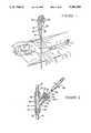
- FIG. 3is a perspective view of the first embodiment of the medical connector of the present invention which employs a slip-on/twist lock type means for securing the cap member to the port structure.
- FIG. 4is a cross-sectional view of the connector shown in FIG. 3 taken along line 4--4 of FIG. 3.
- FIG. 4ais a perspective view showing how the cap member prevents needle sticks.
- FIG. 5is a perspective view of the second embodiment of the medical connector of the present invention which employs a snap-on type means for securing the cap member to the port structure.
- FIG. 6is a cross-sectional view of the second embodiment of the medical connector of the present invention which employs a snap-on type means for securing the cap member to the port structure.
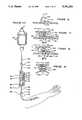
- FIG. 7is an exploded perspective view of the third embodiment of the medical connector of the present invention which employs a snap-on type means for securing the cap member to the port structure.
- FIG. 8is a side elevational view, with sections broken away, of the embodiment shown in FIG. 7.
- the handle of the locking mechanism attached to the cap memberjust engages the lip of the port structure.
- FIG. 9is the same view as shown in FIG. 8, except the handle of the locking mechanism is flexed and just about to snap into locking engagement with the lip of the port structure.
- FIG. 10is the same view as shown in FIGS. 8 and 9, except the handle of the locking mechanism is now engaging the lip of the port structure in the locking position.
- FIG. 10ais the same view as shown in FIGS. 8, 9 and 10, except the handle of the locking mechanism is flexed to permit removal of the cap member from the port structure.
- FIG. 11is a top plan view of the cap member.
- FIG. 12is a bottom view of the handle of the locking mechanism shown in FIGS. 8 through 11.
- FIG. 13is a side elevational view of the handle of the locking mechanism.
- FIG. 14is a side elevational view of the cap member with the handle of the locking mechanism removed.
- FIG. 15is a top plan view of the cap member with the handle of the locking mechanism removed.
- FIG. 16is an enlarged cross-sectional view of a portion of the hinge of the locking mechanism.
- FIG. 17is an enlarged cross-sectional view of the position of the handle just prior to being secured to the cap member.
- FIG. 18is a cross-sectional view similar to that shown in FIG. 17 depicting the handle coupled to the cap member.
- FIG. 19is a cross-sectional view taken along line 19--19 of FIG. 18.
- FIG. 20is a perspective view showing the medical connector of FIG. 7 having one end coupled to a tube extending from a patient's arm and another end coupled to a tube extending from a container holding medication.
- FIG. 21is a perspective view of a medical connector like that shown in FIG. 7, except the port structure has the lip which engages the handle of the locking mechanism as an integral part of a conventional piggyback connector.
- FIG. 22is a schematic view showing a medical connector of the type shown in FIG. 7 designed to introduce medication into a patient's chest.
- FIG. 23is a perspective view of a fourth embodiment of the medical connector of this invention which employs a slip-on/twist lock type means for securing the cap member to the post structure.
- FIG. 24is an enlarged cross-sectional view taken along line 24--24 of FIG. 23, showing the cap member being connected to the sealed entry port structure.
- FIG. 25is a perspective view of the fifth embodiment of the medical connector of the present invention which employs a twist lock means for securing the cap member to a port structure.
- FIG. 25ais a planar view of the distal end of the embodiment shown in FIG. 25 with the locking collar in the open position.
- FIG. 25bis a planar view of the distal end of the embodiment shown in FIG. 25 with the locking collar in the closed, locked position.
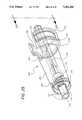
- FIG. 26is an exploded elevational view of the embodiment shown in FIG. 25.
- FIG. 27is a perspective view of the cap member of the embodiment shown in FIG. 25, with the locking collar in the open position.
- FIG. 28is a perspective view of the cap member of the embodiment shown in FIG. 25, with the locking collar in closed, locked position.
- the current way of intravenously introducing parenteral liquid into a patientis by the conventional feeding system 10.
- This feeding system 10includes a container 12 for the parenteral liquid, a tube 14 extending from the container and connected to a Y or "piggyback" connector 16, and a tube 18 from the piggyback connector to a needle (not shown) inserted into a vein of the patient.
- the needleis taped to the patient so that movement of the patient will not result in the needle being pulled from the patient's vein.
- medication from the container 20is introduced through the piggyback connector 16 into the parenteral liquid flowing through the feeding system 10.
- This piggyback connector 16consists of two tubular conduits 22 and 24 which merge into a third tubular conduit 26.
- the tubing 14 from the container 12 of parenteral liquidis inserted into the inlet port 28 of the conduit 22 and secured in position, for example, by an adhesive which bonds the external surface of this tube to the internal wall surface of the conduit.
- the tube 18is secured to the outlet port 32 of the piggyback connector. This tube 18 is inserted into the outlet port 32 until it abuts a stop 34 in the internal wall of the conduit.
- This tube 18is secured by an adhesive to the internal wall of the conduit 26.
- the sealed entry port structure of the conventional feeding system 10is provided by the branch conduit 24 which has a standard latex rubber seal 36 at its inlet port 38 to seal this port. Consequently, bacteria cannot enter the piggyback connector 16 via the inlet port 38 because of the seal 36.
- This seal 36is of conventional design and includes coaxial annular aprons 40 and 42 which fit over the conduit wall 24a and grip the external and internal wall surfaces to hold the seal securely to the conduit 24.
- a suitable sealmay be obtained from the West Company of Phoenixville, Pennsylvania.
- the medicationis introduced into the parenteral liquid flowing through the piggyback connector 16 by a needle 44 which is inserted through the central part of the seal 36 into the branch conduit 24.
- This needle 44is connected by a suitable connector 46 to a tube 48 which is connected to the container 20 (FIG. 1) for the medication.
- the medicationis drawn into this stream of liquid, flowing from the container 20 via the tube 48 and through the open tip or end 44a of the needle 44 into the parenteral liquid.
- the needle 44may be pulled from the seal 36. If this occurs, the latex seal 36 has sufficient resiliency to close off the hole in the seal produced by the needle 44. The parenteral liquid will continue to flow into the patient's system, but the necessary medication is no longer being introduced into it. The consequences of this condition are very grave and, if this condition is unnoticed by the nurse, it could result in the death of the patient or serious complications in the patient's treatment. Even if the nurse notices that the needle 44 has been removed from the seal 36 and reinserts it into the seal, it is possible that the needle has been contaminated with bacteria.
- the use of such a contaminated needle 44is unacceptable, but nevertheless this sometimes happens.
- the needle 44may be taped to the conduit 24, and many hospitals instruct nurses to do this. When this task is done, the needle 44 is secured, but cannot be conveniently removed and then reinserted. And even when taping the needle 44, if this is not done carefully, the needle may still be contaminated by the nurse touching the needle or the tape being contaminated. Also, because the nurse holds the conduit 24 with one hand while inserting the needle 44, the nurse may accidentally stick the needle directly into the hand holding this conduit, or stick the needle through the conduit wall 24a into this hand.
- the first embodiment of this invention, connector 49employs a cap member 50 housing deep within the needle 44.
- the cap member 50is secured by a slip-on/twist lock type of locking mechanism to the piggyback connector 16 so that movement of the patient does not result in the needle 44 being pulled from the seal 36.
- the parenteral liquidis introduced via the conduit 24, and the conduit 22 carries the seal 36 that covers the inlet port 28.
- this sealed conduit 28constitutes the entry port structure 27.
- the cap member 50is detachably secured to the entry port structure 27, with the needle 44 penetrating the seal center of the seal 36 when the cap member 50 mates with the port structure 27.
- the cap member 50comprises a cylindrical connector section 56 having a hollow interior forming the chamber or cavity 52 housing the needle 44.
- This needle 44is disposed lengthwise along the longitudinal axis of the cavity 52 and is centrally located.
- the cavity 52has an open mouth 52a which allows the cap member to be seated over the port structure 27.
- the mouth 52ais constricted so that, as illustrated in FIG. 4a, it prevents the little finger of a typical adult user from being inserted into the cavity 52.
- the tip or end 44a of the needleis safely displaced inwardly from the open mouth 52a so that even if the user intentionally inserted his or her finger into the open mouth, the tip of the needle would not stick this finger.
- the open mouth 52ahas a maximum width of no greater than about one centimeter, and the minimum distance between the mouth 52a and the tip 44a is about one centimeter.
- the locking mechanismincludes the threads 69a formed in the end 54 of the interior cavity wall 55 and the threads 69b in the exterior wall of the conduit 22. These threads 69a and 69b engage upon connection of the cap member 50 to the port structure 27 by screwing the cap member to the conduit 22.
- the top of the cap member 50has a pair of outwardly extending wings 58 which facilitate screwing the cap member 50 to the conduit 22. As this is done, the interior wall 55, sliding over the exterior surface of the conduit 22, guides the needle 44 so that it penetrates the center of the seal 36.
- the threads 69bcould be lowered further beneath the seal so that the cap member would fit telescopically over the conduit 22 and then be screwed into position.
- the cap member 50, serving as the female component, and conduit 22, serving as the male componentmate in a male-female relationship, with the needle 44 always being housed safely within the center of the cavity in an unexposed condition and positioned to pierce the center of the seal 36.
- a spindle 59is provided to enable the cap member 50 to be screwed onto the port structure 27 without twisting the tube 48.
- This spindle 59is received within an opening 61 within the cap member 50.
- the body of the spindle 59has a cylindrical neck section with a groove 63 in an end which protrudes from the opening 61.
- the cylindrical bodyexpands outwardly slightly to provide a shoulder 65 which engages a stop 66 when the spindle 59 is placed in the opening, and a TRU seal O-ring 67 is received in the groove 63 to hold the spindle in position but allowing the cap member to revolve about the spindle as it is screwed onto the port structure 27.
- a passageway 60Along the longitudinal axis of the spindle 59 is a passageway 60.
- the tube 48 from the container 20 holding the medicationis inserted into the one end 60a of the passageway 60 and is bonded to the internal surface of this passageway, for example, by means of an adhesive.
- the other end 60b of the passagewayterminates in a threaded connector section 62 to which the needle 44 is secured.
- This needlehas an adapter 64 which has an internal thread which engages the threads of the connector section 62.
- the needle 44extends outwardly from this adapter 64.
- the needle 44is held secure to the piggyback connector 16, penetrating the center of the seal 56 with its point 44a safely displaced away from the inside wall 55 of the conduit 22.
- This connector 49embodies many of the features of this invention.
- the cap member 50safely houses the needle 44, and the threads on the guiding walls provide means for detachably securing the cap member to the port structure without taping. But it has several components, and therefore is costly to manufacture, it is time consuming to screw the cap member 50 to the port structure, and it does not provide an audible signal when the cap member is safely secured to the port structure. This later feature is provided by the second and third embodiments of this invention.
- FIGS. 5 and 6The second embodiment of the present invention, connector 71, is shown in FIGS. 5 and 6.
- a cap member 70similar to cap member 50, is simply snapped onto the piggyback connector 16.
- the snap-on type locking mechanism of this connector 71is easier to use and less costly to manufacture than the slip-on/twist type of the first embodiment.
- the cap member 70includes a hollow cylindrical element 72 which carries on its exterior two clips 74 which have catch tips 76 that snap into a groove 78 in the external wall of the conduit 22.
- the clips 74are mounted by hinges 75 to the element 72, and are integral with the element 72.
- a plug assembly 80carries the tubing 48 and the needle 44, which is mounted on an adapter 64 such as shown in FIG. 4. This plug assembly 80 is glued or otherwise bonded to the open end of the cylindrical member 72.
- the cap member 70, including clips 74 and hinges 75,are molded from the same material, for example, nylon, which is a material having the desired resiliency.
- the clips 74bend outwardly slightly and, when the catch tips 76 of the clips are opposite the groove 78, the clips snap in place as shown in solid lines in FIG. 6.
- the centrally mounted needle 44is guided into the center of the seal 36 by the cap member 70 which, like a telescope, slides over the tubular conduit 22.
- shoulder 82which serves as a stop to limit the movement of the cap member 70. This shoulder 82 brings the catch tips 76 of the clips into registration with the groove 78.
- the hinges 75being of the same material as the clips 74, provide an internal bias or spring action due to the resiliency of the material from which these clips and hinges are made.
- the clips 74snap into a locking position, locking the cap member to the conduit 22 when the catch tips 76 are in registration with the groove 78.
- the clips 74are simply depressed and the cap member 70 is removed.
- the third embodiment of this invention, connector 90includes a sealed port structure 91 and a cap member 92 having a locking mechanism 94 for detachably securing the cap member 92 to the port structure 91.
- the cap member 92is similar to the cap members of the other embodiments and houses within its cavity 92a (FIG. 8) the needle 44.
- the cavity 92ahas a tapered side wall 93 to better direct the needle 44 into the center of the seal 36.
- the port structure 91is a tubular conduit 102 having, at one end, a reduced diameter nipple 104 over which the seal 36 fits and, at the other end, a tapered barrel 103.
- the seal 36is of the same type employed in conventional devices such as shown in FIG. 2. Material is removed from the barrel 103 to reduce cost. This results in the formation of flutes 103a in the barrel 103.
- a handle 96which is a component of the locking mechanism 94, engages this lip 106.
- the handle 96is hinged to the body 98 of the cap member by a two component hinge 100.
- a hook 114is one component of the hinge 100 and the other component of the hinge is a crossrod 108 (FIG. 18) carried by the handle 96.
- the hook 114projects outwardly from the body 98 of the cap member and has adjacent to it a ramp 116 which, as shown in FIG. 18, holds the crossrod 108 when the handle 96 is attached to the body of the cap member.
- a section of the crossrod 108is cut away to provide a miter slot 118 which engages the ramp 116.
- the handle 96is best shown in FIGS. 12 and 13. It has a pair of spaced apart plates 110 and 112 extending downwardly from the underside of the handle and the crossrod 108 is disposed between these plates, with the opposed ends of the crossrod being integral with the plates. Opposite the crossrod 108 and parallel to it is a third plate 120, which is integral with the underside of the handle 96 and is at a right angle to and connects with the forward ends of the plates 110 and 112. Disposed on the underside of the handle 96 between the catch tip 122 and the plate 120 is a clapper bar 126. The clapper bar 126 produces the "click" sound when it strikes the body 98 of the cap member.
- This clapper bar 126extends away from the plate 120 at a right angle and is integral, at one end of the handle, with the catch tip 122 and, at its opposite end, with the plate 120.
- the leading edge 124 of the catch tip 122is beveled to facilitate the slippage of this tip up and over the lip 106, which is also beveled.
- a leaf spring 130At the rear end of the handle 96 is a leaf spring 130 which has one end free and its opposed end integral with the handle 96.
- FIG. 12At the free end of the leaf spring 130 are two spaced apart tracks 132 and 134 (FIG. 12).
- a finger 136 on the body 98 of the cap memberis received within the channel 138 between the tracks 132 and 134.
- On the underside of the handle 96are two downwardly projecting reinforcing strips 140 and 142 (FIG. 12) which provide structural rigidity to the handle.
- FIGS. 16 through 19The way in which the handle 96 is pivotably connected to the cap member 92 by the two component hinge 100 is illustrated by FIGS. 16 through 19.
- To attach this handle 96 to the body 98 of the cap memberfirst one positions the handle over the body of the cap member opposite the hook 114 and then moves the handle into contact with the cap member so that the crossrod 108 touches the rear end of the ramp 116. The spring 130 is depressed at this time.
- the handle 96is moved towards the left, as shown in FIG. 17, with the crossrod 108 sliding up the ramp 116 until it engages the leading edge 140 of the hook 114.
- the dimension between the edge 142 of the ramp 116 and the edge 140 of the hook 114is less than the diameter of the crossrod 108.
- the hook 14must flex slightly upwardly in a counterclockwise direction, as viewed in FIG. 17, until the crossrod 108 clears the edge 142 of the ramp and snaps into the position shown in FIG. 18.
- the hook 114thus returns to the unflexed condition shown in FIG. 18, wrapping around the crossrod 108.
- the miter slot 118then engages the edge 142 of the ramp, with this edge abutting the junction 118a of the slot 118 (FIG. 18) .
- the ramp 116thus holds the crossrod 108 in position, preventing the handle from becoming dislodged from the hook 114 and preventing the handle 96 from tilting to-and-fro about its longitudinal axis.
- the finger 136slips into the channel 138 between the tracks 132 and 134 and holds the rear end of the handle so that it does not tend to move laterally.
- the handle 96is, however, free to pivot about the hinge 100.
- the two component hinge 100does not break due to fatigue.
- the handle 96may be moved between a locked position (FIG. 10) and unlocked position (FIG. 8) as often as one wishes without breaking.
- the handle 96coating with the body 98 of the cap member 92, generates a "click" sound when the cap member is locked to the port structure 91.
- This "click" soundoccurs when the handle 96 moves between the flexed position shown in FIG. 9 and the locked position shown in FIG. 10.
- the connector 90is highly reliable under actual hospital working conditions, and the way connector 90 is used is best shown in FIGS. 8 through 10a.
- the nurseinserts the end of the port structure carrying the seal 36 into the open mouth 93 of the cap member 92 to bring the lip 106 into engagement with the catch tip 122 of the handle 96 as shown in FIG. 8.
- the tapered side wall 93 of the cap member and the tapered barrel 103slide along each other to direct the needle 44 into the center of the seal 36.
- the beveled edge 124 of the catch tiprides over the beveled lip 106 until the lip just engages the underside edge of this tip as shown in FIG. 9. This causes the handle 96 to rotate in a clockwise direction as viewed in FIG.
- This "click” soundis the audible signal which the nurse may rely upon to indicate that the cap member 96 is locked to the port structure 91. Under certain hospital conditions, particularly in the intensive care unit where there is not a great deal of light, this is an important feature because it provides additional assurance that the cap member 92 is locked to the port structure 91.
- the connector 90is made entirely of a transparent plastic.
- a transparent plasticis preferred because this allows the nurse to see that the needle 44 is correctly inserted into the seal 36, and thus provides additional safety.
- the use of plasticmakes the connector 90 a low cost, disposable item.
- the plastic most suitableis a polycarbonate made by Cyrolite Industries in Azusa, California sold under the trade name CYROLITE. This plastic, which is commonly employed to make medical devices, has been approved for such uses by the United States Federal Drug Administration.
- the connector 90is particularly adapted to be used in a variety of different applications.
- itmay be connected directly in line with a container 144 of medication to be supplied intravenously to a patient.
- the cap member 92has a tube 146 extending from it which has at its one end a male component 148 of a conventional luer lock connector.
- This male component 148engages and locks with a mating female luer component 150 attached to the end of a line 146 extending from the container 144.
- the port structure 91has extending from it a tube 154 which has at its end a female luer component 158 of a second luer lock connector.
- the male component 156 of this second luer lock connectoris attached to the end of a tube 160 that is connected to a needle inserted into the vein of the patient.
- the luer lock connectorsmay be obtained from Burron Medical, Inc. in Bethlehem, Pennsylvania.
- FIG. 21illustrates the connector 90 integrated into a conventional piggyback connector 162.
- the branch line 164 from the piggyback connector 162has attached to it and integral therewith the port structure 91 including the lip 106 that engages the catch tip 122 of the locking mechanism 94.
- a conventional feeding system 10 employing a piggyback connectormay be modified by simply including a lip 106 adjacent the seal 36. This lip 106 will then serve as the site for detachably connecting the cap member 92 to the piggyback connector 162.
- the connector 90also lends itself to be used with central venous catheters which are inserted into the chest of the patient. Frequently, patients under home care use such catheters, and consequently, even simpler and safer devices and techniques must be employed. However, a serious problem with such catheters is the way the ends of the lumens or tubes 166 and 168 extending from the patient are sealed. Presently, the ends of these tubes 166 and 168 are sealed using conventional luer locks. When it is time for the patient or the nurse to introduce medication into the catheter, an intermediate portion of the tubes 166 and 168 must be clamped while being connected to the source of medication so that air is not drawn into the blood stream of the patient.
- the connector system 90overcomes these difficulties by simply having at each of the respective ends of the tubes 166 and 168 port structures 91.
- the patientneeds medication, he or she simply connects two of the cap members 92 to the respective port structures 91 and when finished, disconnects the cap members.
- the medicationis fed by the needles 44 through the seals 36 and into the respective tubes 166 and 168.
- the cap members 92when detached, withdraw the needles 44 from the seals 36, which are self-sealing.
- I the nursedoes not need to clamp off the tubes 166 and 168 nor is periodic repair of the tubes required.
- connector 90is both safer and more convenient to use than the conventional central venous catheters.
- the connector 90is also adapted to be used repeatedly without damaging the seal 36. Thus, it is even more suitable for applications as illustrated in FIG. 22 than conventional devices because of the accuracy with which the needle 44 may be repeatedly directed into the center of the seal 36.
- the sealwill have numerous holes in it and begin to develop a "swiss cheese"-like appearance.
- a coreis cut away from the seal by several of these holes interconnecting, rendering the seal useless because it is no longer self-sealing. Consequently, the seal would have a very short life.
- the cap member 92 and port structure 91will be precision-made parts. Consequently, with repeated use, the needle 44 will essentially always penetrate the same hole in the seal 36, thus avoiding the "coring" problem.
- FIGS. 23 and 24The fourth embodiment of this invention, the connector 170, is illustrated by FIGS. 23 and 24.
- the port structure 172is similar to that shown in the other embodiments except it has a pair of pins on opposite sides of its body 178 which coact with J-type slits 180 and 182 in the sidewall of a cap member 183 housing the needle 44.
- J-type slits 180 and 182are opposed to each other and provide a guideway for the pins 174 and 176 which slide along these slits as the port structure 172 matingly engages the cap member 183.
- the nursealigns the port structure 172 with the open mouth 183a of the cap member so that the pins 174 and 176 are in alignment with the entryway to the J-type slits 180 and 182. Then the nurse pushes the port structure 172 into the open mouth 183a, sliding the port structure into the cavity within the cap member 183. The pins 174 and 176 first engage the entryway of the J-type slits 180 and 182 and then slide along the slits until they reach the base of the slits.
- the nursetwists or rotates the cap member 183 and port structure 172 in counter-rotating directions so that the pins 174 and 176 will then slide respectively into the hooks 180a and 182a of the slits and be secured.
- This embodimentdoes not provide an audible signal upon locking the cap member 183 to the port structure 172, but is very economical to manufacture.
- the cap memberprovides several functions in a single structure. (We will no longer refer by number to any one of the components of the invention since we are now discussing in general how the cap member and port structure function to provide the attributes of safety and convenience.)
- the cap membersurrounds the needle and provides a housing in which the needle is lodged safely so that needle sticks are avoided.
- the needleis so lodged within the housing, if the nurse did, for example, lay the cap member on the patient's bed, the needle would not come into direct contact with the bedding which might be infested with harmful bacteria.
- this arrangement of the needle deep within the cavity in the cap memberprovides protection for the patient against bacterial contamination and protection for the nurse against accidental needle sticks.
- the port structurealso provides more than one function.
- Firstit serves as the site to attach the cap member, and, by means of a simple locking element such as a lip, thread, groove, pin or the like, provides an economical way to modify the conventional piggyback connector so that it may be used with the cap member.
- Second, the combination of a self-sealing seal and adjacent element that locks the cap memberprovides a simple way to modify connectors so that they have enhanced safety and convenience.
- the cap member and port structurefunction in combination to direct the needle into the center of the seal, lock these pieces together and enable quick connection.
- the nurse or patientsimply aligns the sealed end of the port structure with the open mouth of the cap member and pushes the two pieces together.
- the internal wall of the cap member and the exterior wall of the port structureengage to align the two pieces so that their respective axes coincide, guiding the needle into the center of the seal as they are pushed together. Consequently, the needle does not scrape the inside wall of the port structure so that particles of plastic are not introduced into the patient's blood stream and the coring problem is virtually eliminated.
- the cap member and port structureseach carry elements of a locking mechanism which engage and lock the pieces together when the needle has pierced the seal, preventing accidental disconnect.
- the first through third embodiments of this inventionare very quickly connected because no extra step is required to align the cap member and port structure. All that the nurse need do is insert the port structure into the open mouth without any special concern for their relative positions and, when using the second and third embodiments, simply push these two pieces together until the locking mechanism engages.
- the extra step of rotating the two pieces relative to each otheris required to engage the locking mechanism.
- the pinsmust also first be aligned with the entryways to the J-slits prior to pushing the port structure into the cavity in the cap member.
- this inventionmay be used under normal hospital conditions without creating any additional work for the nurse, while substantially reducing the likelihood of harm to the patient due to carelessness and protecting the nurse against infection and making his or her job easier and faster.
- the safety connector locking devicecontain a collar or ring-type rotating lock mechanism to secure the junction between the flexible intravenous drip tubing extending from the intravenous solution container and the "Y" or piggyback connector.
- the type of lock mechanism contemplated in this fifth embodiment of the inventionis advantageously less expensive to manufacture and simpler to use than the previous embodiments.
- the device, of the fifth embodimentprevents needle sticks, protects the junction from contamination by adventitious agents and generates a "click" sound upon lock engagement.
- FIGS. 25-28illustrate a preferred safety connector locking device.
- FIG. 25illustrates perspective view in elevation of a preferred embodiment of the safety connector locking device 200.
- the locking device 200is designed to fit over a "Y" or piggyback connector, such as the piggyback connector 16 diagrammed in association with FIG. 3.
- the safety locking devicecomprises a tubular body or cap member 202, an intravenous drip attachment tube 216 and a rotatable locking collar 212.
- the cap member 202forms a hollow tubular chamber 218 that contains a needle 210 in open communication with a second chamber 214 to provide an open channel with the intravenous drip attachment tube 216. Fluid passes from the effluent intravenous drip tub 216 into chamber 214, through needle 210, and during engagement, into an influent port of the "Y" connector (not shown).
- the cap member 202is telescopically tapered with the widest portion at the locking collar 212 at the distal end of the device and narrowing toward the intravenous drip attachment tube 216 at the proximal end.
- the tapered cap member 202serves to guide the piggyback connector conduit 22 (see FIG. 4) or branch port of the "Y" connector into the tubular chamber 218 so that the needle 210 pierces the septum or seal 36 on the conduit to actively engage the entry port of conduit 22, as depicted in FIG. 4, with the needle attachment region.
- the junction between the conduit and the safety connector device 200is protected by the cap member 202 from exposure to adventitious agents.
- the needle 210is suspended from the needle attachment cap 220 such that the needle is centrally located with the tubular chamber.
- the overall length of the tubular chamberis such that the needle is recessed into the chamber.
- the widest portion of the cap member 202is preferably narrow enough in cross sectional diameter and the needle 202 is recessed sufficiently such that the little finger of a typical adult user cannot enter the tubular chamber and contact the suspended needle.
- the widest portion at the opening, of the tubular chamber 218is no greater than about one centimeter and the minimum distance between the opening and the needle tip 210a is at least about one centimeter.
- varying conduit or branch port diameters of the "Y" connector with which the apparatus is usedmay necessitate slight changes in the diameter of the apparatus 200.
- the tubular intravenous drip IV attachment tube 216there are two attachment barbs 222 that extend outwardly from the drip attachment tube. These barbs 222 provide attachment holds for the flexible intravenous drip tubing that extends from the medication container and ends at the safety connector locking device (see FIG. 1) .
- the barbs 222form a male luer connector for attachment onto intravenous tubing, however other attachment means are contemplated. These would be well known to those individuals with skill in the art, thus no additional discussion is required. It is further contemplated that an adhesive could be used to strengthen the attachment between the flexible intravenous drip tubing and attachment tube 216.
- the second open chamber 214permits the continuous flow of liquid from the medication chamber through the safety connector and into the Y connector. Dashed line 215 indicates the continuous opening provided from tubular chamber 214 through the distal region of the cap member 202.
- intravenous IV drip attachment tube 216is connected to the upper rim 224 of cap member 202 and is situated at the proximal end of the apparatus.
- piggyback connector locking device 212is associated with the lower rim 230 or distal portion of cap member 202.
- Intravenous drip attachment tube 216enters through the upper rim of the cap member into tubular chamber 218.
- the attachment tube 216telescopically narrows within the tubular chamber toward needle 210 to form a needle attachment site.
- Needle attachment cap 220is connected to needle 210 at its proximal end.
- the needle attachment siteis an extension of the intravenous drip attachment tube that extends into tubular chamber 218.
- Needle attachment cap 220preferably connects to attachment tube 216 by a luer-lock fitting. Threads 226 within the tubular chamber facilitate the fitting between the cap member 202 and needle 210. It is additionally contemplated that an adhesive could be used to strengthen the fitting between the needle attachment cap and the distal portion of the attachment tube.
- cap member archway 204Along the length of the cap member and extending toward the distal rim 230 is cap member archway 204.
- the archwaycomprises a cut out section along the lower wall of the cap member casing to provide a channel or slot for one arm of the "Y" connector.
- Piggyback connectorsoften are formed in the shape of a "Y”. These connectors have a straight tubular portion and a lateral arm extending outward.
- the "Y"has two arms or branches joining at a crook to form a "V". Each branch forms an influent fluid conduit that is sealed by a pierceable septum. A stalk extending from the crook joins both conduits into a single influent fluid line.
- one arm of the "Y"is inserted into the cap member of the disclosed invention.
- Archway 204forms a channel or slot for the adjacent arm.
- the archwayfits into the crook to create a snug fit such that the proximal portion of the archway sits within the crook formed by the two branches of the Y. This permits the distal end of the safety connector to extend around the adjacent arm and extend down the stalk of the connector.
- a rotatable locking collar 212that forms a twistable annular collar that glides about the lower rim of the cap member.
- FIG. 26is an exploded elevational view of FIG. 25.
- Cap member 202is separated from the rotatable locking collar 212.
- the cap member 202has a shoulder extension 232 that further broadens the telescopic expansion of the cap member.
- the width of the lower edge 234 of the shoulder 232defines the final external width of the safety connector device.
- the distance along the cap member between the lower edge of the shoulder and the distal rim of the cap member 230defines the height of the rotatable locking collar 212.
- the collar locking devicecomprises an essentially circular ring that is preferably manufactured from the same material as the cap member.
- the first cut out region of the locking collardefined as the area between edges 236 and 240, is preferably equal in width to the cap member archway 204 such that in the open or first position (see FIG. 27), the collar and archway are superimposed.
- the rotatable locking collaris sized just larger than the distal portion of the cap member to permit rotation about a common axis.
- the collar locking devicehas a second cut out notch 242 that will be discussed in further detail below.
- the distal rim 230 of the cap memberhas an annular shoulder or slight lip extension 244 that serves as a distal rotation guide for the collar locking device.
- a second rotational guide 246is preferably formed as a groove immediately below the lower edge 234 of the cap member shoulder 232.
- a locking bar 248is provided along one edge of the archway opening on the cap member and a complementary locking bar 250 is additionally positioned along edge 236 of the collar locking device 212.
- the collar locking deviceis designed to fit beneath cap member shoulder edge 234 along the rotational guides such that it can rotate around the distal region of the cap member.
- Annular flange 243extends radially inward from the collar locking device and follows the cap member lip extension guide 244.
- rotation from a first positionis unidirectional toward edge 240 and is restricted by a radially outward extending stop 247 located circumferentially on the outer surface of rim 230.
- the collaris permitted to rotate within a recessed region 245 of annular flange 243.
- locking bar 248 on the cap memberis opposite complementary locking bar 250 and outward extending stop 247 is positioned along the recessed region 245 proximal to stop bar 250.
- the collar locking deviceis rotated toward locking bar 248 (see FIGS. 25b and 28). Additional rotational pressure is required to pass complementary locking bar 250 past locking bar 248 to produce an audible "click". This noise tells the operator that the device is positioned correctly on the "Y" connector.
- a recess 248 adjacent to locking bar 250receives the bar 250 and the outward extending stop 247 moves to a position along recessed region 245 proximal to collar edge 240.
- the cut out notch 242moves beneath archway 204 to provide a locked oval channel or slot to accommodate the arm of the Y connector not actively engaged by the disclosed invention.
- the rotatable collar 212is provided with a handle 249 which allows the user of the device to easily grasp the collar 212 for rotation in accordance with the foregoing description.
- the handle 249comprises a raised ridge on the collar 212.
- other handlessuch as a tab extending from the collar 212, are contemplated within the context of the present invention.
- the needle attachment cap 220is preferably supplied with two or more barbs 252. These engage needle attachment threads 226 in a luer-lock type locking mechanism.
- the apparatusadditionally comprises a needle sheath 254.
- the safety connector locking device 200is provided for use as a sterile product that could additionally be provided with or without sterile intravenous drip tubing.
- the device 200is removed from its sterile packaging.
- Tubingis connected via barbs 222 onto the intravenous drip attachment tube.
- Needle 210is secured to the casing chamber portion of the attachment tube 216 by turning the protective sheath 254 to the right.
- the needle sheath 254is removed by pulling outward.
- the pierceable septum over the "Y" connector conduitis swabbed with alcohol to decontaminate the puncture site.
- the cap memberis slid over the branch of the Y connector that has been swabbed.
- Archway 204is aligned with the crook of the "Y" connector and the cap member is pushed onto the arm of the Y connector as far as it will go or until the collar locking device can be rotated to form an enclosure around the stalk of the "Y” connector.
- Needle 210should pierce the septum during the connection procedure.
- the collar 212is rotated until it locks.
- a "click" soundwill be heard upon locking due to the locking bar 250 going into the recess 248.
- the drip medicationis allowed to flush through the apparatus prior to connecting the intravenous drip to the patient's arm. However this is not always possible, particularly when the intravenous connection is already in place. Thus, the prior flushing step can be omitted.
- the addition of the safety connector to the "Y" connectorcan be accomplished quickly and precisely without risk of needle puncture or improper insertion in to the arm conduit since the telescopic design guides the cap member to the proper location and the cap member covers the needle tip.
- the devicehas minimum removable pieces and is therefore more cost effective to manufacture. It is easy to use and has a low risk for contamination and needle sticks. An audible signal insures that the lock mechanism is in place.
- our connectoris safe because (a) the needle is recessed deeply within the cap member and, therefore, is not likely to be contaminated by bacteria; (b) the cap member and port structure upon engagement guide the needle into the center of the seal, avoiding scraping particles from the inside wall of the port structure; (c) the cap member, housing the needle safely within it, protects the nurse against needle sticks; (d) the locking of the cap member and port structure together prevents accidental disconnects; and (e) the "click" signals the nurse when the connector system is locked securely in position.
- Our connectoris convenient to use because (a) the walls of the cap member and port structure, interacting with each other, provide a guideway for quick connection; (b) the locking mechanism eliminates the burdensome and time consuming task of taping; and (c) the connector is very simple to use so that it is ideal for home care of patients.
Landscapes
- Health & Medical Sciences (AREA)
- Heart & Thoracic Surgery (AREA)
- Pulmonology (AREA)
- Engineering & Computer Science (AREA)
- Anesthesiology (AREA)
- Biomedical Technology (AREA)
- Hematology (AREA)
- Life Sciences & Earth Sciences (AREA)
- Animal Behavior & Ethology (AREA)
- General Health & Medical Sciences (AREA)
- Public Health (AREA)
- Veterinary Medicine (AREA)
- Infusion, Injection, And Reservoir Apparatuses (AREA)
- Materials For Medical Uses (AREA)
- External Artificial Organs (AREA)
Abstract
Description
Claims (2)
Priority Applications (13)
| Application Number | Priority Date | Filing Date | Title |
|---|---|---|---|
| US07/747,010US5281206A (en) | 1983-01-24 | 1991-08-19 | Needle connector with rotatable collar |
| EP92915583AEP0599866B1 (en) | 1991-08-19 | 1992-06-23 | Medical connector |
| AU22682/92AAU2268292A (en) | 1991-08-19 | 1992-06-23 | Medical connector |
| ES92915583TES2114944T3 (en) | 1991-08-19 | 1992-06-23 | MEDICAL CONNECTOR. |
| AT92915583TATE162953T1 (en) | 1991-08-19 | 1992-06-23 | MEDICAL CLUTCH |
| DK92915583TDK0599866T3 (en) | 1991-08-19 | 1992-06-23 | Medical connector |
| JP50428393AJP3150696B2 (en) | 1991-08-19 | 1992-06-23 | Medical connector |
| DE69224391TDE69224391T2 (en) | 1991-08-19 | 1992-06-23 | MEDICAL CLUTCH |
| CA002114848ACA2114848C (en) | 1991-08-19 | 1992-06-23 | Medical connector |
| HK98109198AHK1008419A1 (en) | 1991-08-19 | 1992-06-23 | Medical connector |
| PCT/US1992/005260WO1993003787A1 (en) | 1991-08-19 | 1992-06-23 | Medical connector |
| US08/108,441US5330450A (en) | 1983-01-24 | 1993-08-17 | Medical connector |
| AU61930/96AAU6193096A (en) | 1991-08-19 | 1996-08-07 | Medical connector |
Applications Claiming Priority (5)
| Application Number | Priority Date | Filing Date | Title |
|---|---|---|---|
| US46058583A | 1983-01-24 | 1983-01-24 | |
| US54324883A | 1983-10-19 | 1983-10-19 | |
| US60667984A | 1984-05-03 | 1984-05-03 | |
| US34619387A | 1987-01-09 | 1987-01-09 | |
| US07/747,010US5281206A (en) | 1983-01-24 | 1991-08-19 | Needle connector with rotatable collar |
Related Parent Applications (1)
| Application Number | Title | Priority Date | Filing Date |
|---|---|---|---|
| US34619387AContinuation-In-Part | 1983-01-24 | 1987-01-09 |
Related Child Applications (1)
| Application Number | Title | Priority Date | Filing Date |
|---|---|---|---|
| US08/108,441ContinuationUS5330450A (en) | 1983-01-24 | 1993-08-17 | Medical connector |
Publications (1)
| Publication Number | Publication Date |
|---|---|
| US5281206Atrue US5281206A (en) | 1994-01-25 |
Family
ID=25003301
Family Applications (1)
| Application Number | Title | Priority Date | Filing Date |
|---|---|---|---|
| US07/747,010Expired - LifetimeUS5281206A (en) | 1983-01-24 | 1991-08-19 | Needle connector with rotatable collar |
Country Status (11)
| Country | Link |
|---|---|
| US (1) | US5281206A (en) |
| EP (1) | EP0599866B1 (en) |
| JP (1) | JP3150696B2 (en) |
| AT (1) | ATE162953T1 (en) |
| AU (2) | AU2268292A (en) |
| CA (1) | CA2114848C (en) |
| DE (1) | DE69224391T2 (en) |
| DK (1) | DK0599866T3 (en) |
| ES (1) | ES2114944T3 (en) |
| HK (1) | HK1008419A1 (en) |
| WO (1) | WO1993003787A1 (en) |
Cited By (101)
| Publication number | Priority date | Publication date | Assignee | Title |
|---|---|---|---|---|
| WO1994023776A1 (en)* | 1993-04-14 | 1994-10-27 | Plassche Walter M Jr | Interventional needle having an automatically capping stylet |
| WO1994023775A1 (en)* | 1993-03-23 | 1994-10-27 | Abbott Laboratories | Securing collar for cannula connector |
| WO1994021103A3 (en)* | 1993-03-15 | 1994-12-08 | Abbott Lab | Luer adapter assembly for emergency syringe |
| US5437648A (en)* | 1992-11-23 | 1995-08-01 | Becton, Dickinson And Company | Locking safety needle assembly |
| USD363541S (en) | 1992-09-29 | 1995-10-24 | Maxxim Medical, Inc. | Rotating adapter for a catheter |
| US5462255A (en)* | 1993-11-19 | 1995-10-31 | Novoste Corporation | Automatic fluid control valve |
| US5496274A (en)* | 1992-11-23 | 1996-03-05 | Becton, Dickinson And Company | Locking safety needle assembly |
| US5545152A (en)* | 1994-10-28 | 1996-08-13 | Minimed Inc. | Quick-connect coupling for a medication infusion system |
| US5582600A (en)* | 1995-08-03 | 1996-12-10 | Baxter International Inc. | Transfer set connector with a locking lid and a method of using the same |
| US5632735A (en)* | 1992-09-29 | 1997-05-27 | Wyatt; Philip | Infusion apparatus |
| USD380262S (en)* | 1995-06-26 | 1997-06-24 | Minimed Inc. | Quick disconnect coupling |
| US5746215A (en)* | 1996-11-01 | 1998-05-05 | U.S. Medical Instruments, Inc. | IV infusion or collection device with extendable and retractable needle |
| US5806551A (en)* | 1993-11-19 | 1998-09-15 | Novoste Corporation | Automatic fluid control valve |
| WO1999013937A3 (en)* | 1997-09-15 | 1999-06-03 | Winfield Medical Inc | Needleless valve |
| US5989237A (en) | 1997-12-04 | 1999-11-23 | Baxter International Inc. | Sliding reconstitution device with seal |
| US6022339A (en) | 1998-09-15 | 2000-02-08 | Baxter International Inc. | Sliding reconstitution device for a diluent container |
| US6093183A (en)* | 1998-08-07 | 2000-07-25 | Pavkovich; Mary | Safety Intravenous connector |
| US6096024A (en)* | 1999-02-12 | 2000-08-01 | Becton Dickinson And Company | Blunt needle connector |
| US20020123736A1 (en)* | 1998-09-15 | 2002-09-05 | Fowles Thomas A. | Sliding reconstitution device for a diluent container |
| US20030083518A1 (en)* | 2001-06-27 | 2003-05-01 | Varghese John | Substituted alcohols useful in treatment of Alzheimer's disease |
| US6582415B1 (en) | 1998-09-15 | 2003-06-24 | Thomas A. Fowles | Sliding reconstitution device for a diluent container |
| US20030176852A1 (en)* | 2001-01-05 | 2003-09-18 | Lynch George R | Low profile pivoting joint infusion assembly |
| US20030216686A1 (en)* | 2002-03-08 | 2003-11-20 | Applied Diabetes Research, Inc. | Low profile, pivotal connection infusion assembly |
| US20040073174A1 (en)* | 1991-12-18 | 2004-04-15 | Lopez George A. | Medical valve and method of use |
| US20040199139A1 (en)* | 1998-09-15 | 2004-10-07 | Fowles Thomas A. | Sliding reconstitution device for a diluent container |
| US20040241041A1 (en)* | 1998-09-15 | 2004-12-02 | Archie Woodworth | Apparatus and method for fabricating a reconstitution assembly |
| US20050015075A1 (en)* | 2003-07-14 | 2005-01-20 | B & D Research And Development Inc. | Coupling device for medical lines |
| US20050133729A1 (en)* | 2003-12-23 | 2005-06-23 | Archie Woodworth | Apparatus and method for fabricating a reconstitution assembly |
| US20050135965A1 (en)* | 2003-12-23 | 2005-06-23 | Williams John A. | Method and apparatus for validation of sterilization process |
| US20060058773A1 (en)* | 2004-09-15 | 2006-03-16 | John Raybuck | Needle free blood collection device with male connector valve |
| US20060149213A1 (en)* | 2004-12-30 | 2006-07-06 | John Raybuck | Self-sealing male connector device with collapsible body |
| US20060163515A1 (en)* | 2003-06-17 | 2006-07-27 | Ruschke Ricky R | Fluid handling device and method of making same |
| US7083597B2 (en) | 2001-01-05 | 2006-08-01 | Applied Diabetes Research, Inc. | Pivoting joint infusion system with seal |
| US20060173420A1 (en)* | 2005-02-01 | 2006-08-03 | Fangrow Thomas F Jr | Check valve for medical Y-site |
| US20060200086A1 (en)* | 1995-12-15 | 2006-09-07 | Lopez George A | Medical valve with fluid escape space |
| US20060197045A1 (en)* | 2005-03-02 | 2006-09-07 | Peppel Peter W | Needleless access port valves |
| US20060229571A1 (en)* | 2005-03-24 | 2006-10-12 | Peppel Peter W | Needleless access port valves |
| US20070005125A1 (en)* | 2002-04-10 | 2007-01-04 | Boston Scientific Scimed, Inc. | Hybrid stent |
| US20070078393A1 (en)* | 2005-07-12 | 2007-04-05 | Lynch George R | One piece sealing reservoir for an insulin infusion pump |
| US20070088292A1 (en)* | 2005-07-06 | 2007-04-19 | Fangrow Thomas F Jr | Medical connector with closeable male luer |
| US20070120083A1 (en)* | 2003-12-30 | 2007-05-31 | Vasogen Ireland Limited | Valve assembly |
| US20070260195A1 (en)* | 2006-05-04 | 2007-11-08 | Joel Bartholomew | Needleless access port valves |
| US20070270756A1 (en)* | 2006-05-22 | 2007-11-22 | Peter Peppel | Needleless access port valves |
| US7314061B2 (en) | 2005-03-25 | 2008-01-01 | B. Braun Medical Inc. | Needleless access port valves |
| US7510545B2 (en) | 2005-02-09 | 2009-03-31 | B. Braun Medical Inc. | Needleless access port valves |
| US20090204080A1 (en)* | 2008-02-12 | 2009-08-13 | Baxter International Inc. | Two-way valve connector |
| US20090299299A1 (en)* | 2001-01-05 | 2009-12-03 | Lynch George R | Low profile pivoting joint infusion assembly |
| US20100174242A1 (en)* | 2008-12-19 | 2010-07-08 | Harold Anderson | Medical connector with closeable luer connector |
| US20100241088A1 (en)* | 2009-03-17 | 2010-09-23 | Baxa Corporation | Hazardous drug handling system, apparatus and method |
| US20110190704A1 (en)* | 2005-09-21 | 2011-08-04 | Lynch George R | One piece sealing reservoir for an insulin infusion pump |
| US7998134B2 (en) | 2007-05-16 | 2011-08-16 | Icu Medical, Inc. | Medical connector |
| US8100866B2 (en) | 2005-03-24 | 2012-01-24 | B. Braun Medical Inc. | Needleless access port valves |
| WO2013117662A1 (en) | 2012-02-07 | 2013-08-15 | Renishaw (Ireland) Limited | Medical fluid connector apparatus |
| US8647310B2 (en) | 2010-05-06 | 2014-02-11 | Icu Medical, Inc. | Medical connector with closeable luer connector |
| US20140114210A1 (en)* | 2012-10-24 | 2014-04-24 | William Zinnanti | Biopsy device with automatic aspiration |
| US8926571B1 (en)* | 2011-05-06 | 2015-01-06 | Clifford A. Keith | Hemodialysis catheter assembly |
| US20150032089A1 (en)* | 2013-07-29 | 2015-01-29 | Iris Way | Medical connector assembly |
| US9168366B2 (en) | 2008-12-19 | 2015-10-27 | Icu Medical, Inc. | Medical connector with closeable luer connector |
| EP3037117A1 (en)* | 2007-10-12 | 2016-06-29 | DEKA Products Limited Partnership | Blood line connector |
| US9726314B2 (en) | 2010-04-05 | 2017-08-08 | Dr. Py Institute Llc | Aseptic connector with deflectable ring of concern and method |
| US9724458B2 (en) | 2011-05-24 | 2017-08-08 | Deka Products Limited Partnership | Hemodialysis system |
| US20170291017A1 (en)* | 2014-09-23 | 2017-10-12 | Wake Forest University Health Sciences | Subdural drainage catheter with self contained mechanism for restoration of flow following catheter obstruction |
| US9933094B2 (en) | 2011-09-09 | 2018-04-03 | Icu Medical, Inc. | Medical connectors with fluid-resistant mating interfaces |
| US9951899B2 (en) | 2012-04-17 | 2018-04-24 | Dr. Py Institute, Llc | Self closing connector |
| US9989177B2 (en) | 2012-05-01 | 2018-06-05 | Dr. Py Institute Llc | Device for connecting or filling and method |
| US10086187B2 (en) | 2012-02-07 | 2018-10-02 | Renishaw (Ireland) Limited | Drug delivery apparatus |
| US10322247B1 (en) | 2015-10-01 | 2019-06-18 | John C. Radcliffe, Jr. | Intravenous therapy tubing connection system |
| US10351271B2 (en) | 2012-05-01 | 2019-07-16 | Dr. Py Institute Llc | Device for connecting or filling and method |
| US10426701B2 (en) | 2016-01-19 | 2019-10-01 | Medinstill Development Llc | Single use connectors |
| WO2019226396A1 (en)* | 2018-05-22 | 2019-11-28 | C.R. Bard, Inc. | Systems for aseptic urine sampling and methods thereof |
| US10695550B2 (en) | 2011-05-20 | 2020-06-30 | Excelsior Medical Corporation | Caps for needleless connectors |
| US10744316B2 (en) | 2016-10-14 | 2020-08-18 | Icu Medical, Inc. | Sanitizing caps for medical connectors |
| US10821278B2 (en) | 2014-05-02 | 2020-11-03 | Excelsior Medical Corporation | Strip package for antiseptic cap |
| US11154646B2 (en) | 2007-02-27 | 2021-10-26 | Deka Products Limited Partnership | Hemodialysis systems and methods |
| US20210361924A1 (en)* | 2011-08-10 | 2021-11-25 | Fisher & Paykel Healthcare Limited | Conduit connector for a patient breathing device |
| US11351353B2 (en) | 2008-10-27 | 2022-06-07 | Icu Medical, Inc. | Packaging container for antimicrobial caps |
| US11389634B2 (en) | 2011-07-12 | 2022-07-19 | Icu Medical, Inc. | Device for delivery of antimicrobial agent into trans-dermal catheter |
| US11400195B2 (en) | 2018-11-07 | 2022-08-02 | Icu Medical, Inc. | Peritoneal dialysis transfer set with antimicrobial properties |
| US11433215B2 (en) | 2018-11-21 | 2022-09-06 | Icu Medical, Inc. | Antimicrobial device comprising a cap with ring and insert |
| US11511024B2 (en) | 2008-01-23 | 2022-11-29 | Deka Products Limited Partnership | Pump cassette and methods for use in medical treatment system using a plurality of fluid lines |
| US11517733B2 (en) | 2017-05-01 | 2022-12-06 | Icu Medical, Inc. | Medical fluid connectors and methods for providing additives in medical fluid lines |
| US11517732B2 (en) | 2018-11-07 | 2022-12-06 | Icu Medical, Inc. | Syringe with antimicrobial properties |
| US11534595B2 (en) | 2018-11-07 | 2022-12-27 | Icu Medical, Inc. | Device for delivering an antimicrobial composition into an infusion device |
| US11541221B2 (en) | 2018-11-07 | 2023-01-03 | Icu Medical, Inc. | Tubing set with antimicrobial properties |
| US11541220B2 (en) | 2018-11-07 | 2023-01-03 | Icu Medical, Inc. | Needleless connector with antimicrobial properties |
| US11559467B2 (en) | 2015-05-08 | 2023-01-24 | Icu Medical, Inc. | Medical connectors configured to receive emitters of therapeutic agents |
| USD983353S1 (en) | 2019-09-10 | 2023-04-11 | Fisher & Paykel Healthcare Limited | Connector for a breathing conduit |
| US11752248B2 (en) | 2008-01-23 | 2023-09-12 | Deka Products Limited Partnership | Medical treatment system and methods using a plurality of fluid lines |
| US11752244B2 (en) | 2007-02-27 | 2023-09-12 | Deka Products Limited Partnership | Blood circuit assembly for a hemodialysis system |
| US11833281B2 (en) | 2008-01-23 | 2023-12-05 | Deka Products Limited Partnership | Pump cassette and methods for use in medical treatment system using a plurality of fluid lines |
| US11944776B2 (en) | 2020-12-07 | 2024-04-02 | Icu Medical, Inc. | Peritoneal dialysis caps, systems and methods |
| US11964122B2 (en) | 2019-03-27 | 2024-04-23 | Becton, Dickinson And Company | Winged needle set securement |
| USD1026221S1 (en) | 2020-03-03 | 2024-05-07 | Fisher & Paykel Healthcare Limited | Connector for a respiratory system conduit |
| USD1027165S1 (en) | 2016-06-10 | 2024-05-14 | Fisher & Paykel Healthcare Limited | Connector for a breathing circuit |
| USD1039134S1 (en) | 2021-06-11 | 2024-08-13 | Fisher & Paykel Healthcare Limited | Tube assembly and connector |
| US12097984B2 (en) | 2011-04-18 | 2024-09-24 | Dr. Py Institute Llc | Needle with closure and method |
| US12115317B2 (en) | 2015-09-04 | 2024-10-15 | Fisher &Paykel Healthcare Limited | Connectors for conduits |
| USD1054555S1 (en) | 2020-12-09 | 2024-12-17 | Fisher & Paykel Healthcare Limited | Conduit connector |
| US12201776B2 (en) | 2015-03-31 | 2025-01-21 | Fisher & Paykel Healthcare Limited | Apparatus for use in a respiratory support system |
| US12220507B2 (en) | 2011-05-24 | 2025-02-11 | Deka Products Limited Partnership | Blood treatment systems and methods |
| USD1073919S1 (en) | 2021-05-17 | 2025-05-06 | Fisher & Paykel Healthcare Limited | Respiratory system conduit with connector |
Families Citing this family (21)
| Publication number | Priority date | Publication date | Assignee | Title |
|---|---|---|---|---|
| US5788287A (en)* | 1996-01-17 | 1998-08-04 | Medtronic, Inc. | Outlet connector for oxygenator |
| EP0832666A3 (en)* | 1996-09-30 | 1998-08-26 | Becton, Dickinson and Company | Detachable blood seal |
| USD526409S1 (en) | 1998-07-14 | 2006-08-08 | Unomedical A/S | Medical puncturing device |
| DE60304681T2 (en) | 2002-02-12 | 2007-01-25 | Unomedical A/S | INFUSION DEVICE WITH NADELSCHUTZHÜLSE |
| KR100825769B1 (en)* | 2002-02-21 | 2008-04-29 | 삼성전자주식회사 | On-chip reference current generator and reference voltage generator |
| AU2003257754A1 (en) | 2002-09-02 | 2004-03-19 | Unomedical A/S | An apparatus and a method for adjustment of the length of an infusion tubing |
| EP1534378B1 (en) | 2002-09-02 | 2008-12-31 | Unomedical A/S | A device for subcutaneous administration of a medicament to a patient and tubing for same |
| AU2003258487A1 (en) | 2002-09-02 | 2004-03-19 | Unomedical A/S | A device for subcutaneous administration of a medicament to a patient |
| DK200201823A (en)* | 2002-11-26 | 2004-05-27 | Maersk Medical As | Connection piece for a hose connection |
| US20040158202A1 (en) | 2003-02-12 | 2004-08-12 | Soren Jensen | Cover |
| US7070580B2 (en) | 2003-04-01 | 2006-07-04 | Unomedical A/S | Infusion device and an adhesive sheet material and a release liner |
| USD579541S1 (en) | 2003-10-15 | 2008-10-28 | Unomedical A/S | Medical insertion device |
| USD576267S1 (en) | 2003-10-15 | 2008-09-02 | Unomedical A/S | Medical infusion device |
| USD554253S1 (en) | 2003-10-15 | 2007-10-30 | Unomedical A/S | Medical infusion device |
| MXPA06010784A (en) | 2004-03-26 | 2006-12-15 | Unomedical As | Injector device for infusion set. |
| US7867199B2 (en) | 2004-12-10 | 2011-01-11 | Unomedical A/S | Inserter |
| CA2612664A1 (en) | 2005-06-28 | 2007-01-04 | Unomedical A/S | Packing for infusion set and method of applying an infusion set |
| EP1762259B2 (en) | 2005-09-12 | 2025-01-01 | Unomedical A/S | Inserter for an infusion set with a first and second spring units |
| US8197466B2 (en)* | 2006-11-24 | 2012-06-12 | Terumo Kabushiki Kaisha | Connector and infusion tube set |
| JP5449864B2 (en)* | 2009-05-29 | 2014-03-19 | 株式会社細川洋行 | Medical container, method for manufacturing medical container, and method for manufacturing medical container with infusion |
| JP6318531B2 (en)* | 2013-10-08 | 2018-05-09 | 株式会社ジェイ・エム・エス | Male connector, female connector, and connector set |
Citations (35)
| Publication number | Priority date | Publication date | Assignee | Title |
|---|---|---|---|---|
| US1578517A (en)* | 1924-12-23 | 1926-03-30 | George N Hein | Valve piston and barrel construction for hypodermic syringes |
| US2210098A (en)* | 1936-04-11 | 1940-08-06 | Abbott Lab | Apparatus for venoclysis |
| DE855319C (en)* | 1951-06-05 | 1952-11-13 | Hermann Steiner | Jig for catheter |
| US2999499A (en)* | 1958-07-11 | 1961-09-12 | Cutter Lab | Flexible check valve |
| US3502097A (en)* | 1966-06-08 | 1970-03-24 | Us Catheter & Instr Corp | Catheter-infuser connector |
| US3630199A (en)* | 1970-05-26 | 1971-12-28 | Louis P Gangarosa | Unitized injection system |
| US3797486A (en)* | 1973-01-02 | 1974-03-19 | R Shaps | Intravenous infusion assembly |
| US3861388A (en)* | 1973-07-30 | 1975-01-21 | Robert Lee Vaughn | Apparatus for administering supplemental medication with parenteral solutions |
| US3976073A (en)* | 1974-05-01 | 1976-08-24 | Baxter Laboratories, Inc. | Vial and syringe connector assembly |
| US3986508A (en)* | 1973-08-22 | 1976-10-19 | Abcor, Inc. | Sterilizable, medical connector for blood processing |
| US3994293A (en)* | 1974-05-07 | 1976-11-30 | Crinospital S.P.A. | Injector assembly for use in transfusions and perfusions |
| US4005710A (en)* | 1975-02-12 | 1977-02-01 | Abbott Laboratories | Parenteral apparatus with one-way valve |
| US4019512A (en)* | 1975-12-04 | 1977-04-26 | Tenczar Francis J | Adhesively activated sterile connector |
| US4040420A (en)* | 1976-04-22 | 1977-08-09 | General Dynamics | Packaging and dispensing kit |
| US4187846A (en)* | 1978-06-22 | 1980-02-12 | Union Carbide Corporation | Sterile connectors |
| US4191183A (en)* | 1977-10-31 | 1980-03-04 | Barry Mendelson | Mixing chamber for use in plural medical liquid intravenous administration set |
| US4214779A (en)* | 1977-03-07 | 1980-07-29 | Gambro Ab | Coupling device |
| US4219912A (en)* | 1978-10-10 | 1980-09-02 | Baxter Travenol Laboratories, Inc. | Injection site having thermoplastically sealed injection port |
| US4257416A (en)* | 1979-05-03 | 1981-03-24 | David Prager | Multi-channel venipuncture infusion set |
| US4294249A (en)* | 1979-10-18 | 1981-10-13 | Cutter Laboratories, Inc. | Swage-molded injection site |
| US4296949A (en)* | 1979-08-06 | 1981-10-27 | Abbott Laboratories | Rotatable connecting device for I.V. administration set |
| US4306705A (en)* | 1979-01-22 | 1981-12-22 | Svensson Jan A | Slide valve and coupler assembly |
| US4328802A (en)* | 1980-05-14 | 1982-05-11 | Survival Technology, Inc. | Wet dry syringe package |
| US4329987A (en)* | 1980-11-21 | 1982-05-18 | Thomas Derrill Rogers | Subclavian intravenous clamp |
| US4338933A (en)* | 1980-12-22 | 1982-07-13 | Abbott Laboratories | Combination quick disconnect coupling and liquid cutoff valve |
| US4362156A (en)* | 1979-04-18 | 1982-12-07 | Riverain Corporation | Intravenous infusion assembly |
| US4439193A (en)* | 1982-02-19 | 1984-03-27 | Abbott Laboratories | Apparatus for connecting medical liquid containers |
| US4457749A (en)* | 1982-04-19 | 1984-07-03 | Baxter Travenol Laboratories, Inc. | Shield for connectors |
| US4673400A (en)* | 1986-02-10 | 1987-06-16 | Martin Ivan W | Aseptic connector assembly for conduits for sterile fluids |
| US4810241A (en)* | 1980-06-09 | 1989-03-07 | Rogers Phillip P | Ambulatory dialysis system and connector |
| US4834716A (en)* | 1987-07-17 | 1989-05-30 | Ims, Limited | Protected cannula |
| EP0367549A2 (en)* | 1988-10-31 | 1990-05-09 | Lawrence A. Lynn | Medical connector |
| US4946445A (en)* | 1988-09-06 | 1990-08-07 | Lynn Lawrence A | Intravenous line coupling device |
| US4964855A (en)* | 1989-03-31 | 1990-10-23 | Joseph J. Todd | Connector with recessed needle for Y-tube, and assembly |
| US4998713A (en)* | 1990-01-10 | 1991-03-12 | Vaillancourt Vincent L | Needle connector |
- 1991
- 1991-08-19USUS07/747,010patent/US5281206A/ennot_activeExpired - Lifetime
- 1992
- 1992-06-23ESES92915583Tpatent/ES2114944T3/ennot_activeExpired - Lifetime
- 1992-06-23HKHK98109198Apatent/HK1008419A1/ennot_activeIP Right Cessation
- 1992-06-23JPJP50428393Apatent/JP3150696B2/ennot_activeExpired - Fee Related
- 1992-06-23EPEP92915583Apatent/EP0599866B1/ennot_activeExpired - Lifetime
- 1992-06-23CACA002114848Apatent/CA2114848C/ennot_activeExpired - Lifetime
- 1992-06-23AUAU22682/92Apatent/AU2268292A/ennot_activeAbandoned
- 1992-06-23DEDE69224391Tpatent/DE69224391T2/ennot_activeExpired - Fee Related
- 1992-06-23WOPCT/US1992/005260patent/WO1993003787A1/enactiveIP Right Grant
- 1992-06-23ATAT92915583Tpatent/ATE162953T1/ennot_activeIP Right Cessation
- 1992-06-23DKDK92915583Tpatent/DK0599866T3/enactive
- 1996
- 1996-08-07AUAU61930/96Apatent/AU6193096A/ennot_activeAbandoned
Patent Citations (36)
| Publication number | Priority date | Publication date | Assignee | Title |
|---|---|---|---|---|
| US1578517A (en)* | 1924-12-23 | 1926-03-30 | George N Hein | Valve piston and barrel construction for hypodermic syringes |
| US2210098A (en)* | 1936-04-11 | 1940-08-06 | Abbott Lab | Apparatus for venoclysis |
| DE855319C (en)* | 1951-06-05 | 1952-11-13 | Hermann Steiner | Jig for catheter |
| US2999499A (en)* | 1958-07-11 | 1961-09-12 | Cutter Lab | Flexible check valve |
| US3502097A (en)* | 1966-06-08 | 1970-03-24 | Us Catheter & Instr Corp | Catheter-infuser connector |
| US3630199A (en)* | 1970-05-26 | 1971-12-28 | Louis P Gangarosa | Unitized injection system |
| US3797486A (en)* | 1973-01-02 | 1974-03-19 | R Shaps | Intravenous infusion assembly |
| US3861388A (en)* | 1973-07-30 | 1975-01-21 | Robert Lee Vaughn | Apparatus for administering supplemental medication with parenteral solutions |
| US3986508A (en)* | 1973-08-22 | 1976-10-19 | Abcor, Inc. | Sterilizable, medical connector for blood processing |
| US3976073A (en)* | 1974-05-01 | 1976-08-24 | Baxter Laboratories, Inc. | Vial and syringe connector assembly |
| US3994293A (en)* | 1974-05-07 | 1976-11-30 | Crinospital S.P.A. | Injector assembly for use in transfusions and perfusions |
| US4005710A (en)* | 1975-02-12 | 1977-02-01 | Abbott Laboratories | Parenteral apparatus with one-way valve |
| US4019512A (en)* | 1975-12-04 | 1977-04-26 | Tenczar Francis J | Adhesively activated sterile connector |
| US4040420A (en)* | 1976-04-22 | 1977-08-09 | General Dynamics | Packaging and dispensing kit |
| US4214779A (en)* | 1977-03-07 | 1980-07-29 | Gambro Ab | Coupling device |
| US4191183A (en)* | 1977-10-31 | 1980-03-04 | Barry Mendelson | Mixing chamber for use in plural medical liquid intravenous administration set |
| US4187846A (en)* | 1978-06-22 | 1980-02-12 | Union Carbide Corporation | Sterile connectors |
| US4219912A (en)* | 1978-10-10 | 1980-09-02 | Baxter Travenol Laboratories, Inc. | Injection site having thermoplastically sealed injection port |
| US4306705A (en)* | 1979-01-22 | 1981-12-22 | Svensson Jan A | Slide valve and coupler assembly |
| US4362156A (en)* | 1979-04-18 | 1982-12-07 | Riverain Corporation | Intravenous infusion assembly |
| US4257416A (en)* | 1979-05-03 | 1981-03-24 | David Prager | Multi-channel venipuncture infusion set |
| US4296949A (en)* | 1979-08-06 | 1981-10-27 | Abbott Laboratories | Rotatable connecting device for I.V. administration set |
| US4294249A (en)* | 1979-10-18 | 1981-10-13 | Cutter Laboratories, Inc. | Swage-molded injection site |
| US4328802A (en)* | 1980-05-14 | 1982-05-11 | Survival Technology, Inc. | Wet dry syringe package |
| US4810241A (en)* | 1980-06-09 | 1989-03-07 | Rogers Phillip P | Ambulatory dialysis system and connector |
| US4329987A (en)* | 1980-11-21 | 1982-05-18 | Thomas Derrill Rogers | Subclavian intravenous clamp |
| US4338933A (en)* | 1980-12-22 | 1982-07-13 | Abbott Laboratories | Combination quick disconnect coupling and liquid cutoff valve |
| US4439193A (en)* | 1982-02-19 | 1984-03-27 | Abbott Laboratories | Apparatus for connecting medical liquid containers |
| US4457749A (en)* | 1982-04-19 | 1984-07-03 | Baxter Travenol Laboratories, Inc. | Shield for connectors |
| US4673400A (en)* | 1986-02-10 | 1987-06-16 | Martin Ivan W | Aseptic connector assembly for conduits for sterile fluids |
| US4834716A (en)* | 1987-07-17 | 1989-05-30 | Ims, Limited | Protected cannula |
| US4946445A (en)* | 1988-09-06 | 1990-08-07 | Lynn Lawrence A | Intravenous line coupling device |
| EP0367549A2 (en)* | 1988-10-31 | 1990-05-09 | Lawrence A. Lynn | Medical connector |
| US4964855A (en)* | 1989-03-31 | 1990-10-23 | Joseph J. Todd | Connector with recessed needle for Y-tube, and assembly |
| US4998713A (en)* | 1990-01-10 | 1991-03-12 | Vaillancourt Vincent L | Needle connector |
| EP0438909A1 (en)* | 1990-01-10 | 1991-07-31 | Vincent L. Vaillancourt | A needle connector |
Cited By (233)
| Publication number | Priority date | Publication date | Assignee | Title |
|---|---|---|---|---|
| US7717883B2 (en) | 1991-12-18 | 2010-05-18 | Icu Medical, Inc. | Medical valve and method of use |
| US7717886B2 (en) | 1991-12-18 | 2010-05-18 | Icu Medical, Inc. | Medical valve and method of use |
| US7713248B2 (en) | 1991-12-18 | 2010-05-11 | Icu Medical, Inc. | Medical valve and method of use |
| US20060264845A1 (en)* | 1991-12-18 | 2006-11-23 | Icu Medical, Inc. | Medical valve and method of use |
| US7722576B2 (en) | 1991-12-18 | 2010-05-25 | Icu Medical, Inc. | Medical valve and method of use |
| US20060264892A1 (en)* | 1991-12-18 | 2006-11-23 | Icu Medical, Inc. | Medical valve and method of use |
| US7717885B2 (en) | 1991-12-18 | 2010-05-18 | Icu Medical, Inc. | Medical valve and method of use |
| US20040073174A1 (en)* | 1991-12-18 | 2004-04-15 | Lopez George A. | Medical valve and method of use |
| US7722575B2 (en) | 1991-12-18 | 2010-05-25 | Icu Medical, Inc. | Medical valve and method of use |
| US7713247B2 (en) | 1991-12-18 | 2010-05-11 | Icu Medical, Inc. | Medical valve and method of use |
| US20040243070A1 (en)* | 1991-12-18 | 2004-12-02 | Lopez George A. | Medical valve and method of use |
| US7717884B2 (en) | 1991-12-18 | 2010-05-18 | Icu Medical, Inc. | Medical valve and method of use |
| US7717887B2 (en) | 1991-12-18 | 2010-05-18 | Icu Medical, Inc. | Medical valve and method of use |
| US7713249B2 (en) | 1991-12-18 | 2010-05-11 | Icu Medical, Inc. | Medical valve and method of use |
| US5632735A (en)* | 1992-09-29 | 1997-05-27 | Wyatt; Philip | Infusion apparatus |
| USD363541S (en) | 1992-09-29 | 1995-10-24 | Maxxim Medical, Inc. | Rotating adapter for a catheter |
| US5496274A (en)* | 1992-11-23 | 1996-03-05 | Becton, Dickinson And Company | Locking safety needle assembly |
| US5437648A (en)* | 1992-11-23 | 1995-08-01 | Becton, Dickinson And Company | Locking safety needle assembly |
| WO1994021103A3 (en)* | 1993-03-15 | 1994-12-08 | Abbott Lab | Luer adapter assembly for emergency syringe |
| US5507733A (en)* | 1993-03-23 | 1996-04-16 | Abbott Laboratories | Securable collar for fluid connector |
| WO1994023775A1 (en)* | 1993-03-23 | 1994-10-27 | Abbott Laboratories | Securing collar for cannula connector |
| US5437650A (en)* | 1993-03-23 | 1995-08-01 | Abbott Laboratories | Securing collar for cannula connector |
| WO1994023776A1 (en)* | 1993-04-14 | 1994-10-27 | Plassche Walter M Jr | Interventional needle having an automatically capping stylet |
| US5806551A (en)* | 1993-11-19 | 1998-09-15 | Novoste Corporation | Automatic fluid control valve |
| US5462255A (en)* | 1993-11-19 | 1995-10-31 | Novoste Corporation | Automatic fluid control valve |
| US5545152A (en)* | 1994-10-28 | 1996-08-13 | Minimed Inc. | Quick-connect coupling for a medication infusion system |
| USD380262S (en)* | 1995-06-26 | 1997-06-24 | Minimed Inc. | Quick disconnect coupling |
| US5582600A (en)* | 1995-08-03 | 1996-12-10 | Baxter International Inc. | Transfer set connector with a locking lid and a method of using the same |
| US20060200086A1 (en)* | 1995-12-15 | 2006-09-07 | Lopez George A | Medical valve with fluid escape space |
| US8002765B2 (en) | 1995-12-15 | 2011-08-23 | Icu Medical, Inc. | Medical valve with fluid escape space |
| US5746215A (en)* | 1996-11-01 | 1998-05-05 | U.S. Medical Instruments, Inc. | IV infusion or collection device with extendable and retractable needle |
| US6029946A (en)* | 1997-09-15 | 2000-02-29 | Tiva Medical Inc. | Needleless valve |
| US6541802B2 (en) | 1997-09-15 | 2003-04-01 | Alaris Medical Systems, Inc. | Needleless valve |
| US6290206B1 (en) | 1997-09-15 | 2001-09-18 | Alaris Medical Systems, Inc. | Needleless valve |
| US20050121638A1 (en)* | 1997-09-15 | 2005-06-09 | Doyle Mark C. | Needleless valve |
| US20030183795A1 (en)* | 1997-09-15 | 2003-10-02 | Doyle Mark Christopher | Needleless valve |
| US6840501B2 (en) | 1997-09-15 | 2005-01-11 | Alaris Medical Systems, Inc. | Needleless valve |
| WO1999013937A3 (en)* | 1997-09-15 | 1999-06-03 | Winfield Medical Inc | Needleless valve |
| US6019750A (en) | 1997-12-04 | 2000-02-01 | Baxter International Inc. | Sliding reconstitution device with seal |
| US6610040B1 (en) | 1997-12-04 | 2003-08-26 | Baxter International Inc. | Sliding reconstitution device with seal |
| US6063068A (en) | 1997-12-04 | 2000-05-16 | Baxter International Inc. | Vial connecting device for a sliding reconstitution device with seal |
| US6071270A (en) | 1997-12-04 | 2000-06-06 | Baxter International Inc. | Sliding reconstitution device with seal |
| US6090091A (en) | 1997-12-04 | 2000-07-18 | Baxter International Inc. | Septum for a sliding reconstitution device with seal |
| US6852103B2 (en) | 1997-12-04 | 2005-02-08 | Baxter International Inc. | Sliding reconstitution device with seal |
| US6090092A (en) | 1997-12-04 | 2000-07-18 | Baxter International Inc. | Sliding reconstitution device with seal |
| US5989237A (en) | 1997-12-04 | 1999-11-23 | Baxter International Inc. | Sliding reconstitution device with seal |
| US6159192A (en) | 1997-12-04 | 2000-12-12 | Fowles; Thomas A. | Sliding reconstitution device with seal |
| US6093183A (en)* | 1998-08-07 | 2000-07-25 | Pavkovich; Mary | Safety Intravenous connector |
| US6875203B1 (en) | 1998-09-15 | 2005-04-05 | Thomas A. Fowles | Vial connecting device for a sliding reconstitution device for a diluent container |
| US20040199139A1 (en)* | 1998-09-15 | 2004-10-07 | Fowles Thomas A. | Sliding reconstitution device for a diluent container |
| US6582415B1 (en) | 1998-09-15 | 2003-06-24 | Thomas A. Fowles | Sliding reconstitution device for a diluent container |
| US20020123736A1 (en)* | 1998-09-15 | 2002-09-05 | Fowles Thomas A. | Sliding reconstitution device for a diluent container |
| US7425209B2 (en) | 1998-09-15 | 2008-09-16 | Baxter International Inc. | Sliding reconstitution device for a diluent container |
| US7074216B2 (en) | 1998-09-15 | 2006-07-11 | Baxter International Inc. | Sliding reconstitution device for a diluent container |
| US6113583A (en) | 1998-09-15 | 2000-09-05 | Baxter International Inc. | Vial connecting device for a sliding reconstitution device for a diluent container |
| US20080300570A1 (en)* | 1998-09-15 | 2008-12-04 | Baxter International Inc. | Reconstitution assembly, locking device and method for a diluent container |
| US20040241041A1 (en)* | 1998-09-15 | 2004-12-02 | Archie Woodworth | Apparatus and method for fabricating a reconstitution assembly |
| US6890328B2 (en) | 1998-09-15 | 2005-05-10 | Baxter International Inc. | Sliding reconstitution device for a diluent container |
| US6022339A (en) | 1998-09-15 | 2000-02-08 | Baxter International Inc. | Sliding reconstitution device for a diluent container |
| US8226627B2 (en) | 1998-09-15 | 2012-07-24 | Baxter International Inc. | Reconstitution assembly, locking device and method for a diluent container |
| US7358505B2 (en) | 1998-09-15 | 2008-04-15 | Baxter International Inc. | Apparatus for fabricating a reconstitution assembly |
| US6096024A (en)* | 1999-02-12 | 2000-08-01 | Becton Dickinson And Company | Blunt needle connector |
| US7083597B2 (en) | 2001-01-05 | 2006-08-01 | Applied Diabetes Research, Inc. | Pivoting joint infusion system with seal |
| US20090299299A1 (en)* | 2001-01-05 | 2009-12-03 | Lynch George R | Low profile pivoting joint infusion assembly |
| US20060241551A1 (en)* | 2001-01-05 | 2006-10-26 | Lynch George R | Pivoting joint infusion system with seal |
| US9629956B2 (en) | 2001-01-05 | 2017-04-25 | Vicentra B.V. | Pivoting joint infusion system with seal |
| US7569034B2 (en) | 2001-01-05 | 2009-08-04 | Lynch George R | Low profile pivoting joint infusion assembly |
| US8911408B2 (en) | 2001-01-05 | 2014-12-16 | Applied Diabetes Research, Inc. | Pivoting joint infusion system with seal |
| US8343115B2 (en) | 2001-01-05 | 2013-01-01 | Applied Diabetes Research, Inc. | Low profile pivoting joint infusion assembly |
| US20030176852A1 (en)* | 2001-01-05 | 2003-09-18 | Lynch George R | Low profile pivoting joint infusion assembly |
| US7862545B2 (en) | 2001-01-05 | 2011-01-04 | Applied Diabetes Research, Inc. | Pivoting joint infusion system with steal |
| US20060178345A1 (en)* | 2001-06-27 | 2006-08-10 | Varghese John | Substituted alcohols useful in treatment of Alzheimer's disease |
| US20030083518A1 (en)* | 2001-06-27 | 2003-05-01 | Varghese John | Substituted alcohols useful in treatment of Alzheimer's disease |
| US6982264B2 (en) | 2001-06-27 | 2006-01-03 | Elan Pharmaceuticals, Inc. | Substituted alcohols useful in treatment of Alzheimer's disease |
| US7766867B2 (en) | 2001-06-29 | 2010-08-03 | Applied Diabetes Research, Inc. | Low profile, pivotal connection infusion assembly |
| US8398586B2 (en) | 2001-06-29 | 2013-03-19 | Applied Diabetes Research Incorporated | Low profile, pivotal connection infusion assembly |
| US7214207B2 (en) | 2002-03-08 | 2007-05-08 | Applied Diabetes Research, Inc. | Low profile, pivotal connection infusion assembly |
| US20030216686A1 (en)* | 2002-03-08 | 2003-11-20 | Applied Diabetes Research, Inc. | Low profile, pivotal connection infusion assembly |
| US20070005125A1 (en)* | 2002-04-10 | 2007-01-04 | Boston Scientific Scimed, Inc. | Hybrid stent |
| US8038123B2 (en) | 2003-06-17 | 2011-10-18 | Filtertek Inc. | Fluid handling device and method of making same |
| US7520489B2 (en) | 2003-06-17 | 2009-04-21 | Filtertek Inc. | Fluid handling device and method of making same |
| US20090184275A1 (en)* | 2003-06-17 | 2009-07-23 | Filtertek Inc. | Fluid handling device and method of making same |
| US20060163515A1 (en)* | 2003-06-17 | 2006-07-27 | Ruschke Ricky R | Fluid handling device and method of making same |
| US20050015075A1 (en)* | 2003-07-14 | 2005-01-20 | B & D Research And Development Inc. | Coupling device for medical lines |
| US7641851B2 (en) | 2003-12-23 | 2010-01-05 | Baxter International Inc. | Method and apparatus for validation of sterilization process |
| US20050133729A1 (en)* | 2003-12-23 | 2005-06-23 | Archie Woodworth | Apparatus and method for fabricating a reconstitution assembly |
| US20100140515A1 (en)* | 2003-12-23 | 2010-06-10 | Baxter International Inc. | Method and apparatus for validation of sterilization |
| US20050135965A1 (en)* | 2003-12-23 | 2005-06-23 | Williams John A. | Method and apparatus for validation of sterilization process |
| US8022375B2 (en) | 2003-12-23 | 2011-09-20 | Baxter International Inc. | Method and apparatus for validation of sterilization |
| US20050137566A1 (en)* | 2003-12-23 | 2005-06-23 | Fowles Thomas A. | Sliding reconstitution device for a diluent container |
| US7758566B2 (en) | 2003-12-30 | 2010-07-20 | Icu Medical, Inc. | Valve assembly |
| US9592344B2 (en) | 2003-12-30 | 2017-03-14 | Icu Medical, Inc. | Medical connector with internal valve member movable within male luer projection |
| US20100256574A1 (en)* | 2003-12-30 | 2010-10-07 | Simpson Philip J | Medical valve connector |
| US9707346B2 (en) | 2003-12-30 | 2017-07-18 | Icu Medical, Inc. | Medical valve connector |
| US10105492B2 (en) | 2003-12-30 | 2018-10-23 | Icu Medical, Inc. | Medical connector with internal valve member movable within male luer projection |
| US8556868B2 (en) | 2003-12-30 | 2013-10-15 | Icu Medical, Inc. | Syringe with multi-pronged actuator |
| US20070120083A1 (en)* | 2003-12-30 | 2007-05-31 | Vasogen Ireland Limited | Valve assembly |
| US8066692B2 (en) | 2003-12-30 | 2011-11-29 | Icu Medical, Inc. | Medical male luer connector with increased closing volume |
| US11266785B2 (en) | 2003-12-30 | 2022-03-08 | Icu Medical, Inc. | Medical connector with internal valve member movable within male projection |
| US9913945B2 (en) | 2003-12-30 | 2018-03-13 | Icu Medical, Inc. | Medical connector with internal valve member movable within male luer projection |
| US20060058773A1 (en)* | 2004-09-15 | 2006-03-16 | John Raybuck | Needle free blood collection device with male connector valve |
| US7306566B2 (en) | 2004-09-15 | 2007-12-11 | Cardinal Health 303, Inc. | Needle free blood collection device with male connector valve |
| US20060149213A1 (en)* | 2004-12-30 | 2006-07-06 | John Raybuck | Self-sealing male connector device with collapsible body |
| US7651481B2 (en) | 2004-12-30 | 2010-01-26 | CareFusion 303 Inc. | Self-sealing male connector device with collapsible body |
| US20060212005A1 (en)* | 2005-02-01 | 2006-09-21 | Fangrow Thomas F Jr | Check valve for medical Y-site |
| US20060200096A1 (en)* | 2005-02-01 | 2006-09-07 | Fangrow Thomas F Jr | Check valve for medical Y-site |
| US20060264853A1 (en)* | 2005-02-01 | 2006-11-23 | Fangrow Thomas F Jr | Check valve for medical Y-site |
| US20060173420A1 (en)* | 2005-02-01 | 2006-08-03 | Fangrow Thomas F Jr | Check valve for medical Y-site |
| US7670322B2 (en) | 2005-02-01 | 2010-03-02 | Icu Medical, Inc. | Check valve for medical Y-site |
| US7931627B2 (en) | 2005-02-01 | 2011-04-26 | Icu Medical, Inc. | Check valve for medical Y-site |
| US20060264854A1 (en)* | 2005-02-01 | 2006-11-23 | Fangrow Thomas F Jr | Check valve for medical Y-site |
| US20060264852A1 (en)* | 2005-02-01 | 2006-11-23 | Fangrow Thomas F Jr | Check valve for medical Y-site |
| US7510545B2 (en) | 2005-02-09 | 2009-03-31 | B. Braun Medical Inc. | Needleless access port valves |
| US7114701B2 (en) | 2005-03-02 | 2006-10-03 | B. Braun Medical, Inc. | Needleless access port valves |
| US20060197045A1 (en)* | 2005-03-02 | 2006-09-07 | Peppel Peter W | Needleless access port valves |
| US8100866B2 (en) | 2005-03-24 | 2012-01-24 | B. Braun Medical Inc. | Needleless access port valves |
| US7615035B2 (en) | 2005-03-24 | 2009-11-10 | B. Braun Medical Inc. | Needleless access port valves |
| US20060229571A1 (en)* | 2005-03-24 | 2006-10-12 | Peppel Peter W | Needleless access port valves |
| US7314061B2 (en) | 2005-03-25 | 2008-01-01 | B. Braun Medical Inc. | Needleless access port valves |
| US20110015581A1 (en)* | 2005-07-06 | 2011-01-20 | Icu Medical, Inc. | Medical connector with closeable male luer |
| US9126029B2 (en) | 2005-07-06 | 2015-09-08 | Icu Medical, Inc. | Medical connector |
| US9636492B2 (en) | 2005-07-06 | 2017-05-02 | Icu Medical, Inc. | Medical connector with translating rigid internal valve member and narrowed passage |
| US20110015582A1 (en)* | 2005-07-06 | 2011-01-20 | Icu Medical, Inc. | Medical connector with closeable male luer |
| US9724504B2 (en) | 2005-07-06 | 2017-08-08 | Icu Medical, Inc. | Medical connector |
| US8211069B2 (en)* | 2005-07-06 | 2012-07-03 | Icu Medical, Inc. | Medical connector with closeable male luer |
| US7815614B2 (en) | 2005-07-06 | 2010-10-19 | Icu Medical, Inc. | Medical connector with closeable male luer |
| US8262628B2 (en)* | 2005-07-06 | 2012-09-11 | Icu Medical, Inc. | Medical connector with closeable male luer |
| US20120330247A1 (en)* | 2005-07-06 | 2012-12-27 | Icu Medical, Inc. | Medical connector with closeable male luer |
| US7803139B2 (en) | 2005-07-06 | 2010-09-28 | Icu Medical, Inc. | Medical connector with closeable male luer |
| US7803140B2 (en) | 2005-07-06 | 2010-09-28 | Icu Medical, Inc. | Medical connector with closeable male luer |
| US20130150806A1 (en)* | 2005-07-06 | 2013-06-13 | Icu Medical, Inc. | Medical connector with closeable male luer |
| US20070088294A1 (en)* | 2005-07-06 | 2007-04-19 | Fangrow Thomas F Jr | Medical connector with closeable male luer |
| US9358379B2 (en) | 2005-07-06 | 2016-06-07 | Icu Medical, Inc. | Medical connector with closeable male luer |
| US9974940B2 (en) | 2005-07-06 | 2018-05-22 | Icu Medical, Inc. | Medical connector |
| US9126028B2 (en) | 2005-07-06 | 2015-09-08 | Icu Medical, Inc. | Medical connector |
| US9114242B2 (en) | 2005-07-06 | 2015-08-25 | Icu Medical, Inc. | Medical connector |
| US9974939B2 (en) | 2005-07-06 | 2018-05-22 | Icu Medical, Inc. | Medical connector |
| US8777908B2 (en)* | 2005-07-06 | 2014-07-15 | Icu Medical, Inc. | Medical connector with closeable male luer |
| US8777909B2 (en)* | 2005-07-06 | 2014-07-15 | Icu Medical, Inc. | Medical connector with closeable male luer |
| US10842982B2 (en) | 2005-07-06 | 2020-11-24 | Icu Medical, Inc. | Medical connector |
| US20070088292A1 (en)* | 2005-07-06 | 2007-04-19 | Fangrow Thomas F Jr | Medical connector with closeable male luer |
| US20070078393A1 (en)* | 2005-07-12 | 2007-04-05 | Lynch George R | One piece sealing reservoir for an insulin infusion pump |
| US8603034B2 (en) | 2005-07-12 | 2013-12-10 | Applied Diabetes Research, Inc. | One piece sealing reservoir for an insulin infusion pump |
| US9144645B2 (en) | 2005-09-21 | 2015-09-29 | Applied Diabetes Research, Inc. | One piece sealing reservoir for an insulin infusion pump |
| US20110190704A1 (en)* | 2005-09-21 | 2011-08-04 | Lynch George R | One piece sealing reservoir for an insulin infusion pump |
| US20070260195A1 (en)* | 2006-05-04 | 2007-11-08 | Joel Bartholomew | Needleless access port valves |
| US7867204B2 (en) | 2006-05-04 | 2011-01-11 | B. Braun Medical Inc. | Needleless access port valves |
| US20070270756A1 (en)* | 2006-05-22 | 2007-11-22 | Peter Peppel | Needleless access port valves |
| US11752244B2 (en) | 2007-02-27 | 2023-09-12 | Deka Products Limited Partnership | Blood circuit assembly for a hemodialysis system |
| US11154646B2 (en) | 2007-02-27 | 2021-10-26 | Deka Products Limited Partnership | Hemodialysis systems and methods |
| US7998134B2 (en) | 2007-05-16 | 2011-08-16 | Icu Medical, Inc. | Medical connector |
| US10398887B2 (en) | 2007-05-16 | 2019-09-03 | Icu Medical, Inc. | Medical connector |
| US11786715B2 (en) | 2007-05-16 | 2023-10-17 | Icu Medical, Inc. | Medical connector |
| EP3037117A1 (en)* | 2007-10-12 | 2016-06-29 | DEKA Products Limited Partnership | Blood line connector |
| US11752248B2 (en) | 2008-01-23 | 2023-09-12 | Deka Products Limited Partnership | Medical treatment system and methods using a plurality of fluid lines |
| US11833281B2 (en) | 2008-01-23 | 2023-12-05 | Deka Products Limited Partnership | Pump cassette and methods for use in medical treatment system using a plurality of fluid lines |
| US11511024B2 (en) | 2008-01-23 | 2022-11-29 | Deka Products Limited Partnership | Pump cassette and methods for use in medical treatment system using a plurality of fluid lines |
| US20090204080A1 (en)* | 2008-02-12 | 2009-08-13 | Baxter International Inc. | Two-way valve connector |
| US11351353B2 (en) | 2008-10-27 | 2022-06-07 | Icu Medical, Inc. | Packaging container for antimicrobial caps |
| US9168366B2 (en) | 2008-12-19 | 2015-10-27 | Icu Medical, Inc. | Medical connector with closeable luer connector |
| US10046154B2 (en) | 2008-12-19 | 2018-08-14 | Icu Medical, Inc. | Medical connector with closeable luer connector |
| US20100174242A1 (en)* | 2008-12-19 | 2010-07-08 | Harold Anderson | Medical connector with closeable luer connector |
| US11478624B2 (en) | 2008-12-19 | 2022-10-25 | Icu Medical, Inc. | Medical connector with closeable luer connector |
| US10716928B2 (en) | 2008-12-19 | 2020-07-21 | Icu Medical, Inc. | Medical connector with closeable luer connector |
| US12280230B2 (en) | 2008-12-19 | 2025-04-22 | Icu Medical, Inc. | Medical connector with closeable luer connector |
| US8679090B2 (en) | 2008-12-19 | 2014-03-25 | Icu Medical, Inc. | Medical connector with closeable luer connector |
| US8864725B2 (en) | 2009-03-17 | 2014-10-21 | Baxter Corporation Englewood | Hazardous drug handling system, apparatus and method |
| US20100241088A1 (en)* | 2009-03-17 | 2010-09-23 | Baxa Corporation | Hazardous drug handling system, apparatus and method |
| US9726314B2 (en) | 2010-04-05 | 2017-08-08 | Dr. Py Institute Llc | Aseptic connector with deflectable ring of concern and method |
| US8647310B2 (en) | 2010-05-06 | 2014-02-11 | Icu Medical, Inc. | Medical connector with closeable luer connector |
| US12097984B2 (en) | 2011-04-18 | 2024-09-24 | Dr. Py Institute Llc | Needle with closure and method |
| US8926571B1 (en)* | 2011-05-06 | 2015-01-06 | Clifford A. Keith | Hemodialysis catheter assembly |
| US10695550B2 (en) | 2011-05-20 | 2020-06-30 | Excelsior Medical Corporation | Caps for needleless connectors |
| US12220507B2 (en) | 2011-05-24 | 2025-02-11 | Deka Products Limited Partnership | Blood treatment systems and methods |
| US10780213B2 (en) | 2011-05-24 | 2020-09-22 | Deka Products Limited Partnership | Hemodialysis system |
| US9724458B2 (en) | 2011-05-24 | 2017-08-08 | Deka Products Limited Partnership | Hemodialysis system |
| US11890403B2 (en) | 2011-05-24 | 2024-02-06 | Deka Products Limited Partnership | Hemodialysis system |
| US11389634B2 (en) | 2011-07-12 | 2022-07-19 | Icu Medical, Inc. | Device for delivery of antimicrobial agent into trans-dermal catheter |
| US11826539B2 (en) | 2011-07-12 | 2023-11-28 | Icu Medical, Inc. | Device for delivery of antimicrobial agent into a medical device |
| US12186520B2 (en) | 2011-07-12 | 2025-01-07 | Icu Medical, Inc. | Device for delivery of antimicrobial agent into a medical device |
| US20210361924A1 (en)* | 2011-08-10 | 2021-11-25 | Fisher & Paykel Healthcare Limited | Conduit connector for a patient breathing device |
| US11690995B2 (en)* | 2011-08-10 | 2023-07-04 | Fisher & Paykel Healthcare Limited | Conduit connector for a patient breathing device |
| US12320453B2 (en) | 2011-09-09 | 2025-06-03 | Icu Medical, Inc. | Medical connector with luer-incompatible connection portion |
| US10697570B2 (en) | 2011-09-09 | 2020-06-30 | Icu Medical, Inc. | Axially engaging medical connector system with diminished fluid remnants |
| US11168818B2 (en) | 2011-09-09 | 2021-11-09 | Icu Medical, Inc. | Axially engaging medical connector system that inhibits fluid penetration between mating surfaces |
| US10156306B2 (en) | 2011-09-09 | 2018-12-18 | Icu Medical, Inc. | Axially engaging medical connector system with fluid-resistant mating interfaces |
| US11808389B2 (en) | 2011-09-09 | 2023-11-07 | Icu Medical, Inc. | Medical connectors with luer-incompatible connection portions |
| USD1042817S1 (en) | 2011-09-09 | 2024-09-17 | Icu Medical, Inc. | Medical connector |
| US9933094B2 (en) | 2011-09-09 | 2018-04-03 | Icu Medical, Inc. | Medical connectors with fluid-resistant mating interfaces |
| WO2013117662A1 (en) | 2012-02-07 | 2013-08-15 | Renishaw (Ireland) Limited | Medical fluid connector apparatus |
| US10086187B2 (en) | 2012-02-07 | 2018-10-02 | Renishaw (Ireland) Limited | Drug delivery apparatus |
| US9951899B2 (en) | 2012-04-17 | 2018-04-24 | Dr. Py Institute, Llc | Self closing connector |
| US10351271B2 (en) | 2012-05-01 | 2019-07-16 | Dr. Py Institute Llc | Device for connecting or filling and method |
| US9989177B2 (en) | 2012-05-01 | 2018-06-05 | Dr. Py Institute Llc | Device for connecting or filling and method |
| US9968340B2 (en)* | 2012-10-24 | 2018-05-15 | William Zinnanti | Biopsy device with automatic aspiration |
| US20140114210A1 (en)* | 2012-10-24 | 2014-04-24 | William Zinnanti | Biopsy device with automatic aspiration |
| US9561359B2 (en)* | 2013-07-29 | 2017-02-07 | Iris Way | Medical connector assembly |
| US20150032089A1 (en)* | 2013-07-29 | 2015-01-29 | Iris Way | Medical connector assembly |
| US10821278B2 (en) | 2014-05-02 | 2020-11-03 | Excelsior Medical Corporation | Strip package for antiseptic cap |
| US11998715B2 (en) | 2014-05-02 | 2024-06-04 | Excelsior Medical Corporation | Strip package for antiseptic cap |
| US20170291017A1 (en)* | 2014-09-23 | 2017-10-12 | Wake Forest University Health Sciences | Subdural drainage catheter with self contained mechanism for restoration of flow following catheter obstruction |
| US12201776B2 (en) | 2015-03-31 | 2025-01-21 | Fisher & Paykel Healthcare Limited | Apparatus for use in a respiratory support system |
| US11559467B2 (en) | 2015-05-08 | 2023-01-24 | Icu Medical, Inc. | Medical connectors configured to receive emitters of therapeutic agents |
| US12115317B2 (en) | 2015-09-04 | 2024-10-15 | Fisher &Paykel Healthcare Limited | Connectors for conduits |
| US10322247B1 (en) | 2015-10-01 | 2019-06-18 | John C. Radcliffe, Jr. | Intravenous therapy tubing connection system |
| US10426701B2 (en) | 2016-01-19 | 2019-10-01 | Medinstill Development Llc | Single use connectors |
| USD1027165S1 (en) | 2016-06-10 | 2024-05-14 | Fisher & Paykel Healthcare Limited | Connector for a breathing circuit |
| USD1028213S1 (en) | 2016-06-10 | 2024-05-21 | Fisher & Paykel Healthcare Limited | Connector for a breathing circuit |
| US11497904B2 (en) | 2016-10-14 | 2022-11-15 | Icu Medical, Inc. | Sanitizing caps for medical connectors |
| US10744316B2 (en) | 2016-10-14 | 2020-08-18 | Icu Medical, Inc. | Sanitizing caps for medical connectors |
| US11517733B2 (en) | 2017-05-01 | 2022-12-06 | Icu Medical, Inc. | Medical fluid connectors and methods for providing additives in medical fluid lines |
| WO2019226396A1 (en)* | 2018-05-22 | 2019-11-28 | C.R. Bard, Inc. | Systems for aseptic urine sampling and methods thereof |
| JP7675520B2 (en) | 2018-05-22 | 2025-05-13 | シー・アール・バード・インコーポレーテッド | System and method for sterile urine sampling - Patents.com |
| US20210069006A1 (en)* | 2018-05-22 | 2021-03-11 | C. R. Bard, Inc. | Systems For Aseptic Urine Sampling And Methods Thereof |
| JP2021524322A (en)* | 2018-05-22 | 2021-09-13 | シー・アール・バード・インコーポレーテッドC R Bard Incorporated | System and method for aseptic urine sampling |
| EP3796878A4 (en)* | 2018-05-22 | 2022-03-09 | C. R. Bard, Inc. | ASEPTIC URINE SAMPLING SYSTEMS AND RELATED METHODS |
| US11534595B2 (en) | 2018-11-07 | 2022-12-27 | Icu Medical, Inc. | Device for delivering an antimicrobial composition into an infusion device |
| US11400195B2 (en) | 2018-11-07 | 2022-08-02 | Icu Medical, Inc. | Peritoneal dialysis transfer set with antimicrobial properties |
| US11541220B2 (en) | 2018-11-07 | 2023-01-03 | Icu Medical, Inc. | Needleless connector with antimicrobial properties |
| US11517732B2 (en) | 2018-11-07 | 2022-12-06 | Icu Medical, Inc. | Syringe with antimicrobial properties |
| US11541221B2 (en) | 2018-11-07 | 2023-01-03 | Icu Medical, Inc. | Tubing set with antimicrobial properties |
| US12201760B2 (en) | 2018-11-07 | 2025-01-21 | Icu Medical, Inc | Medical device with antimicrobial properties |
| US12109365B2 (en) | 2018-11-21 | 2024-10-08 | Icu Medical, Inc | Antimicrobial device comprising a cap with ring and insert |
| US11433215B2 (en) | 2018-11-21 | 2022-09-06 | Icu Medical, Inc. | Antimicrobial device comprising a cap with ring and insert |
| US11964122B2 (en) | 2019-03-27 | 2024-04-23 | Becton, Dickinson And Company | Winged needle set securement |
| USD983353S1 (en) | 2019-09-10 | 2023-04-11 | Fisher & Paykel Healthcare Limited | Connector for a breathing conduit |
| USD1037433S1 (en) | 2019-09-10 | 2024-07-30 | Fisher & Paykel Healthcare Limited | Connector for a breathing conduit |
| USD1074989S1 (en) | 2019-09-10 | 2025-05-13 | Fisher & Paykel Healthcare Limited | Connector for a breathing conduit |
| USD1026221S1 (en) | 2020-03-03 | 2024-05-07 | Fisher & Paykel Healthcare Limited | Connector for a respiratory system conduit |
| US11944776B2 (en) | 2020-12-07 | 2024-04-02 | Icu Medical, Inc. | Peritoneal dialysis caps, systems and methods |
| USD1054555S1 (en) | 2020-12-09 | 2024-12-17 | Fisher & Paykel Healthcare Limited | Conduit connector |
| USD1073919S1 (en) | 2021-05-17 | 2025-05-06 | Fisher & Paykel Healthcare Limited | Respiratory system conduit with connector |
| USD1039134S1 (en) | 2021-06-11 | 2024-08-13 | Fisher & Paykel Healthcare Limited | Tube assembly and connector |
Also Published As
| Publication number | Publication date |
|---|---|
| CA2114848A1 (en) | 1993-03-04 |
| ES2114944T3 (en) | 1998-06-16 |
| EP0599866A1 (en) | 1994-06-08 |
| CA2114848C (en) | 1996-04-23 |
| AU2268292A (en) | 1993-03-16 |
| JP3150696B2 (en) | 2001-03-26 |
| EP0599866B1 (en) | 1998-02-04 |
| JPH06509726A (en) | 1994-11-02 |
| HK1008419A1 (en) | 1999-05-07 |
| AU6193096A (en) | 1996-10-17 |
| DE69224391D1 (en) | 1998-03-12 |
| DK0599866T3 (en) | 1998-09-23 |
| ATE162953T1 (en) | 1998-02-15 |
| DE69224391T2 (en) | 1998-09-10 |
| WO1993003787A1 (en) | 1993-03-04 |
Similar Documents
| Publication | Publication Date | Title |
|---|---|---|
| US5281206A (en) | Needle connector with rotatable collar | |
| US5330450A (en) | Medical connector | |
| US5199947A (en) | Method of locking an influent line to a piggyback connector | |
| US5344414A (en) | Medical connector | |
| US5954708A (en) | Medical connector | |
| US4752292A (en) | Medical connector | |
| HK1008419B (en) | Medical connector | |
| US5139483A (en) | Medical intravenous administration line connector | |
| KR100455253B1 (en) | Locking blunt cannula | |
| US5292308A (en) | Three piece intravenous line connector | |
| US5827244A (en) | Intravenous infusion system | |
| CA1232175A (en) | Medical connector system | |
| EP0699452B1 (en) | Locking safety needle assembly | |
| CA2346468C (en) | Swabbable needleless low reflux injection port system | |
| EP0604743B1 (en) | Locking safety needle assembly | |
| US5290222A (en) | Injection port connector with rotatable locking lug | |
| US20040181192A1 (en) | Vascular access device and method of using same | |
| US5120324A (en) | Protected IV needle injection site coupling | |
| US6096024A (en) | Blunt needle connector | |
| EP0527951B1 (en) | Medical intravenous administration line connector | |
| JPS59141954A (en) | Medical connector system | |
| JP2003175115A (en) | Needle-less locking type mixing and injecting tube |
Legal Events
| Date | Code | Title | Description |
|---|---|---|---|
| AS | Assignment | Owner name:ICU MEDICAL, INC., A CORPORATION OF CA, CALIFORNIA Free format text:ASSIGNMENT OF ASSIGNORS INTEREST.;ASSIGNOR:LOPEZ, GEORGE A.;REEL/FRAME:005825/0843 Effective date:19910808 | |
| STCF | Information on status: patent grant | Free format text:PATENTED CASE | |
| FPAY | Fee payment | Year of fee payment:4 | |
| AS | Assignment | Owner name:ICU MEDICAL, INC., A CORP. OF DELAWARE, CALIFORNIA Free format text:MERGER;ASSIGNOR:ICU MEDICAL, INC., A CALIFORNIA CORPORATION;REEL/FRAME:009267/0886 Effective date:19920117 | |
| FPAY | Fee payment | Year of fee payment:8 | |
| FEPP | Fee payment procedure | Free format text:PAT HOLDER NO LONGER CLAIMS SMALL ENTITY STATUS, ENTITY STATUS SET TO UNDISCOUNTED (ORIGINAL EVENT CODE: STOL); ENTITY STATUS OF PATENT OWNER: LARGE ENTITY | |
| REFU | Refund | Free format text:REFUND - 11.5 YR SURCHARGE- LATE PMT W/IN 6 MO, SMALL ENTITY (ORIGINAL EVENT CODE: R2556); ENTITY STATUS OF PATENT OWNER: LARGE ENTITY Free format text:REFUND - PAYMENT OF MAINTENANCE FEE, 12TH YR, SMALL ENTITY (ORIGINAL EVENT CODE: R2553); ENTITY STATUS OF PATENT OWNER: LARGE ENTITY | |
| REMI | Maintenance fee reminder mailed | ||
| FPAY | Fee payment | Year of fee payment:12 | |
| SULP | Surcharge for late payment | Year of fee payment:11 | |
| FEPP | Fee payment procedure | Free format text:ENTITY STATUS SET TO UNDISCOUNTED (ORIGINAL EVENT CODE: BIG.); ENTITY STATUS OF PATENT OWNER: LARGE ENTITY |