US5281085A - Clearance control system for separately expanding or contracting individual portions of an annular shroud - Google Patents
Clearance control system for separately expanding or contracting individual portions of an annular shroudDownload PDFInfo
- Publication number
- US5281085A US5281085AUS07/631,512US63151290AUS5281085AUS 5281085 AUS5281085 AUS 5281085AUS 63151290 AUS63151290 AUS 63151290AUS 5281085 AUS5281085 AUS 5281085A
- Authority
- US
- United States
- Prior art keywords
- shroud
- support structure
- manifold
- air
- shroud support
- Prior art date
- Legal status (The legal status is an assumption and is not a legal conclusion. Google has not performed a legal analysis and makes no representation as to the accuracy of the status listed.)
- Expired - Lifetime
Links
Images

Classifications
- F—MECHANICAL ENGINEERING; LIGHTING; HEATING; WEAPONS; BLASTING
- F01—MACHINES OR ENGINES IN GENERAL; ENGINE PLANTS IN GENERAL; STEAM ENGINES
- F01D—NON-POSITIVE DISPLACEMENT MACHINES OR ENGINES, e.g. STEAM TURBINES
- F01D11/00—Preventing or minimising internal leakage of working-fluid, e.g. between stages
- F01D11/08—Preventing or minimising internal leakage of working-fluid, e.g. between stages for sealing space between rotor blade tips and stator
- F01D11/14—Adjusting or regulating tip-clearance, i.e. distance between rotor-blade tips and stator casing
- F01D11/20—Actively adjusting tip-clearance
- F01D11/24—Actively adjusting tip-clearance by selectively cooling-heating stator or rotor components
Definitions
- the present inventionis directed to improvements in gas turbine engines and, more particularly, to improved means for controlling clearance between a rotor and a surrounding shroud.
- Another object of this inventionis to provide a gas turbine engine capable of operating over a variety of engine and aircraft maneuvers without attendant interference between the rotor and any portion of the surrounding stationary shroud.
- Still another object of this inventionis to provide a system for use in a gas turbine engine capable of continually regulating the clearance between rotor blades and circumferential sections of the surrounding shroud.
- a new and approved clearance control systemcomprising a rotor, a shroud and a means to expand or contract individual portions of the shroud.
- the meansvaries the shape of the shroud to conform to build-up and high load induced nonconcentricities of the rotor.
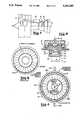
- FIG. 1is an illustration of a diagrammatic cross-sectional view of a gas turbine engine embodying the present invention.
- FIG. 2is an illustration of a diagrammatic cross-sectional view illustrating in more detail the new and improved clearance control system.
- FIG. 3is a schematic view of the prior art eccentrically ground rotor and shroud structure.
- FIG. 4is an illustration of a schematic view of the new and improved clearance control system having two separate and distinct air impingement manifolds.
- FIG. 5is an illustration of a schematic view of an alternate embodiment of a clearance control system in accordance with the present invention.
- FIG. 1Illustrated in FIG. 1 is a gas turbine engine 10 comprising a fan section 12, compressor 14, combustor 16, high pressure turbine 18 and low pressure turbine 20, all in serial, axial flow relationship and disposed coaxially about the engine centerline 22.
- the high pressure turbine 18comprises a single-stage row of rotor blades 24 disposed in the hot gas stream flowpath 26 and circumscribed by an annular shroud 28. Hot turbine gases in the hot gas stream flowpath 26 are directed against rotor blades 24 so that the inertial force of the gases causes the blades 24 to rotate.
- the rotor blade clearanceis decreased by radially expanding and contracting the shroud support ring structure 11 to match the radial expansion and contraction of rotor blades 24.
- a segmented annular shroud 28is preferably made of a number of annular sectors attached to an annular ring 30 of shroud support 11.
- Annular ring 30has at its rearward end a radially inwardly extending collar 32 which is attached to the annular shroud 28 by way of the annular segmented bracket 34.
- the forward side of the ring 30is attached to the shroud 28 by way of the annular segmented bracket 36.
- Axial support for the annular segmented bracket 36is derived by axially extending a segmented ring 38 in a rearward and radially outward direction to mate with the collar 32.
- At least one separate and distinct hot air impingement manifold 40which form an annular plenum 42.
- manifolds 40In communication with manifolds 40 is a plurality of air bleed-off conduits 44 which carry hot air from the intermediate stages of the compressor 14 (FIG. 1) to plenums 42.
- the ring 30is shown to include radially outwardly extending flanges 46 and 48 which project towards plenums 42, but not to the extent of contact with manifolds 40.
- Both ring 30 and flanges 46 and 48are composed of a material having a relatively high coefficient of thermal expansion.
- Hot bleed air in plenums 42is directed through holes 50 in manifolds 40 thereby impinging on ring 30 and flanges 46 and 48 to cause radial expansion and/or contraction.
- the amount of expansion and/or contraction of flanges 46 and 48 and ring 30can be controlled.
- the controlled radial expansion and/or contraction of flanges 46 and 48 and ring 30 during appropriate stages of engine operationpermit close matching of the radial growth or shrinkage of shroud 28 to the radial growth or shrinkage of the rotor 52 thereby maintaining an allowable clearance between them.
- two separate and distinct hot air impingement manifolds 40a and 40bare shown surrounding flanges 46 and 48 and ring 30.
- Impingement manifolds 40a and 40bare provided with upper control valve means 54a and lower control valve means 54b effective for regulating hot airflow into the manifolds 40a and 40b.
- upper control valve means 54a and lower control valve means 54beffective for regulating hot airflow into the manifolds 40a and 40b.
- large loadsdevelop that tend to cause the center of rotation of the rotor 52 to become eccentric to the engine centerline 22.
- the clearance between the blade tips 25 and the surrounding shroud 28can be regulated for various flight and load conditions. For example, as shown in FIG.
- upper air control valve means 54acan be closed while lower air control valve means 54b can be open permitting hot gas to enter the lower manifold 40b but not the upper manifold 40a.
- the uneven heatingwill result in expanding the lower portion of shroud 28 to a greater extent than the upper portion of the shroud 28, thereby producing ovalization of the shroud as shown. This ovalization results in minimizing the clearance effects of eccentric loadings by allowing the shroud to conform to high load induced nonconcentricities of the rotor.
- the inventionallows the shroud to return to a more desirable low maneuver leakage configuration during low load conditions.
- the inventionwill provide a gas turbine engine capable of operating over a variety of engine and aircraft maneuvers without attendant interference between the rotor 52 and the surrounding shroud 28.
- FIG. 5An advanced form of the present invention is shown in FIG. 5 wherein the impingement manifold 40aand 40b have been segmented into a plurality of manifold segments 40a-1, 40a-2, 40a-3, 40a-4, 40a-5, 40b-1, 40b-2, and 40b-3.
- the stator shroud 28is ground eccentrically, as shown in FIG. 3, in order to maintain nearly uniform clearances at high power conditions. At lower power conditions, the rotor and stator centers are more closely aligned resulting in a more open clearance as shown in FIG. 3.
- Uniform circumferential clearancesare restored at low power conditions by preferentially cooling the lower arc portion of flanges 46 and 48 by means of preferential cooling impingement manifold segments 40a-1, 40a-2, 40a-3, 40a-4, 40a-5, 40b-1, 40b-2, and 40b-3.
- the manifold segments 40b-1, 40b-2, and 40b-3have substantially more impingement holes than segments 40a-1, 40a-2, 40a-3, 40a-4, and 40a-5, thus providing additional cooling over the lower portion of the flanges 46 and 48.
- the additional cooling of the lower arc of flanges 46 and 48results in an ovalization of the shrouds 28 yielding more uniform clearances at low power conditions.
- a further refinement of the inventionis that a valve 60 is provided to control the airflow and more particularly divert air from the lower manifold to restrict airflow to the lower manifold segments 40b-1, 40b-2, and 40b-3 at high power conditions.
- the diversion of air from the lower manifold segmentscauses the manifolds to create a more nearly uniform circumferential temperature distribution in flanges 46 and 48, thus producing more uniform tip clearance at the high power conditions.
- This refinementis of particular value in reducing transient exhaust gas temperature during an acceleration to high power conditions.
- the valve 60preferably can be operated by either the engine control unit (ECU) or a mechanical switch governed by engine pressure ratios.
- Another feature of the present inventionis that by using additional manifolds and airflow and temperature control valve means, shroud portions which might experience blade rubs can be eliminated without increasing overall blade clearances. For example, by using a separate manifold and hot air control valve means, one can expand an individual shroud portion while easily maintaining the same blade-shroud clearance along the remaining portions of the shroud.
Landscapes
- Engineering & Computer Science (AREA)
- Mechanical Engineering (AREA)
- General Engineering & Computer Science (AREA)
- Turbine Rotor Nozzle Sealing (AREA)
Abstract
Description
The present invention is directed to improvements in gas turbine engines and, more particularly, to improved means for controlling clearance between a rotor and a surrounding shroud.
In an effort to maintain a high degree of efficiency, manufacturers of turbine engines have strived to maintain the closest possible clearance between a rotor blade tip and the surrounding stationary shroud structure, because any gas which passes therebetween represents a loss of energy to the system. If a system were to operate only under steady-state maximum power conditions, it would be a simple matter to establish the desired close clearance relationship between the rotor blades and the surrounding stationary shroud. However, in reality, all turbine engines must initially be brought from a standstill condition up to steady-stat speed and then eventually decelerate to the standstill condition.
This transitional operation is not completed with the ideal low clearance condition just described. The problems in maintaining the desired clearance between the rotor and shrouds under these transitional conditions are caused by first, the mechanical expansion and shrinkage of the rotating rotor disk and blades as brought about by changes in speed, and secondly, by the relative thermal growth between the rotating rotor and surrounding stationary shroud support structure caused by differences in thermal expansion between the two structures. One commonly used method of decreasing the tip clearance between the rotor blades and the surrounding shroud has been to direct and modulate variable temperature air or variable cooling airflow rates along the entire outer circumference of the stationary shroud support structure. In this method, the air is directed on the turbine section during appropriate stages of engine operation to change the radial growth or shrinkage rate of the entire turbine shroud support in an effort to match the growth or shrinkage of the rotating turbine parts.
However, additional problems occur during an aircraft maneuver, such as during takeoff and landing. During these maneuvers, engine loadings develop that become eccentric to the engine centerline. One common method of minimizing the clearance effects of eccentric loadings is to eccentrically grind the stationary surrounding shroud, as is shown in FIG. 3. However, this method results in additional airflow leakage around the rotor blades during steady-state, low maneuver load conditions as a result of the added clearance between the rotor blades and a portion of the surrounding shroud.
It is an object of the present invention to provide an improved gas turbine engine which is capable of transitioning between various aircraft flight conditions while maintaining an allowable clearance between its rotor and the surrounding shroud.
Another object of this invention is to provide a gas turbine engine capable of operating over a variety of engine and aircraft maneuvers without attendant interference between the rotor and any portion of the surrounding stationary shroud.
Still another object of this invention is to provide a system for use in a gas turbine engine capable of continually regulating the clearance between rotor blades and circumferential sections of the surrounding shroud.
According to one form of the present invention, a new and approved clearance control system comprising a rotor, a shroud and a means to expand or contract individual portions of the shroud. In a preferred embodiment of the invention, the means varies the shape of the shroud to conform to build-up and high load induced nonconcentricities of the rotor.
These and other objects of the invention, together with the features and advantages thereof, will become apparent from the following detailed specification when read in conjunction with the accompanying drawings in which applicable reference numerals have been carried forward.
The invention, together with further objects and advantages thereof, is more particularly described in the following detailed description taken in conjunction with the accompanying drawings in which:
FIG. 1 is an illustration of a diagrammatic cross-sectional view of a gas turbine engine embodying the present invention.
FIG. 2 is an illustration of a diagrammatic cross-sectional view illustrating in more detail the new and improved clearance control system.
FIG. 3 is a schematic view of the prior art eccentrically ground rotor and shroud structure.
FIG. 4 is an illustration of a schematic view of the new and improved clearance control system having two separate and distinct air impingement manifolds.
FIG. 5 is an illustration of a schematic view of an alternate embodiment of a clearance control system in accordance with the present invention.
Illustrated in FIG. 1 is agas turbine engine 10 comprising afan section 12,compressor 14,combustor 16,high pressure turbine 18 andlow pressure turbine 20, all in serial, axial flow relationship and disposed coaxially about theengine centerline 22.
Referring now to FIG. 2, thehigh pressure turbine 18 and associated structures are shown in greater detail with the present invention incorporated therein. Thehigh pressure turbine 18 comprises a single-stage row ofrotor blades 24 disposed in the hotgas stream flowpath 26 and circumscribed by anannular shroud 28. Hot turbine gases in the hotgas stream flowpath 26 are directed againstrotor blades 24 so that the inertial force of the gases causes theblades 24 to rotate.
The efficiency of this transfer of inertial force is a major factor in the overall efficiency of the engine. One means of improving the efficiency of this transfer is to decrease any leakage of hot gases between the tips of theblades 24 and the annularstationary shroud 28.
In the embodiment of the invention shown in FIG. 2, the rotor blade clearance is decreased by radially expanding and contracting the shroud support ring structure 11 to match the radial expansion and contraction ofrotor blades 24.
A segmentedannular shroud 28 is preferably made of a number of annular sectors attached to anannular ring 30 of shroud support 11.Annular ring 30 has at its rearward end a radially inwardly extendingcollar 32 which is attached to theannular shroud 28 by way of the annular segmentedbracket 34. The forward side of thering 30 is attached to theshroud 28 by way of the annular segmentedbracket 36. Axial support for the annular segmentedbracket 36 is derived by axially extending a segmentedring 38 in a rearward and radially outward direction to mate with thecollar 32.
Located radially outwardly from theannular ring 30 is at least one separate and distinct hot air impingement manifold 40 which form anannular plenum 42. In communication with manifolds 40 is a plurality of air bleed-offconduits 44 which carry hot air from the intermediate stages of the compressor 14 (FIG. 1) to plenums 42.
Referring now more specifically to theannular ring 30, thering 30 is shown to include radially outwardly extendingflanges plenums 42, but not to the extent of contact with manifolds 40. Bothring 30 andflanges plenums 42 is directed through holes 50 in manifolds 40 thereby impinging onring 30 andflanges air entering plenums 42, the amount of expansion and/or contraction offlanges ring 30 can be controlled. The controlled radial expansion and/or contraction offlanges ring 30 during appropriate stages of engine operation permit close matching of the radial growth or shrinkage ofshroud 28 to the radial growth or shrinkage of therotor 52 thereby maintaining an allowable clearance between them.
In a preferred embodiment of the invention, as illustrated in FIG. 4, two separate and distinct hotair impingement manifolds flanges ring 30.Impingement manifolds manifolds rotor 52 to become eccentric to theengine centerline 22. By controlling the amount of hot air and by directing it into a selected manifold or manifolds, the clearance between theblade tips 25 and the surroundingshroud 28 can be regulated for various flight and load conditions. For example, as shown in FIG. 4, upper air control valve means 54a can be closed while lower air control valve means 54b can be open permitting hot gas to enter thelower manifold 40b but not theupper manifold 40a. This results in hot air impinging and heating the lower part ofring 30 andflanges 46 and 48 (FIG. 2), while the upper part of the ring and flanges would remain relatively cool. The uneven heating will result in expanding the lower portion ofshroud 28 to a greater extent than the upper portion of theshroud 28, thereby producing ovalization of the shroud as shown. This ovalization results in minimizing the clearance effects of eccentric loadings by allowing the shroud to conform to high load induced nonconcentricities of the rotor. However, unlike the prior art method of shroud grinding, the invention allows the shroud to return to a more desirable low maneuver leakage configuration during low load conditions. In this way, the invention will provide a gas turbine engine capable of operating over a variety of engine and aircraft maneuvers without attendant interference between therotor 52 and the surroundingshroud 28.
An advanced form of the present invention is shown in FIG. 5 wherein theimpingement manifold 40aand 40b have been segmented into a plurality ofmanifold segments 40a-1, 40a-2, 40a-3, 40a-4, 40a-5, 40b-1, 40b-2, and 40b-3. In this embodiment, thestator shroud 28 is ground eccentrically, as shown in FIG. 3, in order to maintain nearly uniform clearances at high power conditions. At lower power conditions, the rotor and stator centers are more closely aligned resulting in a more open clearance as shown in FIG. 3. Uniform circumferential clearances are restored at low power conditions by preferentially cooling the lower arc portion offlanges impingement manifold segments 40a-1, 40a-2, 40a-3, 40a-4, 40a-5, 40b-1, 40b-2, and 40b-3. In particular, themanifold segments 40b-1, 40b-2, and 40b-3, have substantially more impingement holes thansegments 40a-1, 40a-2, 40a-3, 40a-4, and 40a-5, thus providing additional cooling over the lower portion of theflanges flanges shrouds 28 yielding more uniform clearances at low power conditions.
A further refinement of the invention is that avalve 60 is provided to control the airflow and more particularly divert air from the lower manifold to restrict airflow to thelower manifold segments 40b-1, 40b-2, and 40b-3 at high power conditions. The diversion of air from the lower manifold segments causes the manifolds to create a more nearly uniform circumferential temperature distribution inflanges valve 60 preferably can be operated by either the engine control unit (ECU) or a mechanical switch governed by engine pressure ratios.
Another feature of the present invention is that by using additional manifolds and airflow and temperature control valve means, shroud portions which might experience blade rubs can be eliminated without increasing overall blade clearances. For example, by using a separate manifold and hot air control valve means, one can expand an individual shroud portion while easily maintaining the same blade-shroud clearance along the remaining portions of the shroud.
It will be clear to those skilled in the art that the present invention is not limited to the specific embodiments described and illustrated herein. Rather, it applies equally to any gas turbine engine clearance control system which uses heating and cooling to expand or contract shrouded surfaces. As an example, an electrical zone heating system could also be used.
It will be understood that the dimensions and proportional and structural relationships shown in the drawings are by way of example only, and these illustrations are not to be taken as the actual dimensions or proportional structural relationships used in the clearance control system of the present invention.
Numerous modifications, variations, and full and partial equivalents can now be undertaken without departing from the invention as limited only by the spirit and scope of the appended claims.
Claims (9)
1. In a gas turbine engine, a clearance control system comprising:
a) a rotor;
b) an annular shroud surrounding said rotor;
c) a shroud support structure attached to said shroud;
d) means for generating a non-uniform circumferential temperature distribution in the shroud support structure to produce ovalization of said shroud during selected operating conditions of aid gas turbine engine, wherein said generating means further comprises:
i) an upper circumferentially extending air impingement manifold surrounding an upper portion of said shroud support structure for impinging compressed air on said upper portion of said shroud support structure;
ii) a lower circumferentially extending air impingement manifold surrounding a lower portion of said shroud support structure for impinging compressed air on said lower portion of said shroud support structure, said lower manifold being separate from said upper manifold;
iii) an upper control valve for controlling a temperature and a flow rate of a first airflow supplied to said upper manifold; and
iv) a lower control valve for controlling a temperature and a flow rate of a second airflow supplied to said lower manifold, wherein said upper control valve and said lower control valve are separately controlled.
2. In a gas turbine engine, a clearance control system comprising:
a) a rotor having a plurality of blades and a center of rotation about an engine centerline;
b) a shroud radially surrounding said blades and concentric with said rotor;
c) a shroud support structure attached to said shroud;
d) means for varying a circumferential temperature distribution of said shroud support structure to conform to high load induced nonconcentricities of said rotor, wherein said varying means further comprises:
i) an upper circumferentially extending air impingement manifold surrounding an upper portion of said shroud support structure for impinging compressed air on said upper portion of said shroud support structure;
ii) a lower circumferentially extending air impingement manifold surrounding a lower portion of said shroud support structure for impinging compressed air on said lower portion of said shroud support structure, said lower manifold being separate from said upper manifold;
iii) an upper control valve for controlling a temperature and a flow rate of a first airflow supplied to said upper manifold; and
iv) a lower control valve for controlling a temperature and a flow rate of a second airflow supplied to said lower manifold, wherein said upper control valve and said lower control valve are separately controlled.
3. A clearance control system according to claim 2, wherein:
a) the shroud support structure includes an annular ring having a plurality of flanges; and
b) each of said impingement manifolds surrounds said flanges.
4. A clearance control system according to claim 3, wherein said annular ring and said flanges are composed of a material having a relatively high coefficient of thermal expansion.
5. A clearance control system according to claim 3, wherein air impinges on said ring and on said flanges to regulate an annular clearance between said shroud and said blades.
6. A clearance control system according to claim 5, wherein said plurality of flanges includes a forward flange and an aft flange, wherein each of said flanges extends in a radially outward direction.
7. In a gas turbine engine, a clearance control system comprising:
a) a rotor including a plurality of blades, each of said blades having a radially outward tip;
b) an annular shroud surrounding said rotor, wherein a radially inward and radially facing surface of said shroud is eccentrically ground to conform to nonconcentricities of aid rotor during high power conditions of said gas turbine engine;
c) a shroud support structure attached to said shroud;
d) means for preferentially cooling a lower portion of said shroud support structure during low power conditions of said gas turbine engine to enhance uniformity of an annular clearance between said shroud radially inward surface and said blade tips, said cooling means comprising a plurality of circumferentially extending lower air manifolds for impinging air on a lower portion of said shroud support structure; and
e) means for diverting air from said plurality of lower air manifolds during said high power conditions of said gas turbine engine to enhance uniformity of said annular clearance and to reduce a transient exhaust gas temperature of said gas turbine engine during an acceleration of said gas turbine engine to said high power conditions.
8. A clearance control system according to claim 7, further comprising a plurality of circumferentially extending upper air manifolds for impinging air on an upper portion of said shroud support structure, wherein said lower air manifolds include a plurality of impingement holes which are substantially greater than a plurality of impingement hole in said upper air manifolds.
9. A clearance control system according to claim 8, wherein said diverting means comprises a valve.
Priority Applications (4)
| Application Number | Priority Date | Filing Date | Title |
|---|---|---|---|
| US07/631,512US5281085A (en) | 1990-12-21 | 1990-12-21 | Clearance control system for separately expanding or contracting individual portions of an annular shroud |
| CA002056591ACA2056591A1 (en) | 1990-12-21 | 1991-11-28 | Clearance control system |
| EP91311380AEP0492865A1 (en) | 1990-12-21 | 1991-12-06 | Clearance control system |
| JP3350498AJPH04301102A (en) | 1990-12-21 | 1991-12-11 | Clearance controller for gas turbine engine |
Applications Claiming Priority (1)
| Application Number | Priority Date | Filing Date | Title |
|---|---|---|---|
| US07/631,512US5281085A (en) | 1990-12-21 | 1990-12-21 | Clearance control system for separately expanding or contracting individual portions of an annular shroud |
Publications (1)
| Publication Number | Publication Date |
|---|---|
| US5281085Atrue US5281085A (en) | 1994-01-25 |
Family
ID=24531528
Family Applications (1)
| Application Number | Title | Priority Date | Filing Date |
|---|---|---|---|
| US07/631,512Expired - LifetimeUS5281085A (en) | 1990-12-21 | 1990-12-21 | Clearance control system for separately expanding or contracting individual portions of an annular shroud |
Country Status (4)
| Country | Link |
|---|---|
| US (1) | US5281085A (en) |
| EP (1) | EP0492865A1 (en) |
| JP (1) | JPH04301102A (en) |
| CA (1) | CA2056591A1 (en) |
Cited By (66)
| Publication number | Priority date | Publication date | Assignee | Title |
|---|---|---|---|---|
| US5399066A (en)* | 1993-09-30 | 1995-03-21 | General Electric Company | Integral clearance control impingement manifold and environmental shield |
| US5540547A (en)* | 1994-06-23 | 1996-07-30 | General Electric Company | Method and apparatus for damping vibrations of external tubing of a gas turbine engine |
| US5667358A (en)* | 1995-11-30 | 1997-09-16 | Westinghouse Electric Corporation | Method for reducing steady state rotor blade tip clearance in a land-based gas turbine to improve efficiency |
| US5685693A (en)* | 1995-03-31 | 1997-11-11 | General Electric Co. | Removable inner turbine shell with bucket tip clearance control |
| US6035929A (en)* | 1997-07-18 | 2000-03-14 | Societe Nationale D'etude Et De Construction De Moteurs D'aviation "Snecma" | Apparatus for heating or cooling a circular housing |
| US6190127B1 (en)* | 1998-12-22 | 2001-02-20 | General Electric Co. | Tuning thermal mismatch between turbine rotor parts with a thermal medium |
| US6379108B1 (en) | 2000-08-08 | 2002-04-30 | General Electric Company | Controlling a rabbet load and air/oil seal temperatures in a turbine |
| US6382905B1 (en) | 2000-04-28 | 2002-05-07 | General Electric Company | Fan casing liner support |
| US6409471B1 (en)* | 2001-02-16 | 2002-06-25 | General Electric Company | Shroud assembly and method of machining same |
| US6454529B1 (en) | 2001-03-23 | 2002-09-24 | General Electric Company | Methods and apparatus for maintaining rotor assembly tip clearances |
| US6659716B1 (en)* | 2002-07-15 | 2003-12-09 | Mitsubishi Heavy Industries, Ltd. | Gas turbine having thermally insulating rings |
| US20040090273A1 (en)* | 2002-11-08 | 2004-05-13 | Chia-Yang Chang | Digital adjustable chip oscillator |
| US20050000227A1 (en)* | 2003-07-02 | 2005-01-06 | Mccaffrey Timothy P. | Methods and apparatus for operating gas turbine engine combustors |
| US20050000226A1 (en)* | 2003-07-02 | 2005-01-06 | Mccaffrey Timothy P. | Methods and apparatus for operating gas turbine engine combustors |
| US20050042080A1 (en)* | 2003-08-06 | 2005-02-24 | Snecma Moteurs | Device for controlling clearance in a gas turbine |
| US20050081528A1 (en)* | 2003-10-17 | 2005-04-21 | Howell Stephen J. | Methods and apparatus for attaching swirlers to turbine engine combustors |
| US20050081527A1 (en)* | 2003-10-17 | 2005-04-21 | Howell Stephen J. | Methods and apparatus for film cooling gas turbine engine combustors |
| US20050081526A1 (en)* | 2003-10-17 | 2005-04-21 | Howell Stephen J. | Methods and apparatus for cooling turbine engine combustor exit temperatures |
| US6886343B2 (en) | 2003-01-15 | 2005-05-03 | General Electric Company | Methods and apparatus for controlling engine clearance closures |
| US20050109016A1 (en)* | 2003-11-21 | 2005-05-26 | Richard Ullyott | Turbine tip clearance control system |
| US20050126181A1 (en)* | 2003-04-30 | 2005-06-16 | Pratt & Whitney Canada Corp. | Hybrid turbine tip clearance control system |
| US20050238477A1 (en)* | 2004-03-18 | 2005-10-27 | Snecma Moteurs | Stator of a high-pressure turbine of a turbomachine, and a method of assembling it |
| US20060042266A1 (en)* | 2004-08-25 | 2006-03-02 | Albers Robert J | Methods and apparatus for maintaining rotor assembly tip clearances |
| US7040096B2 (en) | 2003-09-08 | 2006-05-09 | General Electric Company | Methods and apparatus for supplying feed air to turbine combustors |
| RU2276733C2 (en)* | 2000-11-09 | 2006-05-20 | Снекма Мотёр | Stator ring ventilating unit |
| US20070140839A1 (en)* | 2005-12-16 | 2007-06-21 | Bucaro Michael T | Thermal control of gas turbine engine rings for active clearance control |
| US20080089780A1 (en)* | 2006-10-12 | 2008-04-17 | General Electric Company | Turbine case impingement cooling for heavy duty gas turbines |
| US20080112798A1 (en)* | 2006-11-15 | 2008-05-15 | General Electric Company | Compound clearance control engine |
| US20080112797A1 (en)* | 2006-11-15 | 2008-05-15 | General Electric Company | Transpiration clearance control turbine |
| US20090053035A1 (en)* | 2007-08-23 | 2009-02-26 | General Electric Company | Apparatus and method for reducing eccentricity and out-of-roundness in turbines |
| US7503179B2 (en) | 2005-12-16 | 2009-03-17 | General Electric Company | System and method to exhaust spent cooling air of gas turbine engine active clearance control |
| US20100034635A1 (en)* | 2006-10-12 | 2010-02-11 | General Electric Company | Predictive Model Based Control System for Heavy Duty Gas Turbines |
| US20100054911A1 (en)* | 2008-08-29 | 2010-03-04 | General Electric Company | System and method for adjusting clearance in a gas turbine |
| US20100111679A1 (en)* | 2008-10-30 | 2010-05-06 | General Electric Company | Asymmetrical gas turbine cooling port locations |
| US20100118914A1 (en)* | 2008-11-10 | 2010-05-13 | General Electric Company | Externally adjustable impingement cooling manifold mount and thermocouple housing |
| US20100313404A1 (en)* | 2009-06-12 | 2010-12-16 | Rolls-Royce Plc | System and method for adjusting rotor-stator clearance |
| US20110179805A1 (en)* | 2010-01-28 | 2011-07-28 | Bruno Chatelois | Rotor containment structure for gas turbine engine |
| US20120167584A1 (en)* | 2009-09-08 | 2012-07-05 | Snecma | Controlling blade tip clearances in a turbine engine |
| EP2551467A1 (en)* | 2011-07-26 | 2013-01-30 | United Technologies Corporation | Gas turbine engine active clearance control system and corresponding method |
| US20130084162A1 (en)* | 2011-09-29 | 2013-04-04 | Hitachi, Ltd. | Gas Turbine |
| US20130330167A1 (en)* | 2012-06-08 | 2013-12-12 | Philip Robert Rioux | Active clearance control for gas turbine engine |
| US20140230400A1 (en)* | 2013-02-15 | 2014-08-21 | Kevin M. Light | Heat retention and distribution system for gas turbine engines |
| US20140248115A1 (en)* | 2012-12-19 | 2014-09-04 | United Technologies Corporation | Active Clearance Control System with Zone Controls |
| US20140271104A1 (en)* | 2013-03-13 | 2014-09-18 | General Electric Company | Turbine Shroud Cooling System |
| US20140271154A1 (en)* | 2013-03-14 | 2014-09-18 | General Electric Company | Casing for turbine engine having a cooling unit |
| US20140301834A1 (en)* | 2013-04-03 | 2014-10-09 | Barton M. Pepperman | Turbine cylinder cavity heated recirculation system |
| US8920109B2 (en) | 2013-03-12 | 2014-12-30 | Siemens Aktiengesellschaft | Vane carrier thermal management arrangement and method for clearance control |
| WO2015038906A1 (en)* | 2013-09-12 | 2015-03-19 | United Technologies Corporation | Blade tip clearance control system including boas support |
| US9039346B2 (en) | 2011-10-17 | 2015-05-26 | General Electric Company | Rotor support thermal control system |
| US20150247417A1 (en)* | 2013-08-29 | 2015-09-03 | Rolls-Royce Plc | Rotor tip clearance |
| US9238971B2 (en) | 2012-10-18 | 2016-01-19 | General Electric Company | Gas turbine casing thermal control device |
| US9266618B2 (en) | 2013-11-18 | 2016-02-23 | Honeywell International Inc. | Gas turbine engine turbine blade tip active clearance control system and method |
| US9341074B2 (en) | 2012-07-25 | 2016-05-17 | General Electric Company | Active clearance control manifold system |
| US9422824B2 (en) | 2012-10-18 | 2016-08-23 | General Electric Company | Gas turbine thermal control and related method |
| US20160348587A1 (en)* | 2014-02-04 | 2016-12-01 | United Technologies Corporation | Brackets for gas turbine engine components |
| US20170254225A1 (en)* | 2016-03-07 | 2017-09-07 | Mitsubishi Hitachi Power Systems, Ltd. | Steam Turbine Plant |
| US20180030987A1 (en)* | 2016-08-01 | 2018-02-01 | General Electric Company | Method and apparatus for active clearance control on gas turbine engines |
| US20180320541A1 (en)* | 2017-05-08 | 2018-11-08 | United Technologies Corporation | Re-Use and Modulated Cooling from Tip Clearance Control System for Gas Turbine Engine |
| US10132187B2 (en) | 2013-08-07 | 2018-11-20 | United Technologies Corporation | Clearance control assembly |
| US10294818B2 (en)* | 2014-08-21 | 2019-05-21 | Siemens Aktiengesellschaft | Gas turbine having an annular passage subdivided into annulus sectors |
| US10329941B2 (en)* | 2016-05-06 | 2019-06-25 | United Technologies Corporation | Impingement manifold |
| US10393149B2 (en) | 2016-03-11 | 2019-08-27 | General Electric Company | Method and apparatus for active clearance control |
| US10612409B2 (en) | 2016-08-18 | 2020-04-07 | United Technologies Corporation | Active clearance control collector to manifold insert |
| US20200165933A1 (en)* | 2017-06-13 | 2020-05-28 | Rolls-Royce Corporation | Tip clearance control system |
| US20230146084A1 (en)* | 2021-11-05 | 2023-05-11 | General Electric Company | Gas turbine engine with clearance control system |
| US12305516B2 (en) | 2021-11-05 | 2025-05-20 | General Electric Company | Gas turbine engine with a fluid conduit system and a method of operating the same |
Families Citing this family (14)
| Publication number | Priority date | Publication date | Assignee | Title |
|---|---|---|---|---|
| US5212940A (en)* | 1991-04-16 | 1993-05-25 | General Electric Company | Tip clearance control apparatus and method |
| FR2766232B1 (en)* | 1997-07-18 | 1999-08-20 | Snecma | CIRCULAR HOUSING COOLING OR HEATING DEVICE |
| DE10032454A1 (en)* | 2000-07-04 | 2002-01-17 | Man Turbomasch Ag Ghh Borsig | Device for cooling an unevenly highly temperature-stressed component |
| FR2867806B1 (en)* | 2004-03-18 | 2006-06-02 | Snecma Moteurs | DEVICE FOR CONTROLLING GAS TURBINE SET WITH AIR FLOW BALANCING |
| WO2006108454A1 (en)* | 2005-04-11 | 2006-10-19 | Alstom Technology Ltd | Guide vane support |
| US7491029B2 (en) | 2005-10-14 | 2009-02-17 | United Technologies Corporation | Active clearance control system for gas turbine engines |
| US7771160B2 (en) | 2006-08-10 | 2010-08-10 | United Technologies Corporation | Ceramic shroud assembly |
| US7665960B2 (en) | 2006-08-10 | 2010-02-23 | United Technologies Corporation | Turbine shroud thermal distortion control |
| US8177501B2 (en)* | 2009-01-08 | 2012-05-15 | General Electric Company | Stator casing having improved running clearances under thermal load |
| US8342798B2 (en)* | 2009-07-28 | 2013-01-01 | General Electric Company | System and method for clearance control in a rotary machine |
| US8167546B2 (en) | 2009-09-01 | 2012-05-01 | United Technologies Corporation | Ceramic turbine shroud support |
| EP2754859A1 (en)* | 2013-01-10 | 2014-07-16 | Alstom Technology Ltd | Turbomachine with active electrical clearance control and corresponding method |
| WO2014163673A2 (en) | 2013-03-11 | 2014-10-09 | Bronwyn Power | Gas turbine engine flow path geometry |
| US10513944B2 (en)* | 2015-12-21 | 2019-12-24 | General Electric Company | Manifold for use in a clearance control system and method of manufacturing |
Citations (24)
| Publication number | Priority date | Publication date | Assignee | Title |
|---|---|---|---|---|
| US1678065A (en)* | 1925-06-17 | 1928-07-24 | Westinghouse Electric & Mfg Co | Turbine |
| US1678066A (en)* | 1925-11-04 | 1928-07-24 | Westinghouse Electric & Mfg Co | Turbine-cooling means |
| US1734216A (en)* | 1927-04-19 | 1929-11-05 | Westinghouse Electric & Mfg Co | Elastic-fluid turbine |
| FR718703A (en)* | 1930-07-08 | 1932-01-28 | Const Mecaniques Escher Sa Des | Steam or gas turbine, especially for high temperature and pressure |
| US2402841A (en)* | 1944-06-26 | 1946-06-25 | Allis Chalmers Mfg Co | Elastic fluid turbine apparatus |
| US3029064A (en)* | 1958-07-11 | 1962-04-10 | Napier & Son Ltd | Temperature control apparatus for turbine cases |
| GB1248198A (en)* | 1970-02-06 | 1971-09-29 | Rolls Royce | Sealing device |
| US4023731A (en)* | 1974-12-19 | 1977-05-17 | General Electric Company | Thermal actuated valve for clearance control |
| US4069662A (en)* | 1975-12-05 | 1978-01-24 | United Technologies Corporation | Clearance control for gas turbine engine |
| JPS5554672A (en)* | 1978-10-16 | 1980-04-22 | Hitachi Ltd | Hydraulic machine runner touching accident preventing system |
| US4213296A (en)* | 1977-12-21 | 1980-07-22 | United Technologies Corporation | Seal clearance control system for a gas turbine |
| US4268221A (en)* | 1979-03-28 | 1981-05-19 | United Technologies Corporation | Compressor structure adapted for active clearance control |
| US4305697A (en)* | 1980-03-19 | 1981-12-15 | General Electric Company | Method and replacement member for repairing a gas turbine engine vane assembly |
| US4329114A (en)* | 1979-07-25 | 1982-05-11 | The United States Of America As Represented By The Administrator Of The National Aeronautics And Space Administration | Active clearance control system for a turbomachine |
| US4332133A (en)* | 1979-11-14 | 1982-06-01 | United Technologies Corporation | Compressor bleed system for cooling and clearance control |
| US4363599A (en)* | 1979-10-31 | 1982-12-14 | General Electric Company | Clearance control |
| US4388124A (en)* | 1979-04-27 | 1983-06-14 | General Electric Company | Cyclic oxidation-hot corrosion resistant nickel-base superalloys |
| GB2117842A (en)* | 1982-03-25 | 1983-10-19 | Rolls Royce | Means for equalising the temperatures within a gas turbine engine |
| US4522559A (en)* | 1982-02-19 | 1985-06-11 | General Electric Company | Compressor casing |
| US4553901A (en)* | 1983-12-21 | 1985-11-19 | United Technologies Corporation | Stator structure for a gas turbine engine |
| EP0188724A1 (en)* | 1984-12-24 | 1986-07-30 | Allied Corporation | Turbine blade clearance controller |
| US4826397A (en)* | 1988-06-29 | 1989-05-02 | United Technologies Corporation | Stator assembly for a gas turbine engine |
| EP0423025A1 (en)* | 1989-10-11 | 1991-04-17 | Societe Nationale D'etude Et De Construction De Moteurs D'aviation "Snecma" | Adjustment of eccentric radial clearances in turbomachines |
| US5100291A (en)* | 1990-03-28 | 1992-03-31 | General Electric Company | Impingement manifold |
Family Cites Families (1)
| Publication number | Priority date | Publication date | Assignee | Title |
|---|---|---|---|---|
| JPS63154806A (en)* | 1986-12-19 | 1988-06-28 | Mitsubishi Heavy Ind Ltd | Blade tip clearance adjuster for rotary machine |
- 1990
- 1990-12-21USUS07/631,512patent/US5281085A/ennot_activeExpired - Lifetime
- 1991
- 1991-11-28CACA002056591Apatent/CA2056591A1/ennot_activeAbandoned
- 1991-12-06EPEP91311380Apatent/EP0492865A1/ennot_activeWithdrawn
- 1991-12-11JPJP3350498Apatent/JPH04301102A/enactivePending
Patent Citations (24)
| Publication number | Priority date | Publication date | Assignee | Title |
|---|---|---|---|---|
| US1678065A (en)* | 1925-06-17 | 1928-07-24 | Westinghouse Electric & Mfg Co | Turbine |
| US1678066A (en)* | 1925-11-04 | 1928-07-24 | Westinghouse Electric & Mfg Co | Turbine-cooling means |
| US1734216A (en)* | 1927-04-19 | 1929-11-05 | Westinghouse Electric & Mfg Co | Elastic-fluid turbine |
| FR718703A (en)* | 1930-07-08 | 1932-01-28 | Const Mecaniques Escher Sa Des | Steam or gas turbine, especially for high temperature and pressure |
| US2402841A (en)* | 1944-06-26 | 1946-06-25 | Allis Chalmers Mfg Co | Elastic fluid turbine apparatus |
| US3029064A (en)* | 1958-07-11 | 1962-04-10 | Napier & Son Ltd | Temperature control apparatus for turbine cases |
| GB1248198A (en)* | 1970-02-06 | 1971-09-29 | Rolls Royce | Sealing device |
| US4023731A (en)* | 1974-12-19 | 1977-05-17 | General Electric Company | Thermal actuated valve for clearance control |
| US4069662A (en)* | 1975-12-05 | 1978-01-24 | United Technologies Corporation | Clearance control for gas turbine engine |
| US4213296A (en)* | 1977-12-21 | 1980-07-22 | United Technologies Corporation | Seal clearance control system for a gas turbine |
| JPS5554672A (en)* | 1978-10-16 | 1980-04-22 | Hitachi Ltd | Hydraulic machine runner touching accident preventing system |
| US4268221A (en)* | 1979-03-28 | 1981-05-19 | United Technologies Corporation | Compressor structure adapted for active clearance control |
| US4388124A (en)* | 1979-04-27 | 1983-06-14 | General Electric Company | Cyclic oxidation-hot corrosion resistant nickel-base superalloys |
| US4329114A (en)* | 1979-07-25 | 1982-05-11 | The United States Of America As Represented By The Administrator Of The National Aeronautics And Space Administration | Active clearance control system for a turbomachine |
| US4363599A (en)* | 1979-10-31 | 1982-12-14 | General Electric Company | Clearance control |
| US4332133A (en)* | 1979-11-14 | 1982-06-01 | United Technologies Corporation | Compressor bleed system for cooling and clearance control |
| US4305697A (en)* | 1980-03-19 | 1981-12-15 | General Electric Company | Method and replacement member for repairing a gas turbine engine vane assembly |
| US4522559A (en)* | 1982-02-19 | 1985-06-11 | General Electric Company | Compressor casing |
| GB2117842A (en)* | 1982-03-25 | 1983-10-19 | Rolls Royce | Means for equalising the temperatures within a gas turbine engine |
| US4553901A (en)* | 1983-12-21 | 1985-11-19 | United Technologies Corporation | Stator structure for a gas turbine engine |
| EP0188724A1 (en)* | 1984-12-24 | 1986-07-30 | Allied Corporation | Turbine blade clearance controller |
| US4826397A (en)* | 1988-06-29 | 1989-05-02 | United Technologies Corporation | Stator assembly for a gas turbine engine |
| EP0423025A1 (en)* | 1989-10-11 | 1991-04-17 | Societe Nationale D'etude Et De Construction De Moteurs D'aviation "Snecma" | Adjustment of eccentric radial clearances in turbomachines |
| US5100291A (en)* | 1990-03-28 | 1992-03-31 | General Electric Company | Impingement manifold |
Cited By (107)
| Publication number | Priority date | Publication date | Assignee | Title |
|---|---|---|---|---|
| US5399066A (en)* | 1993-09-30 | 1995-03-21 | General Electric Company | Integral clearance control impingement manifold and environmental shield |
| US5540547A (en)* | 1994-06-23 | 1996-07-30 | General Electric Company | Method and apparatus for damping vibrations of external tubing of a gas turbine engine |
| US5685693A (en)* | 1995-03-31 | 1997-11-11 | General Electric Co. | Removable inner turbine shell with bucket tip clearance control |
| US5779442A (en)* | 1995-03-31 | 1998-07-14 | General Electric Company | Removable inner turbine shell with bucket tip clearance control |
| US5906473A (en)* | 1995-03-31 | 1999-05-25 | General Electric Co. | Removable inner turbine shell with bucket tip clearance control |
| US5913658A (en)* | 1995-03-31 | 1999-06-22 | General Electric Co. | Removable inner turbine shell with bucket tip clearance control |
| US6079943A (en)* | 1995-03-31 | 2000-06-27 | General Electric Co. | Removable inner turbine shell and bucket tip clearance control |
| US6082963A (en)* | 1995-03-31 | 2000-07-04 | General Electric Co. | Removable inner turbine shell with bucket tip clearance control |
| US5667358A (en)* | 1995-11-30 | 1997-09-16 | Westinghouse Electric Corporation | Method for reducing steady state rotor blade tip clearance in a land-based gas turbine to improve efficiency |
| US6035929A (en)* | 1997-07-18 | 2000-03-14 | Societe Nationale D'etude Et De Construction De Moteurs D'aviation "Snecma" | Apparatus for heating or cooling a circular housing |
| US6190127B1 (en)* | 1998-12-22 | 2001-02-20 | General Electric Co. | Tuning thermal mismatch between turbine rotor parts with a thermal medium |
| US6382905B1 (en) | 2000-04-28 | 2002-05-07 | General Electric Company | Fan casing liner support |
| US6379108B1 (en) | 2000-08-08 | 2002-04-30 | General Electric Company | Controlling a rabbet load and air/oil seal temperatures in a turbine |
| RU2276733C2 (en)* | 2000-11-09 | 2006-05-20 | Снекма Мотёр | Stator ring ventilating unit |
| US6409471B1 (en)* | 2001-02-16 | 2002-06-25 | General Electric Company | Shroud assembly and method of machining same |
| US6454529B1 (en) | 2001-03-23 | 2002-09-24 | General Electric Company | Methods and apparatus for maintaining rotor assembly tip clearances |
| US6659716B1 (en)* | 2002-07-15 | 2003-12-09 | Mitsubishi Heavy Industries, Ltd. | Gas turbine having thermally insulating rings |
| US20040090273A1 (en)* | 2002-11-08 | 2004-05-13 | Chia-Yang Chang | Digital adjustable chip oscillator |
| US6886343B2 (en) | 2003-01-15 | 2005-05-03 | General Electric Company | Methods and apparatus for controlling engine clearance closures |
| US6925814B2 (en) | 2003-04-30 | 2005-08-09 | Pratt & Whitney Canada Corp. | Hybrid turbine tip clearance control system |
| US20050126181A1 (en)* | 2003-04-30 | 2005-06-16 | Pratt & Whitney Canada Corp. | Hybrid turbine tip clearance control system |
| US20050000226A1 (en)* | 2003-07-02 | 2005-01-06 | Mccaffrey Timothy P. | Methods and apparatus for operating gas turbine engine combustors |
| US7093419B2 (en) | 2003-07-02 | 2006-08-22 | General Electric Company | Methods and apparatus for operating gas turbine engine combustors |
| US20050000227A1 (en)* | 2003-07-02 | 2005-01-06 | Mccaffrey Timothy P. | Methods and apparatus for operating gas turbine engine combustors |
| US6955038B2 (en) | 2003-07-02 | 2005-10-18 | General Electric Company | Methods and apparatus for operating gas turbine engine combustors |
| US7114914B2 (en)* | 2003-08-06 | 2006-10-03 | Snecma Moteurs | Device for controlling clearance in a gas turbine |
| US20050042080A1 (en)* | 2003-08-06 | 2005-02-24 | Snecma Moteurs | Device for controlling clearance in a gas turbine |
| US7040096B2 (en) | 2003-09-08 | 2006-05-09 | General Electric Company | Methods and apparatus for supplying feed air to turbine combustors |
| US20050081528A1 (en)* | 2003-10-17 | 2005-04-21 | Howell Stephen J. | Methods and apparatus for attaching swirlers to turbine engine combustors |
| US20080209728A1 (en)* | 2003-10-17 | 2008-09-04 | Stephen John Howell | Methods and apparatus for attaching swirlers to turbine engine combustors |
| US7036316B2 (en) | 2003-10-17 | 2006-05-02 | General Electric Company | Methods and apparatus for cooling turbine engine combustor exit temperatures |
| US7310952B2 (en) | 2003-10-17 | 2007-12-25 | General Electric Company | Methods and apparatus for attaching swirlers to gas turbine engine combustors |
| US20050081526A1 (en)* | 2003-10-17 | 2005-04-21 | Howell Stephen J. | Methods and apparatus for cooling turbine engine combustor exit temperatures |
| US7051532B2 (en) | 2003-10-17 | 2006-05-30 | General Electric Company | Methods and apparatus for film cooling gas turbine engine combustors |
| US7721437B2 (en) | 2003-10-17 | 2010-05-25 | General Electric Company | Methods for assembling gas turbine engine combustors |
| US20050081527A1 (en)* | 2003-10-17 | 2005-04-21 | Howell Stephen J. | Methods and apparatus for film cooling gas turbine engine combustors |
| US20050109016A1 (en)* | 2003-11-21 | 2005-05-26 | Richard Ullyott | Turbine tip clearance control system |
| US7360987B2 (en)* | 2004-03-18 | 2008-04-22 | Snecma | Stator of a high-pressure turbine of a turbomachine, and a method of assembling it |
| US20050238477A1 (en)* | 2004-03-18 | 2005-10-27 | Snecma Moteurs | Stator of a high-pressure turbine of a turbomachine, and a method of assembling it |
| US7269955B2 (en) | 2004-08-25 | 2007-09-18 | General Electric Company | Methods and apparatus for maintaining rotor assembly tip clearances |
| US20060042266A1 (en)* | 2004-08-25 | 2006-03-02 | Albers Robert J | Methods and apparatus for maintaining rotor assembly tip clearances |
| US20070140839A1 (en)* | 2005-12-16 | 2007-06-21 | Bucaro Michael T | Thermal control of gas turbine engine rings for active clearance control |
| US7503179B2 (en) | 2005-12-16 | 2009-03-17 | General Electric Company | System and method to exhaust spent cooling air of gas turbine engine active clearance control |
| US7597537B2 (en) | 2005-12-16 | 2009-10-06 | General Electric Company | Thermal control of gas turbine engine rings for active clearance control |
| US20080089780A1 (en)* | 2006-10-12 | 2008-04-17 | General Electric Company | Turbine case impingement cooling for heavy duty gas turbines |
| US8801370B2 (en)* | 2006-10-12 | 2014-08-12 | General Electric Company | Turbine case impingement cooling for heavy duty gas turbines |
| US7837429B2 (en)* | 2006-10-12 | 2010-11-23 | General Electric Company | Predictive model based control system for heavy duty gas turbines |
| US20100034635A1 (en)* | 2006-10-12 | 2010-02-11 | General Electric Company | Predictive Model Based Control System for Heavy Duty Gas Turbines |
| US7740443B2 (en) | 2006-11-15 | 2010-06-22 | General Electric Company | Transpiration clearance control turbine |
| US7823389B2 (en) | 2006-11-15 | 2010-11-02 | General Electric Company | Compound clearance control engine |
| US20080112798A1 (en)* | 2006-11-15 | 2008-05-15 | General Electric Company | Compound clearance control engine |
| US20080112797A1 (en)* | 2006-11-15 | 2008-05-15 | General Electric Company | Transpiration clearance control turbine |
| US8152446B2 (en)* | 2007-08-23 | 2012-04-10 | General Electric Company | Apparatus and method for reducing eccentricity and out-of-roundness in turbines |
| CN101382087B (en)* | 2007-08-23 | 2014-08-06 | 通用电气公司 | Apparatus and method for reducing eccentricity and out-of-roundness in turbines |
| US20090053035A1 (en)* | 2007-08-23 | 2009-02-26 | General Electric Company | Apparatus and method for reducing eccentricity and out-of-roundness in turbines |
| US20100054911A1 (en)* | 2008-08-29 | 2010-03-04 | General Electric Company | System and method for adjusting clearance in a gas turbine |
| CN101725378B (en)* | 2008-10-30 | 2013-09-04 | 通用电气公司 | Asymmetrical gas turbine cooling port locations |
| US8047763B2 (en)* | 2008-10-30 | 2011-11-01 | General Electric Company | Asymmetrical gas turbine cooling port locations |
| US20100111679A1 (en)* | 2008-10-30 | 2010-05-06 | General Electric Company | Asymmetrical gas turbine cooling port locations |
| US20100118914A1 (en)* | 2008-11-10 | 2010-05-13 | General Electric Company | Externally adjustable impingement cooling manifold mount and thermocouple housing |
| US8123406B2 (en)* | 2008-11-10 | 2012-02-28 | General Electric Company | Externally adjustable impingement cooling manifold mount and thermocouple housing |
| US20100313404A1 (en)* | 2009-06-12 | 2010-12-16 | Rolls-Royce Plc | System and method for adjusting rotor-stator clearance |
| US8555477B2 (en)* | 2009-06-12 | 2013-10-15 | Rolls-Royce Plc | System and method for adjusting rotor-stator clearance |
| US9353641B2 (en)* | 2009-09-08 | 2016-05-31 | Snecma | Controlling blade tip clearances in a turbine engine |
| US20120167584A1 (en)* | 2009-09-08 | 2012-07-05 | Snecma | Controlling blade tip clearances in a turbine engine |
| US8662824B2 (en) | 2010-01-28 | 2014-03-04 | Pratt & Whitney Canada Corp. | Rotor containment structure for gas turbine engine |
| US20110179805A1 (en)* | 2010-01-28 | 2011-07-28 | Bruno Chatelois | Rotor containment structure for gas turbine engine |
| EP2551467A1 (en)* | 2011-07-26 | 2013-01-30 | United Technologies Corporation | Gas turbine engine active clearance control system and corresponding method |
| US20130084162A1 (en)* | 2011-09-29 | 2013-04-04 | Hitachi, Ltd. | Gas Turbine |
| US9039346B2 (en) | 2011-10-17 | 2015-05-26 | General Electric Company | Rotor support thermal control system |
| US8998563B2 (en)* | 2012-06-08 | 2015-04-07 | United Technologies Corporation | Active clearance control for gas turbine engine |
| US20130330167A1 (en)* | 2012-06-08 | 2013-12-12 | Philip Robert Rioux | Active clearance control for gas turbine engine |
| US9341074B2 (en) | 2012-07-25 | 2016-05-17 | General Electric Company | Active clearance control manifold system |
| US9238971B2 (en) | 2012-10-18 | 2016-01-19 | General Electric Company | Gas turbine casing thermal control device |
| US9422824B2 (en) | 2012-10-18 | 2016-08-23 | General Electric Company | Gas turbine thermal control and related method |
| US9752451B2 (en)* | 2012-12-19 | 2017-09-05 | United Technologies Corporation | Active clearance control system with zone controls |
| WO2014116325A3 (en)* | 2012-12-19 | 2014-09-25 | United Technologies Corporation | Active clearance control system with zone controls |
| US20140248115A1 (en)* | 2012-12-19 | 2014-09-04 | United Technologies Corporation | Active Clearance Control System with Zone Controls |
| CN104995374A (en)* | 2013-02-15 | 2015-10-21 | 西门子股份公司 | Heat retention and distribution systems for gas turbine engines |
| US20140230400A1 (en)* | 2013-02-15 | 2014-08-21 | Kevin M. Light | Heat retention and distribution system for gas turbine engines |
| US8920109B2 (en) | 2013-03-12 | 2014-12-30 | Siemens Aktiengesellschaft | Vane carrier thermal management arrangement and method for clearance control |
| US20140271104A1 (en)* | 2013-03-13 | 2014-09-18 | General Electric Company | Turbine Shroud Cooling System |
| US9458731B2 (en)* | 2013-03-13 | 2016-10-04 | General Electric Company | Turbine shroud cooling system |
| US20140271154A1 (en)* | 2013-03-14 | 2014-09-18 | General Electric Company | Casing for turbine engine having a cooling unit |
| US20140301834A1 (en)* | 2013-04-03 | 2014-10-09 | Barton M. Pepperman | Turbine cylinder cavity heated recirculation system |
| US10132187B2 (en) | 2013-08-07 | 2018-11-20 | United Technologies Corporation | Clearance control assembly |
| US9657587B2 (en)* | 2013-08-29 | 2017-05-23 | Rolls-Royce Plc | Rotor tip clearance |
| US20150247417A1 (en)* | 2013-08-29 | 2015-09-03 | Rolls-Royce Plc | Rotor tip clearance |
| WO2015038906A1 (en)* | 2013-09-12 | 2015-03-19 | United Technologies Corporation | Blade tip clearance control system including boas support |
| US10329939B2 (en) | 2013-09-12 | 2019-06-25 | United Technologies Corporation | Blade tip clearance control system including BOAS support |
| US9266618B2 (en) | 2013-11-18 | 2016-02-23 | Honeywell International Inc. | Gas turbine engine turbine blade tip active clearance control system and method |
| US10330012B2 (en)* | 2014-02-04 | 2019-06-25 | United Technologies Corporation | Brackets for gas turbine engine components |
| US20160348587A1 (en)* | 2014-02-04 | 2016-12-01 | United Technologies Corporation | Brackets for gas turbine engine components |
| US10294818B2 (en)* | 2014-08-21 | 2019-05-21 | Siemens Aktiengesellschaft | Gas turbine having an annular passage subdivided into annulus sectors |
| US20170254225A1 (en)* | 2016-03-07 | 2017-09-07 | Mitsubishi Hitachi Power Systems, Ltd. | Steam Turbine Plant |
| US10393149B2 (en) | 2016-03-11 | 2019-08-27 | General Electric Company | Method and apparatus for active clearance control |
| US10329941B2 (en)* | 2016-05-06 | 2019-06-25 | United Technologies Corporation | Impingement manifold |
| US20180030987A1 (en)* | 2016-08-01 | 2018-02-01 | General Electric Company | Method and apparatus for active clearance control on gas turbine engines |
| US10822991B2 (en)* | 2016-08-01 | 2020-11-03 | General Electric Company | Method and apparatus for active clearance control on gas turbine engines |
| US10612409B2 (en) | 2016-08-18 | 2020-04-07 | United Technologies Corporation | Active clearance control collector to manifold insert |
| US20180320541A1 (en)* | 2017-05-08 | 2018-11-08 | United Technologies Corporation | Re-Use and Modulated Cooling from Tip Clearance Control System for Gas Turbine Engine |
| US10815814B2 (en)* | 2017-05-08 | 2020-10-27 | Raytheon Technologies Corporation | Re-use and modulated cooling from tip clearance control system for gas turbine engine |
| US20200165933A1 (en)* | 2017-06-13 | 2020-05-28 | Rolls-Royce Corporation | Tip clearance control system |
| US10920602B2 (en)* | 2017-06-13 | 2021-02-16 | Rolls-Royce Corporation | Tip clearance control system |
| US20230146084A1 (en)* | 2021-11-05 | 2023-05-11 | General Electric Company | Gas turbine engine with clearance control system |
| US11788425B2 (en)* | 2021-11-05 | 2023-10-17 | General Electric Company | Gas turbine engine with clearance control system |
| US12305516B2 (en) | 2021-11-05 | 2025-05-20 | General Electric Company | Gas turbine engine with a fluid conduit system and a method of operating the same |
Also Published As
| Publication number | Publication date |
|---|---|
| EP0492865A1 (en) | 1992-07-01 |
| JPH04301102A (en) | 1992-10-23 |
| CA2056591A1 (en) | 1992-06-22 |
Similar Documents
| Publication | Publication Date | Title |
|---|---|---|
| US5281085A (en) | Clearance control system for separately expanding or contracting individual portions of an annular shroud | |
| US5035573A (en) | Blade tip clearance control apparatus with shroud segment position adjustment by unison ring movement | |
| US4425079A (en) | Air sealing for turbomachines | |
| US5116199A (en) | Blade tip clearance control apparatus using shroud segment annular support ring thermal expansion | |
| EP1630385B1 (en) | Method and apparatus for maintaining rotor assembly tip clearances | |
| US4668163A (en) | Automatic control device of a labyrinth seal clearance in a turbo-jet engine | |
| US6863495B2 (en) | Gas turbine blade tip clearance control structure | |
| EP3181829B1 (en) | Gas turbine engine turbine cooling system | |
| US5056988A (en) | Blade tip clearance control apparatus using shroud segment position modulation | |
| EP1798381B1 (en) | Thermal control of gas turbine engine rings for active clearance control | |
| US5022817A (en) | Thermostatic control of turbine cooling air | |
| US4214851A (en) | Structural cooling air manifold for a gas turbine engine | |
| EP0141770B1 (en) | Active clearance control | |
| US5562408A (en) | Isolated turbine shroud | |
| US6089821A (en) | Gas turbine engine cooling apparatus | |
| US4662821A (en) | Automatic control device of a labyrinth seal clearance in a turbo jet engine | |
| US4513567A (en) | Gas turbine engine active clearance control | |
| US4317646A (en) | Gas turbine engines | |
| EP2071135B1 (en) | 3D Contoured vane endwall for variable area turbine vane arrangement | |
| JP2781413B2 (en) | Stator structure of gas turbine engine | |
| EP0509802B1 (en) | Tip clearance control apparatus | |
| JPH02199202A (en) | Clearance controller of turbine machine | |
| US5127795A (en) | Stator having selectively applied thermal conductivity coating | |
| GB2060077A (en) | Arrangement for controlling the clearance between turbine rotor blades and a stator shroud ring | |
| US20090067978A1 (en) | Variable area turbine vane arrangement |
Legal Events
| Date | Code | Title | Description |
|---|---|---|---|
| AS | Assignment | Owner name:GENERAL ELECTRIC COMPANY, A CORP OF NY Free format text:ASSIGNMENT OF ASSIGNORS INTEREST.;ASSIGNORS:LENAHAN, DEAN T.;SHOTTS, L. D.;SHETTY, BANDADI S.;AND OTHERS;REEL/FRAME:005585/0741;SIGNING DATES FROM 19901210 TO 19901214 | |
| STCF | Information on status: patent grant | Free format text:PATENTED CASE | |
| FEPP | Fee payment procedure | Free format text:PAYOR NUMBER ASSIGNED (ORIGINAL EVENT CODE: ASPN); ENTITY STATUS OF PATENT OWNER: LARGE ENTITY | |
| FPAY | Fee payment | Year of fee payment:4 | |
| FPAY | Fee payment | Year of fee payment:8 | |
| FPAY | Fee payment | Year of fee payment:12 |