US5280988A - Multi-pivoting arrangement for visor - Google Patents
Multi-pivoting arrangement for visorDownload PDFInfo
- Publication number
- US5280988A US5280988AUS07/975,094US97509492AUS5280988AUS 5280988 AUS5280988 AUS 5280988AUS 97509492 AUS97509492 AUS 97509492AUS 5280988 AUS5280988 AUS 5280988A
- Authority
- US
- United States
- Prior art keywords
- visor
- block
- pivot shaft
- clip
- mounting system
- Prior art date
- Legal status (The legal status is an assumption and is not a legal conclusion. Google has not performed a legal analysis and makes no representation as to the accuracy of the status listed.)
- Expired - Fee Related
Links
- 238000007373indentationMethods0.000claimsdescription2
- 230000004313glareEffects0.000description3
Images


Classifications
- B—PERFORMING OPERATIONS; TRANSPORTING
- B60—VEHICLES IN GENERAL
- B60J—WINDOWS, WINDSCREENS, NON-FIXED ROOFS, DOORS, OR SIMILAR DEVICES FOR VEHICLES; REMOVABLE EXTERNAL PROTECTIVE COVERINGS SPECIALLY ADAPTED FOR VEHICLES
- B60J3/00—Antiglare equipment associated with windows or windscreens; Sun visors for vehicles
- B60J3/02—Antiglare equipment associated with windows or windscreens; Sun visors for vehicles adjustable in position
- B60J3/0204—Sun visors
Definitions
- This inventionrelates to visors, and in particular, to a multiple pivoting mounting system for a visor.
- Sun visorshave been standard equipment on motor vehicles for many years. Generally, these visors are mounted to the upper interior surface of a vehicle by a mounting bracket, which secures the visor to the upper outside corner of the driver/passenger's compartment. Conventional visors may be pivoted from a retracted storage position overlaying the headliner of a vehicle to a lowered use position overlaying the windshield. In addition, the visor may be pivotable between the lowered use position overlaying the windshield to a side position overlaying an adjacent side window.
- visorshave been pivotable in a first plane about the pivot shaft between the retracted storage position and the extended use position.
- Visorshave also been pivotable about a second plane between the windshield and the adjacent side window by pivoting with the pivot shaft relative to the mounting bracket. Examples of this approach to pivoting in a first and second plane may be seen in U.S. Pat. Nos. 3,825,926, 4,148,519, 4,610,477, 4,489,974, 4,925,233, 5,011,211 and 5,011,213.
- the present inventionis directed to improving known mounting systems for use with vehicle visors.
- a mounting systemis provided for use in combination with a vehicle visor movable between a storage position and first and second use positions.
- a mounting bracketis provided which is adapted to be affixed to the vehicle for supporting the visor.
- the mounting brackethas an immovable pivot shaft extending therefrom.
- a blockis provided which cooperates with the mounting bracket to enable pivotal movement of the block and the visor relative to the pivot shaft between a storage position and a first use position. The block also enables pivotal movement of the visor relative to the block between the first use position and the second use position.
- Another object of the present inventionis to provide a mounting system for use in combination with a vehicle visor.
- a visoris provided which has a cut-out located therein such that the cut-out defines a bore.
- a pivot shaftis provided having a generally circular cross section. The shaft cooperates with the visor such that the shaft has a flat surface located on one side of the shaft which provides a detent position for locating the visor in a storage position.
- a first clipis provided which cooperates with the shaft and the visor. The first clip has a first leg and a second leg, one of the first and the second legs defines a cut-away cooperating with the flat surface to locate the flat surface to obtain the detent position when the visor is in the storage position.
- a second clipis provided which cooperates with the first clip to securely fasten the first clip about the pivot shaft.
- a housingis provided which defines an aperture for receiving the shaft.
- the housinghas an upper rib adapted to cooperate with the first clip and has a lower rib adapted to cooperate with the second clip.
- the housingenables the visor to pivot in a first plane between the storage position in a first use position.
- a blockis provided which is adapted to receive the housing when the first clip and the second clip are securely fastened about the pivot shaft.
- the blockhas a barrel affixed thereto and projecting therefrom which is seated within the visor bore so as to enable the visor to pivot in a second plane about the block between the first use position overlaying the windshield and a second use position overlaying an adjacent side window.
- a further object of the present inventionis to provide a mounting system for use in combination with a vehicle visor.
- a mounting bracketis provided which is affixed to the vehicle for supporting a visor such that the mounting bracket has an immovable pivot shaft extending therefrom.
- a fastening meansis provided for fastening the visor to the pivot shaft.
- a blockis provided which is adapted to receive the fastening means such that the block enables the visor and the block to pivot about the pivot shaft in a first plane between a storage position and a first use position.
- a retaining meansis provided for pivotally retaining the block within the visor to enable the visor to pivot relative to the block in a second plane generally perpendicular to the first plane between the first use position and a second use position.
- a feature of the present inventionis to provide a block which cooperates with the mounting bracket to enable pivotal movement of the block and the visor relative to the pivot shaft between a storage position and a first use position and enabling pivotal movement of the visor relative to the block between the first use position and a second use position, by utilizing a mounting bracket fixedly mounting the pivot shaft to the vehicle.
- An advantage of the present inventionis to provide a block enabling pivotal movement of the visor relative to the block between the first use position and the second use position thereby avoiding a complicated and expensive mounting bracket assembly which enables the pivot shaft to pivot.
- FIG. 1is a perspective view of the interior of a vehicle showing the visor in a storage position in accordance with the present invention
- FIG. 2is a view similar to that shown in FIG. 1 showing the visor in a first use position overlaying the windshield;
- FIG. 3is a view similar to that shown in FIG. 1 showing the visor in a second use position overlaying an adjacent side window;
- FIG. 4is an exploded perspective view partially cut-away showing the major elements of the present invention.
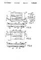
- FIG. 5is a partial view of the mounting system partially cut-away taken along line 5--5 of FIG. 1 showing the visor when in the storage position;
- FIG. 6is a cross-sectional view taken along line 6--6 of FIG. 5 showing the positioning of the first clip relative to the pivot in the detent position when the visor is in the storage position;
- FIG. 7is a cross-sectional view taken along the line 7--7 of FIG. 5 when the visor is in the storage position;
- FIG. 8is a view of the mounting system shown in FIG. 5 showing the housing when the visor is positioned in either the first and second use positions;
- FIG. 9is a cross-sectional view taken along line 9--9 of FIG. 8 showing the positioning of the first clip relative to the pivot shaft when the visor is positioned in either of the first and second use positions.
- FIGS. 1-9shows a mounting system, generally indicated at 10.
- the mounting system 10has a visor 12, a mounting bracket 14 and a block 16.
- the mounting bracket 14is generally triangular in shape and is affixed to a headliner AA of the vehicle by means of a plurality of screws 15 or the like.
- An immovable pivot shaft 18is affixed to the mounting bracket 14 and extends outwardly therefrom.
- the pivot shaft 18is generally L-shaped. However, it is possible to utilize a straight pivot shaft (not shown) rather than the generally L-shaped pivot shaft 18 described in the preferred embodiment.
- the block 16is generally rectangular in shape.
- the block 16is generally hollow having open first and second ends 17, 19.
- a barrel 20is affixed to the block and projects outwardly therefrom.
- the barrelhas a tapered section 22 adjacent the free end of the barrel.
- the visor 12defines a cut-out 24 on that portion of the visor adjacent the mounting bracket 14.
- the cut-out 24is adapted to accommodate the block 16 enabling the visor 12 to lay generally in the plane of the headliner AA when the visor is in the storage position.
- the cut-out 24defines a bore 26 which runs generally perpendicular to the longitudinal axis of the visor. Bore 26 is adapted to pivotally receive the barrel 20 of the block 16.
- An indentation 28is located within the bore 26 which cooperates with a shoulder in the tapered section 22 of the barrel in order to pivotally retain the barrel 20 within the bore 26 to enable the visor 12 to pivot relative to the block 16 between the first use position shown in FIG. 2 and the second use position shown in FIG. 3.
- the pivot shaft 18has a first flat surface 30 and a second flat surface 32 located on opposite sides and opposite ends of the pivot shaft.
- the pivot shaft 18also has a tapered end 34 and an annular groove 36 which is located opposite the tapered end 34.
- the pivot shaft 18cooperates with a housing 38 and is secured thereto by a first clip 40 and a second clip 42.
- the housing 38has a first aperture 44 and a second aperture 46 located at opposite ends of the housing 38.
- the first aperture 44is relatively larger in diameter than the second aperture 46.
- the second aperture 46has a diameter which is adapted to receive the tapered end 34 of the pivot shaft 18 but which prevents the remainder of pivot shaft 18 from being inserted within the second aperture 46 to prevent axial movement of the visor 12 relative to the pivot shaft 18 in a first direction.
- the housing 38also has an upper ridge 48 which cooperates to properly seat the first clip 40.
- a lower ridge 50is provided on the housing 38 to properly seat the second clip 42.
- the first clip 40is generally U-shaped and has a first leg 52 and a second leg 54. Each of the first leg and the second leg have a cut-out 56 and a tang 58 located at opposite sides and opposite ends of their respective first leg and second leg.
- the second clip 42is also generally U-shaped and has a first leg 60 and a second leg 62.
- a catch 64is located at opposite ends of the second clip, first leg 60 and the second clip, second leg 62 so as to correspond with the tang 58 located on the first clip, first leg 52 and the first clip, second leg 54 so as to pivotally affix the pivot shaft 18 within the housing 38.
- Annular groove 36cooperates with the internal surface of the tang 58 for limiting axial movement of the visor 12 relative to the pivot shaft 18 in a second direction.
- the entire sub-assemblyis inserted within the block 16 for mounting the visor 12 to the vehicle.
- the blockis configured to snugly receive and contain the sub-assembly during operation of the visor between positions. This self-contained sub-assembly presents an appealing appearance to the vehicle occupants.
- pivot shaft 18is inserted within the housing 38.
- the first clip and second clipare then mounted on the housing 38 around the pivot shaft 18.
- the sub-assemblyis then inserted within the block 16 which is mounted to the visor 12.
- the visoroverlays the headliner AA in the storage position such that the detent is located to retain the visor in the storage position as shown in FIG. 1.
- the block 16 and the visor 12are pivoted about the pivot shaft 18 so as to overlay the windshield BB as shown in FIG. 2.
- the visor 12is pivoted relative to the block 16 by having the visor 12 pivot about the barrel 20 so as to overlay the adjacent side window CC as shown in FIG. 3.
- the visor 12has a flexible end portion 13 which enables the visor 12 to overlay the adjacent side window CC in response to movement of the visor about the block 16.
- the effective length of the visor overlaying the adjacent side window CCis slightly reduced because of the pivoting of the visor about the block rather than the pivot shaft 18 pivoting about the mounting bracket 14. This slight reduction in effective length of the area covered by the visor 12 results in significant glare protection while still allowing the vehicle operator to look out of the rear portion of the side window CC when desired, such as to ensure that there is no car in his blind spot.
Landscapes
- Engineering & Computer Science (AREA)
- Mechanical Engineering (AREA)
- Pivots And Pivotal Connections (AREA)
Abstract
Description
Claims (19)
Priority Applications (1)
| Application Number | Priority Date | Filing Date | Title |
|---|---|---|---|
| US07/975,094US5280988A (en) | 1992-11-12 | 1992-11-12 | Multi-pivoting arrangement for visor |
Applications Claiming Priority (1)
| Application Number | Priority Date | Filing Date | Title |
|---|---|---|---|
| US07/975,094US5280988A (en) | 1992-11-12 | 1992-11-12 | Multi-pivoting arrangement for visor |
Publications (1)
| Publication Number | Publication Date |
|---|---|
| US5280988Atrue US5280988A (en) | 1994-01-25 |
Family
ID=25522696
Family Applications (1)
| Application Number | Title | Priority Date | Filing Date |
|---|---|---|---|
| US07/975,094Expired - Fee RelatedUS5280988A (en) | 1992-11-12 | 1992-11-12 | Multi-pivoting arrangement for visor |
Country Status (1)
| Country | Link |
|---|---|
| US (1) | US5280988A (en) |
Cited By (9)
| Publication number | Priority date | Publication date | Assignee | Title |
|---|---|---|---|---|
| US5366265A (en)* | 1992-01-15 | 1994-11-22 | Fico I.I.M.,S.A. | Spring hinge for automobile sunvisors |
| US5470123A (en)* | 1995-02-10 | 1995-11-28 | Prince Corporation | Visor bracket |
| US5577792A (en)* | 1995-02-21 | 1996-11-26 | Prince Corporation | Multiple visor system with aligned pivot axes |
| US5871252A (en)* | 1996-07-30 | 1999-02-16 | Lear Corporation | Telescopic sunvisor |
| US6007135A (en)* | 1997-06-27 | 1999-12-28 | Rosen Product Development, Inc. | Sun visor monorail system with locking carriage assembly |
| US6131986A (en)* | 1997-09-18 | 2000-10-17 | Rosen Products Llc | Sun visor assembly with finger-operable pivot lock |
| US20050206187A1 (en)* | 2002-06-26 | 2005-09-22 | Kyowa Sangyo Co., Ltd | Vehicle sun visor |
| US20060175862A1 (en)* | 2005-02-10 | 2006-08-10 | Kyowa Sangyo Co., Ltd | Vehicle sun visors |
| US20090152892A1 (en)* | 2005-06-02 | 2009-06-18 | Audi Ag | Sun Visor For A Motor Vehicle |
Citations (9)
| Publication number | Priority date | Publication date | Assignee | Title |
|---|---|---|---|---|
| US2965415A (en)* | 1958-06-30 | 1960-12-20 | Dryden Eva | Multiple shield sun visor for vehicles |
| US3825296A (en)* | 1972-04-24 | 1974-07-23 | S Peterson | Anti-glare system for motor vehicles |
| US4148519A (en)* | 1977-11-11 | 1979-04-10 | General Motors Corporation | Sunshade support assembly |
| US4176875A (en)* | 1978-06-27 | 1979-12-04 | Dow Walter K | Novel windshield visor support and adapter |
| US4489974A (en)* | 1982-09-27 | 1984-12-25 | Warhol John G | Visor assembly including friction mount |
| US4610477A (en)* | 1984-11-09 | 1986-09-09 | Gebr. Happich Gmbh | Bracket for sun visor for automotive vehicles with means for excluding molding foam |
| US4925233A (en)* | 1987-12-28 | 1990-05-15 | Prince Corporation | Adjustable visor |
| US5011211A (en)* | 1988-04-29 | 1991-04-30 | Autopart Sweden Ab | Sun visor for motor vehicles |
| US5011213A (en)* | 1988-09-03 | 1991-04-30 | Daimler-Benz Ag | Swivel bearing for a sun visor |
- 1992
- 1992-11-12USUS07/975,094patent/US5280988A/ennot_activeExpired - Fee Related
Patent Citations (9)
| Publication number | Priority date | Publication date | Assignee | Title |
|---|---|---|---|---|
| US2965415A (en)* | 1958-06-30 | 1960-12-20 | Dryden Eva | Multiple shield sun visor for vehicles |
| US3825296A (en)* | 1972-04-24 | 1974-07-23 | S Peterson | Anti-glare system for motor vehicles |
| US4148519A (en)* | 1977-11-11 | 1979-04-10 | General Motors Corporation | Sunshade support assembly |
| US4176875A (en)* | 1978-06-27 | 1979-12-04 | Dow Walter K | Novel windshield visor support and adapter |
| US4489974A (en)* | 1982-09-27 | 1984-12-25 | Warhol John G | Visor assembly including friction mount |
| US4610477A (en)* | 1984-11-09 | 1986-09-09 | Gebr. Happich Gmbh | Bracket for sun visor for automotive vehicles with means for excluding molding foam |
| US4925233A (en)* | 1987-12-28 | 1990-05-15 | Prince Corporation | Adjustable visor |
| US5011211A (en)* | 1988-04-29 | 1991-04-30 | Autopart Sweden Ab | Sun visor for motor vehicles |
| US5011213A (en)* | 1988-09-03 | 1991-04-30 | Daimler-Benz Ag | Swivel bearing for a sun visor |
Cited By (12)
| Publication number | Priority date | Publication date | Assignee | Title |
|---|---|---|---|---|
| US5366265A (en)* | 1992-01-15 | 1994-11-22 | Fico I.I.M.,S.A. | Spring hinge for automobile sunvisors |
| US5470123A (en)* | 1995-02-10 | 1995-11-28 | Prince Corporation | Visor bracket |
| US5577792A (en)* | 1995-02-21 | 1996-11-26 | Prince Corporation | Multiple visor system with aligned pivot axes |
| US5871252A (en)* | 1996-07-30 | 1999-02-16 | Lear Corporation | Telescopic sunvisor |
| US6007135A (en)* | 1997-06-27 | 1999-12-28 | Rosen Product Development, Inc. | Sun visor monorail system with locking carriage assembly |
| US6131986A (en)* | 1997-09-18 | 2000-10-17 | Rosen Products Llc | Sun visor assembly with finger-operable pivot lock |
| US20050206187A1 (en)* | 2002-06-26 | 2005-09-22 | Kyowa Sangyo Co., Ltd | Vehicle sun visor |
| US7066522B2 (en)* | 2002-06-26 | 2006-06-27 | Kyowa Sangyo Co., Ltd. | Vehicle sun visor |
| US20060175862A1 (en)* | 2005-02-10 | 2006-08-10 | Kyowa Sangyo Co., Ltd | Vehicle sun visors |
| US7144062B2 (en)* | 2005-02-10 | 2006-12-05 | Kyowa Sangyo Co., Ltd. | Vehicle sun visors |
| US20090152892A1 (en)* | 2005-06-02 | 2009-06-18 | Audi Ag | Sun Visor For A Motor Vehicle |
| US7954875B2 (en)* | 2005-06-02 | 2011-06-07 | Audi Ag | Sun visor for a motor vehicle |
Similar Documents
| Publication | Publication Date | Title |
|---|---|---|
| US5580117A (en) | Attachable and extendible sun visor for increased and convenient sun protection in an automobile | |
| US6189947B1 (en) | Sun visor extension device | |
| US4925233A (en) | Adjustable visor | |
| US5417466A (en) | Sun visor system | |
| US5645308A (en) | Sliding visor | |
| US6979042B2 (en) | Automotive sun visor device | |
| US3556585A (en) | Sun visor,especially at the windshield of motor vehicles | |
| JPS62163820A (en) | Visorsystem | |
| US5871252A (en) | Telescopic sunvisor | |
| US5280988A (en) | Multi-pivoting arrangement for visor | |
| US2719691A (en) | Adjustable rear view mirror assembly for vehicles | |
| US6547308B2 (en) | Visor mounting assembly | |
| US4690450A (en) | Visor system | |
| US5538311A (en) | Visor mounting bracket with integral storage | |
| US4085665A (en) | Adjustable automobile vent | |
| US5182675A (en) | Pivot down articulated mirror | |
| US5015027A (en) | Sun visor | |
| US4821374A (en) | Hinge assembly for vehicle visor and other vehicle accessories | |
| US7954875B2 (en) | Sun visor for a motor vehicle | |
| US4762359A (en) | Visor system | |
| US4703972A (en) | Rear seat automobile sun visor-mirror assembly | |
| US5244244A (en) | Dual visor design for a vehicle | |
| US5431473A (en) | Mirror cover and visor extender | |
| US5765899A (en) | Lockable sliding visor | |
| US5748395A (en) | Rear view mirror with stowable dual view mirror |
Legal Events
| Date | Code | Title | Description |
|---|---|---|---|
| AS | Assignment | Owner name:PLASTA FIBER INDUSTRIES CORP., MICHIGAN Free format text:ASSIGNMENT OF ASSIGNORS INTEREST.;ASSIGNOR:GUTE, ROBERT M.;REEL/FRAME:006345/0557 Effective date:19921105 | |
| AS | Assignment | Owner name:AUTOMOTIVE INDUSTRIES MANUFACTURING, INC., MICHIGA Free format text:ASSIGNMENT OF ASSIGNORS INTEREST;ASSIGNOR:PLASTA FIBER INDUSTRIES CORP. (AN ASSUMED NAME FOR PF ACQUISITION CO.);REEL/FRAME:007846/0904 Effective date:19960301 | |
| AS | Assignment | Owner name:AUTOMOTIVE INDUSTRIES MANUFACTURING, INC., MICHIGA Free format text:ASSIGNMENT OF ASSIGNORS INTEREST;ASSIGNOR:PLASTA FIBER INDUSTRIES CORP. (AN ASSUMED NAME FOR PF ACQUISITION CO.);REEL/FRAME:007945/0083 Effective date:19960301 | |
| FPAY | Fee payment | Year of fee payment:4 | |
| FEPP | Fee payment procedure | Free format text:PAYOR NUMBER ASSIGNED (ORIGINAL EVENT CODE: ASPN); ENTITY STATUS OF PATENT OWNER: LARGE ENTITY | |
| FPAY | Fee payment | Year of fee payment:8 | |
| AS | Assignment | Owner name:LEAR CORPORATION, MICHIGAN Free format text:MERGER;ASSIGNOR:LEAR TECHNOLOGY CORPORATION;REEL/FRAME:014196/0260 Effective date:19981231 Owner name:LEAR TECHNOLOGY CORPORATION, MICHIGAN Free format text:CHANGE OF NAME;ASSIGNOR:AUTOMOTIVE INDUSTRIES MANUFACTURING, INC.;REEL/FRAME:014196/0256 Effective date:19980226 | |
| REMI | Maintenance fee reminder mailed | ||
| LAPS | Lapse for failure to pay maintenance fees | ||
| STCH | Information on status: patent discontinuation | Free format text:PATENT EXPIRED DUE TO NONPAYMENT OF MAINTENANCE FEES UNDER 37 CFR 1.362 | |
| FP | Lapsed due to failure to pay maintenance fee | Effective date:20060125 |