US5280876A - Limited restriction quick disconnect valve - Google Patents
Limited restriction quick disconnect valveDownload PDFInfo
- Publication number
- US5280876A US5280876AUS08/036,972US3697293AUS5280876AUS 5280876 AUS5280876 AUS 5280876AUS 3697293 AUS3697293 AUS 3697293AUS 5280876 AUS5280876 AUS 5280876A
- Authority
- US
- United States
- Prior art keywords
- coupling
- retaining ring
- resilient sleeve
- quick disconnect
- plug
- Prior art date
- Legal status (The legal status is an assumption and is not a legal conclusion. Google has not performed a legal analysis and makes no representation as to the accuracy of the status listed.)
- Expired - Fee Related
Links
- 230000008878couplingEffects0.000claimsabstractdescription63
- 238000010168coupling processMethods0.000claimsabstractdescription63
- 238000005859coupling reactionMethods0.000claimsabstractdescription63
- 230000006835compressionEffects0.000claims1
- 238000007906compressionMethods0.000claims1
- 230000001954sterilising effectEffects0.000abstractdescription44
- 238000004659sterilization and disinfectionMethods0.000abstractdescription44
- 238000007789sealingMethods0.000abstractdescription10
- 238000004140cleaningMethods0.000abstractdescription7
- 239000003795chemical substances by applicationSubstances0.000description10
- 230000000249desinfective effectEffects0.000description3
- 239000007788liquidSubstances0.000description3
- CBENFWSGALASAD-UHFFFAOYSA-NOzoneChemical compound[O-][O+]=OCBENFWSGALASAD-UHFFFAOYSA-N0.000description2
- 239000000645desinfectantSubstances0.000description2
- 238000005304joiningMethods0.000description2
- 239000000463materialSubstances0.000description2
- XAGFODPZIPBFFR-UHFFFAOYSA-NaluminiumChemical compound[Al]XAGFODPZIPBFFR-UHFFFAOYSA-N0.000description1
- 238000011109contaminationMethods0.000description1
- 238000004519manufacturing processMethods0.000description1
- 239000007769metal materialSubstances0.000description1
- 238000000034methodMethods0.000description1
- 229920001296polysiloxanePolymers0.000description1
Images


Classifications
- F—MECHANICAL ENGINEERING; LIGHTING; HEATING; WEAPONS; BLASTING
- F16—ENGINEERING ELEMENTS AND UNITS; GENERAL MEASURES FOR PRODUCING AND MAINTAINING EFFECTIVE FUNCTIONING OF MACHINES OR INSTALLATIONS; THERMAL INSULATION IN GENERAL
- F16L—PIPES; JOINTS OR FITTINGS FOR PIPES; SUPPORTS FOR PIPES, CABLES OR PROTECTIVE TUBING; MEANS FOR THERMAL INSULATION IN GENERAL
- F16L37/00—Couplings of the quick-acting type
- F16L37/28—Couplings of the quick-acting type with fluid cut-off means
- F16L37/38—Couplings of the quick-acting type with fluid cut-off means with fluid cut-off means in only one of two pipe-end fittings
- A—HUMAN NECESSITIES
- A61—MEDICAL OR VETERINARY SCIENCE; HYGIENE
- A61M—DEVICES FOR INTRODUCING MEDIA INTO, OR ONTO, THE BODY; DEVICES FOR TRANSDUCING BODY MEDIA OR FOR TAKING MEDIA FROM THE BODY; DEVICES FOR PRODUCING OR ENDING SLEEP OR STUPOR
- A61M39/00—Tubes, tube connectors, tube couplings, valves, access sites or the like, specially adapted for medical use
- A61M39/22—Valves or arrangement of valves
- A61M39/26—Valves closing automatically on disconnecting the line and opening on reconnection thereof
- F—MECHANICAL ENGINEERING; LIGHTING; HEATING; WEAPONS; BLASTING
- F16—ENGINEERING ELEMENTS AND UNITS; GENERAL MEASURES FOR PRODUCING AND MAINTAINING EFFECTIVE FUNCTIONING OF MACHINES OR INSTALLATIONS; THERMAL INSULATION IN GENERAL
- F16L—PIPES; JOINTS OR FITTINGS FOR PIPES; SUPPORTS FOR PIPES, CABLES OR PROTECTIVE TUBING; MEANS FOR THERMAL INSULATION IN GENERAL
- F16L37/00—Couplings of the quick-acting type
- F16L37/08—Couplings of the quick-acting type in which the connection between abutting or axially overlapping ends is maintained by locking members
- F16L37/10—Couplings of the quick-acting type in which the connection between abutting or axially overlapping ends is maintained by locking members using a rotary external sleeve or ring on one part
- F16L37/113—Couplings of the quick-acting type in which the connection between abutting or axially overlapping ends is maintained by locking members using a rotary external sleeve or ring on one part the male part having lugs on its periphery penetrating into the corresponding slots provided in the female part
- A—HUMAN NECESSITIES
- A61—MEDICAL OR VETERINARY SCIENCE; HYGIENE
- A61M—DEVICES FOR INTRODUCING MEDIA INTO, OR ONTO, THE BODY; DEVICES FOR TRANSDUCING BODY MEDIA OR FOR TAKING MEDIA FROM THE BODY; DEVICES FOR PRODUCING OR ENDING SLEEP OR STUPOR
- A61M39/00—Tubes, tube connectors, tube couplings, valves, access sites or the like, specially adapted for medical use
- A61M39/10—Tube connectors; Tube couplings
- A61M2039/1027—Quick-acting type connectors
- A—HUMAN NECESSITIES
- A61—MEDICAL OR VETERINARY SCIENCE; HYGIENE
- A61M—DEVICES FOR INTRODUCING MEDIA INTO, OR ONTO, THE BODY; DEVICES FOR TRANSDUCING BODY MEDIA OR FOR TAKING MEDIA FROM THE BODY; DEVICES FOR PRODUCING OR ENDING SLEEP OR STUPOR
- A61M39/00—Tubes, tube connectors, tube couplings, valves, access sites or the like, specially adapted for medical use
- A61M39/22—Valves or arrangement of valves
- A61M39/26—Valves closing automatically on disconnecting the line and opening on reconnection thereof
- A61M2039/267—Valves closing automatically on disconnecting the line and opening on reconnection thereof having a sealing sleeve around a tubular or solid stem portion of the connector
- Y—GENERAL TAGGING OF NEW TECHNOLOGICAL DEVELOPMENTS; GENERAL TAGGING OF CROSS-SECTIONAL TECHNOLOGIES SPANNING OVER SEVERAL SECTIONS OF THE IPC; TECHNICAL SUBJECTS COVERED BY FORMER USPC CROSS-REFERENCE ART COLLECTIONS [XRACs] AND DIGESTS
- Y10—TECHNICAL SUBJECTS COVERED BY FORMER USPC
- Y10S—TECHNICAL SUBJECTS COVERED BY FORMER USPC CROSS-REFERENCE ART COLLECTIONS [XRACs] AND DIGESTS
- Y10S604/00—Surgery
- Y10S604/905—Aseptic connectors or couplings, e.g. frangible, piercable
Definitions
- This inventionrelates to valves and in particular to quick release valves that are suitable for use in medical instrument sterilization systems for releasably connecting sterilization agent inlet and exhaust lines to a removable primary sterilization chamber wherein medical instrument sterilization takes place.
- the valve of the present inventionemploys a resilient sleeve as the valve closure component that is itself easily removable and replaceable. After which removal the valve body and connection components are easily broken apart and have inner cavities that are essentially smooth walled and therefor are conveniently and efficiently cleaned and sterilized, presenting a significant improvement over the pneumatic valves as have formerly been utilized.
- Medical instrument sterilization systemsthat employ sterilization agent transfer lines and valve are shown in patents to Masuda, U.S. Pat. No. 5,120,512 and to Karlson, U.S. Pat. No. 5,069,880.
- a plurality of container and chamber arrangements for use in sterilization processes that utilize treated ozone as the effluentare shown in patents to Anderson, et al, U.S. Pat. No. 5,118,471; and to Lutz, U.S. Pat. No. 5,087,419. None of which systems, however, have utilized a quick release valve that is configured like that of the present invention.
- Another object of the present inventionis to provide a quick disconnect valve that is readily broken apart and includes a resilient sleeve as a closure member that can be removed and replaced, with the valve body components having essentially smooth interior wall surfaces that are easily cleaned and disinfected.
- Another object of the present inventionis to provide a quick disconnect valve for inclusion between inlet and outlet sterilization agent transfer lines and a primary sterilization chamber that is easily releasable by turning of single connection sleeve, separating the valve forward and rear components.
- Another object of the present inventionis to provide a quick disconnect valve that is capable of being swiftly broken down into its component parts to expose the resilient sleeve closure member that can be easily removed and replaced after the valve components have been cleaned and disinfected for remounting in the primary sterilization chamber and connection to the sterilization agent inlet and exhaust lines.
- Still another object of the present inventionis to a quick disconnect valve that is functionally unique over earlier pneumatic valves in that it does not involve a mechanical closure arrangement, and rather employs a replaceable resilient sleeve as the closure member that, when relaxed, as when the valve body components are separated, closes and seals off side ports that open into a passage to the primary sterilization chamber, maintaining that chamber in a sealed attitude, and when the valve body components are connected together the ends of the resilient sleeve are compressed together flexing the sleeve middle portion so as to lift the sleeve off of the side ports that are thereby opened to allow a flow through the valve.
- Still another object of the present inventionis to provide a make before break quick disconnect valve that has no moving parts, is a single step open or close arrangement that provides a secure sealed closure when the valve body components are broken apart and is open therethrough when the valve body components are recoupled together.
- Still another object of the present inventionis to provide a quick disconnect valve that is easily and inexpensively manufactured from light weight metal materials and utilizes a thick walled resilient tube section as the valve closure member that is easily and inexpensively replaced after each use.
- the inventionis in a limited restriction quick disconnect valve that is particularly well suited for providing a quick release coupling of a primary sterilization chamber to sterilization agent inlet and exhaust lines in a medical instrument sterilization system.
- the quick disconnect valve of the inventioncould be employed in any number of applications where it is desired to provide a quick release valve whose components are easily connected together, is simple and inexpensive to manufacture and can be easily and reliably cleaned.
- the quick disconnect valve of the inventionincludes a female bulk head connector arranged for mounting into a container wall, such as the wall of a primary sterilization chamber of a medical instrument sterilization system.
- a valve closure devicethat is a section of a resilient sleeve is contained within the female bulk head connector, mounted over side ports that are formed in a stem of a forward end section of the female connector.
- a retaining ringthat includes a keeper turned therein, is itself turned onto the stem.
- the resilient tube endsare contained between an interior wall of the female connector forward end and an opposing internal face of the keeper, the resilient tube interior surface closing over the stem side ports.
- a coupling ringthat includes detents that project inwardly at space points from its inner wall that ar for traveling into and along locking slots that have been formed in the retaining ring outer surface.
- the coupling ringin arranged with a cylindrical shaft that is open therethrough, and the section is for mounting onto the end of a transfer line.
- the coupling ringfor coupling onto the retaining ring of the bulk head female connector, the cylindrical shaft end for traveling axially into the retaining ring, engaging and compressing the resilient sleeve end, bowing it outwardly around its mid portion to lift the resilient sleeve off of the side ports, open the valve to the liquid or gas transfer line.
- the quick disconnect valve of the inventioncan be quickly disassembled. Where valve interior cleaning and disinfecting is required, the resilient tube can be conveniently removed and replaced, opening the valve body components that have essentially smooth inner walls without crevices and therefore lend themselves to being cleaned and disinfected after use.
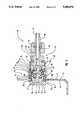
- FIG. 1shows an exploded side elevation view of a limited restriction quick disconnect valve of the invention
- FIG. 2shows a profile perspective view of the assembled quick disconnect valve of FIG. 1, with a bulk head female connection end shown maintained in an upright wall, that should be taken as a wall of a container, with the other valve end shown aligned for receiving a connector fitting mounted onto an end of a transfer line turned thereon;
- FIG. 3shows a profile sectional view taken along the line 3--3 of FIG. 2, showing the valve body sections separated, with a coupling ring separated from a retaining ring, and showing a resilient sleeve arranged on a stem within the valve bulk head female connector, as the valve closure device, showing the resilient sleeve in a relaxed state relaxed closing off side ports in the stem of the bulk head female connection;
- FIG. 4shows a view like FIG. 3 except the coupling ring is shown turned onto the retaining ring, showing an end of a cylindrical shaft mounted axially in the coupling right, that is open therethrough to the transfer line, in engagement with the resilient sleeve end, compressing that resilient sleeve to bow it outwardly around its middle, and showing the resilient sleeve inner surface lifted off of the stem side ports, allowing a flow to pass from the transfer line, through the side ports into the container, illustrated as a wall section.
- FIG. 1shows a profile perspective exploded view of a limited restriction quick disconnect valve 10 of the invention, hereinafter referred to as valve.
- the valve 10as shown best in FIG. 2, is preferably for mounting in the side of a vessel or container, illustrated as a wall 11, for exhausting from or passing a flow of a liquid or gas into the container 11.
- the valveis arranged to be quickly connected and disconnected for joining the container to a transfer line 12, and provides a closure device that is removable and replaceable after each use, as needed.
- the valve of the inventionis particularly well suited for use with a medical instrument sterilization system for releasably connecting a primary sterilization chamber to sterilization inlet and outlet lines. Though, it should be understood, the valve 10 can be used for any number of applications as a quick disconnect valve, within the scope of this disclosure.
- the valve 10includes a bulk head female connector section 13, that receives, as illustrated in FIGS. 2 and 4, a coupling connector section 14 fitted thereto for connecting the valve 10 sections together so as to pass a flow between the container 11 and transfer line 12.
- the bulk head female connector section 13includes a container mount 15 that has a flat forward face 16 and is stepped axially inwardly from the center of a rear face into a cylinder 17.
- the cylinder 17is threaded at 18 around a mid section and is stepped axially inwardly, at a rear face thereof, into a stem 19.
- the stem 19extends axially from the container mount 15 and is closed across its rear end 20.
- the stem 19includes one or more side ports 21 that open to a center longitudinal opening 22 that opens in the center of the container mount 15 flat forward face 16.
- a resilient sleeve 23is shown best in FIG. 3, fitted over the stem 19 that is in a relaxed attitude and is shown in FIG. 4 as having been a compressed, showing the resilient sleeve bowed outwardly around its middle.
- the resilient sleeve 23, as shown in FIG. 3,is relaxed with the interior wall thereof in covering attitude over the stem side ports 21. Whereas, as shown in FIG. 4, with the resilient sleeve bowed outwardly around its middle, the interior wall is lifted off the side ports 21, opening them to a flow therethrough.
- the bulk head female connector section 13 and coupling connector section 1provides for bowing of the resilient sleeve 23, as shown in FIG. 4, opening the valve 10 to pass a flow therethrough, as set out in detail hereinbelow.
- a resilient sealing gasket 24is fitted over the stem 19 and cylinder 17 to engage a rear face of the container mount 15, and the stem and cylinder are fitted into a hole 11a formed through the container 11 wall, the sealing gasket 24 to engage a container inner face 11b around the hole 11a.
- a retaining ring 25is fitted thereto.
- the retaining ring 25is threaded internally along its length and is turned onto the cylinder 17 threads 18, until a retaining ring forward end 25a engages a container outer face 11c around hole 11.
- retaining ring 25turning on the cylinder 17 threads 18 draws the container mount thereto, compressing the sealing gasket 24 against the container inner face 11b to provide for sealing of the container mount 15 in the wall of container 11.
- a retaining ring keeper 26that is threaded around a forward end 27 thereof, is turned into the retaining ring 25, onto the retaining ring internal threads. From the threaded forward end 27 rearwardly the keeper 26 is stepped outwardly into a finger engaging portion 28 that is preferably appropriately cross hatched for gripping by an operator for turning the keeper 26 into the retaining ring 25 internal threads.
- the keeper 26is centrally open axially, and that passage wall is sloped at 29, from a greater diameter at approximately its middle area, to a lesser diameter opening 30 at the keeper rear face.
- the keeper opening 30is of a lesser diameter to that of the resilient sleeve 23 and is for retaining an end of that resilient sleeve 23 in a cavity that is formed within the retaining ring 25, between the keeper 26 sloping inner wall 29 and a cavity 15a in the container mount 15 rear face that is formed the stem 18.
- Coupling connector section 14that is coupled the transfer line it provided for coupling to the bulk head female connector section 13.
- the coupling connectorincludes a coupling ring 35 on a forward end thereof.
- the coupling ring 35includes a joining ring 36 that has a smooth inner wall 37 and is of a diameter to fit over the retaining ring 25.
- Detents 38are formed in the coupling ring 35 inner wall 37 to extend inwardly, at spaced intervals, from around that inner wall.
- the coupling ring 35is for sliding over and locking to the retaining ring 25, with the coupling ring detents 38 to align with and travel into a groove opening 31, that is formed as a groove in the retaining ring 25 outer surface, in the shape of a right triangle.
- each detent 38will slide along a groove sloping side 32, traveling between that sloping side 32 and a straight groove side 33, that is the triangle base, to a groove end 34 that is the junction of the groove sloping and straight sides.
- the valve 10 bulk head female connector section 13 and the coupling connector section 14are thereby joined together as shown in FIGS. 2 and 4.
- the coupling ring 35is essentially a thin walled cylindrical shell that is open therethrough.
- the coupling ring 35includes the roughened surface 36 and is stepped inwardly, at approximately a mid point into a cylindrical body section 39.
- the cylindrical body section 39is turned inwardly into a right angle foot 40 as its rear end, which right angle foot 40 is open through the center thereof.
- the right angle footis for fitting in sealing, arrangement into a groove 42 that has been formed around a mid-section of a plug 41 that formes the rear portion of the coupling ring section 14.
- a forward end of plug 41is shown, in FIGS.
- cylindrical shaft 43that is of a diameter to travel through the opening 30 in the keeper 26 rear end, traveling between the ends of the sloping surface 29 that contain the end of the rear end of the resilient sleeve 23.
- the cylindrical shaft 43 forward end faceis formed to have a concave to flat section 45 formed around the outer one quarter to one third of the shaft end face to the shaft circumference and slopes therefrom toward the longitudinal axis outwardly into a frustum of a cone section 44 that intersects a longitudinal hole through the plug 41.
- the coupling ring 35is turned onto the retaining ring 25 the cylinder shaft 43 frustum of a cone section 44 travels into the resilient sleeve 23 center opening.
- the resilient sleeve end areais captured by the shaft face flat section 45, prohibiting passage of the cylindrical shaft into the resilient sleeve as the resilient sleeve is uniformly compressed against its opposite end that is seated against the container mount 15 cavity 15a.
- the resilient sleeveWith continued movement of the shaft 41 against the resilient sleeve 23 end, the resilient sleeve is further compressed, bowing the middle sleeve area outwardly, as shown in FIG. 4, and lifting the sleeve inner surface off of the side ports 21. Uncovering of the side ports 21 opens the stem 19 longitudinal passage 22 to the longitudinal passage through the plug 41.
- the plug 41 rear end 46is threaded for receiving a coupling nut 47 turned thereon the coupling nut 47, in turn, is fitted onto to a spindle 48 that connects to the transfer line 12, the nut 47 to turn freely on the spindle 48 and includes a sealing washer or gasket between which the opposing spindle face and a rear face of the plug 41.
- the nut 47 and spindle 48 mountingis essentially a standard pressure line coupling. With the nut 47 arranged to turn freely on the spindle, the coupling ring 35 is allowed to turn onto the retaining ring 25, as described above.
- the container mount 15 flat forward face section 16includes a pair of straight notches 16a that are formed in opposite sides of the section and are for receiving a wrench type spanning tool, not show, fitted thereacross.
- the stem 19with the resilient sleeve 23 fitted thereto, that extends axially from the cylinder 17 whereon is positioned the sealing gasket 24, is fitted through the container wall hole 11a.
- a spanning tool, not shown,is fitted onto notches 16a, so as to hold the container mount 15 in place, and the retaining ring 25 is turned over the cylinder 17 threads 18.
- the retaining ring 25is turned onto cylinder threads 18 to where the retaining ring forward face 25a engages the container wall surface 11c around the container hole 11a.
- the container mount rear face 16ais thereby drawn against the sealing gasket 24, compressing the gasket to where it seals the container mount 15 in the container hole 11a.
- Assembly of the bulk head female connector 13 in the container wall 11is completed by turning of the keeper 26 onto the retaining ring 25 inner threads, the keeper sloping rear wall 29 engaging and fitting snugly against the resilient sleeve 23 end, as shown in FIG. 3.
- the coupling ring 35can then be fitted onto the retaining ring 25 and turned.
- the retaining ring detents 38travel into the groove 31 opening, along the groove sloping side 32 to the groove end 34.
- a connection of the coupling ring 35 onto the retaining ring 25is thereby provided, in which connection, as shown in FIG. 4, the cylindrical shaft 43 end face engages the resilient sleeve 23 end and compresses it to where it bows outwardly around its mid-opposite section.
- the resilient sleeve inner surfaceis thereby lifted off of the stem side ports 21, opening the valve to passage between the container 11 and transfer line 12.
- the container 11is a primary sterilization chamber of a medical instrument sterilization system
- the connecting ring 35can be turned off of the retaining ring 25, releasing the compressive force off from the resilient sleeve 23 end.
- the resilient sleeveis thereby relaxed to the attitude shown in FIG. 3, the resilient sleeve inner surface engaging to seal over the side ports 21.
- the primary sterilization chambercan then be moved, in a sealed state, to an operating room, or the like, where it is opened and the sterilized medical tools removed for use.
- the primary sterilization chamber that the valve bulk head female connector 13 is mounted tomay be cleaned and disinfected, which cleaning and disinfecting may include cleaning the bulk head female connector 13.
- the resilient sleeve 23may be removed and replaced. Which removal and replacement involves turning the keeper 28 out of the retaining ring 25 to afford access to the resilient sleeve 23 that can then be pulled off from the stem 19 and replaced with a new resilient sleeve 23.
- the bulk head female connectoris open and has essentially smooth interior surface that can be conveniently swabbed out with a disinfectant, or the like.
- the coupling ring 35is when removed from the retaining ring 25 is essentially open, contains the cylindrical shaft 43 only, and can therefore also be conveniently swabbed out with a disinfectant.
- the retaining ring 25can be turned off of the threads 18 of cylinder 17, releasing the container mount 15, the bulk head female connector 13 thereby broken into individual components that are easily sterilized and then reassembled.
- valve 10 of the inventionhas been described as being for use as a quick disconnect valve for connecting a primary sterilization chamber into a transfer line for transferring a sterilization agent. It should, however, be understood that the valve 10 is suitable for use as a replacement for most quick disconnect valves as are currently available. It should therefore be understood that the described use for valve 10 set out herein is made for example only.
- the components of the limited restriction quick disconnect valve of the inventionhave been fabricated from a light weight aluminum metal, and a resilient tube manufactured from a silicone plastic material has been utilized as the resilient tube 23,
- a resilient tube manufactured from a silicone plastic materialhas been utilized as the resilient tube 23
- other appropriate materialscould be used to construct components of the valve 10 of the invention, within the scope of this disclosure.
Landscapes
- Engineering & Computer Science (AREA)
- General Engineering & Computer Science (AREA)
- Health & Medical Sciences (AREA)
- Mechanical Engineering (AREA)
- Heart & Thoracic Surgery (AREA)
- Anesthesiology (AREA)
- Pulmonology (AREA)
- Biomedical Technology (AREA)
- Hematology (AREA)
- Life Sciences & Earth Sciences (AREA)
- Animal Behavior & Ethology (AREA)
- General Health & Medical Sciences (AREA)
- Public Health (AREA)
- Veterinary Medicine (AREA)
- Quick-Acting Or Multi-Walled Pipe Joints (AREA)
Abstract
Description
Claims (13)
Priority Applications (3)
| Application Number | Priority Date | Filing Date | Title |
|---|---|---|---|
| US08/036,972US5280876A (en) | 1993-03-25 | 1993-03-25 | Limited restriction quick disconnect valve |
| PCT/US1994/003191WO1994021954A1 (en) | 1993-03-25 | 1994-03-23 | Limited restriction quick disconnect valve |
| AU64151/94AAU6415194A (en) | 1993-03-25 | 1994-03-23 | Limited restriction quick disconnect valve |
Applications Claiming Priority (1)
| Application Number | Priority Date | Filing Date | Title |
|---|---|---|---|
| US08/036,972US5280876A (en) | 1993-03-25 | 1993-03-25 | Limited restriction quick disconnect valve |
Publications (1)
| Publication Number | Publication Date |
|---|---|
| US5280876Atrue US5280876A (en) | 1994-01-25 |
Family
ID=21891727
Family Applications (1)
| Application Number | Title | Priority Date | Filing Date |
|---|---|---|---|
| US08/036,972Expired - Fee RelatedUS5280876A (en) | 1993-03-25 | 1993-03-25 | Limited restriction quick disconnect valve |
Country Status (3)
| Country | Link |
|---|---|
| US (1) | US5280876A (en) |
| AU (1) | AU6415194A (en) |
| WO (1) | WO1994021954A1 (en) |
Cited By (88)
| Publication number | Priority date | Publication date | Assignee | Title |
|---|---|---|---|---|
| US5533708A (en)* | 1992-06-04 | 1996-07-09 | Vernay Laboratories, Inc. | Medical coupling site valve body |
| US5549577A (en)* | 1993-12-29 | 1996-08-27 | Ivac Corporation | Needleless connector |
| US5645608A (en) | 1996-01-03 | 1997-07-08 | Cooper; Theodore R. | Cold water wash method |
| US5755425A (en)* | 1996-06-20 | 1998-05-26 | The United States Of America As Represented By The Secretary Of The Navy | Fitting for flexible fuel bladder |
| US5788215A (en)* | 1995-12-29 | 1998-08-04 | Rymed Technologies | Medical intravenous administration line connectors having a luer or pressure activated valve |
| US5807345A (en)* | 1995-06-30 | 1998-09-15 | Abbott Laboratories | Luer cap for terminally sterilized syringe |
| US5833213A (en)* | 1995-12-29 | 1998-11-10 | Rymed Technologies, Inc. | Multiple dose drug vial adapter for use with a vial having a pierceable septum and a needleless syringe |
| US5868126A (en)* | 1996-08-12 | 1999-02-09 | The Coleman Company, Inc. | LPG canister connector for combustion appliance |
| US5954313A (en)* | 1995-12-29 | 1999-09-21 | Rymed Technologies, Inc. | Medical intravenous administration line connectors having a luer activated valve |
| US5954044A (en)* | 1996-08-12 | 1999-09-21 | The Coleman Company Inc. | Connector for securing a conduit to a fluid source |
| US5957898A (en) | 1997-05-20 | 1999-09-28 | Baxter International Inc. | Needleless connector |
| US6006387A (en) | 1995-11-30 | 1999-12-28 | Cyclo3Pss Textile Systems, Inc. | Cold water ozone disinfection |
| US6035892A (en)* | 1998-08-20 | 2000-03-14 | Penn Troy Machine Co., Inc. | Telescoping valve having improved seal |
| US6068011A (en)* | 1993-10-13 | 2000-05-30 | Paradis; Joseph R. | Control of fluid flow |
| US6257550B1 (en)* | 2000-04-06 | 2001-07-10 | Intex Recreation Corp. | Drain valve adapter for aqueous container |
| US6261282B1 (en) | 1997-05-20 | 2001-07-17 | Baxter International Inc. | Needleless connector |
| US6293293B1 (en)* | 1998-05-12 | 2001-09-25 | Itw New Zealand Limited | Valve |
| US20010049508A1 (en)* | 1996-12-16 | 2001-12-06 | Fangrow Thomas F. | Medical valve with positive flow characteristics |
| US6458398B1 (en) | 1999-10-18 | 2002-10-01 | Eco Pure Food Safety Systems, Inc. | Cold water disinfection of foods |
| US20030050610A1 (en)* | 2001-08-22 | 2003-03-13 | Newton Brian L. | Medical valve with expandable member |
| US20030093061A1 (en)* | 2001-11-13 | 2003-05-15 | Ganem Charles F. | Anti-drawback medical valve |
| EP1374917A1 (en)* | 2002-04-04 | 2004-01-02 | Caracciolo, Alessio Maria | Method to carry out sanitization that is disinfection and/or sterilization and/or disinfestation of limited areas with difficult or foreclosured access |
| US20040006330A1 (en)* | 2000-07-11 | 2004-01-08 | Fangrow Thomas F | Medical valve with positive flow characteristics |
| US6755391B2 (en) | 2000-10-23 | 2004-06-29 | Nypro Inc. | Anti-drawback medical valve |
| US20040133171A1 (en)* | 2002-10-29 | 2004-07-08 | Newton Brian L. | Positive push medical valve with internal seal |
| US20040199126A1 (en)* | 2001-12-07 | 2004-10-07 | Harding Weston F | Needleless luer access connector |
| US20050025686A1 (en)* | 2003-08-01 | 2005-02-03 | Steris Inc. | Method and device for deactivating items and for maintaining such items in a deactivated state |
| US20050038397A1 (en)* | 2003-07-31 | 2005-02-17 | Newton Brian L. | Anti-drawback medical valve |
| US6883778B1 (en) | 1996-11-18 | 2005-04-26 | Nypro Inc. | Apparatus for reducing fluid drawback through a medical valve |
| US20050205583A1 (en)* | 2004-02-03 | 2005-09-22 | Zf Friedrichshafen Ag | Filling valve for a pressure vessel |
| US20050222541A1 (en)* | 1996-12-16 | 2005-10-06 | Lopez George A | Positive flow valve |
| US20060161115A1 (en)* | 2004-11-05 | 2006-07-20 | Fangrow Thomas F | Soft-grip medical connector |
| US20060264841A1 (en)* | 2005-01-14 | 2006-11-23 | Cote Andrew L Sr | Valve with internal lifter |
| US20060293629A1 (en)* | 2001-11-13 | 2006-12-28 | Cote Andrew L Sr | Anti-drawback medical valve |
| US20080039802A1 (en)* | 2006-08-11 | 2008-02-14 | Nypro Inc. | Medical Valve With Expandable Member |
| US20080097407A1 (en)* | 2006-10-18 | 2008-04-24 | Michael Plishka | Luer activated device with compressible valve element |
| US20080099708A1 (en)* | 2006-10-25 | 2008-05-01 | Lee Ti-Tien | Vacuum valve device for a bag |
| US20080172005A1 (en)* | 2006-10-18 | 2008-07-17 | Jepson Steven C | Luer activated device with valve element under tension |
| US20080172003A1 (en)* | 2006-10-18 | 2008-07-17 | Michael Plishka | Luer activated device |
| US20090204080A1 (en)* | 2008-02-12 | 2009-08-13 | Baxter International Inc. | Two-way valve connector |
| EP1667736A4 (en)* | 2003-08-01 | 2009-12-02 | American Sterilizer Co | Method and device for deactivating items and for maintaining such items in a deactivated state |
| US7635357B2 (en) | 1994-06-20 | 2009-12-22 | Mayer Bruno Franz P | Needleless injection site |
| US20100036366A1 (en)* | 2006-10-12 | 2010-02-11 | Jamie Glen House | Devices for Connecting Catheter Assembly to Collection Receptacle |
| US20100065034A1 (en)* | 2006-01-27 | 2010-03-18 | The Coleman Company, Inc. | Fuel conversion adapter for a backpacking stove |
| US7753892B2 (en) | 2001-11-13 | 2010-07-13 | Nypro Inc. | Anti-drawback medical valve |
| US7753338B2 (en) | 2006-10-23 | 2010-07-13 | Baxter International Inc. | Luer activated device with minimal fluid displacement |
| US7789864B2 (en) | 1996-11-18 | 2010-09-07 | Nypro Inc. | Luer-activated valve |
| US20100249724A1 (en)* | 2009-03-30 | 2010-09-30 | Np Medical Inc. | Medical Valve with Distal Seal Actuator |
| USD644731S1 (en) | 2010-03-23 | 2011-09-06 | Icu Medical, Inc. | Medical connector |
| US8105314B2 (en) | 2006-10-25 | 2012-01-31 | Icu Medical, Inc. | Medical connector |
| US8454579B2 (en) | 2009-03-25 | 2013-06-04 | Icu Medical, Inc. | Medical connector with automatic valves and volume regulator |
| US8568371B2 (en) | 2009-06-22 | 2013-10-29 | Np Medical Inc. | Medical valve with improved back-pressure sealing |
| WO2013192592A1 (en)* | 2012-06-21 | 2013-12-27 | Robert Bosch Gmbh | Quick connect and quick disconnect system and method of manipulating a quick connect and quick disconnect system |
| US8758306B2 (en) | 2010-05-17 | 2014-06-24 | Icu Medical, Inc. | Medical connectors and methods of use |
| WO2014161846A3 (en)* | 2013-04-02 | 2014-12-11 | Parker Hannifin Manufacturing Germany GmbH & Co. KG | Fluid valve and fluid connection system |
| US20150157849A1 (en)* | 2013-12-10 | 2015-06-11 | Applied Medical Technology, Inc. | Auto-Shutoff Coupling |
| US9138572B2 (en) | 2010-06-24 | 2015-09-22 | Np Medical Inc. | Medical valve with fluid volume alteration |
| US20160040814A1 (en)* | 2013-04-18 | 2016-02-11 | Whi-Dong JUNG | Tube-fitting structure for pure-water line |
| US9414990B2 (en) | 2013-03-15 | 2016-08-16 | Becton Dickinson and Company Ltd. | Seal system for cannula |
| US9414991B2 (en) | 2013-11-06 | 2016-08-16 | Becton Dickinson and Company Limited | Medical connector having locking engagement |
| US20170043994A1 (en)* | 2015-08-13 | 2017-02-16 | David G. Kraenzle | Apparatus, systems, and methods relating to transfer of fluids to/from containers and/or storage/transport of fluids in containers |
| US9597260B2 (en) | 2013-03-15 | 2017-03-21 | Becton Dickinson and Company Ltd. | System for closed transfer of fluids |
| US9636278B2 (en) | 2013-11-06 | 2017-05-02 | Becton Dickinson and Company Limited | System for closed transfer of fluids with a locking member |
| US9642775B2 (en) | 2013-11-06 | 2017-05-09 | Becton Dickinson and Company Limited | System for closed transfer of fluids having connector |
| USD786427S1 (en) | 2014-12-03 | 2017-05-09 | Icu Medical, Inc. | Fluid manifold |
| USD793551S1 (en) | 2014-12-03 | 2017-08-01 | Icu Medical, Inc. | Fluid manifold |
| US9833605B2 (en) | 2014-04-21 | 2017-12-05 | Becton Dickinson and Company Limited | Fluid transfer device and packaging therefor |
| US9855192B2 (en) | 2014-04-21 | 2018-01-02 | Becton Dickinson and Company Limited | Syringe adapter with compound motion disengagement |
| US9895288B2 (en) | 2014-04-16 | 2018-02-20 | Becton Dickinson and Company Limited | Fluid transfer device |
| US9907887B2 (en) | 2003-11-20 | 2018-03-06 | The Henry M. Jackson Foundation For The Advancement Of Military Medicine, Inc. | Portable hand pump for evacuation of fluids |
| US9913935B2 (en)* | 2004-10-12 | 2018-03-13 | C. R. Bard, Inc. | Corporeal drainage system |
| US9980878B2 (en) | 2014-04-21 | 2018-05-29 | Becton Dickinson and Company Limited | System with adapter for closed transfer of fluids |
| US9999570B2 (en) | 2014-04-21 | 2018-06-19 | Becton Dickinson and Company Limited | Fluid transfer device and packaging therefor |
| US10022298B2 (en) | 2014-04-21 | 2018-07-17 | Becton Dickinson and Company Limited | Vial stabilizer base with vial adapter |
| US10132436B2 (en) | 2013-03-15 | 2018-11-20 | Fiskars Oyj Abp | Quick connect/disconnect adaptor system |
| US20190086012A1 (en)* | 2017-09-20 | 2019-03-21 | Gates Corporation | Quick Disconnect Coupling |
| US10286201B2 (en) | 2013-11-06 | 2019-05-14 | Becton Dickinson and Company Limited | Connection apparatus for a medical device |
| US10369349B2 (en) | 2013-12-11 | 2019-08-06 | Icu Medical, Inc. | Medical fluid manifold |
| US10376654B2 (en) | 2014-04-21 | 2019-08-13 | Becton Dickinson and Company Limited | System for closed transfer of fluids and membrane arrangements for use thereof |
| US10441507B2 (en) | 2014-04-21 | 2019-10-15 | Becton Dickinson and Company Limited | Syringe adapter with disconnection feedback mechanism |
| US10456329B2 (en) | 2014-04-21 | 2019-10-29 | Becton Dickinson and Company Limited | System for closed transfer of fluids |
| US11027960B2 (en) | 2015-08-13 | 2021-06-08 | David G. Kraenzle | Apparatus, systems, and methods relating to transfer of liquids to/from containers and/or storage of liquids in containers |
| US11148877B2 (en) | 2019-05-23 | 2021-10-19 | Custom Metalcraft, Inc. | Bulk container with bottom configured for drainage |
| US11344318B2 (en) | 2016-07-18 | 2022-05-31 | Merit Medical Systems, Inc. | Inflatable radial artery compression device |
| US20220235890A1 (en)* | 2021-01-26 | 2022-07-28 | Cooper-Standard Automotive, Inc. | Quick connector with modular flow control insert |
| US20240151339A1 (en)* | 2022-11-08 | 2024-05-09 | Carefusion 303, Inc. | Fluid connector assembly with neutral fluid displacement that limits connector damage |
| US12426864B2 (en) | 2021-06-18 | 2025-09-30 | Merit Medical Systems, Inc. | Hemostasis devices and methods of use |
| US12440661B2 (en) | 2022-05-18 | 2025-10-14 | Icu Medical, Inc. | Medical fluid transfer device |
Families Citing this family (1)
| Publication number | Priority date | Publication date | Assignee | Title |
|---|---|---|---|---|
| FR2856232B1 (en)* | 2003-06-12 | 2005-09-23 | Sagem | METHOD FOR CONTROLLING THE TRANSMISSION POWER OF A MOBILE TELEPHONE |
Citations (11)
| Publication number | Priority date | Publication date | Assignee | Title |
|---|---|---|---|---|
| US2946555A (en)* | 1957-09-16 | 1960-07-26 | Jacob J Cantor | Valve |
| US3838843A (en)* | 1971-10-05 | 1974-10-01 | Pro Medical Eng Ab | Coupling means for use with blood sampling apparatus |
| US4106675A (en)* | 1976-12-22 | 1978-08-15 | The Kendall Company | Liquid sampling device |
| US4167204A (en)* | 1976-04-22 | 1979-09-11 | Creative Balloons, Inc. | Apparatus for inflating toy balloons |
| US4819684A (en)* | 1986-04-11 | 1989-04-11 | Intermedicat Gmbh | Injection shut-off valve |
| US5061253A (en)* | 1988-11-14 | 1991-10-29 | Nissho Corporation | Fluid-communicating device with valve function |
| US5069880A (en)* | 1990-05-07 | 1991-12-03 | Karlson Eskil L | Ozone sterilizer |
| US5087419A (en)* | 1990-02-01 | 1992-02-11 | Northeast Air/Water Corporation | Ozone sterilization process which decontaminates evacuated waste with ozone |
| US5118471A (en)* | 1988-01-26 | 1992-06-02 | H.W. Andersen Products, Inc. | Sterilization system |
| US5120512A (en)* | 1986-02-24 | 1992-06-09 | Senichi Masuda | Apparatus for sterilizing objects to be sterilized |
| US5203775A (en)* | 1990-09-18 | 1993-04-20 | Medex, Inc. | Needleless connector sample site |
Family Cites Families (1)
| Publication number | Priority date | Publication date | Assignee | Title |
|---|---|---|---|---|
| US5069424A (en)* | 1990-10-17 | 1991-12-03 | Itt Corporation | Quick connector |
- 1993
- 1993-03-25USUS08/036,972patent/US5280876A/ennot_activeExpired - Fee Related
- 1994
- 1994-03-23AUAU64151/94Apatent/AU6415194A/ennot_activeAbandoned
- 1994-03-23WOPCT/US1994/003191patent/WO1994021954A1/enactiveApplication Filing
Patent Citations (11)
| Publication number | Priority date | Publication date | Assignee | Title |
|---|---|---|---|---|
| US2946555A (en)* | 1957-09-16 | 1960-07-26 | Jacob J Cantor | Valve |
| US3838843A (en)* | 1971-10-05 | 1974-10-01 | Pro Medical Eng Ab | Coupling means for use with blood sampling apparatus |
| US4167204A (en)* | 1976-04-22 | 1979-09-11 | Creative Balloons, Inc. | Apparatus for inflating toy balloons |
| US4106675A (en)* | 1976-12-22 | 1978-08-15 | The Kendall Company | Liquid sampling device |
| US5120512A (en)* | 1986-02-24 | 1992-06-09 | Senichi Masuda | Apparatus for sterilizing objects to be sterilized |
| US4819684A (en)* | 1986-04-11 | 1989-04-11 | Intermedicat Gmbh | Injection shut-off valve |
| US5118471A (en)* | 1988-01-26 | 1992-06-02 | H.W. Andersen Products, Inc. | Sterilization system |
| US5061253A (en)* | 1988-11-14 | 1991-10-29 | Nissho Corporation | Fluid-communicating device with valve function |
| US5087419A (en)* | 1990-02-01 | 1992-02-11 | Northeast Air/Water Corporation | Ozone sterilization process which decontaminates evacuated waste with ozone |
| US5069880A (en)* | 1990-05-07 | 1991-12-03 | Karlson Eskil L | Ozone sterilizer |
| US5203775A (en)* | 1990-09-18 | 1993-04-20 | Medex, Inc. | Needleless connector sample site |
Cited By (214)
| Publication number | Priority date | Publication date | Assignee | Title |
|---|---|---|---|---|
| US5533708A (en)* | 1992-06-04 | 1996-07-09 | Vernay Laboratories, Inc. | Medical coupling site valve body |
| US6068011A (en)* | 1993-10-13 | 2000-05-30 | Paradis; Joseph R. | Control of fluid flow |
| US5549577A (en)* | 1993-12-29 | 1996-08-27 | Ivac Corporation | Needleless connector |
| US7635357B2 (en) | 1994-06-20 | 2009-12-22 | Mayer Bruno Franz P | Needleless injection site |
| US5807345A (en)* | 1995-06-30 | 1998-09-15 | Abbott Laboratories | Luer cap for terminally sterilized syringe |
| US6006387A (en) | 1995-11-30 | 1999-12-28 | Cyclo3Pss Textile Systems, Inc. | Cold water ozone disinfection |
| US6115862A (en) | 1995-11-30 | 2000-09-12 | Cyclo3Pss Textile Systems, Inc. | Cold water ozone disinfection |
| US5833213A (en)* | 1995-12-29 | 1998-11-10 | Rymed Technologies, Inc. | Multiple dose drug vial adapter for use with a vial having a pierceable septum and a needleless syringe |
| US6158458A (en)* | 1995-12-29 | 2000-12-12 | Ryan; Dana Wm. | Medical intravenous administration line connectors having a luer or pressure activated valve |
| US5954313A (en)* | 1995-12-29 | 1999-09-21 | Rymed Technologies, Inc. | Medical intravenous administration line connectors having a luer activated valve |
| US5788215A (en)* | 1995-12-29 | 1998-08-04 | Rymed Technologies | Medical intravenous administration line connectors having a luer or pressure activated valve |
| US5763382A (en) | 1996-01-03 | 1998-06-09 | Cyclo3Pss Textile Systems, Inc. | Cold water wash formula |
| US5645608A (en) | 1996-01-03 | 1997-07-08 | Cooper; Theodore R. | Cold water wash method |
| US5755425A (en)* | 1996-06-20 | 1998-05-26 | The United States Of America As Represented By The Secretary Of The Navy | Fitting for flexible fuel bladder |
| US6003506A (en)* | 1996-08-12 | 1999-12-21 | The Coleman Company, Inc. | Collapsible stove |
| US5868126A (en)* | 1996-08-12 | 1999-02-09 | The Coleman Company, Inc. | LPG canister connector for combustion appliance |
| US5954044A (en)* | 1996-08-12 | 1999-09-21 | The Coleman Company Inc. | Connector for securing a conduit to a fluid source |
| US6321742B1 (en) | 1996-08-12 | 2001-11-27 | The Coleman Company, Inc. | Pressurized fluid container |
| US6883778B1 (en) | 1996-11-18 | 2005-04-26 | Nypro Inc. | Apparatus for reducing fluid drawback through a medical valve |
| US7100890B2 (en) | 1996-11-18 | 2006-09-05 | Nypro Inc. | Swabbable luer-activated valve |
| US7789864B2 (en) | 1996-11-18 | 2010-09-07 | Nypro Inc. | Luer-activated valve |
| US20060264849A1 (en)* | 1996-12-16 | 2006-11-23 | Lopez George A | Positive flow valve |
| US20010049508A1 (en)* | 1996-12-16 | 2001-12-06 | Fangrow Thomas F. | Medical valve with positive flow characteristics |
| US20060200090A1 (en)* | 1996-12-16 | 2006-09-07 | Lopez George A | Positive flow valve |
| US20060206061A1 (en)* | 1996-12-16 | 2006-09-14 | Lopez George A | Positive flow valve |
| US20060200089A1 (en)* | 1996-12-16 | 2006-09-07 | Lopez George A | Positive flow valve |
| US20060200088A1 (en)* | 1996-12-16 | 2006-09-07 | Lopez George A | Positive flow valve |
| US20050222541A1 (en)* | 1996-12-16 | 2005-10-06 | Lopez George A | Positive flow valve |
| US6669681B2 (en) | 1997-05-20 | 2003-12-30 | Baxter International Inc. | Needleless connector |
| USRE43142E1 (en) | 1997-05-20 | 2012-01-24 | Baxter International, Inc. | Needleless connector |
| US6344033B1 (en) | 1997-05-20 | 2002-02-05 | Baxter International, Inc. | Needleless connector |
| US6261282B1 (en) | 1997-05-20 | 2001-07-17 | Baxter International Inc. | Needleless connector |
| US5957898A (en) | 1997-05-20 | 1999-09-28 | Baxter International Inc. | Needleless connector |
| US6293293B1 (en)* | 1998-05-12 | 2001-09-25 | Itw New Zealand Limited | Valve |
| US6035892A (en)* | 1998-08-20 | 2000-03-14 | Penn Troy Machine Co., Inc. | Telescoping valve having improved seal |
| US6458398B1 (en) | 1999-10-18 | 2002-10-01 | Eco Pure Food Safety Systems, Inc. | Cold water disinfection of foods |
| US6257550B1 (en)* | 2000-04-06 | 2001-07-10 | Intex Recreation Corp. | Drain valve adapter for aqueous container |
| US20060212002A1 (en)* | 2000-07-11 | 2006-09-21 | Fangrow Thomas F Jr | Medical valve with positive flow characteristics |
| US20060264844A1 (en)* | 2000-07-11 | 2006-11-23 | Fangrow Thomas F Jr | Medical valve with positive flow characteristics |
| US7497849B2 (en) | 2000-07-11 | 2009-03-03 | Icu Medical, Inc. | High flow rate needleless medical connector |
| US7763199B2 (en) | 2000-07-11 | 2010-07-27 | Icu Medical, Inc. | Method of making a seal having slit formed therein |
| US20110022031A1 (en)* | 2000-07-11 | 2011-01-27 | Icu Medical, Inc. | Needleless medical connector |
| US9238129B2 (en) | 2000-07-11 | 2016-01-19 | Icu Medical, Inc. | Medical connector |
| US20060276757A1 (en)* | 2000-07-11 | 2006-12-07 | Fangrow Thomas F Jr | Medical valve with positive flow characteristics |
| US20060264842A1 (en)* | 2000-07-11 | 2006-11-23 | Fangrow Thomas F Jr | Medical valve with positive flow characteristics |
| US20060264843A1 (en)* | 2000-07-11 | 2006-11-23 | Fangrow Thomas F Jr | Medical valve with positive flow characteristics |
| US8870850B2 (en) | 2000-07-11 | 2014-10-28 | Icu Medical, Inc. | Medical connector |
| US8444628B2 (en) | 2000-07-11 | 2013-05-21 | Icu Medical, Inc. | Needleless medical connector |
| US8221391B2 (en) | 2000-07-11 | 2012-07-17 | Icu Medical, Inc. | Needleless medical connector |
| US20060212001A1 (en)* | 2000-07-11 | 2006-09-21 | Fangrow Thomas F Jr | Medical valve with positive flow characteristics |
| US20040006330A1 (en)* | 2000-07-11 | 2004-01-08 | Fangrow Thomas F | Medical valve with positive flow characteristics |
| US7628774B2 (en) | 2000-07-11 | 2009-12-08 | Icu Medical, Inc. | Needleless Medical Connector |
| US20060224127A1 (en)* | 2000-07-11 | 2006-10-05 | Fangrow Thomas F Jr | Medical valve with positive flow characteristics |
| US6755391B2 (en) | 2000-10-23 | 2004-06-29 | Nypro Inc. | Anti-drawback medical valve |
| US20040206924A1 (en)* | 2000-10-23 | 2004-10-21 | Newton Brian L. | Anti-drawback medical valve |
| US7014169B2 (en) | 2000-10-23 | 2006-03-21 | Nypro Inc. | Anti-drawback medical valve |
| US20030050610A1 (en)* | 2001-08-22 | 2003-03-13 | Newton Brian L. | Medical valve with expandable member |
| US7396348B2 (en) | 2001-08-22 | 2008-07-08 | Nypro Inc. | Medical valve with expandable member |
| US7837658B2 (en) | 2001-11-13 | 2010-11-23 | Nypro Inc. | Anti-drawback medical valve |
| US20060293629A1 (en)* | 2001-11-13 | 2006-12-28 | Cote Andrew L Sr | Anti-drawback medical valve |
| US8876784B2 (en) | 2001-11-13 | 2014-11-04 | Np Medical Inc. | Anti-drawback medical valve |
| US20030093061A1 (en)* | 2001-11-13 | 2003-05-15 | Ganem Charles F. | Anti-drawback medical valve |
| US20110066119A1 (en)* | 2001-11-13 | 2011-03-17 | Np Medical Inc. | Anti-Drawback Medical Valve |
| US7753892B2 (en) | 2001-11-13 | 2010-07-13 | Nypro Inc. | Anti-drawback medical valve |
| US6869426B2 (en) | 2001-11-13 | 2005-03-22 | Nypro Inc. | Anti-drawback medical valve |
| US20040199126A1 (en)* | 2001-12-07 | 2004-10-07 | Harding Weston F | Needleless luer access connector |
| US7947032B2 (en) | 2001-12-07 | 2011-05-24 | Becton, Dickinson And Company | Needleless luer access connector |
| US7713250B2 (en) | 2001-12-07 | 2010-05-11 | Becton, Dickinson And Company | Needleless luer access connector |
| EP1374917A1 (en)* | 2002-04-04 | 2004-01-02 | Caracciolo, Alessio Maria | Method to carry out sanitization that is disinfection and/or sterilization and/or disinfestation of limited areas with difficult or foreclosured access |
| US7357792B2 (en) | 2002-10-29 | 2008-04-15 | Nypro Inc. | Positive push medical valve with internal seal |
| US20040133171A1 (en)* | 2002-10-29 | 2004-07-08 | Newton Brian L. | Positive push medical valve with internal seal |
| US8529524B2 (en)* | 2003-07-31 | 2013-09-10 | Np Medical Inc. | Anti-drawback medical valve |
| US20050038397A1 (en)* | 2003-07-31 | 2005-02-17 | Newton Brian L. | Anti-drawback medical valve |
| US7914502B2 (en)* | 2003-07-31 | 2011-03-29 | Nypro Inc. | Anti-drawback medical valve |
| US8100868B2 (en)* | 2003-07-31 | 2012-01-24 | Nypro Inc. | Anti-drawback medical valve |
| US20120157933A1 (en)* | 2003-07-31 | 2012-06-21 | Nypro Inc. | Anti-Drawback Medical Valve |
| US9604047B2 (en) | 2003-07-31 | 2017-03-28 | Np Medical Inc. | Anti-drawback medical valve |
| US20110046573A1 (en)* | 2003-07-31 | 2011-02-24 | Nypro Inc. | Anti-Drawback Medical Valve |
| EP1667736A4 (en)* | 2003-08-01 | 2009-12-02 | American Sterilizer Co | Method and device for deactivating items and for maintaining such items in a deactivated state |
| US20050025686A1 (en)* | 2003-08-01 | 2005-02-03 | Steris Inc. | Method and device for deactivating items and for maintaining such items in a deactivated state |
| US7476368B2 (en)* | 2003-08-01 | 2009-01-13 | American Sterilizer Company | Method and device for deactivating items and for maintaining such items in a deactivated state |
| US9907887B2 (en) | 2003-11-20 | 2018-03-06 | The Henry M. Jackson Foundation For The Advancement Of Military Medicine, Inc. | Portable hand pump for evacuation of fluids |
| US10213532B2 (en) | 2003-11-20 | 2019-02-26 | The Henry M. Jackson Foundation For The Advancement Of Military Medicine, Inc. | Portable hand pump for evacuation of fluids |
| US20050205583A1 (en)* | 2004-02-03 | 2005-09-22 | Zf Friedrichshafen Ag | Filling valve for a pressure vessel |
| US9913935B2 (en)* | 2004-10-12 | 2018-03-13 | C. R. Bard, Inc. | Corporeal drainage system |
| US10946123B2 (en) | 2004-10-12 | 2021-03-16 | Merit Medical Systems, Inc. | Corporeal drainage system |
| US9186494B2 (en) | 2004-11-05 | 2015-11-17 | Icu Medical, Inc. | Medical connector |
| US20060161115A1 (en)* | 2004-11-05 | 2006-07-20 | Fangrow Thomas F | Soft-grip medical connector |
| US10722698B2 (en) | 2004-11-05 | 2020-07-28 | Icu Medical, Inc. | Medical connector |
| US20070112313A1 (en)* | 2004-11-05 | 2007-05-17 | Fangrow Thomas F | Soft-grip medical connector |
| US20060264910A1 (en)* | 2004-11-05 | 2006-11-23 | Fangrow Thomas F | Soft-grip medical connector |
| US9415200B2 (en) | 2004-11-05 | 2016-08-16 | Icu Medical, Inc. | Medical connector |
| US9884176B2 (en) | 2004-11-05 | 2018-02-06 | Icu Medical, Inc. | Medical connector |
| US20060211999A1 (en)* | 2004-11-05 | 2006-09-21 | Fangrow Thomas F | Soft-grip medical connector |
| US11883623B2 (en) | 2004-11-05 | 2024-01-30 | Icu Medical, Inc. | Medical connector |
| US20060211998A1 (en)* | 2004-11-05 | 2006-09-21 | Fangrow Thomas F | Soft-grip medical connector |
| US20060211997A1 (en)* | 2004-11-05 | 2006-09-21 | Fangrow Thomas F | Soft-grip medical connector |
| US7824393B2 (en) | 2004-11-05 | 2010-11-02 | Icu Medical, Inc. | Medical connector having high flow rate characteristics |
| US20060264841A1 (en)* | 2005-01-14 | 2006-11-23 | Cote Andrew L Sr | Valve with internal lifter |
| US7887519B2 (en) | 2005-01-14 | 2011-02-15 | Nypro Inc. | Valve with internal lifter |
| US20100065034A1 (en)* | 2006-01-27 | 2010-03-18 | The Coleman Company, Inc. | Fuel conversion adapter for a backpacking stove |
| US20080039802A1 (en)* | 2006-08-11 | 2008-02-14 | Nypro Inc. | Medical Valve With Expandable Member |
| US8100869B2 (en) | 2006-08-11 | 2012-01-24 | Nypro Inc. | Medical valve with expandable member |
| US20100036366A1 (en)* | 2006-10-12 | 2010-02-11 | Jamie Glen House | Devices for Connecting Catheter Assembly to Collection Receptacle |
| US20080172003A1 (en)* | 2006-10-18 | 2008-07-17 | Michael Plishka | Luer activated device |
| US7981090B2 (en) | 2006-10-18 | 2011-07-19 | Baxter International Inc. | Luer activated device |
| US20080097407A1 (en)* | 2006-10-18 | 2008-04-24 | Michael Plishka | Luer activated device with compressible valve element |
| US8221363B2 (en) | 2006-10-18 | 2012-07-17 | Baxter Healthcare S.A. | Luer activated device with valve element under tension |
| US20080172005A1 (en)* | 2006-10-18 | 2008-07-17 | Jepson Steven C | Luer activated device with valve element under tension |
| US7753338B2 (en) | 2006-10-23 | 2010-07-13 | Baxter International Inc. | Luer activated device with minimal fluid displacement |
| US8628515B2 (en) | 2006-10-25 | 2014-01-14 | Icu Medical, Inc. | Medical connector |
| US20080099708A1 (en)* | 2006-10-25 | 2008-05-01 | Lee Ti-Tien | Vacuum valve device for a bag |
| US9533137B2 (en) | 2006-10-25 | 2017-01-03 | Icu Medical, Inc. | Medical connector |
| US8105314B2 (en) | 2006-10-25 | 2012-01-31 | Icu Medical, Inc. | Medical connector |
| US8398607B2 (en) | 2006-10-25 | 2013-03-19 | Icu Medical, Inc. | Medical connector |
| US20090204080A1 (en)* | 2008-02-12 | 2009-08-13 | Baxter International Inc. | Two-way valve connector |
| US10086188B2 (en) | 2009-03-25 | 2018-10-02 | Icu Medical, Inc. | Medical connectors and methods of use |
| US12059545B2 (en) | 2009-03-25 | 2024-08-13 | Icu Medical, Inc. | Medical connector with elongated portion within seal collar |
| US8454579B2 (en) | 2009-03-25 | 2013-06-04 | Icu Medical, Inc. | Medical connector with automatic valves and volume regulator |
| US11931539B2 (en) | 2009-03-25 | 2024-03-19 | Icu Medical, Inc. | Medical connectors and methods of use |
| US9278206B2 (en) | 2009-03-25 | 2016-03-08 | Icu Medical, Inc. | Medical connectors and methods of use |
| US12285584B2 (en) | 2009-03-25 | 2025-04-29 | Icu Medical, Inc. | Medical connector with elongated portion within seal collar |
| US11376411B2 (en) | 2009-03-25 | 2022-07-05 | Icu Medical, Inc. | Medical connectors and methods of use |
| US11896795B2 (en) | 2009-03-25 | 2024-02-13 | Icu Medical, Inc | Medical connector having elongated portion within closely conforming seal collar |
| US11986618B1 (en) | 2009-03-25 | 2024-05-21 | Icu Medical, Inc. | Medical connector having elongated portion within seal collar |
| US9440060B2 (en) | 2009-03-25 | 2016-09-13 | Icu Medical, Inc. | Medical connectors and methods of use |
| US12102786B2 (en) | 2009-03-25 | 2024-10-01 | Icu Medical, Inc. | Medical connector with elongated portion within seal collar |
| US10799692B2 (en) | 2009-03-25 | 2020-10-13 | Icu Medical, Inc. | Medical connectors and methods of use |
| US10391293B2 (en) | 2009-03-25 | 2019-08-27 | Icu Medical, Inc. | Medical connectors and methods of use |
| US20100249724A1 (en)* | 2009-03-30 | 2010-09-30 | Np Medical Inc. | Medical Valve with Distal Seal Actuator |
| US9849274B2 (en) | 2009-06-22 | 2017-12-26 | Np Medical Inc. | Medical valve with improved back-pressure sealing |
| US10744314B2 (en) | 2009-06-22 | 2020-08-18 | Np Medical Inc. | Medical valve with improved back-pressure sealing |
| US9259565B2 (en) | 2009-06-22 | 2016-02-16 | Np Medical Inc. | Medical valve with improved back-pressure sealing |
| US8568371B2 (en) | 2009-06-22 | 2013-10-29 | Np Medical Inc. | Medical valve with improved back-pressure sealing |
| USD1003434S1 (en) | 2010-03-23 | 2023-10-31 | Icu Medical, Inc. | Medical connector seal |
| USD1029246S1 (en) | 2010-03-23 | 2024-05-28 | Icu Medical, Inc. | Medical connector seal |
| USD644731S1 (en) | 2010-03-23 | 2011-09-06 | Icu Medical, Inc. | Medical connector |
| US8758306B2 (en) | 2010-05-17 | 2014-06-24 | Icu Medical, Inc. | Medical connectors and methods of use |
| US10195413B2 (en) | 2010-05-17 | 2019-02-05 | Icu Medical, Inc. | Medical connectors and methods of use |
| US9205243B2 (en) | 2010-05-17 | 2015-12-08 | Icu Medical, Inc. | Medical connectors and methods of use |
| US9750926B2 (en) | 2010-05-17 | 2017-09-05 | Icu Medical, Inc. | Medical connectors and methods of use |
| US9192753B2 (en) | 2010-05-17 | 2015-11-24 | Icu Medical, Inc. | Medical connectors and methods of use |
| US11071852B2 (en) | 2010-05-17 | 2021-07-27 | Icu Medical, Inc. | Medical connectors and methods of use |
| US9138572B2 (en) | 2010-06-24 | 2015-09-22 | Np Medical Inc. | Medical valve with fluid volume alteration |
| WO2013192592A1 (en)* | 2012-06-21 | 2013-12-27 | Robert Bosch Gmbh | Quick connect and quick disconnect system and method of manipulating a quick connect and quick disconnect system |
| AU2013278027B2 (en)* | 2012-06-21 | 2017-06-15 | Fiskars Finland Oy Ab | Quick connect and quick disconnect system and method of manipulating a quick connect and quick disconnect system |
| US9664322B2 (en) | 2012-06-21 | 2017-05-30 | Fiskars Oyj Abp | Quick connect and quick disconnect system male component |
| US9568135B2 (en) | 2012-06-21 | 2017-02-14 | Fiskars Oyj Abp | Quick connect and quick disconnect system with positive feedback and method of manipulating a quick connect and quick disconnect system with positive feedback |
| CN104685282A (en)* | 2012-06-21 | 2015-06-03 | 菲斯卡公司 | Quick connect and quick disconnect system and method of operating a quick connect and quick disconnect system |
| US9291294B2 (en) | 2012-06-21 | 2016-03-22 | Fiskars Oyj Abp | Quick connect and quick disconnect system |
| US9863567B2 (en) | 2012-06-21 | 2018-01-09 | Fiskars Oyj Abp | Quick connect and quick disconnect system and method of manipulating a quick connect and quick disconnect system |
| US9845909B2 (en) | 2012-06-21 | 2017-12-19 | Fiskars Oyj Abp | Quick connect and quick disconnect system and method of manipulating a quick connect and quick disconnect system |
| US10052259B2 (en) | 2013-03-15 | 2018-08-21 | Becton Dickinson and Company Ltd. | Seal system for cannula |
| US9597260B2 (en) | 2013-03-15 | 2017-03-21 | Becton Dickinson and Company Ltd. | System for closed transfer of fluids |
| US10022301B2 (en) | 2013-03-15 | 2018-07-17 | Becton Dickinson and Company Ltd. | Connection system for medical device components |
| US11690788B2 (en) | 2013-03-15 | 2023-07-04 | Becton Dickinson and Company Ltd. | System for closed transfer of fluids |
| US10132436B2 (en) | 2013-03-15 | 2018-11-20 | Fiskars Oyj Abp | Quick connect/disconnect adaptor system |
| US10537495B2 (en) | 2013-03-15 | 2020-01-21 | Becton Dickinson and Company Ltd. | System for closed transfer of fluids |
| US10925807B2 (en) | 2013-03-15 | 2021-02-23 | Becton Dickinson and Company Ltd. | Connection system for medical device components |
| US9414990B2 (en) | 2013-03-15 | 2016-08-16 | Becton Dickinson and Company Ltd. | Seal system for cannula |
| US12150912B2 (en) | 2013-03-15 | 2024-11-26 | Becton Dickinson and Company Ltd. | Connection system for medical device components |
| US11083670B2 (en) | 2013-03-15 | 2021-08-10 | Becton Dickinson and Company Ltd. | System for closed transfer of fluids |
| WO2014161846A3 (en)* | 2013-04-02 | 2014-12-11 | Parker Hannifin Manufacturing Germany GmbH & Co. KG | Fluid valve and fluid connection system |
| US11298294B2 (en) | 2013-04-02 | 2022-04-12 | Parker Hannifin Manufacturing Germany GmbH & Co. KG | Fluid valve and fluid connection system |
| US10123941B2 (en) | 2013-04-02 | 2018-11-13 | Parker Hannifin Manufacturing Germany GmbH & Co. KG | Fluid valve and fluid connection system |
| US20160040814A1 (en)* | 2013-04-18 | 2016-02-11 | Whi-Dong JUNG | Tube-fitting structure for pure-water line |
| US10206853B2 (en) | 2013-11-06 | 2019-02-19 | Becton Dickinson and Company Limited | Medical connector having locking engagement |
| US9636278B2 (en) | 2013-11-06 | 2017-05-02 | Becton Dickinson and Company Limited | System for closed transfer of fluids with a locking member |
| US10470974B2 (en) | 2013-11-06 | 2019-11-12 | Becton Dickinson and Company Limited | System for closed transfer of fluids with a locking member |
| US11147958B2 (en) | 2013-11-06 | 2021-10-19 | Becton Dickinson and Company Limited | System for closed transfer of fluids having connector |
| US10286201B2 (en) | 2013-11-06 | 2019-05-14 | Becton Dickinson and Company Limited | Connection apparatus for a medical device |
| US9642775B2 (en) | 2013-11-06 | 2017-05-09 | Becton Dickinson and Company Limited | System for closed transfer of fluids having connector |
| US9414991B2 (en) | 2013-11-06 | 2016-08-16 | Becton Dickinson and Company Limited | Medical connector having locking engagement |
| US10918849B2 (en) | 2013-11-06 | 2021-02-16 | Becton Dickinson and Company Limited | Connection apparatus for a medical device |
| US10315025B2 (en)* | 2013-12-10 | 2019-06-11 | Applied Medical Technology, Inc. | Auto-shutoff coupling |
| US20150157849A1 (en)* | 2013-12-10 | 2015-06-11 | Applied Medical Technology, Inc. | Auto-Shutoff Coupling |
| US11364372B2 (en) | 2013-12-11 | 2022-06-21 | Icu Medical, Inc. | Check valve |
| US10369349B2 (en) | 2013-12-11 | 2019-08-06 | Icu Medical, Inc. | Medical fluid manifold |
| US9895288B2 (en) | 2014-04-16 | 2018-02-20 | Becton Dickinson and Company Limited | Fluid transfer device |
| US10850087B2 (en) | 2014-04-21 | 2020-12-01 | Becton Dickinson and Company Limited | Fluid transfer device and packaging therefor |
| US10376654B2 (en) | 2014-04-21 | 2019-08-13 | Becton Dickinson and Company Limited | System for closed transfer of fluids and membrane arrangements for use thereof |
| US9833605B2 (en) | 2014-04-21 | 2017-12-05 | Becton Dickinson and Company Limited | Fluid transfer device and packaging therefor |
| US12383466B2 (en) | 2014-04-21 | 2025-08-12 | Becton Dickinson and Company Limited | Fluid transfer device and packaging therefor |
| US11045392B2 (en) | 2014-04-21 | 2021-06-29 | Becton Dickinson and Company Limited | System with adapter for closed transfer of fluids |
| US9855192B2 (en) | 2014-04-21 | 2018-01-02 | Becton Dickinson and Company Limited | Syringe adapter with compound motion disengagement |
| US9980878B2 (en) | 2014-04-21 | 2018-05-29 | Becton Dickinson and Company Limited | System with adapter for closed transfer of fluids |
| US9999570B2 (en) | 2014-04-21 | 2018-06-19 | Becton Dickinson and Company Limited | Fluid transfer device and packaging therefor |
| US11992458B2 (en) | 2014-04-21 | 2024-05-28 | Becton Dickinson and Company Limited | Vial stabilizer base with vial adapter |
| US11154457B2 (en) | 2014-04-21 | 2021-10-26 | Becton Dickinson and Company Limited | Fluid transfer device and packaging therefor |
| US10517797B2 (en) | 2014-04-21 | 2019-12-31 | Becton Dickinson and Company Limited | Syringe adapter with compound motion disengagement |
| US10022298B2 (en) | 2014-04-21 | 2018-07-17 | Becton Dickinson and Company Limited | Vial stabilizer base with vial adapter |
| US10456329B2 (en) | 2014-04-21 | 2019-10-29 | Becton Dickinson and Company Limited | System for closed transfer of fluids |
| US10441507B2 (en) | 2014-04-21 | 2019-10-15 | Becton Dickinson and Company Limited | Syringe adapter with disconnection feedback mechanism |
| US11903901B2 (en) | 2014-04-21 | 2024-02-20 | Becton Dickinson and Company Limited | System for closed transfer of fluids |
| US10945920B2 (en) | 2014-04-21 | 2021-03-16 | Becton Dickinson and Company Limited | Vial stabilizer base with vial adapter |
| US11484471B2 (en) | 2014-04-21 | 2022-11-01 | Becton Dickinson and Company Limited | Syringe adapter with disconnection feedback mechanism |
| USD890335S1 (en) | 2014-12-03 | 2020-07-14 | Icu Medical, Inc. | Fluid manifold |
| USD826400S1 (en) | 2014-12-03 | 2018-08-21 | Icu Medical, Inc. | Fluid manifold |
| USD849939S1 (en) | 2014-12-03 | 2019-05-28 | Icu Medical, Inc. | Fluid manifold |
| USD793551S1 (en) | 2014-12-03 | 2017-08-01 | Icu Medical, Inc. | Fluid manifold |
| USD786427S1 (en) | 2014-12-03 | 2017-05-09 | Icu Medical, Inc. | Fluid manifold |
| US10005654B2 (en)* | 2015-08-13 | 2018-06-26 | David G. Kraenzle | Apparatus, systems, and methods relating to transfer of fluids to/from containers and/or storage/transport of fluids in containers |
| US20170043994A1 (en)* | 2015-08-13 | 2017-02-16 | David G. Kraenzle | Apparatus, systems, and methods relating to transfer of fluids to/from containers and/or storage/transport of fluids in containers |
| US11027960B2 (en) | 2015-08-13 | 2021-06-08 | David G. Kraenzle | Apparatus, systems, and methods relating to transfer of liquids to/from containers and/or storage of liquids in containers |
| US11344318B2 (en) | 2016-07-18 | 2022-05-31 | Merit Medical Systems, Inc. | Inflatable radial artery compression device |
| US10704723B2 (en)* | 2017-09-20 | 2020-07-07 | Gates Corporation | Quick disconnect coupling |
| US20190086012A1 (en)* | 2017-09-20 | 2019-03-21 | Gates Corporation | Quick Disconnect Coupling |
| US11390455B2 (en) | 2019-05-23 | 2022-07-19 | Custom Metalcraft, Inc. | Stackable bulk container |
| US11148877B2 (en) | 2019-05-23 | 2021-10-19 | Custom Metalcraft, Inc. | Bulk container with bottom configured for drainage |
| US11796102B2 (en)* | 2021-01-26 | 2023-10-24 | Cooper-Standard Automotive Inc. | Quick connector with modular flow control insert |
| US20220235890A1 (en)* | 2021-01-26 | 2022-07-28 | Cooper-Standard Automotive, Inc. | Quick connector with modular flow control insert |
| US12426864B2 (en) | 2021-06-18 | 2025-09-30 | Merit Medical Systems, Inc. | Hemostasis devices and methods of use |
| US12440661B2 (en) | 2022-05-18 | 2025-10-14 | Icu Medical, Inc. | Medical fluid transfer device |
| US20240151339A1 (en)* | 2022-11-08 | 2024-05-09 | Carefusion 303, Inc. | Fluid connector assembly with neutral fluid displacement that limits connector damage |
Also Published As
| Publication number | Publication date |
|---|---|
| AU6415194A (en) | 1994-10-11 |
| WO1994021954A1 (en) | 1994-09-29 |
Similar Documents
| Publication | Publication Date | Title |
|---|---|---|
| US5280876A (en) | Limited restriction quick disconnect valve | |
| US6039073A (en) | Check valve | |
| US4412531A (en) | Suction device for endoscope | |
| US5489205A (en) | Syringe tip locking assembly | |
| US5318548A (en) | Mucus extractor | |
| US4966551A (en) | Vacuum evacuator for dental debris | |
| US4252122A (en) | Fitting assembly for guiding and retaining a probe in a catheter | |
| US6203321B1 (en) | Backflow prevention system in suctioning apparatus | |
| US5427144A (en) | Valve means with fluid retraction means | |
| WO2008140807A4 (en) | Luer valve disinfectant swab-pouch | |
| US20050017505A1 (en) | Connector device for the steril connection of tubes | |
| US3987775A (en) | Squeeze-tube primer for internal combustion engines | |
| CN100496772C (en) | Valve holding fixture for automated reprocessor | |
| US10799694B2 (en) | Disposable dental valve device having a check valve | |
| WO1998014109A2 (en) | Ball valves and uses thereof including endoscopic surgical instruments | |
| JPH09201368A (en) | Device for locking surgery cassette inside surgery console | |
| US20170119497A1 (en) | Disposable dental valve device having a check valve | |
| WO1993014688A1 (en) | Endoscope sterile liquid supply system | |
| US5941703A (en) | Unidirectional valve for preventing back flow in a dental saliva ejector | |
| JPH01299371A (en) | Pinch valve | |
| US4046015A (en) | Glass sampling tube | |
| JPH0434802Y2 (en) | ||
| US4881664A (en) | Disposable valve with disk-like valve element | |
| JP2558172Y2 (en) | Endoscope air supply device | |
| WO1999023402A1 (en) | Double diaphragm shut-off valve |
Legal Events
| Date | Code | Title | Description |
|---|---|---|---|
| AS | Assignment | Owner name:CYCLO3PSS MEDICAL SYSTEMS, INC., UTAH Free format text:ASSIGNMENT OF ASSIGNORS INTEREST.;ASSIGNOR:ATKINS, ROGER;REEL/FRAME:006519/0502 Effective date:19930322 | |
| FPAY | Fee payment | Year of fee payment:4 | |
| AS | Assignment | Owner name:CYCLO3PSS CORPORATION, UTAH Free format text:ASSIGNMENT OF ASSIGNORS INTEREST;ASSIGNOR:CYCLO3PSS MEDICAL SYSTEMS, INC.;REEL/FRAME:010618/0309 Effective date:20000203 Owner name:PROCTER & GAMBLE COMPANY, THE, OHIO Free format text:SECURITY AGREEMENT;ASSIGNOR:CYCLO PSS CORPORATION;REEL/FRAME:010618/0337 Effective date:20000202 | |
| REMI | Maintenance fee reminder mailed | ||
| LAPS | Lapse for failure to pay maintenance fees | ||
| STCH | Information on status: patent discontinuation | Free format text:PATENT EXPIRED DUE TO NONPAYMENT OF MAINTENANCE FEES UNDER 37 CFR 1.362 | |
| FP | Lapsed due to failure to pay maintenance fee | Effective date:20020125 | |
| AS | Assignment | Owner name:TRASKBRITT, PC, UTAH Free format text:ATTORNEY'S LIEN;ASSIGNOR:CYCLO3PSS CORPORATION;REEL/FRAME:013484/0958 Effective date:20020726 |