US5280676A - Apparatus for removing shingles and nails from a roof - Google Patents
Apparatus for removing shingles and nails from a roofDownload PDFInfo
- Publication number
- US5280676A US5280676AUS08/035,625US3562593AUS5280676AUS 5280676 AUS5280676 AUS 5280676AUS 3562593 AUS3562593 AUS 3562593AUS 5280676 AUS5280676 AUS 5280676A
- Authority
- US
- United States
- Prior art keywords
- blade portion
- roof
- nails
- teeth
- rear edge
- Prior art date
- Legal status (The legal status is an assumption and is not a legal conclusion. Google has not performed a legal analysis and makes no representation as to the accuracy of the status listed.)
- Expired - Lifetime
Links
Images


Classifications
- E—FIXED CONSTRUCTIONS
- E04—BUILDING
- E04D—ROOF COVERINGS; SKY-LIGHTS; GUTTERS; ROOF-WORKING TOOLS
- E04D15/00—Apparatus or tools for roof working
- E04D15/003—Apparatus or tools for roof working for removing roof material
- A—HUMAN NECESSITIES
- A47—FURNITURE; DOMESTIC ARTICLES OR APPLIANCES; COFFEE MILLS; SPICE MILLS; SUCTION CLEANERS IN GENERAL
- A47L—DOMESTIC WASHING OR CLEANING; SUCTION CLEANERS IN GENERAL
- A47L13/00—Implements for cleaning floors, carpets, furniture, walls, or wall coverings
- A47L13/02—Scraping
Definitions
- This inventionrelates to hand tools and pushing implements generally, but more particularly to scrapers and shingle removers.
- Hand tools and pushing implements for scraping and removing shingles from roofsare old and well-known in the home improvement field.
- Exemplary shingle removing toolsare protected by the following: U.S. Utility Pat. No. 4,086,699 which was issued to Olkkola on May 2, 1978; U.S. Design Pat. No. 265,791 which was issued to Fieni on Aug. 17, 1982; U.S. Utility Pat. No. 4,477,972 which was issued to Testa, Jr., on Oct. 23, 1984; and U.S. Utility Pat. No. 4,809,436 which was issued to Crookston on Mar. 7, 1989.
- FIGS. 1-3show the prior art tool disclosed by Crookston in his U.S. utility patent listed above.
- the prior art tool 10 of Crookstonincludes a handle 12 and a blade 14 which is secured to the handle 12 by a mounting bracket 16.
- This mounting bracket 16has a tubular section 18 which engages a lower end of the handle 12 and a V-shaped fulcrum portion 20.
- the mounting bracket 16also has a front plate 22 which is flat and extends substantially parallel to a longitudinal axis of the handle 12. This front plate 22 underlies a rear portion 14A of the blade 14.
- the blade 14also has a forward portion 14B on which there is a plurality of teeth 24 spaced laterally along a front edge on the forward portion 14B.
- the blade 14is held in place at its rear portion 14A by a fastener, such as a round-headed bolt 26A and a nut 26B, secured to the front plate 22 of the mounting bracket 16.
- the forward portion 14B of the blade 14is slipped under a shingle S which is moved upwardly in the direction of a first arrow A. Continued movement of the blade 14 forces the shingle S to curve farther upwardly until the teeth 24 reach a nail N.
- FIG. 2it can be seen that further forward movement of the tool 10 forces the teeth 24 on the blade 14 to strike a stub T of the nail N at a right angle so that most often a head H of the nail N is sheared completely off and is thrown away from the shingle S in the direction of a second arrow B. Meanwhile, the shingle S continues its upward movement in the direction of the first arrow A while simultaneously sliding over the round-headed bolt 26A in the direction of a third arrow C which is parallel to a longitudinal axis of the tubular section 18 of the mounting bracket 16.
- each stub Teventually makes a hole in any new shingle S placed thereover.
- the stubs Twork their way through the new shingle S as the worker walks on the roof R. If such stubs T do not immediately force themselves through the new shingle S, they will do so later as the owner and other workers walk on the roof R from time to time to clean gutters, to adjust a TV antenna, to sweep leaves, and to do similar work.
- the prior art tool 10 of Crookstonmay pinch the nail N as illustrated in FIG. 3.
- the stub T thereofis usually deformed by the teeth 24 as the blade 14 is pushed along the roof R in an effort to force the shingle S upwardly in the direction of the arrow A.
- a hand tool for removing shingles and nails from a roofincludes a blade and a detachable handle. On a front edge of the blade, there is a first plurality of teeth for removing shingles and nails on a forward stroke of the hand tool along the roof. On an upwardly curved rear edge of the blade, there is a second plurality of teeth for removing nails on a backward stroke of the hand tool along the roof.
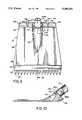
- FIG. 1shows a side elevational view of a prior art device in its initial stage of use.
- FIG. 2shows a side elevational view of the prior art device during one final stage of use.
- FIG. 3shows a side elevational view of the prior art device during an alternate final stage of use.
- FIG. 4shows a top plan view of a first embodiment of the present invention.
- FIG. 5Ais a partial cross-sectional view of one variation of the first embodiment taken along line 5--5 in FIG. 4.
- FIG. 5Bis a cross-sectional view of another variation of the first embodiment taken along line 5--5 in FIG. 4.
- FIG. 6is a bottom plan view of the first embodiment of the present invention.
- FIG. 7is a partial cross-sectional view of the first embodiment during a forward stroke of the present invention in use.
- FIG. 8is a partial cross-sectional view of the first embodiment during a backward stroke of the present invention in use.
- FIG. 9is a top plan view of a second embodiment of the present invention.
- FIG. 10is a cross-sectional view of the second embodiment taken along line 10--10 in FIG. 9.
- a first embodiment of the present inventionis seen to have a hollow handle portion 112 and a blade portion 114. It is important to note at the outset that, after prolonged use resulting in excessive wear, the blade portion may be replaced by a new one ordered from the manufacturer.
- This blade portion 114has a front edge 130 along which there is aligned a first plurality of teeth 124 which are downwardly tapered away from the front edge 130.
- the blade portion 114also has a rear edge 140 along which there is aligned a second plurality of teeth 144 which are upwardly turned away from the rear edge 140.
- the blade portion 114has a flat central plate 135.
- This mound 150has a protruding stem 152 over which a bottom end of the hollow handle portion 112 is slipped.
- the mound 150also has a shoulder 154 against which the same bottom end of the hollow handle portion 112 abuts.
- FIGS. 5A and 5Bare cross-sectional views taken along line 5--5 in FIG. 4.
- FIG. 5Athere are seen the hollow handle portion 112 and the blade portion 114 which are attached together by either a flexible metal spring pin 151 or a so-called "cotter” pin (not shown) which is passed through a bore 153 previously drilled through walls of the hollow handle portion 112, and the stem 152 on the mound 150. Removal of the spring pin 157 allows a user to replace a worn blade portion 114 quickly and easily.
- FIG. 5Bthere are seen the hollow handle portion 112 and the blade portion 114 which are attached together at the shoulder 154 by a bead 156 of welded metal that totally encircles the bottom end of the hollow handle portion 112.
- the stem 152 on the mound 150also protrudes into the bottom end of the hollow handle portion 112.
- the plurality of second teeth 144turn upwardly at the rear edge 140 of the blade portion 114.
- the plurality of first teeth 124taper downwardly away from the front edge 130 of the blade portion 114.
- the flat central plate 135 of the blade portion 114has a step 136 which leads to a slightly elevated landing section 138.
- On an underside of the landing section 138there is cut a plurality of slots 132 of which only one is illustrated in cross-section in FIG. 5. Each slot 132 extends rearwardly from the front edge 130 of the blade portion 114.
- FIG. 6shows a bottom plan view of the blade portion 114 with its flat central plate 135, its front edge 130 along which the first plurality of teeth 124 is aligned, and its rear edge 140 along which the second plurality of teeth 144 is aligned.
- the plurality of slots 132is clearly shown. In a selected end slot 132A, there is seen the nail N with its head H and its stub T caught therein.
- the slots 132are sized and cut so that each one is capable of receiving the stub T of the conventional roofing nail N.
- FIG. 7a worker pushes the hand tool forward in a direction F along a top surface of the roof R.
- the head H of the nail Nis engaged and the stub T of the nail N is pulled out of a hole 0 into which the nail N had been driven many years prior thereto.
- the nail NBecause of the existence of the slot 132A, the nail N has its stress relieved as it is extracted from the hole 0 in the roof R.
- the nails Ndo not have either their heads H snapped off or their stubs T contorted in the manner shown by the prior art devices in FIGS. 2 and 3. With the nail N remaining intact, the shingle S being removed slides smoothly over the landing section 138, the step 136, and the flat central plate 135 of the blade portion 114.
- FIG. 8shows what happens in the event that one of the many nails N in the roof R is missed on the forward stroke of the worker. However, note that the shingle S is still ripped away from its position of securement on the top surface of the roof R underneath the head H of the nail N. On the return stroke in a direction D, the worker tilts the handle portion 112 so that the blade portion 114 is raised at an angle to the roof R in order to allow the second plurality of rear teeth 144 to move smoothly across the top surface of the roof R. Because the second teeth 144 on the rear edge 140 are tapered slightly, the head H of any nail N remaining in any hole 0 is engaged from its underside.
- the head His not snapped off and the stub T is not contorted because the nail N is immediately stressed relieved due to the angle at which the blade portion 114 is tilted upwardly away from the top surface of the roof R. Furthermore, since the shingle S has already been ripped away, there is a small space left between the underside of the head H of the nail N and the top surface of the roof R. Due to the existence of this small space, the second teeth 144 along the rear edge 140 are capable of removing nails N with their heads H intact, nails N without heads H but with straight stubs T, and nails N without heads H but with contorted stubs T.
- FIG. 9there is shown a second embodiment of the present invention.
- This second embodimenthas two features differentiating it from the first embodiment shown in FIGS. 4-8.
- the second embodiment of FIG. 9has the hollow handle portion 112, the blade portion 114, the plurality of first teeth 124 on the front edge 130, the landing section 138 connected by the step 136 to the flat central plate 135, and the mound 150 having the shoulder 154 with the stem 152 protruding therefrom.
- this second embodimentinstead of securing the handle portion 112 to the mound 150 only by the single bead 156 of welded metal shown in the first embodiment in FIG. 5, this second embodiment has at least one and preferably two dimples 158A and 158B cut into sides of the stem 152.
- the heated metal of the handle portion 112melts and fills the space of the selected side dimple 158A or 158B.
- the melted metal of the handle portion 112quickly solidifies to form a tight bond with the stem 152 on the metal mound 150.
- both side dimples 158A and 158Bare filled with melted metal from the handle portion 112, there results a secure multi-point attachment of the handle portion 112 to the stem 152.
- the handle 12is made of wood and can be easily splintered or broken when the worker pushes too hard.
- this multi-point attachment of the handle portion 112 to the stem 152 of the mound 150is seen as the encircling bead 156 on the shoulder 154 and also as the second side dimple 158B.
- the second feature which differentiates the second embodiment from the first embodiment of FIGS. 4-8is a plurality of tapered gaps 146 spaced between upwardly turned claws 148 aligned along the rear edge 140 of the blade portion 114. These tapered gaps 146 between the claws 148 perform for the second embodiment the same function of removing nails N on the back stroke in the direction D, as seen in FIG. 8 for the teeth 144 in the first embodiment. Although in FIG. 9 there are only two tapered gaps 146 illustrated, a third tapered gap 146 may be hidden behind the handle portion 112 in a further embodiment not shown. The rightmost tapered gap 146 of FIG. 9 is clearly seen in the partial cross-sectional view of FIG. 10. Furthermore, as best shown in FIG.
- the claws 148 separated by the tapered gaps 146 in this second embodimentcan be considered analogous to laterally elongated teeth 144 in the first embodiment of FIGS. 4-8.
- one claw 148 in the second embodimentis functionally equivalent to at least one pair of the teeth 144 in the first embodiment.
Landscapes
- Engineering & Computer Science (AREA)
- Architecture (AREA)
- Civil Engineering (AREA)
- Structural Engineering (AREA)
- Portable Nailing Machines And Staplers (AREA)
Abstract
Description
Claims (15)
Priority Applications (1)
| Application Number | Priority Date | Filing Date | Title |
|---|---|---|---|
| US08/035,625US5280676A (en) | 1993-03-23 | 1993-03-23 | Apparatus for removing shingles and nails from a roof |
Applications Claiming Priority (1)
| Application Number | Priority Date | Filing Date | Title |
|---|---|---|---|
| US08/035,625US5280676A (en) | 1993-03-23 | 1993-03-23 | Apparatus for removing shingles and nails from a roof |
Publications (1)
| Publication Number | Publication Date |
|---|---|
| US5280676Atrue US5280676A (en) | 1994-01-25 |
Family
ID=21883829
Family Applications (1)
| Application Number | Title | Priority Date | Filing Date |
|---|---|---|---|
| US08/035,625Expired - LifetimeUS5280676A (en) | 1993-03-23 | 1993-03-23 | Apparatus for removing shingles and nails from a roof |
Country Status (1)
| Country | Link |
|---|---|
| US (1) | US5280676A (en) |
Cited By (39)
| Publication number | Priority date | Publication date | Assignee | Title |
|---|---|---|---|---|
| US5496015A (en)* | 1994-11-18 | 1996-03-05 | Carmien; Joseph A. | Roofer's ripping spade |
| FR2728919A1 (en)* | 1994-12-28 | 1996-07-05 | Travaille Claude Jean | Tool for replacing small, traditional roof tiles which weigh 1kg |
| USD392867S (en) | 1996-11-12 | 1998-03-31 | Gracy Mark S | Multi-purpose wrecking jar |
| US5836222A (en)* | 1995-10-12 | 1998-11-17 | Harpell; William | Shingle removing tool |
| US5906145A (en)* | 1997-06-02 | 1999-05-25 | Shepherd; John | Roofing shovel |
| US5916102A (en)* | 1998-01-26 | 1999-06-29 | Glaazart U.S.A., Inc. | Removable tile display |
| US6029545A (en)* | 1998-08-03 | 2000-02-29 | Harpell; William | Roofing tool |
| US6070498A (en)* | 1998-09-15 | 2000-06-06 | Mislich; Jay | Shingle removing tool |
| USD426131S (en)* | 1998-10-22 | 2000-06-06 | Juan Enrique Martinez | Shingle stripping tool |
| US6098292A (en)* | 1998-03-10 | 2000-08-08 | Harpell; William | Demolition tool |
| US6125720A (en)* | 1998-10-22 | 2000-10-03 | Malco Products, Inc. | Tool for removing roofing material |
| US6128979A (en)* | 1997-06-02 | 2000-10-10 | Shepherd; John | Roofing shovel |
| USD439126S1 (en) | 1998-10-22 | 2001-03-20 | Malco Products, Inc. | Roofing material removal tool |
| US20010041524A1 (en)* | 1997-05-28 | 2001-11-15 | Marco Steiger | Material removing tool |
| US20020053261A1 (en)* | 2000-10-27 | 2002-05-09 | Garcia C. Arturo | Shingle lifting tool |
| US20040211944A1 (en)* | 2003-04-25 | 2004-10-28 | Harold Thompson | Nail pulling hammer and hammer head |
| US20050051001A1 (en)* | 2003-09-04 | 2005-03-10 | Bond William Ralph | Crowbar tool |
| US20060037199A1 (en)* | 2004-08-20 | 2006-02-23 | Alpert Alexander G | Fastener ripper |
| US7028584B1 (en) | 2004-08-13 | 2006-04-18 | Gracy Mark S | Shingle remover with replacement blade |
| US7040195B1 (en)* | 2003-02-21 | 2006-05-09 | Lackey John P | Roof rake system |
| US20060191378A1 (en)* | 2004-06-03 | 2006-08-31 | Linscott Herbert G | Roof shingle and nail remover |
| US20070051210A1 (en)* | 2005-09-06 | 2007-03-08 | William Harpell | Tool blade |
| US20070051209A1 (en)* | 2005-09-06 | 2007-03-08 | William Harpell | Roofing tool blade |
| US7252021B1 (en) | 2004-06-03 | 2007-08-07 | Herbert Garfield Linscott | Roof shingle and nail remover |
| USD591578S1 (en)* | 2008-02-25 | 2009-05-05 | William Harpell | Demolition tool |
| US20090200487A1 (en)* | 2008-02-13 | 2009-08-13 | Tyco Healthcare Group Lp | Methods of Altering Surgical Fiber |
| WO2009106097A1 (en)* | 2008-02-29 | 2009-09-03 | Proverum Ag | Scraper blade and scraper for scraping off materials from a substrate |
| US20090288848A1 (en)* | 2008-05-21 | 2009-11-26 | S.E.P.C.O. | Tined pry bar hand tool |
| US20100132515A1 (en)* | 2006-05-04 | 2010-06-03 | Shining Golden Yida Welding & Cutting Machinery Manufacture, Ltd. | Shingle Removing Tool |
| US20100224032A1 (en)* | 2009-03-05 | 2010-09-09 | William Harpell | Material removing tool |
| US20100307295A1 (en)* | 2009-06-09 | 2010-12-09 | Craig Elliott | Nail ripper |
| US20140299824A1 (en)* | 2013-04-04 | 2014-10-09 | Samuel Knox | Staple-pulling tool and a method for its use |
| USD730702S1 (en)* | 2014-05-07 | 2015-06-02 | Fam | Knife clamp |
| USD730703S1 (en)* | 2014-05-07 | 2015-06-02 | Fam | Knife holder |
| USD731259S1 (en)* | 2013-11-07 | 2015-06-09 | Fam | Knife holder |
| USD731257S1 (en)* | 2013-11-07 | 2015-06-09 | Fam | Knife holder |
| USD731258S1 (en)* | 2013-11-07 | 2015-06-09 | Fam | Knife clamp |
| USD740068S1 (en)* | 2013-11-07 | 2015-10-06 | Fam | Knife clamp |
| US20190345720A1 (en)* | 2018-05-11 | 2019-11-14 | Jason McKinney | Roofing removal tool |
Citations (12)
| Publication number | Priority date | Publication date | Assignee | Title |
|---|---|---|---|---|
| US1218145A (en)* | 1913-11-07 | 1917-03-06 | William L Whittier | Shingle-stripper. |
| US1512622A (en)* | 1924-02-04 | 1924-10-21 | Wallace & Sons Mfg Co R | Hollow-handle article |
| US2092279A (en)* | 1936-07-09 | 1937-09-07 | Frank E Jeffers | Digging implement |
| US2165991A (en)* | 1937-03-22 | 1939-07-11 | Blackinton & Co R | Art of making hollow-handle flatware |
| US2769236A (en)* | 1953-12-17 | 1956-11-06 | Phillips Andrew Thomas | Tile removing tools |
| US3818593A (en)* | 1971-05-28 | 1974-06-25 | W Oliverius | Blade for material stripping apparatus |
| US4086699A (en)* | 1975-07-07 | 1978-05-02 | Olkkola E Alfred | Roof stripping tool |
| US4203210A (en)* | 1978-10-12 | 1980-05-20 | Hadlick Paul E Jr | Shingle stripper |
| USD265791S (en) | 1979-08-22 | 1982-08-17 | Fieni Gabriel J | Shingle digger |
| US4477972A (en)* | 1982-06-14 | 1984-10-23 | Vinal Realty Trust | Tool for use in stripping shingles |
| US4565004A (en)* | 1981-12-23 | 1986-01-21 | Heinz Peter G | Stained glass window constructing tool |
| US4809436A (en)* | 1987-01-23 | 1989-03-07 | Crookston James R | Shingle stripping tool |
- 1993
- 1993-03-23USUS08/035,625patent/US5280676A/ennot_activeExpired - Lifetime
Patent Citations (12)
| Publication number | Priority date | Publication date | Assignee | Title |
|---|---|---|---|---|
| US1218145A (en)* | 1913-11-07 | 1917-03-06 | William L Whittier | Shingle-stripper. |
| US1512622A (en)* | 1924-02-04 | 1924-10-21 | Wallace & Sons Mfg Co R | Hollow-handle article |
| US2092279A (en)* | 1936-07-09 | 1937-09-07 | Frank E Jeffers | Digging implement |
| US2165991A (en)* | 1937-03-22 | 1939-07-11 | Blackinton & Co R | Art of making hollow-handle flatware |
| US2769236A (en)* | 1953-12-17 | 1956-11-06 | Phillips Andrew Thomas | Tile removing tools |
| US3818593A (en)* | 1971-05-28 | 1974-06-25 | W Oliverius | Blade for material stripping apparatus |
| US4086699A (en)* | 1975-07-07 | 1978-05-02 | Olkkola E Alfred | Roof stripping tool |
| US4203210A (en)* | 1978-10-12 | 1980-05-20 | Hadlick Paul E Jr | Shingle stripper |
| USD265791S (en) | 1979-08-22 | 1982-08-17 | Fieni Gabriel J | Shingle digger |
| US4565004A (en)* | 1981-12-23 | 1986-01-21 | Heinz Peter G | Stained glass window constructing tool |
| US4477972A (en)* | 1982-06-14 | 1984-10-23 | Vinal Realty Trust | Tool for use in stripping shingles |
| US4809436A (en)* | 1987-01-23 | 1989-03-07 | Crookston James R | Shingle stripping tool |
Cited By (47)
| Publication number | Priority date | Publication date | Assignee | Title |
|---|---|---|---|---|
| US5496015A (en)* | 1994-11-18 | 1996-03-05 | Carmien; Joseph A. | Roofer's ripping spade |
| FR2728919A1 (en)* | 1994-12-28 | 1996-07-05 | Travaille Claude Jean | Tool for replacing small, traditional roof tiles which weigh 1kg |
| US5836222A (en)* | 1995-10-12 | 1998-11-17 | Harpell; William | Shingle removing tool |
| USD392867S (en) | 1996-11-12 | 1998-03-31 | Gracy Mark S | Multi-purpose wrecking jar |
| US20010041524A1 (en)* | 1997-05-28 | 2001-11-15 | Marco Steiger | Material removing tool |
| US8568204B2 (en) | 1997-05-28 | 2013-10-29 | Maroc Gmbh | Material removing tool |
| US6128979A (en)* | 1997-06-02 | 2000-10-10 | Shepherd; John | Roofing shovel |
| US5906145A (en)* | 1997-06-02 | 1999-05-25 | Shepherd; John | Roofing shovel |
| WO2000003105A1 (en)* | 1997-06-02 | 2000-01-20 | John Shepherd | Roofing shovel |
| US5916102A (en)* | 1998-01-26 | 1999-06-29 | Glaazart U.S.A., Inc. | Removable tile display |
| US6098292A (en)* | 1998-03-10 | 2000-08-08 | Harpell; William | Demolition tool |
| US6029545A (en)* | 1998-08-03 | 2000-02-29 | Harpell; William | Roofing tool |
| US6070498A (en)* | 1998-09-15 | 2000-06-06 | Mislich; Jay | Shingle removing tool |
| USD426131S (en)* | 1998-10-22 | 2000-06-06 | Juan Enrique Martinez | Shingle stripping tool |
| US6125720A (en)* | 1998-10-22 | 2000-10-03 | Malco Products, Inc. | Tool for removing roofing material |
| USD439126S1 (en) | 1998-10-22 | 2001-03-20 | Malco Products, Inc. | Roofing material removal tool |
| US20020053261A1 (en)* | 2000-10-27 | 2002-05-09 | Garcia C. Arturo | Shingle lifting tool |
| US6792829B2 (en) | 2000-10-27 | 2004-09-21 | Arturo C. Garcia | Shingle lifting tool |
| US7040195B1 (en)* | 2003-02-21 | 2006-05-09 | Lackey John P | Roof rake system |
| US20040211944A1 (en)* | 2003-04-25 | 2004-10-28 | Harold Thompson | Nail pulling hammer and hammer head |
| US6866247B2 (en) | 2003-04-25 | 2005-03-15 | Harold Thompson | Nail pulling hammer and hammer head |
| US20050051001A1 (en)* | 2003-09-04 | 2005-03-10 | Bond William Ralph | Crowbar tool |
| US6920807B2 (en)* | 2003-09-04 | 2005-07-26 | William Ralph Bond | Crowbar tool |
| US7252021B1 (en) | 2004-06-03 | 2007-08-07 | Herbert Garfield Linscott | Roof shingle and nail remover |
| US20060191378A1 (en)* | 2004-06-03 | 2006-08-31 | Linscott Herbert G | Roof shingle and nail remover |
| US7028584B1 (en) | 2004-08-13 | 2006-04-18 | Gracy Mark S | Shingle remover with replacement blade |
| US20060037199A1 (en)* | 2004-08-20 | 2006-02-23 | Alpert Alexander G | Fastener ripper |
| US20070051210A1 (en)* | 2005-09-06 | 2007-03-08 | William Harpell | Tool blade |
| US20070051209A1 (en)* | 2005-09-06 | 2007-03-08 | William Harpell | Roofing tool blade |
| US20100132515A1 (en)* | 2006-05-04 | 2010-06-03 | Shining Golden Yida Welding & Cutting Machinery Manufacture, Ltd. | Shingle Removing Tool |
| US8079290B2 (en)* | 2006-05-04 | 2011-12-20 | Shining Golden Yida Welding & Cutting Machinery Manufacture, Ltd. | Shingle removing tool |
| US20090200487A1 (en)* | 2008-02-13 | 2009-08-13 | Tyco Healthcare Group Lp | Methods of Altering Surgical Fiber |
| USD591578S1 (en)* | 2008-02-25 | 2009-05-05 | William Harpell | Demolition tool |
| US20110000045A1 (en)* | 2008-02-29 | 2011-01-06 | Proverum Ag | Scraper blade and scraper for scraping off materials from a substrate |
| WO2009106097A1 (en)* | 2008-02-29 | 2009-09-03 | Proverum Ag | Scraper blade and scraper for scraping off materials from a substrate |
| US20090288848A1 (en)* | 2008-05-21 | 2009-11-26 | S.E.P.C.O. | Tined pry bar hand tool |
| US20100224032A1 (en)* | 2009-03-05 | 2010-09-09 | William Harpell | Material removing tool |
| US20100307295A1 (en)* | 2009-06-09 | 2010-12-09 | Craig Elliott | Nail ripper |
| US8146460B2 (en) | 2009-06-09 | 2012-04-03 | Craig Elliott Holdings Ltd. | Nail ripper |
| US20140299824A1 (en)* | 2013-04-04 | 2014-10-09 | Samuel Knox | Staple-pulling tool and a method for its use |
| USD731259S1 (en)* | 2013-11-07 | 2015-06-09 | Fam | Knife holder |
| USD731257S1 (en)* | 2013-11-07 | 2015-06-09 | Fam | Knife holder |
| USD731258S1 (en)* | 2013-11-07 | 2015-06-09 | Fam | Knife clamp |
| USD740068S1 (en)* | 2013-11-07 | 2015-10-06 | Fam | Knife clamp |
| USD730702S1 (en)* | 2014-05-07 | 2015-06-02 | Fam | Knife clamp |
| USD730703S1 (en)* | 2014-05-07 | 2015-06-02 | Fam | Knife holder |
| US20190345720A1 (en)* | 2018-05-11 | 2019-11-14 | Jason McKinney | Roofing removal tool |
Similar Documents
| Publication | Publication Date | Title |
|---|---|---|
| US5280676A (en) | Apparatus for removing shingles and nails from a roof | |
| US4203210A (en) | Shingle stripper | |
| US20050062026A1 (en) | Roofers tool | |
| US3987827A (en) | Shingle removing tool | |
| US4458415A (en) | Hammer driven chopper | |
| US4086699A (en) | Roof stripping tool | |
| US4477972A (en) | Tool for use in stripping shingles | |
| US4470440A (en) | Impact producing tool | |
| US4858503A (en) | Shingle removing apparatus | |
| US6502646B2 (en) | Golf green repair apparatus and method | |
| US20010039738A1 (en) | Plunge drywall saw | |
| US5816632A (en) | Ice breaking and removal tool | |
| US4809436A (en) | Shingle stripping tool | |
| US5836222A (en) | Shingle removing tool | |
| US6338511B1 (en) | Root cutting shovel | |
| US6125720A (en) | Tool for removing roofing material | |
| JPH01105855A (en) | Roof plate stripper | |
| CA2435603C (en) | Multiple use hammer | |
| US6029545A (en) | Roofing tool | |
| US20060191378A1 (en) | Roof shingle and nail remover | |
| US7028584B1 (en) | Shingle remover with replacement blade | |
| US4805495A (en) | Bolt head reforming tool | |
| US5870794A (en) | Broom | |
| US6453774B1 (en) | Tool for removing roofing shingles | |
| RU2360787C2 (en) | Hammer and hammer head with front extractor |
Legal Events
| Date | Code | Title | Description |
|---|---|---|---|
| STPP | Information on status: patent application and granting procedure in general | Free format text:APPLICATION UNDERGOING PREEXAM PROCESSING | |
| FEPP | Fee payment procedure | Free format text:PAYOR NUMBER ASSIGNED (ORIGINAL EVENT CODE: ASPN); ENTITY STATUS OF PATENT OWNER: SMALL ENTITY | |
| CC | Certificate of correction | ||
| FPAY | Fee payment | Year of fee payment:4 | |
| FEPP | Fee payment procedure | Free format text:PAYER NUMBER DE-ASSIGNED (ORIGINAL EVENT CODE: RMPN); ENTITY STATUS OF PATENT OWNER: SMALL ENTITY Free format text:PAYOR NUMBER ASSIGNED (ORIGINAL EVENT CODE: ASPN); ENTITY STATUS OF PATENT OWNER: SMALL ENTITY | |
| FPAY | Fee payment | Year of fee payment:8 | |
| FPAY | Fee payment | Year of fee payment:12 | |
| AS | Assignment | Owner name:TONY R. SHEHA, D/B/A SHIN DIG TOOLS, PENNSYLVANIA Free format text:ASSIGNMENT OF ASSIGNORS INTEREST;ASSIGNOR:FIENI, GABRIEL J.;REEL/FRAME:017164/0725 Effective date:20051028 Owner name:SHEHA, TONY R. D/B/A SHIN DIG TOOLS, PENNSYLVANIA Free format text:ASSET PURCHASE AGREEMENT;ASSIGNOR:FIENI, GABRIEL J.;REEL/FRAME:017168/0041 Effective date:20051028 |