US5280608A - Programmable stall cycles - Google Patents
Programmable stall cyclesDownload PDFInfo
- Publication number
- US5280608A US5280608AUS07/724,379US72437991AUS5280608AUS 5280608 AUS5280608 AUS 5280608AUS 72437991 AUS72437991 AUS 72437991AUS 5280608 AUS5280608 AUS 5280608A
- Authority
- US
- United States
- Prior art keywords
- arbiter
- bus
- devices
- stall
- recited
- Prior art date
- Legal status (The legal status is an assumption and is not a legal conclusion. Google has not performed a legal analysis and makes no representation as to the accuracy of the status listed.)
- Expired - Lifetime
Links
Images


Classifications
- G—PHYSICS
- G06—COMPUTING OR CALCULATING; COUNTING
- G06F—ELECTRIC DIGITAL DATA PROCESSING
- G06F11/00—Error detection; Error correction; Monitoring
- G06F11/22—Detection or location of defective computer hardware by testing during standby operation or during idle time, e.g. start-up testing
- G06F11/24—Marginal checking or other specified testing methods not covered by G06F11/26, e.g. race tests
Definitions
- the present inventionrelates to a system and method for introducing stall cycles to an arbitration scheme for stressing the bandwidth and latency characteristics of a computing system.
- the central processing unit (“CPU”) of a computing system or input/output (“I/O") devices connected to the computing systemmay request and be granted access to, and control of, a commonly used bus, such as a system bus.
- An arbiterin turn is used to arbitrate bus requests and grant certain of those requests based on the programmed arbitration parameters.
- the CPU and I/O devicesrequire access and control of the bus for a predetermined period of time after it has requested such control. If access is not granted within the maximum latency tolerance of the device, performance degradation and a potential loss of data may occur in the computing system.
- the CPU and I/O devicesalso require that they be allowed to control the bus for a specific period of time over a given time interval. If they are not allowed this period of time, it may result in bandwidth problems which also may affect computing system operations.
- Computing system failuresmay occur because of these latency and bandwidth problems.
- the failuresoccur under peak loading conditions and are a function of the number of I/O devices competing for the bus along with the CPU, the data rates of these I/O devices, the loads on the devices, and the request rates for control of the bus by the CPU and I/O devices.
- Prior methods of performing such testingused software to attempt to create or recreate certain occurrences that caused system failures. Such testing was difficult to do because of the inability to control the interaction among various I/O devices in a deterministic manner. Therefore, large amounts of software run for a long period of time was required to create various latencies and bandwidth conditions the system would encounter in normal operations. This process of using large amounts of software to test latency and bandwidth was non-deterministic and in no way ensured that all of the desired stressing conditions were delivered to the system.
- the present inventionis a system and method that may be used for testing a computing system by stressing it by introducing "stall cycles.” These stall cycles are periods of time during which the bus is unavailable to any of the system devices that request the bus, such as the CPU and I/O devices. The frequency and duration of the stall cycles are variable and are used to stress the computing system latency an bandwidth characteristics associated with access and control of a bus in a more deterministic manner.
- the system of the present inventionmay be incorporated into a computing system that includes a central processing unit (“CPU"), a commonly used bus, such as a system bus, a system element that is connected to the commonly used bus, such as memory, I/O devices, and an arbiter that controls access to the commonly used bus.
- CPUcentral processing unit
- a commonly used bussuch as a system bus
- a system elementthat is connected to the commonly used bus
- memorysuch as memory, I/O devices
- arbiterthat controls access to the commonly used bus.
- the system of the present inventionis embodied as a logic circuit and arbiter that introduce controllable stall cycle signals to the computing system through such arbiter.
- the system of the present inventionis enhanced by a feedback grant line associated with the stall cycle signals.
- the system and method of the present inventionalso may include the use of two programmable registers that function as counters to control the duty cycle of the stall cycle signal input to the arbiter. This gives the system greater flexibility to present a number of different operating situations for stressing the computing system.
- the stall cycle signalsalso may be introduced by an external pulse generator that is plugged into the arbiter.
- This pulse generatormay be a stand-alone device or may be part of a larger diagnostic tool. In the latter case, there may be a feedback signal from the arbiter to the diagnostic tool.
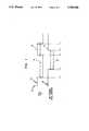
- FIG. 1shows a timing diagram of request and grant signals for the system according to the present invention, with feedback.
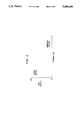
- FIG. 2shows a diagram of the stress conditions capable of being imposed on a computing system by the system of the present invention.
- FIG. 3shows a block diagram for use in discussing the preferred embodiment of the system according to the present invention.
- FIG. 4shows a block diagram for use in discussing the second embodiment of the system according to the present invention.
- FIG. 5shows a block diagram for use in discussing the third embodiment of the system according to the present invention.
- the present inventionis a system and method for introducing controllable stall cycle signals into a computing system to stress the latency and bandwidth characteristics associated with the access and control of a bus commonly used by the system CPU and I/O devices.
- the characteristics of a stall cycle signalis shown at 20.
- the period of the signalis the time it takes for a signal to complete one full cycle.
- the frequency of a signalis the inverse of the period.
- the duty cycle of a signalis the percentage of time for which the signal is in the asserted state compared with the period of the signal.
- the stall cycle periodis (a+b) or t 1 to t 5 , its frequency is 1/(a+b), and its duty cycle is [a/(a+b)] ⁇ 100%.
- FIG. 2shows the stresses that the system of the present invention may impose on a computing system by way of stall cycles. More specifically, the diagram shows the conditions under which bandwidth and latency characteristics may be tested.
- a stall cycle signalhas a high frequency and low duty cycle
- the bandwidth characteristics of the computing systemare tested. Under these conditions, it is difficult for the system devices requesting the bus to meet their bandwidth requirements because of frequent conflicts with the stall cycles.
- a stall cycle signalhas low frequency and a high duty cycle
- the latency characteristics of the computing systemare tested. Under these conditions, it is difficult for devices requesting the bus to meet their latency requirements because they will be prevented from accessing the bus for long periods of time.
- the present inventionis preferably incorporated in a computing system that includes at least a CPU, a commonly used bus, a system element connected to the commonly used bus, I/O devices, and an arbiter that arbitrates requests from the I/O devices and CPU in order to grant them access to the commonly used bus one at a time.
- the computing system incorporating the system of the present inventionis shown generally at 100.
- the computing systemcomprises CPU 102 that connects to arbiter 104 via REQUEST line 103 and GRANT line 115, logic circuit 110 via line 109, and system bus 113 via connection bus 105.
- the REQUEST line 103carries system bus request signals from the CPU to the arbiter and GRANT line 115 system bus grant signals from the arbiter to the CPU.
- Line 109handles control signals that are sent from the CPU to the logic circuit for control of the generation of stall cycle signals.
- Logic circuit 110is operable with the arbiter to form the system of the present invention that is used for generating and introducing a stall cycle signal into the computing system for controllably stressing the computing system. As shown, logic circuit 110 connects to arbiter 104 via line 111 and feedback line 114.
- the plurality of I/O devices 106connect to arbiter 104 via REQUEST lines 107 and GRANT lines 119. Each I/O device is connected to system bus 113 and memory 108 by connection bus 117.
- the CPUsends initiation signals over to logic circuit 110 which generates a predetermined stall cycle signal that is input to arbiter 104 on line 111 and the computing system then resumes its normal operation.
- Requests for the system busmay then be sent from CPU 102 and I/O device 106.
- the requests from the CPU and the I/O devicesmay be granted or delayed for a period of time. This will cause both latency and bandwidth stressing of the computing system according to the diagram in FIG. 2.
- FIG. 3shows the timing diagram 20 for the request and grant signals for the system of the present invention with feedback over feedback line 114 as shown in FIG. 3.
- the STALL REQ signal 22has a period with asserted portion "a" at 26 and de-asserted portion "b" at 24.
- the GNT (grant) signal shown at 28is asserted and de-asserted based on the STALL REQ signal at 22 and the availability of the system bus.
- the system of the present inventionincludes feedback, it is possible to accurately determine the length of the stall cycle which equals the latency system devices will experience. For example, the additional latency created by the STALL REQ signal is t 2 to t 4 . This is shown as the asserted period of the GNT signal at "c" shown at 30.
- the first embodimentmay also be configured to not include feedback line 114.
- the grant signalis not tracked. That is, the stall cycle signals are generated and sent to the arbiter but grant signal information is not tracked via a feedback line.
- the computing system incorporating a second embodiment of the system of the present inventionis shown in FIG. 4. It has CPU 402 connected to arbiter 404 via REQUEST line 403 and GRANT line 415, logic circuit 410 via line 409, and system bus 413 via connection bus 405.
- REQUEST line 403carries system bus request signals from the CPU to the arbiter and GRANT line 415 system bus grant signals from the arbiter to the CPU.
- Line 409handles control signals that are sent from the CPU to the logic circuit for control of the generation of stall cycle signals.
- Logic circuit 410connected to arbiter 404 via line 411 and feedback line 414, has two programmable registers, de-assertion register 416 and assertion register 420. These programmable registers form counters for controlling the de-assertion and assertion sections of the duty cycle of the STALL REQ. By using these two registers, it gives added flexibility to the system permitting the stressing conditions to be changed automatically under software control and eliminates the need for external test hardware.
- the plurality of I/O devices 406connect to arbiter 404 via REQUEST lines 407 and GRANT lines 419, and to system bus 413 by connection bus 417.
- the system busconnects to memory 408.
- the first activityis to program the de-assertion and assertion periods for the duty cycle of the STALL REQ signal. This is accomplished through the CPU. After this, the CPU sends the initiation signal to logic circuit 410 which causes the generation of the STALL REQ signal based on the programmed duty cycle.
- This stall cycle signalis input to arbiter 404 on line 411 and competes with the other requests for the bus. The duty cycle and frequency of the stall cycle signal determines how the computing system is stressed (see FIG. 2).
- the computing systemis operated as normal. In this operation, requests for the system bus may be sent from the CPU and I/O devices 106. Depending on the duty cycle of the stall cycle signal, the requests from the CPU and I/O devices may be granted or delayed for a period of time. This will cause both latency and bandwidth stressing of the computing system according to the diagram in FIG. 2.
- the second embodiment shown in FIG. 4includes feedback line 414.
- the second embodimentlike the first embodiment, may be configured without a feedback line.
- the third embodiment of the system of the present inventionwill be described referring to FIG. 5.
- the third embodiment of the present inventionis incorporated in the computing system shown generally at 500.
- CPU 502connects to arbiter 504 via REQUEST line 503 and GRANT line 515.
- REQUEST line 503carries system bus request signals from the CPU to the arbiter and GRANT line 515 system bus grant signals from the arbiter to the CPU.
- the CPUconnects to system bus 513 via bus connector 505.
- Pulse generator 516connects to the STALL REQ input of arbiter 504 via line 518, and generates the stall cycle signal that is used for stressing the computing system.
- FIG. 5shows feedback line 520 connected from arbiter 504 to pulse generator 516, this is meant for a situation when the pulse generator is part of a larger diagnostic tool and feedback line 520 connects to that tool. When pulse generator 516 is used alone, feedback line 520 is not used.
- the pulse generatoris connected externally to the arbiter and may have an adjustable duty cycle which will provide the advantage discussed above with regard to the second embodiment of the system of the present invention.
- the plurality of I/O devices 506connect to arbiter 504 via REQUEST lines 507 and GRANT lines 519. Each I/O device is connected to system bus 513 by connection bus 517 with bus 513 in turn connected to memory 508.
- the pulse generatoris plugged into the arbiter and the STALL REQ signals are input to the arbiter.
- the STALL REQ signalimposes stress on the computing system in an attempt to identify latency and bandwidth problems.
- the CPU and I/O devices 106provide system bus requests to the arbiter.
- the arbiterwill grant or delay for a period of time the system bus requests from the CPU and I/O devices. This will cause both latency and bandwidth stressing of the computing system in accordance with the diagram in FIG. 1.
Landscapes
- Engineering & Computer Science (AREA)
- General Engineering & Computer Science (AREA)
- Theoretical Computer Science (AREA)
- Computer Hardware Design (AREA)
- Quality & Reliability (AREA)
- Physics & Mathematics (AREA)
- General Physics & Mathematics (AREA)
- Bus Control (AREA)
Abstract
Description
Claims (13)
Priority Applications (1)
| Application Number | Priority Date | Filing Date | Title |
|---|---|---|---|
| US07/724,379US5280608A (en) | 1991-06-28 | 1991-06-28 | Programmable stall cycles |
Applications Claiming Priority (1)
| Application Number | Priority Date | Filing Date | Title |
|---|---|---|---|
| US07/724,379US5280608A (en) | 1991-06-28 | 1991-06-28 | Programmable stall cycles |
Publications (1)
| Publication Number | Publication Date |
|---|---|
| US5280608Atrue US5280608A (en) | 1994-01-18 |
Family
ID=24910201
Family Applications (1)
| Application Number | Title | Priority Date | Filing Date |
|---|---|---|---|
| US07/724,379Expired - LifetimeUS5280608A (en) | 1991-06-28 | 1991-06-28 | Programmable stall cycles |
Country Status (1)
| Country | Link |
|---|---|
| US (1) | US5280608A (en) |
Cited By (4)
| Publication number | Priority date | Publication date | Assignee | Title |
|---|---|---|---|---|
| US20050177689A1 (en)* | 2002-05-24 | 2005-08-11 | Koninklijke Philips Electronics N.V. | Programmed access latency in mock multiport memory |
| US20100138839A1 (en)* | 2007-03-28 | 2010-06-03 | Nxp, B.V. | Multiprocessing system and method |
| US8307139B1 (en)* | 2003-03-14 | 2012-11-06 | Marvell International Ltd. | Method and apparatus for dynamically granting access of a shared resource among a plurality of requestors |
| US20150261704A1 (en)* | 2014-03-17 | 2015-09-17 | Joseph S. Vaccaro | Devices with arbitrated interface busses, and methods of their operation |
Citations (9)
| Publication number | Priority date | Publication date | Assignee | Title |
|---|---|---|---|---|
| US4462072A (en)* | 1981-04-03 | 1984-07-24 | Honeywell Information Systems Inc. | Clock system having a stall capability to enable processing of errors |
| US4564943A (en)* | 1983-07-05 | 1986-01-14 | International Business Machines | System path stressing |
| US4611320A (en)* | 1984-05-21 | 1986-09-09 | Siemens Corporate Research And Support, Inc. | Programmable testing analyzer |
| US4669079A (en)* | 1984-10-31 | 1987-05-26 | International Business Machines Corporation | Method and apparatus for bus arbitration in a data processing system |
| US4965717A (en)* | 1988-12-09 | 1990-10-23 | Tandem Computers Incorporated | Multiple processor system having shared memory with private-write capability |
| US5005172A (en)* | 1988-03-18 | 1991-04-02 | Fujitsu Limited | Diagnostic system in a data processing system |
| US5067071A (en)* | 1985-02-27 | 1991-11-19 | Encore Computer Corporation | Multiprocessor computer system employing a plurality of tightly coupled processors with interrupt vector bus |
| US5239651A (en)* | 1991-12-30 | 1993-08-24 | Sun Microsystems, Inc. | Method of and apparatus for arbitration based on the availability of resources |
| US5241632A (en)* | 1992-01-30 | 1993-08-31 | Digital Equipment Corporation | Programmable priority arbiter |
- 1991
- 1991-06-28USUS07/724,379patent/US5280608A/ennot_activeExpired - Lifetime
Patent Citations (10)
| Publication number | Priority date | Publication date | Assignee | Title |
|---|---|---|---|---|
| US4462072A (en)* | 1981-04-03 | 1984-07-24 | Honeywell Information Systems Inc. | Clock system having a stall capability to enable processing of errors |
| US4564943A (en)* | 1983-07-05 | 1986-01-14 | International Business Machines | System path stressing |
| US4611320A (en)* | 1984-05-21 | 1986-09-09 | Siemens Corporate Research And Support, Inc. | Programmable testing analyzer |
| US4669079A (en)* | 1984-10-31 | 1987-05-26 | International Business Machines Corporation | Method and apparatus for bus arbitration in a data processing system |
| US5067071A (en)* | 1985-02-27 | 1991-11-19 | Encore Computer Corporation | Multiprocessor computer system employing a plurality of tightly coupled processors with interrupt vector bus |
| US5005172A (en)* | 1988-03-18 | 1991-04-02 | Fujitsu Limited | Diagnostic system in a data processing system |
| US4965717A (en)* | 1988-12-09 | 1990-10-23 | Tandem Computers Incorporated | Multiple processor system having shared memory with private-write capability |
| US4965717B1 (en)* | 1988-12-09 | 1993-05-25 | Tandem Computers Inc | |
| US5239651A (en)* | 1991-12-30 | 1993-08-24 | Sun Microsystems, Inc. | Method of and apparatus for arbitration based on the availability of resources |
| US5241632A (en)* | 1992-01-30 | 1993-08-31 | Digital Equipment Corporation | Programmable priority arbiter |
Cited By (8)
| Publication number | Priority date | Publication date | Assignee | Title |
|---|---|---|---|---|
| US20050177689A1 (en)* | 2002-05-24 | 2005-08-11 | Koninklijke Philips Electronics N.V. | Programmed access latency in mock multiport memory |
| US7231478B2 (en)* | 2002-05-24 | 2007-06-12 | Koninklijke Philips Electronics N.V. | Programmed access latency in mock multiport memory |
| US8307139B1 (en)* | 2003-03-14 | 2012-11-06 | Marvell International Ltd. | Method and apparatus for dynamically granting access of a shared resource among a plurality of requestors |
| US9037767B1 (en) | 2003-03-14 | 2015-05-19 | Marvell International Ltd. | Method and apparatus for dynamically granting access of a shared resource among a plurality of requestors |
| US20100138839A1 (en)* | 2007-03-28 | 2010-06-03 | Nxp, B.V. | Multiprocessing system and method |
| US8918786B2 (en)* | 2007-03-28 | 2014-12-23 | Nxp, B.V. | Generating simulated stall signals based on access speed model or history of requests independent of actual processing or handling of conflicting requests |
| US20150261704A1 (en)* | 2014-03-17 | 2015-09-17 | Joseph S. Vaccaro | Devices with arbitrated interface busses, and methods of their operation |
| US9563590B2 (en)* | 2014-03-17 | 2017-02-07 | Nxp Usa, Inc. | Devices with arbitrated interface busses, and methods of their operation |
Similar Documents
| Publication | Publication Date | Title |
|---|---|---|
| EP0343770B1 (en) | Multi-bus microcomputer system with bus arbitration | |
| EP0378070B1 (en) | Method and apparatus for limiting the utilization of an asynchronous bus with distributed controlled access | |
| US5506972A (en) | Computer system having dynamically programmable linear/fairness priority arbitration scheme | |
| US5280591A (en) | Centralized backplane bus arbiter for multiprocessor systems | |
| DE69721393T2 (en) | Switching a system host computer | |
| EP0216533B1 (en) | Computer-based instrument system | |
| US5740380A (en) | Method and system for apportioning computer bus bandwidth | |
| US5301282A (en) | Controlling bus allocation using arbitration hold | |
| CA1306068C (en) | Apparatus and method for servicing interrupts utilizing a pended bus | |
| US5420985A (en) | Bus arbiter system and method utilizing hardware and software which is capable of operation in distributed mode or central mode | |
| JP3583183B2 (en) | Data processing device | |
| WO1996017302A1 (en) | Bridge between two buses | |
| EP0150767A2 (en) | Program controlled bus arbitration for a distributed array processing system | |
| US6122693A (en) | PCI bus utilization diagnostic monitor | |
| US4612542A (en) | Apparatus for arbitrating between a plurality of requestor elements | |
| US5596749A (en) | Arbitration request sequencer | |
| US5748916A (en) | VXIbus device which intelligently monitors bus conditions and begins early cycles for improved performance | |
| US5822549A (en) | Computer system and bus controller for controlling access to a computer bus | |
| US5241661A (en) | DMA access arbitration device in which CPU can arbitrate on behalf of attachment having no arbiter | |
| US5280608A (en) | Programmable stall cycles | |
| US5767701A (en) | Synchronous contention prevention logic for bi-directional signals | |
| US7765349B1 (en) | Apparatus and method for arbitrating heterogeneous agents in on-chip busses | |
| US6507808B1 (en) | Hardware logic verification data transfer checking apparatus and method therefor | |
| US7231479B2 (en) | Round robin selection logic improves area efficiency and circuit speed | |
| US6523075B1 (en) | Method and system for controlling internal busses to prevent busses contention during internal scan testing by using a centralized control resource |
Legal Events
| Date | Code | Title | Description |
|---|---|---|---|
| AS | Assignment | Owner name:DIGITAL EQUIPMENT CORPORATION, MASSACHUSETTS Free format text:ASSIGNMENT OF ASSIGNORS INTEREST.;ASSIGNORS:BEAVERSON, AUTHUR J.;HUNT, THOMAS E.;LIDINGTON, GARY P.;REEL/FRAME:005818/0662;SIGNING DATES FROM 19910808 TO 19910814 | |
| STCF | Information on status: patent grant | Free format text:PATENTED CASE | |
| FPAY | Fee payment | Year of fee payment:4 | |
| FPAY | Fee payment | Year of fee payment:8 | |
| AS | Assignment | Owner name:COMPAQ INFORMATION TECHNOLOGIES GROUP, L.P., TEXAS Free format text:ASSIGNMENT OF ASSIGNORS INTEREST;ASSIGNORS:DIGITAL EQUIPMENT CORPORATION;COMPAQ COMPUTER CORPORATION;REEL/FRAME:012447/0903;SIGNING DATES FROM 19991209 TO 20010620 | |
| AS | Assignment | Owner name:HEWLETT-PACKARD DEVELOPMENT COMPANY, L.P., TEXAS Free format text:CHANGE OF NAME;ASSIGNOR:COMPAQ INFORMATION TECHNOLOGIES GROUP, LP;REEL/FRAME:015000/0305 Effective date:20021001 | |
| FPAY | Fee payment | Year of fee payment:12 |