US5279723A - Filtered cathodic arc source - Google Patents
Filtered cathodic arc sourceDownload PDFInfo
- Publication number
- US5279723A US5279723AUS07/921,780US92178092AUS5279723AUS 5279723 AUS5279723 AUS 5279723AUS 92178092 AUS92178092 AUS 92178092AUS 5279723 AUS5279723 AUS 5279723A
- Authority
- US
- United States
- Prior art keywords
- housing
- cathode
- anode
- ion source
- section
- Prior art date
- Legal status (The legal status is an assumption and is not a legal conclusion. Google has not performed a legal analysis and makes no representation as to the accuracy of the status listed.)
- Expired - Lifetime
Links
Images

Classifications
- H—ELECTRICITY
- H01—ELECTRIC ELEMENTS
- H01J—ELECTRIC DISCHARGE TUBES OR DISCHARGE LAMPS
- H01J27/00—Ion beam tubes
- H01J27/02—Ion sources; Ion guns
- H01J27/022—Details
- C—CHEMISTRY; METALLURGY
- C23—COATING METALLIC MATERIAL; COATING MATERIAL WITH METALLIC MATERIAL; CHEMICAL SURFACE TREATMENT; DIFFUSION TREATMENT OF METALLIC MATERIAL; COATING BY VACUUM EVAPORATION, BY SPUTTERING, BY ION IMPLANTATION OR BY CHEMICAL VAPOUR DEPOSITION, IN GENERAL; INHIBITING CORROSION OF METALLIC MATERIAL OR INCRUSTATION IN GENERAL
- C23C—COATING METALLIC MATERIAL; COATING MATERIAL WITH METALLIC MATERIAL; SURFACE TREATMENT OF METALLIC MATERIAL BY DIFFUSION INTO THE SURFACE, BY CHEMICAL CONVERSION OR SUBSTITUTION; COATING BY VACUUM EVAPORATION, BY SPUTTERING, BY ION IMPLANTATION OR BY CHEMICAL VAPOUR DEPOSITION, IN GENERAL
- C23C14/00—Coating by vacuum evaporation, by sputtering or by ion implantation of the coating forming material
- C23C14/22—Coating by vacuum evaporation, by sputtering or by ion implantation of the coating forming material characterised by the process of coating
- C23C14/221—Ion beam deposition
- H—ELECTRICITY
- H01—ELECTRIC ELEMENTS
- H01J—ELECTRIC DISCHARGE TUBES OR DISCHARGE LAMPS
- H01J27/00—Ion beam tubes
- H01J27/02—Ion sources; Ion guns
- H01J27/08—Ion sources; Ion guns using arc discharge
- H01J27/14—Other arc discharge ion sources using an applied magnetic field
- H—ELECTRICITY
- H01—ELECTRIC ELEMENTS
- H01J—ELECTRIC DISCHARGE TUBES OR DISCHARGE LAMPS
- H01J2237/00—Discharge tubes exposing object to beam, e.g. for analysis treatment, etching, imaging
- H01J2237/02—Details
- H01J2237/022—Avoiding or removing foreign or contaminating particles, debris or deposits on sample or tube
- H—ELECTRICITY
- H01—ELECTRIC ELEMENTS
- H01J—ELECTRIC DISCHARGE TUBES OR DISCHARGE LAMPS
- H01J2237/00—Discharge tubes exposing object to beam, e.g. for analysis treatment, etching, imaging
- H01J2237/30—Electron or ion beam tubes for processing objects
- H01J2237/31—Processing objects on a macro-scale
- H01J2237/3142—Ion plating
Definitions
- the present inventionis directed to an ion source, particular to an ion source using a cathodic vacuum arc, and more particularly to an ion source using a filtered cathodic arc for the production of dense, adherent coatings, wherein the filtering eliminates or reduces macro-particles normally produced by the cathodic arc.
- PVDphysical vapor deposition
- Ion-based coating methodshave the potential to produce superior coatings due to the ability to control the arrival energy of the ions.
- Ion sources involving vacuum arc-based processesoffer the prospect for overcoming the difficulties relative to the PVD techniques by making use of their ability to provide copious quantities of ions of virtually any conductive material.
- Vacuum arc coating techniquesgenerally involve use of either an anodic arc or a cathodic arc, with the cathode arc technique being of either a pulsed or continuous type.
- the present inventionfulfills the prior need by providing an ion source using the cathodic vacuum arc for producing large currents of positive ions of a wide variety of materials, wherein the ions produce coatings with improved properties such as high density and adhesion, while the coatings are essentially free of blemishes caused by macro-particles, the macro-particles having been filtered out.
- An object of the present inventionis to provide an ion source using a cathodic vacuum arc.
- a further object of the inventionis to provide a cathodic vacuum arc for producing a highly ionized metal vapor for dense, adherent coatings.
- a further object of the inventionis to provide a filtered cathodic arc ion source using a bent magnetic field for eliminating macro-particles.
- a still further object of the inventionis to provide an ion source using a cathodic vacuum arc and means for filtering out macro-particles produced by the cathodic arc.
- Another object of the inventionis to provide a cathodic arc ion source which confines the arc to the end of a frustum-shaped cathode (target) which increases utilization of the target material.
- Another object of the inventionis to provide a cathodic arc ion source coupled to a macro-particle filter.
- Another object of the inventionis to provide a macro-particle filter for a cathodic arc ion source which uses a bent magnetic field and which consists of a plurality of straight solenoids, end to end, but placed at 45° to one another.
- Another object of the inventionis to provide a filtered cathodic arc ion source which uses a cathode (target) having tapered sides and a forty-five degree macro-particle filter, which utilizes a series of baffles for trapping macro-particles.
- the present inventioncomprises a cathodic arc ion source coupled to a macro-particle filter using a bent magnetic field to guide the ions from the target to a point of use.
- the ion sourceutilizes a frustum-shaped cathode (target) which confines the arc to the end of the target, whereby the arc spot moves randomly and provides for good utilization of the target material.
- the macro-particle filterconsists of two straight solenoids placed end-to-end, but at 45° to one another. This prevents line-of-sight from the arc spot on the target to the parts to be coated, yet provides a path for ions and electrons to flow.
- the filteralso includes a plurality of baffles attached to the inner wall to trap the macro-particles and prevent the macro-particles from bouncing off the walls of the vacuum chamber and reaching the parts to be coated.
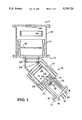
- FIG. 1is a schematic illustration of an embodiment of the filtered ion source made in accordance with the present invention
- FIG. 2is a diagram illustrating ion current increase relative to increasing magnetic field produced by increased current in the coils.
- FIG. 3is a diagram illustrating measured current with increasing chamber pressure.
- the present inventionis directed to a filtered cathodic arc ion source which is particularly applicable for coating small parts, and utilizes a bent magnetic field to guide the metal ions from the target to the part to be coated, while preventing macro-particles from hitting the part to be coated.
- the bent magnetic fieldis produced by two solenoids, placed end-to-end, but bent at a 45 degree angle.
- the two straight sectionsreplace the prior known 90 degree angle toroidal system; and tests have shown the straight solenoids with a 45° bend have higher transmission than curved sections.
- bafflesare used to trap the macro-particles; and tests have shown that the baffles reduce the number of macro-particles reaching the part to be coated to near zero.
- the filtered ion sourceconsists basically of a cathodic arc source coupled to a macro-particle filter.
- the arc sourceitself is constructed mainly of off-the-shelf vacuum components, and utilizes an axial magnetic field and a standard 15 cc E-beam evaporation charge brazed to a water-cooled target holder.
- the target or cathodeis of a frustum-shape and due to the tapered sides of the target, the arc is confined to the end thereof for increased target material utilization.
- the arctends to drift in the direction of the acute angle (15°) formed between the target surface and the magnetic field. This pushes the arc to the end of the target.
- the arc spotmoves randomly, eroding the target surface in such a way that it forms a surface normal to the magnetic field lines.
- the arcmoves preferentially to the high spots on the target surface, ensuring even target erosion and good utilization of target material.
- Target material utilization of over 65%has been demonstrated by this source.
- target materials with inherently low spot mobilitysuch as a 15 cc graphite target, have been run in the present source for over an hour at 100 amps.
- the filtered ion source of the present inventionalso utilizes placement of a secondary or auxiliary anode near the part to be coated (substrate), and is adapted for introducing reactive gases near the substrate, which allows the source to run reliably during reactive depositions.
- the metal coating rate on the primary anode, located close to the arc target (cathode),is sufficiently high to avoid problems with insulating layers forming and interfering with the flow of arc current. Ions are electrostatically repelled from the secondary or auxiliary anode located at the exit of the filter, so its coating rate is low and requires only periodic cleaning.
- the flow of electrons through the macro-particle filter to the secondary anodegenerates the potentials and produces the electrostatic field required to guide the ions around the 45° bend in the filter.
- the magnetic field strengths in the two straight solenoidsare variable and not strong enough to influence the ion trajectories directly, but a 50-200 G field constrains the electrons strongly.
- Limiting cross-field motion of the electronsallows an electrostatic potential to build in the system, which in turn, guides the ions. Any cross-field conducting surfaces will reduce the potentials produced, and reduce the ion transport efficiency through the filter.
- the magnetic field lines of the present sourceare nearly parallel to the walls of the vacuum chamber, and the field lines terminate at the annular anodes located at both ends of the filter, with an electrically floating ring surrounding the cathode (arc target).
- the magnetic fieldis substantially continuous from the cathode through the filter, which has been shown to give up to 80% ion transmission in straight, solenoidal systems.
- the source of this inventiontakes advantage of this by using two straight sections bent at 45° rather than the previously known 90° toroidal section. While the source of this invention has not been optimized, it delivers over 3 A of ions at the end of the filter out of 10 A produced at the arc and a peak coating rate over 0.8 ⁇ m/min. of titanium nitride for an arc current of 100 A.
- baffles made of non-magnetic materialare positioned in the location that would lead to a single-bounce path from target to substrate.
- the bafflesare positioned so bounce trajectories would hit the chamber walls, or preferably head back toward the target.
- the effectiveness of the baffleshas been clearly shown by tests where the macro-particle density dropped a hundredfold with addition of baffles in the bent-tube section of the source. Tests showed that the remaining macro-particles typically number less than 0.2 particle/cm 2 /min. of coating time for most materials at 100 A of arc current, and optimizing of the baffling should eliminate any remaining areas that have a single-bounce path to the substrate.
- the ion source of this inventionhas been shown to operate reliably for many tens of minutes at a time, and can use target materials efficiently, even difficult materials such as graphite. It has been shown that ion transport through the filter is improved by adding an anode at the exit of the macro-particle filter and carrying a portion of the arc current through the filter. This current also ionizes any background gas in the chamber, and may improve reactive coatings.
- the ions exiting the macro-particle filter in the embodiment testedare concentrated in a beam of about 2 inches in diameter, using a source having an inside wall diameter of 6 inches, with the baffles reducing the source diameter to 4.5 inches, and thus are effective for coating small parts.
- a source having an inside wall diameter of 6 incheswith the baffles reducing the source diameter to 4.5 inches, and thus are effective for coating small parts.
- the ion beamcan be rastered easily with externally applied magnetic fields on the order of 10 G, which fields are not strong enough to modify the ion trajectories directly. This is a further confirmation of the flux-tube model upon which the macro-particle filter is based.
- FIG. 1schematically illustrates an embodiment of the invention utilizing a bent magnetic field which takes the advantages provided by utilizing straight solenoidal sections.
- a cathodic arc ion source generally indicated at 10is connected to a vacuum chamber generally indicated at 11 via a hollow interconnect or coupling assembly 12.
- the ion source 10comprises a housing 13 forming a chamber therein and within which is positioned a water-cooled anode assembly 14 and a water-cooled cathode (target material) assembly generally indicated at 15.
- the assemblies 14 and 15are retained in housing 13 via a flange 16 and end plate 17. Extending through end plate 17 are coolant lines 18 for the anode assembly 14 and coolant lines 19 for the cathode or target assembly 15.
- the cathode assembly 15contains a cathode 20 which may be of a standard type, known as an E-beam muffin, which may be composed of copper, titanium, graphite, or other conductive metal, and having tapered or sloped sides 21, and a magnet 22 positioned behind (below) cathode 20.
- An arc starter 23is positioned in spaced relation to cathode 20. If desired, magnet 22 may be omitted for certain applications.
- electrical power supply leads or linesconnect assemblies 14 and 15 with appropriate external power sources and a control mechanism, not shown.
- Anode assembly 14includes an annular hollow anode 25 having tapering or sloping sides 26.
- a solenoidal coil 27extends around the exterior of housing 13 and is connected to a power supply, not shown.
- Housing 13 of ion source 10is connected to a housing extension 28 connected at a 45° angle, with housing extension 28 being connected to vacuum chamber 11 via coupling assembly 12.
- housing extension 28Positioned within housing 13 and extension 28 are a plurality of spaced baffles 29, which consist of annular rings made of non-magnetic material, such as stainless steel sheeting. The number, spacing, and location of the baffles 29 depend on the single-bounce pattern of macro-particles from the arc target or cathode 20, so as to prevent macro-particles from reaching parts to be coated, indicated at 30 located at the exit end of vacuum chamber 11 as shown.
- Vacuum chamber 11is provided with means for drawing a vacuum, not shown, but known in the art, and provided with an internally located cylindrical coil 31, an annular baffle 32, and an auxiliary or secondary anode 33, each operatively connected to and/or supported by a wall 34 of vacuum chamber 11.
- Coil 31 and auxiliary anode 33are connected to appropriate electrical power supplies, not shown.
- Baffle 32is constructed of non-magnetic material as are baffles 29. While the coil 31 is illustrated as being mounted within wall 34 of vacuum chamber 11, such is due to the geometry of the existing vacuum chamber. It is not a requirement that coil 31 be inside wall 34, only that it produces a solenoidal B-field. In fact, construction may be simpler if the coil is mounted externally of wall 34.
- the magnetic field produced by coil 27 around anode and cathode assemblies 14 and 15, and the 15° slope on the side 21 of cathode 20confines the arc spot to the end of the cathode 20.
- the spotmoves randomly over the end surface, and uniformly erodes the cathode 20.
- the arc spotpreferentially moves to the high spots on the target or cathode, eroding them back to level (defined as a surface normal to the magnetic field lines at the cathode). This leads to nearly complete utilization of the material of target or cathode 20.
- the macro-particle filterconsists of two straight solenoids (coils 27 and 31) placed end-to-end, but positioned at 45° to each other. This prevents line-of-sight from the arc spot on target 20 to the parts to be coated, indicated at 30, yet provides a path for ions and electrons to flow.
- the filterincludes the baffles 29 and baffle 32 which function to prevent macro-particles particles produced in target 20 from bouncing off the walls 13 and 34 and reaching the part 32 to be coated. These baffles are positioned so the first bounce reflects the particle back toward the target 20, or traps the particle, thereby preventing same from passing with the ions to parts 30 to be coated.
- the magnetic field linesare nearly parallel to the walls 13 and 34 of the ion source 10 and vacuum chamber 11, and terminate at annular anodes 25 and 33 at both ends of the filter, with anode 25 surrounding the cathode or target 20.
- the magnetic fieldis substantially continuous from the cathode 20 through the coil 31 and anode 32 by using two straight sections 27 and 31 bent at 45°, which has been shown to give up to 80% ion transmission in straight, solenoidal systems, and tests have shown the bent-magnetic field arrangement of FIG. 1 delivers over 3 A of ions and a peak coating rate of over 0.8 ⁇ m/min. of titanium nitride for an arc current of 100 A.
- the apparatus of FIG. 1was operated with and without the secondary or auxiliary anode 33, located at the exit of the filter and connected to the arc-power supply.
- the current in the field coils 27 and 31was varied, and the current to a biased plate was measured, with and without the anode 33 connected.
- the first plotshows the increase in measured current when the anode was connected.
- the measured currentincreased by nearly 80% for the higher magnetic field cases (coil current increased).
- the pressure of vacuum chamber 11was held at 0.15 mTorr of argon to stabilize the arc.
- the ion currentwas measured as the chamber pressure was varied, both with and without the anode 33 connected. This is shown in FIG. 3.
- the increase in current at the higher pressure in the cases with the anode 33 connectedis thought to be due to argon ionized by the electrons flowing to the anode 33.
- the cases with the anode disconnectedshow no increase in current as the pressure is increased.
- those measured with the anode connectedare expected to include approximately 20% argon ions.
- the ionization of the background gasmay aid the formation of reactive coatings such as titanium nitride.
- the substrateis first cleaned in situ with a DC sputter etch in argon.
- the coil currents in the source and chamber coilswere 9.3 and 30 amperes, respectively.
- the nitrogen flow ratewas 165 sccm, with the iris valve set to 15%, giving a chamber pressure of 0.30 mTorr during the coating run and 2.88 mTorr after the run. The pressure was low during the run due to the gettering effect of the fresh titanium coating on the chamber walls.
- No argonwas introduced into the chamber during the coating run.
- the substratewas biased during the coating to 200 v.
- the arc currentwas 100 amperes, with an arc voltage of 42-43 volts.
- the coating rate under these conditionswas 2.5-8 k ⁇ per minute.
- the present inventionprovides a solution to the problem of producing blemished coatings from ion sources using a cathodic arc discharge by means of its macro-particle-filtered cathodic arc ion source for use in high-rate coating of metals and reactively produced oxide and nitrides.
- the inventionhas illustrated the flux-tube model of plasma transport and has verified that baffles can be used to protect substrates or parts to be coated from macro-particles bouncing off the vacuum chamber or ion source walls.
- the inventionprovides improved ion transmission through the macro-particle filter by utilizing an anode at the exit of the filter, and carrying a portion of the arc current through the filter, which current also ionizes any background gas in the chamber.
Landscapes
- Chemical & Material Sciences (AREA)
- Engineering & Computer Science (AREA)
- Combustion & Propulsion (AREA)
- Chemical Kinetics & Catalysis (AREA)
- Materials Engineering (AREA)
- Mechanical Engineering (AREA)
- Metallurgy (AREA)
- Organic Chemistry (AREA)
- Physical Vapour Deposition (AREA)
Abstract
Description
Claims (20)
Priority Applications (1)
| Application Number | Priority Date | Filing Date | Title |
|---|---|---|---|
| US07/921,780US5279723A (en) | 1992-07-30 | 1992-07-30 | Filtered cathodic arc source |
Applications Claiming Priority (1)
| Application Number | Priority Date | Filing Date | Title |
|---|---|---|---|
| US07/921,780US5279723A (en) | 1992-07-30 | 1992-07-30 | Filtered cathodic arc source |
Publications (1)
| Publication Number | Publication Date |
|---|---|
| US5279723Atrue US5279723A (en) | 1994-01-18 |
Family
ID=25445965
Family Applications (1)
| Application Number | Title | Priority Date | Filing Date |
|---|---|---|---|
| US07/921,780Expired - LifetimeUS5279723A (en) | 1992-07-30 | 1992-07-30 | Filtered cathodic arc source |
Country Status (1)
| Country | Link |
|---|---|
| US (1) | US5279723A (en) |
Cited By (64)
| Publication number | Priority date | Publication date | Assignee | Title |
|---|---|---|---|---|
| US5433836A (en)* | 1991-03-25 | 1995-07-18 | Commonwealth Scientific And Industrial Research Organization | Arc source macroparticle filter |
| US5435900A (en)* | 1992-11-04 | 1995-07-25 | Gorokhovsky; Vladimir I. | Apparatus for application of coatings in vacuum |
| US5441624A (en)* | 1992-08-25 | 1995-08-15 | Northeastern University | Triggered vacuum anodic arc |
| WO1995029272A1 (en)* | 1994-04-25 | 1995-11-02 | Vapor Technologies, Inc. | Rectangular vacuum-arc plasma source |
| WO1995029044A1 (en)* | 1994-04-25 | 1995-11-02 | The Gillette Company | Amorphous diamond coating of blades |
| US5468363A (en)* | 1994-04-25 | 1995-11-21 | Regents Of The University Of California | Magnetic-cusp, cathodic-arc source |
| US5518597A (en)* | 1995-03-28 | 1996-05-21 | Minnesota Mining And Manufacturing Company | Cathodic arc coating apparatus and method |
| US5580429A (en)* | 1992-08-25 | 1996-12-03 | Northeastern University | Method for the deposition and modification of thin films using a combination of vacuum arcs and plasma immersion ion implantation |
| WO1996026531A3 (en)* | 1995-02-20 | 1996-12-12 | Avimo Group Limited | Filtered cathodic arc source |
| WO1998003988A3 (en)* | 1996-07-24 | 1998-03-26 | Univ Nanyang | Cathode arc source and graphite target |
| US5738768A (en)* | 1995-10-31 | 1998-04-14 | Caterpillar Inc. | Process for reducing particle defects in arc vapor deposition coatings |
| DE19739527A1 (en)* | 1997-09-09 | 1999-03-11 | Rossendorf Forschzent | Magnetically filtered vacuum arc plasma source |
| US5908602A (en)* | 1994-11-18 | 1999-06-01 | Surfcoat Oy | Apparatus for generation of a linear arc discharge for plasma processing |
| US5932078A (en)* | 1997-08-30 | 1999-08-03 | United Technologies Corporation | Cathodic arc vapor deposition apparatus |
| WO1999022396A3 (en)* | 1997-10-24 | 1999-09-10 | Filplas Vacuum Technology Pte | Enhanced macroparticle filter and cathode arc source |
| US5972185A (en)* | 1997-08-30 | 1999-10-26 | United Technologies Corporation | Cathodic arc vapor deposition apparatus (annular cathode) |
| US5976636A (en)* | 1998-03-19 | 1999-11-02 | Industrial Technology Research Institute | Magnetic apparatus for arc ion plating |
| US5997705A (en)* | 1999-04-14 | 1999-12-07 | Vapor Technologies, Inc. | Rectangular filtered arc plasma source |
| US6009829A (en)* | 1997-08-30 | 2000-01-04 | United Technologies Corporation | Apparatus for driving the arc in a cathodic arc coater |
| US6027619A (en)* | 1996-12-19 | 2000-02-22 | Micron Technology, Inc. | Fabrication of field emission array with filtered vacuum cathodic arc deposition |
| US6036828A (en)* | 1997-08-30 | 2000-03-14 | United Technologies Corporation | Apparatus for steering the arc in a cathodic arc coater |
| US6077572A (en)* | 1997-06-18 | 2000-06-20 | Northeastern University | Method of coating edges with diamond-like carbon |
| US6100628A (en)* | 1996-09-30 | 2000-08-08 | Motorola, Inc. | Electron emissive film and method |
| US6103074A (en)* | 1998-02-14 | 2000-08-15 | Phygen, Inc. | Cathode arc vapor deposition method and apparatus |
| US6171456B1 (en)* | 1997-03-28 | 2001-01-09 | Kulicke And Soffa Industries Inc. | Method for making improved long life bonding tools |
| US6204595B1 (en) | 1995-07-10 | 2001-03-20 | The Regents Of The University Of California | Amorphous-diamond electron emitter |
| US6391164B1 (en)* | 2000-06-23 | 2002-05-21 | Isak I. Beilis | Deposition of coatings and thin films using a vacuum arc with a non-consumable hot anode |
| EP1245694A1 (en)* | 2001-03-29 | 2002-10-02 | Nissin Electric Co., Ltd. | Vacuum arc vapor deposition apparatus and vacuum arc vapor deposition method |
| US6506292B2 (en) | 2000-10-03 | 2003-01-14 | Nissin Electric Co., Ltd. | Film forming apparatus |
| US6532823B1 (en) | 1999-03-18 | 2003-03-18 | Read-Rite Corporation | Insulator layers for magnetoresistive transducers |
| US6548817B1 (en)* | 1999-03-31 | 2003-04-15 | The Regents Of The University Of California | Miniaturized cathodic arc plasma source |
| US20030085123A1 (en)* | 1995-02-20 | 2003-05-08 | Shi Xu Ian | Filtered cathode arc source deposition apparatus |
| US20030094366A1 (en)* | 2000-07-07 | 2003-05-22 | Hiroshi Inaba | Plasma processing apparatus with real-time particle filter |
| US20030155230A1 (en)* | 1997-10-24 | 2003-08-21 | Xu Shi | Enhanced macroparticle filter and cathode arc source |
| US6635156B1 (en)* | 1997-04-04 | 2003-10-21 | V.I.P.-Vacuum Ion Plasma Technologies Ltd. | Producing electric arc plasma in a curvilinear plasmaguide and substrate coating |
| WO2003087425A1 (en)* | 2002-04-10 | 2003-10-23 | Sathrum Paul E | Filtered ion source |
| US6663755B2 (en)* | 2000-04-10 | 2003-12-16 | G & H Technologies Llc | Filtered cathodic arc deposition method and apparatus |
| US20040124131A1 (en)* | 2002-09-11 | 2004-07-01 | Aitchison Bradley J. | Precursor material delivery system for atomic layer deposition |
| US20040168637A1 (en)* | 2000-04-10 | 2004-09-02 | Gorokhovsky Vladimir I. | Filtered cathodic arc deposition method and apparatus |
| US20050181238A1 (en)* | 2004-02-12 | 2005-08-18 | Seagate Technology Llc | Dual-layer carbon-based protective overcoats for recording media by filtered cathodic ARC deposition |
| US20050249983A1 (en)* | 2004-05-06 | 2005-11-10 | Seagate Technology Llc | Thickness gradient protective overcoat layers by filtered cathodic arc deposition |
| EP1609882A1 (en)* | 2004-06-24 | 2005-12-28 | METAPLAS IONON Oberflächenveredelungstechnik GmbH | Coating device and method by cathodic sputtering |
| US20070187229A1 (en)* | 2003-10-21 | 2007-08-16 | Aksenov Ivan I | Filtered cathodic-arc plasma source |
| US20070251816A1 (en)* | 2006-05-01 | 2007-11-01 | Vapor Technologies, Inc. | Bi-directional filtered arc plasma source |
| US20070278444A1 (en)* | 2002-12-18 | 2007-12-06 | Vapor Technologies, Inc. | Valve component for faucet |
| US20080066315A1 (en)* | 2006-09-15 | 2008-03-20 | The Gillette Company | Blade supports for use in shaving systems |
| WO2008101107A1 (en) | 2007-02-14 | 2008-08-21 | Proteus Biomedical, Inc. | In-body power source having high surface area electrode |
| US20080264341A1 (en)* | 2007-04-26 | 2008-10-30 | Veeco Instruments Inc. | Apparatus for cathodic vacuum-arc coating deposition |
| US20080298910A1 (en)* | 2007-03-29 | 2008-12-04 | Guehring Ohg | Droplet-free coating systems manufactured by arc-evaporation method |
| US20080315146A1 (en)* | 2002-12-18 | 2008-12-25 | Masco Corporation Of Indiana | Faucet |
| CN100447934C (en)* | 2004-11-05 | 2008-12-31 | 哈尔滨工业大学 | Vacuum cathode arc straight tube filter |
| WO2009076155A3 (en)* | 2007-12-07 | 2010-07-08 | Varian Semiconductor Equipment Associates, Inc. | Particle trap |
| US20100186834A1 (en)* | 2002-12-18 | 2010-07-29 | Masco Corporation Of Indiana | Faucet component with improved coating |
| WO2011002036A1 (en)* | 2009-07-01 | 2011-01-06 | 株式会社フェローテック | Divided annular rib-shaped plasma processing device |
| US8220489B2 (en) | 2002-12-18 | 2012-07-17 | Vapor Technologies Inc. | Faucet with wear-resistant valve component |
| CN103469166A (en)* | 2013-10-12 | 2013-12-25 | 武汉大学 | Integrated cathode arc target |
| US20150345010A1 (en)* | 2013-09-30 | 2015-12-03 | University Of Dayton | Methods of magnetically enhanced physical vapor deposition |
| US9624570B2 (en) | 2012-02-09 | 2017-04-18 | Fluxion Inc. | Compact, filtered ion source |
| US20170204507A1 (en)* | 2014-07-30 | 2017-07-20 | Kabushiki Kaisha Kobe Seiko Sho (Kobe Steel, Ltd.) | Arc evaporation source |
| EP3263737A1 (en) | 2016-06-29 | 2018-01-03 | Oerlikon Surface Solutions AG, Pfäffikon | Macroparticle filter device and method for use in cathodic arc deposition |
| CN108441826A (en)* | 2018-02-26 | 2018-08-24 | 温州职业技术学院 | A kind of gas ion source, metal ion source and electron source enhancing arc source and arc current excitation |
| US10679829B1 (en) | 2011-09-07 | 2020-06-09 | Nano-Product Engineering, LLC | Reactors and methods for making diamond coatings |
| CN111455336A (en)* | 2020-04-30 | 2020-07-28 | 苏州艾钛科纳米科技有限公司 | Electromagnetic field enhanced magnetron sputtering device and method for preparing diamond-like carbon coating |
| US20220307125A1 (en)* | 2019-07-03 | 2022-09-29 | Oerlikon Surface Solutions Ag, Pfäffikon | Cathodic arc source |
Citations (23)
| Publication number | Priority date | Publication date | Assignee | Title |
|---|---|---|---|---|
| US2724058A (en)* | 1945-08-29 | 1955-11-15 | Stanley P Frankel | Calutron receivers |
| US2777958A (en)* | 1951-02-10 | 1957-01-15 | Hartford Nat Bank & Trust Co | Magnetic electron lens |
| US2906879A (en)* | 1956-07-25 | 1959-09-29 | Farrand Optical Co Inc | Imaging apparatus |
| US2972695A (en)* | 1957-05-24 | 1961-02-21 | Vickers Electrical Co Ltd | Stabilisation of low pressure d.c. arc discharges |
| US3376414A (en)* | 1965-06-04 | 1968-04-02 | Atomic Energy Commission Usa | Calutron with means to direct calcium gettering vapor into the ion beam to reduce tank pressure |
| US3625848A (en)* | 1968-12-26 | 1971-12-07 | Alvin A Snaper | Arc deposition process and apparatus |
| US4180450A (en)* | 1978-08-21 | 1979-12-25 | Vac-Tec Systems, Inc. | Planar magnetron sputtering device |
| US4204936A (en)* | 1979-03-29 | 1980-05-27 | The Perkin-Elmer Corporation | Method and apparatus for attaching a target to the cathode of a sputtering system |
| US4221652A (en)* | 1975-04-10 | 1980-09-09 | Kabushiki Kaisha Tokuda Seisakusho | Sputtering device |
| US4452686A (en)* | 1982-03-22 | 1984-06-05 | Axenov Ivan I | Arc plasma generator and a plasma arc apparatus for treating the surfaces of work-pieces, incorporating the same arc plasma generator |
| US4544468A (en)* | 1981-03-02 | 1985-10-01 | Leybold Heraeus Gmbh | Method of and apparatus for coating shaped parts by cathodic atomization |
| US4587432A (en)* | 1984-08-03 | 1986-05-06 | Applied Materials, Inc. | Apparatus for ion implantation |
| US4634931A (en)* | 1983-08-10 | 1987-01-06 | Hitachi, Ltd. | Ion implanter |
| US4649278A (en)* | 1985-05-02 | 1987-03-10 | The United States Of America As Represented By The Administrator Of The National Aeronautics And Space Administration | Generation of intense negative ion beams |
| US4766320A (en)* | 1985-03-08 | 1988-08-23 | Nissin Electric Company, Ltd. | Apparatus for ion implantation |
| US4824544A (en)* | 1987-10-29 | 1989-04-25 | International Business Machines Corporation | Large area cathode lift-off sputter deposition device |
| US4855033A (en)* | 1986-04-04 | 1989-08-08 | Materials Research Corporation | Cathode and target design for a sputter coating apparatus |
| JPH01204370A (en)* | 1988-02-09 | 1989-08-16 | Matsushita Electric Ind Co Ltd | Manufacture of lead-acid battery |
| US4892633A (en)* | 1988-11-14 | 1990-01-09 | Vac-Tec Systems, Inc. | Magnetron sputtering cathode |
| JPH02125868A (en)* | 1988-11-01 | 1990-05-14 | Mitsubishi Electric Corp | Electron beam evaporation equipment |
| EP0381912A1 (en)* | 1989-02-09 | 1990-08-16 | Balzers Aktiengesellschaft | Method to centre an electron beam |
| US5078848A (en)* | 1988-01-18 | 1992-01-07 | Asko Anttila | Procedure and apparatus for the coating of materials by means of a pulsating plasma beam |
| US5126030A (en)* | 1990-12-10 | 1992-06-30 | Kabushiki Kaisha Kobe Seiko Sho | Apparatus and method of cathodic arc deposition |
- 1992
- 1992-07-30USUS07/921,780patent/US5279723A/ennot_activeExpired - Lifetime
Patent Citations (23)
| Publication number | Priority date | Publication date | Assignee | Title |
|---|---|---|---|---|
| US2724058A (en)* | 1945-08-29 | 1955-11-15 | Stanley P Frankel | Calutron receivers |
| US2777958A (en)* | 1951-02-10 | 1957-01-15 | Hartford Nat Bank & Trust Co | Magnetic electron lens |
| US2906879A (en)* | 1956-07-25 | 1959-09-29 | Farrand Optical Co Inc | Imaging apparatus |
| US2972695A (en)* | 1957-05-24 | 1961-02-21 | Vickers Electrical Co Ltd | Stabilisation of low pressure d.c. arc discharges |
| US3376414A (en)* | 1965-06-04 | 1968-04-02 | Atomic Energy Commission Usa | Calutron with means to direct calcium gettering vapor into the ion beam to reduce tank pressure |
| US3625848A (en)* | 1968-12-26 | 1971-12-07 | Alvin A Snaper | Arc deposition process and apparatus |
| US4221652A (en)* | 1975-04-10 | 1980-09-09 | Kabushiki Kaisha Tokuda Seisakusho | Sputtering device |
| US4180450A (en)* | 1978-08-21 | 1979-12-25 | Vac-Tec Systems, Inc. | Planar magnetron sputtering device |
| US4204936A (en)* | 1979-03-29 | 1980-05-27 | The Perkin-Elmer Corporation | Method and apparatus for attaching a target to the cathode of a sputtering system |
| US4544468A (en)* | 1981-03-02 | 1985-10-01 | Leybold Heraeus Gmbh | Method of and apparatus for coating shaped parts by cathodic atomization |
| US4452686A (en)* | 1982-03-22 | 1984-06-05 | Axenov Ivan I | Arc plasma generator and a plasma arc apparatus for treating the surfaces of work-pieces, incorporating the same arc plasma generator |
| US4634931A (en)* | 1983-08-10 | 1987-01-06 | Hitachi, Ltd. | Ion implanter |
| US4587432A (en)* | 1984-08-03 | 1986-05-06 | Applied Materials, Inc. | Apparatus for ion implantation |
| US4766320A (en)* | 1985-03-08 | 1988-08-23 | Nissin Electric Company, Ltd. | Apparatus for ion implantation |
| US4649278A (en)* | 1985-05-02 | 1987-03-10 | The United States Of America As Represented By The Administrator Of The National Aeronautics And Space Administration | Generation of intense negative ion beams |
| US4855033A (en)* | 1986-04-04 | 1989-08-08 | Materials Research Corporation | Cathode and target design for a sputter coating apparatus |
| US4824544A (en)* | 1987-10-29 | 1989-04-25 | International Business Machines Corporation | Large area cathode lift-off sputter deposition device |
| US5078848A (en)* | 1988-01-18 | 1992-01-07 | Asko Anttila | Procedure and apparatus for the coating of materials by means of a pulsating plasma beam |
| JPH01204370A (en)* | 1988-02-09 | 1989-08-16 | Matsushita Electric Ind Co Ltd | Manufacture of lead-acid battery |
| JPH02125868A (en)* | 1988-11-01 | 1990-05-14 | Mitsubishi Electric Corp | Electron beam evaporation equipment |
| US4892633A (en)* | 1988-11-14 | 1990-01-09 | Vac-Tec Systems, Inc. | Magnetron sputtering cathode |
| EP0381912A1 (en)* | 1989-02-09 | 1990-08-16 | Balzers Aktiengesellschaft | Method to centre an electron beam |
| US5126030A (en)* | 1990-12-10 | 1992-06-30 | Kabushiki Kaisha Kobe Seiko Sho | Apparatus and method of cathodic arc deposition |
Non-Patent Citations (10)
| Title |
|---|
| D. M. Sanders et al., Coating Technology Based on the Vacuum Arc A Review, IEEE Trans. On Plasma Science, vol. 18, No. 6, Dec. 1990, 883 894.* |
| D. M. Sanders et al., Coating Technology Based on the Vacuum Arc-A Review, IEEE Trans. On Plasma Science, vol. 18, No. 6, Dec. 1990, 883-894. |
| D. M. Sanders et al., Coatings from Ions Modeling and Experiments, UCRL 53868 90, Manuscript Date: Aug. 1991, 4 14 to 4 18.* |
| D. M. Sanders et al., Coatings from Ions-Modeling and Experiments, UCRL-53868-90, Manuscript Date: Aug. 1991, 4-14 to 4-18. |
| D. M. Sanders, Review of Ion Based Coating Processes Derived from the Cathodic Arc, J. Vac. Sci. Technol. A7 (3), Mar. Jun. 1989, 2339 2345.* |
| D. M. Sanders, Review of Ion-Based Coating Processes Derived from the Cathodic Arc, J. Vac. Sci. Technol. A7 (3), Mar.-Jun. 1989, 2339-2345. |
| I. I. Aksenov et al., Transport of Plasma Streams in a Curvilinear Plasma Optics System, Sov. J. Plasma Phys. 4(4), Jul. Aug. 1978, 425 428.* |
| I. I. Aksenov et al., Transport of Plasma Streams in a Curvilinear Plasma-Optics System, Sov. J. Plasma Phys. 4(4), Jul.-Aug. 1978, 425-428. |
| S. Falabella et al., Comparison of Two Filtered Cathodic Arc Sources, J. Vac. Sci., Technol. A (10(2), Mar./Apr. 1992, 394 397.* |
| S. Falabella et al., Comparison of Two Filtered Cathodic Arc Sources, J. Vac. Sci., Technol. A (10(2), Mar./Apr. 1992, 394-397. |
Cited By (119)
| Publication number | Priority date | Publication date | Assignee | Title |
|---|---|---|---|---|
| US5433836A (en)* | 1991-03-25 | 1995-07-18 | Commonwealth Scientific And Industrial Research Organization | Arc source macroparticle filter |
| US5580429A (en)* | 1992-08-25 | 1996-12-03 | Northeastern University | Method for the deposition and modification of thin films using a combination of vacuum arcs and plasma immersion ion implantation |
| US5441624A (en)* | 1992-08-25 | 1995-08-15 | Northeastern University | Triggered vacuum anodic arc |
| US5435900A (en)* | 1992-11-04 | 1995-07-25 | Gorokhovsky; Vladimir I. | Apparatus for application of coatings in vacuum |
| US5480527A (en)* | 1994-04-25 | 1996-01-02 | Vapor Technologies, Inc. | Rectangular vacuum-arc plasma source |
| US5468363A (en)* | 1994-04-25 | 1995-11-21 | Regents Of The University Of California | Magnetic-cusp, cathodic-arc source |
| US5840163A (en)* | 1994-04-25 | 1998-11-24 | Vapor Technologies, Inc. | Rectangular vacuum-arc plasma source |
| US6289593B1 (en) | 1994-04-25 | 2001-09-18 | Thomas G. Decker | Amorphous diamond coating of blades |
| WO1995029044A1 (en)* | 1994-04-25 | 1995-11-02 | The Gillette Company | Amorphous diamond coating of blades |
| US5940975A (en)* | 1994-04-25 | 1999-08-24 | Decker; Thomas G. | Amorphous diamond coating of blades |
| US5992268A (en)* | 1994-04-25 | 1999-11-30 | Decker; Thomas G. | Amorphous diamond coating of blades |
| WO1995029272A1 (en)* | 1994-04-25 | 1995-11-02 | Vapor Technologies, Inc. | Rectangular vacuum-arc plasma source |
| US5799549A (en)* | 1994-04-25 | 1998-09-01 | The Gillette Company | Amorphous diamond coating of blades |
| US5908602A (en)* | 1994-11-18 | 1999-06-01 | Surfcoat Oy | Apparatus for generation of a linear arc discharge for plasma processing |
| US20030085123A1 (en)* | 1995-02-20 | 2003-05-08 | Shi Xu Ian | Filtered cathode arc source deposition apparatus |
| US6736949B2 (en)* | 1995-02-20 | 2004-05-18 | Filplas Vacuum Technology Pte Ltd. | Filtered cathode arc source deposition apparatus |
| US6319369B1 (en) | 1995-02-20 | 2001-11-20 | Filplas Vacuum Technology Pte, Ltd. | Ignition means for a cathodic arc source |
| WO1996026531A3 (en)* | 1995-02-20 | 1996-12-12 | Avimo Group Limited | Filtered cathodic arc source |
| US6031239A (en)* | 1995-02-20 | 2000-02-29 | Filpas Vacuum Technology Pte Ltd. | Filtered cathodic arc source |
| US5518597A (en)* | 1995-03-28 | 1996-05-21 | Minnesota Mining And Manufacturing Company | Cathodic arc coating apparatus and method |
| US6204595B1 (en) | 1995-07-10 | 2001-03-20 | The Regents Of The University Of California | Amorphous-diamond electron emitter |
| US5738768A (en)* | 1995-10-31 | 1998-04-14 | Caterpillar Inc. | Process for reducing particle defects in arc vapor deposition coatings |
| US6761805B1 (en) | 1996-07-24 | 2004-07-13 | Filplas Vacuum Technology Pte. Ltd. | Cathode arc source with magnetic field generating means positioned above and below the cathode |
| WO1998003988A3 (en)* | 1996-07-24 | 1998-03-26 | Univ Nanyang | Cathode arc source and graphite target |
| US6100628A (en)* | 1996-09-30 | 2000-08-08 | Motorola, Inc. | Electron emissive film and method |
| US6027619A (en)* | 1996-12-19 | 2000-02-22 | Micron Technology, Inc. | Fabrication of field emission array with filtered vacuum cathodic arc deposition |
| US6171456B1 (en)* | 1997-03-28 | 2001-01-09 | Kulicke And Soffa Industries Inc. | Method for making improved long life bonding tools |
| US6635156B1 (en)* | 1997-04-04 | 2003-10-21 | V.I.P.-Vacuum Ion Plasma Technologies Ltd. | Producing electric arc plasma in a curvilinear plasmaguide and substrate coating |
| US6077572A (en)* | 1997-06-18 | 2000-06-20 | Northeastern University | Method of coating edges with diamond-like carbon |
| US6036828A (en)* | 1997-08-30 | 2000-03-14 | United Technologies Corporation | Apparatus for steering the arc in a cathodic arc coater |
| US5932078A (en)* | 1997-08-30 | 1999-08-03 | United Technologies Corporation | Cathodic arc vapor deposition apparatus |
| US5972185A (en)* | 1997-08-30 | 1999-10-26 | United Technologies Corporation | Cathodic arc vapor deposition apparatus (annular cathode) |
| US6009829A (en)* | 1997-08-30 | 2000-01-04 | United Technologies Corporation | Apparatus for driving the arc in a cathodic arc coater |
| DE19739527C2 (en)* | 1997-09-09 | 2003-10-16 | Rossendorf Forschzent | Vacuum arc plasma source with magnetic particle filter |
| DE19739527A1 (en)* | 1997-09-09 | 1999-03-11 | Rossendorf Forschzent | Magnetically filtered vacuum arc plasma source |
| JP2001521066A (en)* | 1997-10-24 | 2001-11-06 | フィルプラス ヴァキューム テクノロジー ピーティーイー.リミテッド | Enhanced macroparticle filter and cathodic arc source |
| US7014738B2 (en) | 1997-10-24 | 2006-03-21 | Filplas Vacuum Technology Pte Ltd. | Enhanced macroparticle filter and cathode arc source |
| GB2347148B (en)* | 1997-10-24 | 2002-11-13 | Filplas Vacuum Technology Pte | Enhanced macroparticle filter and cathode arc source |
| WO1999022396A3 (en)* | 1997-10-24 | 1999-09-10 | Filplas Vacuum Technology Pte | Enhanced macroparticle filter and cathode arc source |
| US6511585B1 (en) | 1997-10-24 | 2003-01-28 | Filplas Vacuum Technology Pte Ltd. | Enhanced macroparticle filter and cathode arc source |
| GB2347148A (en)* | 1997-10-24 | 2000-08-30 | Filplas Vacuum Technology Pte | Enhanced macroparticle filter and cathode arc source |
| US20030155230A1 (en)* | 1997-10-24 | 2003-08-21 | Xu Shi | Enhanced macroparticle filter and cathode arc source |
| US6103074A (en)* | 1998-02-14 | 2000-08-15 | Phygen, Inc. | Cathode arc vapor deposition method and apparatus |
| US5976636A (en)* | 1998-03-19 | 1999-11-02 | Industrial Technology Research Institute | Magnetic apparatus for arc ion plating |
| US6532823B1 (en) | 1999-03-18 | 2003-03-18 | Read-Rite Corporation | Insulator layers for magnetoresistive transducers |
| US6548817B1 (en)* | 1999-03-31 | 2003-04-15 | The Regents Of The University Of California | Miniaturized cathodic arc plasma source |
| US5997705A (en)* | 1999-04-14 | 1999-12-07 | Vapor Technologies, Inc. | Rectangular filtered arc plasma source |
| US20040168637A1 (en)* | 2000-04-10 | 2004-09-02 | Gorokhovsky Vladimir I. | Filtered cathodic arc deposition method and apparatus |
| US20040103845A1 (en)* | 2000-04-10 | 2004-06-03 | Gorokhovsky Vladimir I. | Filtered cathodic arc deposition method and apparatus |
| US7252745B2 (en) | 2000-04-10 | 2007-08-07 | G & H Technologies, Llc | Filtered cathodic arc deposition method and apparatus |
| US6663755B2 (en)* | 2000-04-10 | 2003-12-16 | G & H Technologies Llc | Filtered cathodic arc deposition method and apparatus |
| US20100170781A1 (en)* | 2000-04-10 | 2010-07-08 | Vladimir Gorokhovsky | Filtered Cathodic Arc Deposition Method and Apparatus |
| US20100170787A1 (en)* | 2000-04-10 | 2010-07-08 | Vladimir Gorokhovsky | Filtered Cathodic Arc Deposition Method and Apparatus |
| US7300559B2 (en) | 2000-04-10 | 2007-11-27 | G & H Technologies Llc | Filtered cathodic arc deposition method and apparatus |
| US20080116058A1 (en)* | 2000-04-10 | 2008-05-22 | Vladimir Gorokhovsky | Filtered cathodic arc deposition method and apparatus |
| US8282794B2 (en) | 2000-04-10 | 2012-10-09 | G & H Technologies, Llc | Filtered cathodic arc deposition method and apparatus |
| US8658010B2 (en) | 2000-04-10 | 2014-02-25 | G & H Technologies, Llc | Filtered cathodic arc deposition method and apparatus |
| US6391164B1 (en)* | 2000-06-23 | 2002-05-21 | Isak I. Beilis | Deposition of coatings and thin films using a vacuum arc with a non-consumable hot anode |
| US20030094366A1 (en)* | 2000-07-07 | 2003-05-22 | Hiroshi Inaba | Plasma processing apparatus with real-time particle filter |
| US6875326B2 (en) | 2000-07-07 | 2005-04-05 | Hitachi, Ltd. | Plasma processing apparatus with real-time particle filter |
| SG112798A1 (en)* | 2000-07-07 | 2005-07-28 | Nanofilm Technologies Int | Plasma processing apparatus with real-time particle filter |
| US6638403B1 (en)* | 2000-07-07 | 2003-10-28 | Hitachi, Ltd. | Plasma processing apparatus with real-time particle filter |
| US6506292B2 (en) | 2000-10-03 | 2003-01-14 | Nissin Electric Co., Ltd. | Film forming apparatus |
| EP1245694A1 (en)* | 2001-03-29 | 2002-10-02 | Nissin Electric Co., Ltd. | Vacuum arc vapor deposition apparatus and vacuum arc vapor deposition method |
| US6866753B2 (en) | 2001-03-29 | 2005-03-15 | Nissin Electric Co., Ltd. | Vacuum arc vapor deposition apparatus and vacuum arc vapor deposition method |
| US6692623B2 (en) | 2001-03-29 | 2004-02-17 | Nissin Electric Co., Ltd. | Vacuum arc vapor deposition apparatus and vacuum arc vapor deposition method |
| US20040045812A1 (en)* | 2001-03-29 | 2004-03-11 | Koji Miyake | Vaccum arc vapor deposition apparatus and vaccum arc vapor deposition method |
| WO2003087425A1 (en)* | 2002-04-10 | 2003-10-23 | Sathrum Paul E | Filtered ion source |
| US6756596B2 (en)* | 2002-04-10 | 2004-06-29 | Paul E. Sathrum | Filtered ion source |
| US7141095B2 (en)* | 2002-09-11 | 2006-11-28 | Planar Systems, Inc. | Precursor material delivery system for atomic layer deposition |
| US20040124131A1 (en)* | 2002-09-11 | 2004-07-01 | Aitchison Bradley J. | Precursor material delivery system for atomic layer deposition |
| US7866342B2 (en) | 2002-12-18 | 2011-01-11 | Vapor Technologies, Inc. | Valve component for faucet |
| US20080315146A1 (en)* | 2002-12-18 | 2008-12-25 | Masco Corporation Of Indiana | Faucet |
| US9909677B2 (en) | 2002-12-18 | 2018-03-06 | Delta Faucet Company | Faucet component with coating |
| US20070278444A1 (en)* | 2002-12-18 | 2007-12-06 | Vapor Technologies, Inc. | Valve component for faucet |
| US9388910B2 (en) | 2002-12-18 | 2016-07-12 | Delta Faucet Company | Faucet component with coating |
| US7866343B2 (en) | 2002-12-18 | 2011-01-11 | Masco Corporation Of Indiana | Faucet |
| US20100186834A1 (en)* | 2002-12-18 | 2010-07-29 | Masco Corporation Of Indiana | Faucet component with improved coating |
| US20100252130A1 (en)* | 2002-12-18 | 2010-10-07 | Vapor Technologies, Inc. | Valve component for faucet |
| US8555921B2 (en) | 2002-12-18 | 2013-10-15 | Vapor Technologies Inc. | Faucet component with coating |
| US8220489B2 (en) | 2002-12-18 | 2012-07-17 | Vapor Technologies Inc. | Faucet with wear-resistant valve component |
| US8118055B2 (en) | 2002-12-18 | 2012-02-21 | Vapor Technologies Inc. | Valve component for faucet |
| US20070187229A1 (en)* | 2003-10-21 | 2007-08-16 | Aksenov Ivan I | Filtered cathodic-arc plasma source |
| US7381311B2 (en) | 2003-10-21 | 2008-06-03 | The United States Of America As Represented By The Secretary Of The Air Force | Filtered cathodic-arc plasma source |
| US7175926B2 (en) | 2004-02-12 | 2007-02-13 | Seagate Technology Llc | Dual-layer carbon-based protective overcoats for recording media by filtered cathodic ARC deposition |
| US20050181238A1 (en)* | 2004-02-12 | 2005-08-18 | Seagate Technology Llc | Dual-layer carbon-based protective overcoats for recording media by filtered cathodic ARC deposition |
| US20050249983A1 (en)* | 2004-05-06 | 2005-11-10 | Seagate Technology Llc | Thickness gradient protective overcoat layers by filtered cathodic arc deposition |
| WO2006000862A1 (en)* | 2004-06-24 | 2006-01-05 | Metaplas Ionon Oberflächenveredel- Ungstechnik Gmbh | Coating device for coating a substrate and coating method |
| US20070256927A1 (en)* | 2004-06-24 | 2007-11-08 | Metaplas Ionon Oberflaechenveredelungstechnik Gmbh | Coating Apparatus for the Coating of a Substrate and also Method for Coating |
| EP1609882A1 (en)* | 2004-06-24 | 2005-12-28 | METAPLAS IONON Oberflächenveredelungstechnik GmbH | Coating device and method by cathodic sputtering |
| CN100447934C (en)* | 2004-11-05 | 2008-12-31 | 哈尔滨工业大学 | Vacuum cathode arc straight tube filter |
| US20070251816A1 (en)* | 2006-05-01 | 2007-11-01 | Vapor Technologies, Inc. | Bi-directional filtered arc plasma source |
| US7498587B2 (en) | 2006-05-01 | 2009-03-03 | Vapor Technologies, Inc. | Bi-directional filtered arc plasma source |
| US8443519B2 (en) | 2006-09-15 | 2013-05-21 | The Gillette Company | Blade supports for use in shaving systems |
| US20080066315A1 (en)* | 2006-09-15 | 2008-03-20 | The Gillette Company | Blade supports for use in shaving systems |
| EP3236524A1 (en) | 2007-02-14 | 2017-10-25 | Proteus Digital Health, Inc. | In-body power source having high surface area electrode |
| WO2008101107A1 (en) | 2007-02-14 | 2008-08-21 | Proteus Biomedical, Inc. | In-body power source having high surface area electrode |
| US8382963B2 (en)* | 2007-03-29 | 2013-02-26 | Guehring Ohg | Droplet-free coating systems manufactured by arc-evaporation method |
| US20080298910A1 (en)* | 2007-03-29 | 2008-12-04 | Guehring Ohg | Droplet-free coating systems manufactured by arc-evaporation method |
| US20080264341A1 (en)* | 2007-04-26 | 2008-10-30 | Veeco Instruments Inc. | Apparatus for cathodic vacuum-arc coating deposition |
| US8157976B2 (en) | 2007-04-26 | 2012-04-17 | Veeco Instruments, Inc. | Apparatus for cathodic vacuum-arc coating deposition |
| WO2009076155A3 (en)* | 2007-12-07 | 2010-07-08 | Varian Semiconductor Equipment Associates, Inc. | Particle trap |
| US8000080B2 (en) | 2007-12-07 | 2011-08-16 | Varian Semiconductor Equipment Associates, Inc. | Particle trap |
| US8833299B2 (en) | 2009-07-01 | 2014-09-16 | Ferrotec Corporation | Divided annular rib type plasma processing apparatus |
| JP2011012306A (en)* | 2009-07-01 | 2011-01-20 | Ferrotec Corp | Divided annular rib-shaped plasma processing device |
| WO2011002036A1 (en)* | 2009-07-01 | 2011-01-06 | 株式会社フェローテック | Divided annular rib-shaped plasma processing device |
| US10679829B1 (en) | 2011-09-07 | 2020-06-09 | Nano-Product Engineering, LLC | Reactors and methods for making diamond coatings |
| US9624570B2 (en) | 2012-02-09 | 2017-04-18 | Fluxion Inc. | Compact, filtered ion source |
| US20150345010A1 (en)* | 2013-09-30 | 2015-12-03 | University Of Dayton | Methods of magnetically enhanced physical vapor deposition |
| CN103469166A (en)* | 2013-10-12 | 2013-12-25 | 武汉大学 | Integrated cathode arc target |
| US20170204507A1 (en)* | 2014-07-30 | 2017-07-20 | Kabushiki Kaisha Kobe Seiko Sho (Kobe Steel, Ltd.) | Arc evaporation source |
| US10913997B2 (en)* | 2014-07-30 | 2021-02-09 | Kobe Steel, Ltd. | Arc evaporation source |
| EP3263737A1 (en) | 2016-06-29 | 2018-01-03 | Oerlikon Surface Solutions AG, Pfäffikon | Macroparticle filter device and method for use in cathodic arc deposition |
| US10604835B2 (en) | 2016-06-29 | 2020-03-31 | Oerlikon Surface Solutions Ag, Pfäffikon | Macroparticle filter device and method for use in cathodic arc deposition |
| CN108441826A (en)* | 2018-02-26 | 2018-08-24 | 温州职业技术学院 | A kind of gas ion source, metal ion source and electron source enhancing arc source and arc current excitation |
| CN108441826B (en)* | 2018-02-26 | 2023-07-18 | 温州职业技术学院 | A gas ion source, a metal ion source and an electron source for an enhanced arc source and arc current excitation |
| US20220307125A1 (en)* | 2019-07-03 | 2022-09-29 | Oerlikon Surface Solutions Ag, Pfäffikon | Cathodic arc source |
| US12398457B2 (en)* | 2019-07-03 | 2025-08-26 | Oerlikon Surface Solutions Ag, Pfäffikon | Cathodic arc source |
| CN111455336A (en)* | 2020-04-30 | 2020-07-28 | 苏州艾钛科纳米科技有限公司 | Electromagnetic field enhanced magnetron sputtering device and method for preparing diamond-like carbon coating |
Similar Documents
| Publication | Publication Date | Title |
|---|---|---|
| US5279723A (en) | Filtered cathodic arc source | |
| US5282944A (en) | Ion source based on the cathodic arc | |
| US5840163A (en) | Rectangular vacuum-arc plasma source | |
| US10056237B2 (en) | Low pressure arc plasma immersion coating vapor deposition and ion treatment | |
| JP6625793B2 (en) | Vacuum arc plasma immersion coating deposition and ion treatment | |
| EP2788522B1 (en) | Filtered cathodic arc deposition apparatus and method | |
| US6911779B2 (en) | Magnetic mirror plasma source | |
| US20170029936A1 (en) | High power pulse ionized physical vapor deposition | |
| US20160326635A1 (en) | Remote Arc Discharge Plasma Assisted Processes | |
| US5468363A (en) | Magnetic-cusp, cathodic-arc source | |
| US6613199B1 (en) | Apparatus and method for physical vapor deposition using an open top hollow cathode magnetron | |
| US20090200158A1 (en) | High power impulse magnetron sputtering vapour deposition | |
| US20040020760A1 (en) | Pulsed highly ionized magnetron sputtering | |
| EP3091560A1 (en) | Remote arc discharge plasma assisted system | |
| JPH0510422B2 (en) | ||
| WO2004031435A2 (en) | High-power pulsed magnetron sputtering | |
| WO2005038857A2 (en) | Filtered cathodic arc plasma source | |
| EP0737999B1 (en) | A magnetron sputtering system | |
| Falabella et al. | Comparison of two filtered cathodic arc sources | |
| RU2058429C1 (en) | Method for film spraying | |
| US6471831B2 (en) | Apparatus and method for improving film uniformity in a physical vapor deposition system | |
| US20070034501A1 (en) | Cathode-arc source of metal/carbon plasma with filtration | |
| US6756596B2 (en) | Filtered ion source | |
| EP3355338A1 (en) | Apparatus and method for surface processing | |
| Robinson et al. | Characteristics of a dual purpose cathodic arc/magnetron sputtering system |
Legal Events
| Date | Code | Title | Description |
|---|---|---|---|
| AS | Assignment | Owner name:UNITED STATES OF AMERICA, THE, AS REPRESENTED BY T Free format text:ASSIGNMENT OF ASSIGNORS INTEREST;ASSIGNORS:FALABELLA, STEVEN;SANDERS, DAVID M.;REEL/FRAME:006743/0950;SIGNING DATES FROM 19920722 TO 19920727 | |
| STCF | Information on status: patent grant | Free format text:PATENTED CASE | |
| AS | Assignment | Owner name:REGENTS OF THE UNIVERSITY OF CALIFORNIA, THE, CALI Free format text:ASSIGNMENT OF ASSIGNORS INTEREST;ASSIGNOR:UNITED STATES OF AMERICA, THE, AS REPRESENTED BY THE DEPARTMENT OF ENERGY;REEL/FRAME:007165/0706 Effective date:19941004 | |
| AS | Assignment | Owner name:UNITED STATES DEPARTMENT OF ENERGY, DISTRICT OF CO Free format text:CONFIRMATORY LICENSE;ASSIGNOR:CALIFORNIA, UNIVERSITY OF;REEL/FRAME:007722/0223 Effective date:19951004 | |
| FEPP | Fee payment procedure | Free format text:PAT HOLDER CLAIMS SMALL ENTITY STATUS - SMALL BUSINESS (ORIGINAL EVENT CODE: SM02); ENTITY STATUS OF PATENT OWNER: SMALL ENTITY | |
| FPAY | Fee payment | Year of fee payment:4 | |
| FPAY | Fee payment | Year of fee payment:8 | |
| FPAY | Fee payment | Year of fee payment:12 | |
| AS | Assignment | Owner name:LAWRENCE LIVERMORE NATIONAL SECURITY LLC, CALIFORN Free format text:ASSIGNMENT OF ASSIGNORS INTEREST;ASSIGNOR:THE REGENTS OF THE UNIVERSITY OF CALIFORNIA;REEL/FRAME:021217/0050 Effective date:20080623 |