US5279513A - Illuminating toy - Google Patents
Illuminating toyDownload PDFInfo
- Publication number
- US5279513A US5279513AUS07/800,915US80091591AUS5279513AUS 5279513 AUS5279513 AUS 5279513AUS 80091591 AUS80091591 AUS 80091591AUS 5279513 AUS5279513 AUS 5279513A
- Authority
- US
- United States
- Prior art keywords
- light
- focused
- pathway
- handle
- light source
- Prior art date
- Legal status (The legal status is an assumption and is not a legal conclusion. Google has not performed a legal analysis and makes no representation as to the accuracy of the status listed.)
- Expired - Fee Related
Links
- 230000037361pathwayEffects0.000claimsdescription29
- 238000005286illuminationMethods0.000claimsdescription6
- 230000009849deactivationEffects0.000claimsdescription5
- 229920001169thermoplasticPolymers0.000claimsdescription5
- 239000004416thermosoftening plasticSubstances0.000claimsdescription5
- 230000005669field effectEffects0.000claimsdescription2
- 230000004044responseEffects0.000claimsdescription2
- 239000004065semiconductorSubstances0.000claimsdescription2
- 230000000007visual effectEffects0.000claims2
- 239000003990capacitorSubstances0.000description38
- 230000000694effectsEffects0.000description14
- 230000000994depressogenic effectEffects0.000description10
- 230000005236sound signalEffects0.000description6
- 239000012815thermoplastic materialSubstances0.000description4
- 240000007320Pinus strobusSpecies0.000description3
- 238000010276constructionMethods0.000description3
- 239000004698PolyethyleneSubstances0.000description2
- 238000010586diagramMethods0.000description2
- 238000004519manufacturing processMethods0.000description2
- 239000000463materialSubstances0.000description2
- 239000004033plasticSubstances0.000description2
- 229920003023plasticPolymers0.000description2
- -1polyethylenePolymers0.000description2
- 229920000573polyethylenePolymers0.000description2
- 239000004800polyvinyl chlorideSubstances0.000description2
- 230000000284resting effectEffects0.000description2
- 230000001360synchronised effectEffects0.000description2
- 229920002799BoPETPolymers0.000description1
- 239000005041Mylar™Substances0.000description1
- 230000009471actionEffects0.000description1
- 230000004913activationEffects0.000description1
- 230000003247decreasing effectEffects0.000description1
- 230000007812deficiencyEffects0.000description1
- 230000001419dependent effectEffects0.000description1
- 230000002708enhancing effectEffects0.000description1
- 230000001795light effectEffects0.000description1
- 230000007246mechanismEffects0.000description1
- 239000002184metalSubstances0.000description1
- 229910044991metal oxideInorganic materials0.000description1
- 150000004706metal oxidesChemical class0.000description1
- 230000010355oscillationEffects0.000description1
- 230000002688persistenceEffects0.000description1
- 229920000915polyvinyl chloridePolymers0.000description1
- 230000035945sensitivityEffects0.000description1
Images


Classifications
- A—HUMAN NECESSITIES
- A63—SPORTS; GAMES; AMUSEMENTS
- A63H—TOYS, e.g. TOPS, DOLLS, HOOPS OR BUILDING BLOCKS
- A63H33/00—Other toys
- A63H33/009—Toy swords or similar toy weapons; Toy shields
Definitions
- This inventionis directed to a novel amusement device and, in particular, to an illuminating toy sword or wand that combines the use of light and sound to produce the effect of a light saber or magic wand.
- Toy swordsare well known in the art and have been made of grey plastic molded in the shape of the sword, to look like real metal swords. These swords have been designed to look realistic, to attract attention and to captivate children. However, these toy swords suffer from the disadvantage that they have no play value beyond their use as an imitation sword. Also, prior art toy swords do not stimulate the imagination of the child, encourage the use of the sword by the child or maintain the interest of the child over extended periods of time.
- toy light sabers or laser light swordsfor children.
- These toy swordsincluded a flashlight with a plastic sword member covering the light bulb. While serving a purpose, these swords were large, bulky and less than adequate. Such swords suffered from a disadvantage that they provide non-uniform illumination and do not provide a desired scrolling effect to add realism to the toy.
- toy magic wandsare also known in the art. These wands consist merely of handles with a wand attached thereto that contains sparkle or other types of mylar pieces and a regular incandescent light bulb therein to cause illumination.
- a disadvantage of these wandsis that they do not provide the magical sound effects normally associated with the familiar effect sought to be obtained or uniform illumination of the wand with an aesthetically pleasing illuminated tip at the end thereof.
- an improved toy light sword or magic wandthat provides enhanced play value by combining light and sound to provide a realistic light saber or magic wand is desired.
- a toy light swordis provided.
- the toy light swordincludes a handle and a light source supported therein.
- a light rodis optically coupled to the light source.
- a sound generatoris disposed in the handle for generating a sound.
- a circuitactivates the sound generator and light source simultaneously to provide an illusion of a real magic wand or sword.
- the light sourcefurther includes a scrolling feature such that the light appears to the eye to travel along the sword away from the light source.
- the handle of the toy swordcontains three controls. A first control causes the light to scroll along the light rod and the sound generator to produce a sound associated with scrolling light synchronized to the scrolling action. A second control causes the sound generator to produce a sound that a light sword might make when moved side-to-side during use. A third control deactivates the light source and causes the sound generator to produce a sound associated with light sword deactivation synchronized thereto. The length of time that it takes to scroll out and scroll back the light may be increased or decreased according to a predetermined desired length of time.
- a further object of the instant inventionis to provide an amusement device which enables a child to use his imagination to create play scenarios using the magical amusement device.
- Another object of the inventionis to provide an amusement device that incorporates light and sound to create magical illusions.
- a still further object of this inventionis to provide an amusement device that imparts increased play value to the user.
- Still another object of the inventionis to provide toy light swords and wands with greater realism.
- FIG. 1is a perspective view of an illuminating sword constructed in accordance with the instant invention
- FIG. 2is a cross-sectional view taken along line 2--2 of the illuminated sword of FIG. 1;
- FIG. 3is an exploded view of the illuminated sword of FIG. 1.
- FIG. 4is a partial sectional view taken along line 4--4 of the illuminating sword of FIG. 1;
- FIG. 5is a partial sectional view taken along line 5--5 of the illuminating sword of FIG. 1;
- FIG. 6is a schematic diagram of the light and sound circuitry of a first embodiment of the invention.
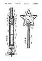
- FIG. 7is a perspective view of an illuminating wand constructed in accordance with the invention.
- FIG. 8is an exploded view of the illuminating wand of the present invention.
- FIG. 9is a partial sectional view taken along line 9--9 of the illuminating wand of FIG. 7;
- FIG. 10is a partial sectional view taken along line 10--10 of the illuminating wand of FIG. 7;
- FIG. 11is a cross-sectional view taken along line 11--11 of the illuminating wand of FIG. 9;
- FIG. 12is a partial sectional view of the wand constructed in accordance with the invention.
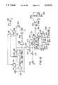
- FIG. 13is a schematic diagram of the circuitry constructed in accordance with a second embodiment of the present invention.
- FIGS. 1-5wherein a light sword, generally indicated as 20 and including a handle assembly (handle) 22 and a light blade assembly 150 is depicted.
- a light swordgenerally indicated as 20 and including a handle assembly (handle) 22 and a light blade assembly 150 is depicted.
- Handle 22 of sword 20has an upper portion 26 and a lower portion 28.
- Handle 22 of sword 20is preferably formed of a thermoplastic that resists breakage.
- Upper portion 26is formed with bores 30, 31, 32 therethrough for receiving a plurality of push switches 34, 35, 36.
- a printed circuit board 40is supported within handle 22.
- a lensed light emitting diode (LED) 44is electrically coupled to printed circuit board 40.
- Printed circuit board 40activates speaker 42 and controls the current flow to LED 44.
- Handle 22is further provided with an internally extending flange 47 defining a well 49.
- a speaker 42 electrically coupled to the circuit of printed circuit board 40is supported within well 49.
- a first end 46 of handle 22is formed with grooves 48 to allow the sound from speaker 42 to radiate out of handle 22.
- a battery housing 50is integrally formed within a lower portion 28 of handle 22.
- Batteries 54fit in battery housing 50 and a battery housing cover 52 snaps on and off of battery housing 50 maintaining batteries 54 in place.
- Battery housing cover 52is preferably formed of the same break-resistant thermoplastic as handle 22.
- Handle 22is further equipped with aesthetically pleasing members 56, which are of the same theme as the type of sword or light saber, which add enhanced play value for the user.
- Push switches, 34, 35, 36activate the circuit of printed circuit board 40 and are displaceable between a first position, wherein they do not contact circuit board 40, and a second position, wherein they are in contact with circuit board 40.
- Printed circuit board 40includes dome switches 80, 82, 84. Push switches 34, 35, 36 contact circuit board 40 at dome switches 80, 82, 84, respectively.
- Light blade assembly 150includes a translucent light rod 70 preferably formed of a thermoplastic such as blow molded polyethylene or the like which is partially resistant to light.
- the blow molded polyethylene light rod 70provides a pathway for the light from LED 44 to travel.
- LED 44is positioned within a first proximate end 71 of light rod.
- the lens of the LED 44focuses the light at a second distal end 72 of light rod 70. Accordingly, hot spots or bright spots may be formed at the first end 71 near LED 44 and at second distal end 72.
- Light rod 70is formed with a rough surface (a surface with many nicks or grooves therein) to prevent light from shining directly through the sides of light rod 70.
- the nicks and grooves or rough spots on the surfaceare capable of receiving the light waves and reflecting and scattering the light waves away from the light rod.
- each nick or groove that reflects a light wave away from the light rodappears to the human eye to be illuminated in the area of that nick or groove.
- the human eyedoes not see that actual light wave, but only sees the reflection and scattering of the light off an object, in this case the nicks or grooves in the light rod.
- light rod 70has substantially uniform illumination across the length of the light rod.
- light rod 70is formed of a material providing some resistance to light, i.e. the light travel distance (the portion of the light rod that appears to be illuminated to the viewer) is directly related to beam intensity.
- light beams from LED 44 of low intensitywill not appear to travel the entire length of light rod 70.
- the lightwill appear to travel a greater distance along light rod 70 so that the distal end of the beam will appear to be advancing towards second end 72 of light rod 70 providing the illusion of a moving or "scrolling" light.
- Light assembly 150includes a sword blade 76 formed with a collar 77 adapted to be received in an opening 78 formed in handle 22.
- Light rod 70is disposed within sword blade 76.
- Sword blade 76is made of a thermoplastic material that is not opaque, so that the light radiating from light sword 70 can cause sword blade 76 to become substantially uniformally illuminated.
- Push switch 35is then pushed and speaker 42 is caused to output the sound of a light sword in motion.
- Push switch 36is then pushed turning OFF LED 44, extinguishing the light in light rod 70 and causing speaker 42 to output a sound associated with the turning OFF of a light sword.
- An astable clock 90includes a first inverter 160 which provides an output to a capacitor 162.
- Capacitor 162is coupled to a second inverter 164 through a resistor 166.
- Capacitor 162also provides an input to inverter 160 through resistor 94.
- a feedback inputis also provided to inverter 160 by inverter 164.
- Inverter 160outputs signal 92 which oscillates at approximately 18 Hz.
- Signal 92provides an oscillating input to the base of gating transistor 98 through a resistor 96.
- the collector of transistor 98is coupled to batteries 54 through current limiting resistor 172.
- the drain 99 of a metal oxide semiconductor field effect transistor (MOSFET) 100is coupled to the emitter of transistor 98.
- LED 44is coupled between the source 101 of MOSFET 100 and ground.
- MOSFETmetal oxide semiconductor field effect transistor
- Battery 54is coupled to the gate 103 of MOSFET 100 through a double throw dipole switch 80 and a resistor 106.
- a capacitor 108is coupled between ground and gate 103.
- Switch 84is also a double throw dipole switch which is coupled between ground and resistor 106.
- the gate 103 of MOSFET 100receives power from battery 54 through switch 80 and resistor 106.
- Capacitor 108also coupled to gate 103, stores electrical energy supplied by batteries 54 when switch 80 is closed.
- capacitor 108has a capacitance of 1 ⁇ F and resistor 106 has a resistance of 100 K ⁇ . However, these values may vary in accordance with the effect desired.
- Basic astable clock 90outputs a clock signal 92.
- the clock signal 92is a square wave of approximately 18 Hz.
- Resistor 94is varied until output signal 92 is 18 Hz.
- the 18 Hz signalis preferred because it is below the persistence of vision producing a strobe effect that the eye can barely detect. Accordingly, when the circuit is on, LED 44 will strobe and an animated light effect will be seen by the user.
- BJTbipolar junction transistor
- Switch 80turns MOSFET 100 ON.
- switch 102When switch 102 is depressed, a positive signal from battery 54 is input through resistor 106 charging capacitor 108. Since the scrolling effect is dependent on the current applied to LED 44, when resistor 106 is increased in resistance the scrolling effect is slower, and when it is lower in value the scrolling effect is quicker.
- the amount of current that may flow between drain 99 and source 101 of MOSFET 100is directly proportional to the voltage at gate 103.
- the voltage at gate 10is the voltage stored in capacitor 108. Accordingly, when capacitor 108 is at ground potential, no current flows from drain 99 to source 101 of MOSFET 100. However, after depression of push switch 102, capacitor 108 stores energy.
- capacitor 108When push switch 102 is only depressed for a short amount of time, capacitor 108 does not fully charge and only a small amount of current can flow between drain 99 and source 101 of MOSFET 100. Accordingly, LED 44 illuminates with little intensity. Therefore, LED 44 cannot effectively illuminate the entire length of light rod 70 from first end 71 to second end 72 and light rod 70 appears less than fully illuminated. However, as push switch 102 is closed for a longer period of time, capacitor 108 fully charges and current freely flows between drain 99 and source 101 of MOSFET 100. Therefore, LED 110 illuminates with a high intensity and light rod 70 becomes fully illuminated providing the appearance of the light scrolling along light blade assembly 150 from a proximate end to a distal end.
- MOSFET 100acts as a voltage controlled resistor and causes the desired scrolling effect of light rod 70. Further, after capacitor 108 is fully charged, push switch 102 no longer needs to be depressed, and diode 110 stays illuminated, strobing with an 18 Hz frequency as determined by clock pulse 92 from basic astable clock 90. MOSFET 100 does not drain capacitor 108. Accordingly, battery power is conserved.
- Switch 84turns LED 44 OFF.
- Capacitor 108is discharged through resistor 106 to ground when switch 84 is depressed closing the circuit.
- Gate 103is at ground potential and no current flows between drain 99 and source 101 of MOSFET 100. Accordingly, LED 44 is non-illuminated.
- a sound chip 120stores sound data at various addresses therein which may be pre-input through audio inputs at the time of manufacture.
- Sound chip 120may be chip number UM 5000 manufactured by the UMC Corporation of Taiwan.
- Sound chip 120receives a first input at terminal 123 and a second input at terminal 127 from batteries 54 through switch 80. Batteries 54 are also coupled directly to sound chip 120 through switches 84 and 82.
- Sound chip 120is also grounded at four leads.
- Capacitor 176is grounded on one side and the other side is coupled to terminal 126 of sound chip 120 and through resistor 178 to terminal 125.
- capacitor 176has a value of approximately 6800 pF and resistor 178 has a value of 680 K ⁇ . These values may vary in accordance with the sound sample speed desired.
- a transistor 135is coupled to chip 120 through an RC circuit formed by a resistor 132 and capacitor 133.
- the collector of transistor 135is coupled to speaker 42 which in turn is coupled in series with a current limiting resistor 131.
- Battery 54is grounded.
- resistor 124has a value of 100 K ⁇
- capacitor 133has a capacitance of 0.15 pF
- resistor 132has a value of between 0 and 18 ⁇ depending upon the desired volume.
- the sound circuitryoperates simultaneously with the operation of LED 44 when switch 80 is depressed.
- a high signalis sent through inverter 122 and current limiting resistor 124. Accordingly, a high signal is input to terminal 123 of sound chip 120. Simultaneously, a high is input to sound chip 120 at terminal 127. This input combination accesses the address for the appropriate sound on sound chip 120 and lead 130 of sound chip 120 outputs the desired sound signal.
- This sound signalis input at the base of BJT 13 through resistor 132.
- Battery 54drives speaker 42 through current limiting resistor 131.
- the sound signal input at the base of the BJT 135gates BJT 135 causing current to flow through speaker 42 and through the collector and emitter of BJT 135 to ground. The sound is emitted from speaker 42 for as long as switch 80 is depressed and turns off when switch 80 is released.
- switch 82is depressed. This provides a single high input to sound chip 120 at input terminal 175. The sound is emitted for as long as switch 82 is depressed and is terminated when switch 82 is released.
- switch 84When switch 84 is activated, a positive signal is input to sound chip 120 at input terminal 177. Accordingly, the address of the appropriate sound signal is accessed and output to lead 130 to activate speaker 42 as noted hereinabove.
- the sound output by speaker 42 when push switch 84 is depressedis a sound that is associated with the light sword becoming inactivated. The sound is produced simultaneously with LED 44 being turned OFF providing the illusion of a real light saber.
- chip size and expensecan be conserved by using the same terminal of sound chip 120 and the same sound for activation and deactivartion of the light sword.
- a light swordwhich illuminates the blade while simultaneously providing sounds associated with an illuminated blade
- a light sword of increased realismproviding an enhanced play value provided by a more realistic light sword
- a mechanism to cause the light of the blade to scroll along the light sworda toy light sword which captures the imagination of the user and provides even greater realism thus enhancing the play value even further is provided.
- FIGS. 7-12wherein an illuminating wand, generally indicated as 200, constructed in accordance with a second embodiment of the invention is provided.
- An illuminating wand 200has a handle assembly (handle) 202 and a light wand assembly 290 coupled to handle 202
- Handle 202has a top portion 212 and a bottom portion 214.
- Top portion 212is formed with a bore 216 therein adapted to receive switch 218 therethrough.
- Handle 202 of wand 200is formed of a thermoplastic material, such as polyvinyl chloride (PVC) and top portion 212 couples with bottom portion 214 by a snap-fit closure. However, top portion 212 and bottom portion 214 may close by any other preferable manner.
- Bottom portion 214 of handle 202is equipped with a first speaker housing section 225.
- Top portion 212 of handle 202is equipped with a speaker housing section 226 which is formed in a decorative shape.
- a speaker 224is disposed within speaker housing sections 225, 226. For exemplary purposes, a heart shape is illustrated. Grooves 228 are cut within speaker housing 226 to allow sound waves to emanate therefrom.
- a battery housing 230 for housing batteries 232is formed in bottom portion 214 of handle 202.
- Battery housing cover 234is provided to maintain batteries 232 within housing 230.
- Battery housing cover 234is preferably formed of a thermoplastic material such as PVC, but may be formed of other materials.
- a printed circuit board 220is supported within handle 202.
- Printed circuit board 220is electrically coupled to speaker 224.
- LED 222is also coupled to the circuit of printed circuit board 220 and is driven thereby.
- LED 222is a lensed LED.
- Batteries 232are electrically coupled to printed circuit board 220 by connection terminals 236, 237.
- Switch 218is movable between a first position in which switch 218 contacts domed switch 221 of printed circuit board 220 and a second position in which switch 218 is not in contact with printed circuit board 220.
- LED 222is turned ON.
- LED 44is turned OFF.
- switch 218causes speaker 224 to produce sounds associated with a magic wand when LED 222 is illuminated.
- Light wand assembly 290includes a translucent light rod 204 having roughed sides.
- Light rod 204provides a pathway for the light of LED 222.
- Light rod 204need not exhibit a scrolling characteristic.
- a decorative wand member 206is adapted to contain light rod 204 therein.
- Light rod 204is enveloped by decorative wand member 206.
- Decorative wand member 206has a first end 207 coupled to handle 202 and a second end 208.
- An aesthetically pleasing head 210is formed at second end 208 of decorative wand member 206.
- Head 210is star-shaped, by way of example, and illuminates when light rod 204 is fully illuminated.
- LED 222illuminates light rod 204.
- the lens of LED 222is focused at second end 205 of light rod 204.
- Light rod 204is formed of a translucent thermoplastic material that may have either a white or pink color to add aesthetic quality for the user.
- light rod 204is blow molded thermoplastic. Again, since light needs a final resting place to illuminate a surface, the surface of light rod 204 is roughed or has many grooves in it becoming translucent to provide a resting place for the light to shine upon, so that light rod 204 illuminates evenly along its surface.
- Handle 202is formed with two (2) upstanding walls 240, 242 defining a groove 244. Groove 244 receives flange 209 of first end 207 of decorative wand 206.
- FIG. 13wherein the circuitry for wand 200 is disclosed.
- the circuit of printed circuit board 220drives light emitting diode 222 and speaker 224.
- An astable clock 310includes a first inverter 400 which provides an output to a capacitor 402.
- Capacitor 402is coupled to a second inverter 404 through a resistor 406.
- Capacitor 402also provides an input to inverter 400 through resistor 314.
- a feedback inputis also provided to inverter 400 by inverter 404.
- the resistance of resistor 314is substantially ten times that of resistor 406.
- Resistor 314has a resistance of 250 K ⁇ , while resistor 406 has resistance of 25 K ⁇ .
- Capacitor 64has a capacitance of 0.22 ⁇ F.
- Inverter 315receives the output of inverter 400 which is a signal which oscillates at approximately 18 Hz. Inverter 315 provides an oscillating input to the base 319 of gating transistor 320 through resistor 318. The collector of transistor 320 is coupled to battery 232 through a current limiting resistor 322. Battery 232 is positioned between resistor 322 and ground.
- LED 222is coupled between the emitter of transistor 320 and the collector of a second transistor 308.
- the emitter of transistor 308is coupled to ground.
- Battery 232is also coupled through a current limiting resistor 410 to switch 221.
- Switch 221is coupled at one end to a capacitor 420 which is coupled to a resistor 422, which is coupled to ground.
- capacitor 420has a capacitance of 0.22 ⁇ F and resistor 422 has a resistance of about 250 K ⁇ .
- Capacitor 420provides an input to an inverter 302 which is coupled to astable clock 60 through diodes 312.
- Inverter 302also provides an input to inverter 304 which is coupled to the base of transistor 308 through resistor 306.
- Basic astable clock 310receives the output of inverter 302 which is fed through diode 312.
- Diode 312is provided to gate oscillator 310 off when switch 300 is open circuited.
- Oscillator 310outputs a square wave signal.
- Resistor 314may be varied to provide the appropriate frequency of oscillation.
- Output signal 311is fed through inverter 315 to provide square wave signal 316.
- Signal 316is fed through current limiting resistor 318 and is fed into base 319 of BJT 320. When base 319 of BJT 320 is high, BJT 320 is turned ON and current may flow between emitter and collector.
- BJT 308 and BJT 320When BJT 308 and BJT 320 are both on, current may flow between batteries 232 through current limiting resistor 322 across emitter and collector of BJT 320 through LED 222, thereby illuminating LED 222, and through collector and emitter of BJT 308 to ground. However, if either transistor 320 or transistor 308 is turned OFF, no current can flow through this section of the circuit and LED 222 will not illuminate.
- Signal 316is provided as a square wave input oscillating at approximately 18 Hz which, as discussed hereinabove with respect to the sword, produces a strobic effect making the wand appear animated to the eye.
- Inverter 330is driven either by battery 234 through resistor 410, or by capacitor 420. Inverter 330 receives a high signal and outputs a low signal to terminal 332 of sound chip 350. Sound chip 350 stores sound data at various addresses therein which may be pre-input through audio inputs during the time of manufacture. Sound chip 350 may be chip No. UM 5000 manufactured by the UMC Corporation of Taiwan, or the like. Sound chip 350 also receives two high signals input from leads 334 and 336 coupled to capacitor 420. A resistor 422 is disposed between leads 334, 336 and ground. Chip 350 is also grounded at two other leads.
- a transistor 355is coupled to chip 350 through an RC circuit formed by a resistor 351 and capacitor 430.
- the collector of transistor 355is coupled to speaker 280 which in turn is coupled in series with a current limiting resistor 357, battery 232 and ground.
- the emitter of transistor 355is coupled to ground so that when transistor 355 is enabled, a current passes from battery 78 through speaker 224 to ground is provided.
- a sound signal generated by sound chip 350 corresponding to the sound stored at the address indicated by the inputs of inverter 330 and terminals 334, 336is input to transistor 355 through the RC circuit formed by resistor 351 and capacitor 430 causing sound to be generated by speaker 280 in response to the sound signal.
- resistor 340has a value of 100 K ⁇
- capacitor 430has a capacitance of 0.15 pF
- resistor 351has a value of between 0 and 18 ⁇ , depending upon the desired volume.
- Sound chip 350receives input from battery 232 at terminal 450.
- Capacitor 452is grounded on one side and the other side is coupled to sound chip 120 in parallel to terminal 454 and through resistor 458 to terminal 456.
- capacitor 452has a value of 6800 pF and resistor 458 has a value of 680 K ⁇ . However, these values may vary in accordance with the sound sample rate desired.
- Battery 232is connected to piezo sensor 460 which is connected to capacitor 462.
- the other side of capacitor 462is connected to resistor 464 which is connected to terminal 470.
- Piezo sensor 460activates upon impact to provide a second magical sound when wand 200 strikes an object.
- capacitor 462is 1 ⁇ F and resistor 464 is adjustable to vary the sensitivity of piezo sensor 460.
- this inventionincorporates the use of a lensed diode focused at the far end of a light rod, the light rod being formed with a rough surface such that the light emanating from the LED may equally light the entire light rod.
- the LEDstrobes at a rate of approximately 18 Hz, so that an animated strobing effect is given to the light rod or decorative casing covering the light rod.
- sounds associated with a magic wandare incorporated with the light rod and are emitted simultaneously with the lighting of the wand to add enhanced play value for the user.
- the combination of light and soundproduces a combination which creates an illusion of realism that provides enhanced play value for the user.
Landscapes
- Toys (AREA)
- Light Guides In General And Applications Therefor (AREA)
Abstract
Description
Claims (22)
Priority Applications (5)
| Application Number | Priority Date | Filing Date | Title |
|---|---|---|---|
| US07/800,915US5279513A (en) | 1991-11-27 | 1991-11-27 | Illuminating toy |
| EP93900618AEP0614394A4 (en) | 1991-11-27 | 1992-11-25 | An illuminating toy. |
| CA002122918ACA2122918A1 (en) | 1991-11-27 | 1992-11-25 | An illuminating toy |
| JP51022893AJP3226275B2 (en) | 1991-11-27 | 1992-11-25 | Luminous toy |
| PCT/US1992/010154WO1993010872A1 (en) | 1991-11-27 | 1992-11-25 | An illuminating toy |
Applications Claiming Priority (1)
| Application Number | Priority Date | Filing Date | Title |
|---|---|---|---|
| US07/800,915US5279513A (en) | 1991-11-27 | 1991-11-27 | Illuminating toy |
Publications (1)
| Publication Number | Publication Date |
|---|---|
| US5279513Atrue US5279513A (en) | 1994-01-18 |
Family
ID=25179697
Family Applications (1)
| Application Number | Title | Priority Date | Filing Date |
|---|---|---|---|
| US07/800,915Expired - Fee RelatedUS5279513A (en) | 1991-11-27 | 1991-11-27 | Illuminating toy |
Country Status (5)
| Country | Link |
|---|---|
| US (1) | US5279513A (en) |
| EP (1) | EP0614394A4 (en) |
| JP (1) | JP3226275B2 (en) |
| CA (1) | CA2122918A1 (en) |
| WO (1) | WO1993010872A1 (en) |
Cited By (60)
| Publication number | Priority date | Publication date | Assignee | Title |
|---|---|---|---|---|
| US5820438A (en)* | 1996-12-24 | 1998-10-13 | Horton, Iii; Larkin | Toy bat |
| US5947789A (en)* | 1997-07-28 | 1999-09-07 | Thinkway Trading Corporation | Toy sword having a variable color illuminated blade |
| US6012820A (en)* | 1998-01-13 | 2000-01-11 | 3M Innovative Properties Compnay | Lighted hand-holdable novelty article |
| US6036576A (en)* | 1998-08-10 | 2000-03-14 | Colon, Jr.; Gilbert | Light sword toy with moving internal object |
| US6082876A (en)* | 1998-01-13 | 2000-07-04 | 3M Innovative Properties Company | Hand-holdable toy light tube with color changing film |
| US6095661A (en)* | 1998-03-19 | 2000-08-01 | Ppt Vision, Inc. | Method and apparatus for an L.E.D. flashlight |
| US6145612A (en)* | 1997-10-06 | 2000-11-14 | Sunrise Medical Hhg Inc. | Removable battery case with locking mechanism for a powered wheelchair |
| US6244723B1 (en)* | 2000-01-10 | 2001-06-12 | John Talamo | Lighted wand for use at night having novel light pattern |
| US20020048169A1 (en)* | 1997-08-26 | 2002-04-25 | Dowling Kevin J. | Light-emitting diode based products |
| US20030019145A1 (en)* | 2000-09-18 | 2003-01-30 | W.C. Bradley/Zebco Holdings, Inc. | Battery powered lighted rod |
| US6626728B2 (en)* | 2000-06-27 | 2003-09-30 | Kenneth C. Holt | Motion-sequence activated toy wand |
| US20040032337A1 (en)* | 2001-11-26 | 2004-02-19 | Kan-Yi Chen | Flashlight adapted for use with a plastic beverage bottle to form a signaling torch |
| US20040136180A1 (en)* | 2003-01-13 | 2004-07-15 | Lewis Edward D. | Ultraviolet illuminated fluorescent writing instrument |
| US20040141321A1 (en)* | 2002-11-20 | 2004-07-22 | Color Kinetics, Incorporated | Lighting and other perceivable effects for toys and other consumer products |
| US6788411B1 (en) | 1999-07-08 | 2004-09-07 | Ppt Vision, Inc. | Method and apparatus for adjusting illumination angle |
| US20050029168A1 (en)* | 2003-08-01 | 2005-02-10 | Jones William J. | Currency processing device, method and system |
| US20050159072A1 (en)* | 2003-10-17 | 2005-07-21 | Brown Matthew P.D. | Dress-up activity toy |
| US6945842B1 (en) | 2004-05-04 | 2005-09-20 | Andre Arturo Gulmesoff | Toy sword with contact indicator |
| US20060040720A1 (en)* | 2004-08-23 | 2006-02-23 | Harrison Shelton E Jr | Integrated game system, method, and device |
| US20060056167A1 (en)* | 2004-09-15 | 2006-03-16 | Weigl James A Jr | Illuminating utensil |
| US7064498B2 (en) | 1997-08-26 | 2006-06-20 | Color Kinetics Incorporated | Light-emitting diode based products |
| US20070008718A1 (en)* | 2005-07-05 | 2007-01-11 | Cayton Paul E | Pumpkin illumination stake |
| US7186003B2 (en) | 1997-08-26 | 2007-03-06 | Color Kinetics Incorporated | Light-emitting diode based products |
| US20070139951A1 (en)* | 2005-12-15 | 2007-06-21 | Adam Dick | Light-emitting device |
| US20090093183A1 (en)* | 2007-09-01 | 2009-04-09 | Bernadine Marie Randle | Novelty light-up and action toy |
| US20090124165A1 (en)* | 2000-10-20 | 2009-05-14 | Creative Kingdoms, Llc | Wireless toy systems and methods for interactive entertainment |
| USD603464S1 (en)* | 2009-06-26 | 2009-11-03 | Christopher Kelly | Illuminated toy light saber |
| US7625289B1 (en)* | 2006-05-31 | 2009-12-01 | John Fagliarone | Martial arts demonstration staff |
| WO2010019219A1 (en)* | 2008-08-13 | 2010-02-18 | Kevin Joseph Hathaway | Light-pipe based identification and location signaling light |
| US7740371B1 (en) | 1998-03-19 | 2010-06-22 | Charles A. Lemaire | Method and apparatus for pulsed L.E.D. illumination for a camera |
| USD622327S1 (en)* | 2010-01-12 | 2010-08-24 | Christian Roos | Illuminating handle for a toy |
| USD624133S1 (en)* | 2009-12-07 | 2010-09-21 | Kelly Christopher D | Light up twist handle |
| US20110204825A1 (en)* | 2010-02-22 | 2011-08-25 | Wei Hung Yu | Light stick with a dazzling effect |
| US8089458B2 (en) | 2000-02-22 | 2012-01-03 | Creative Kingdoms, Llc | Toy devices and methods for providing an interactive play experience |
| US8226493B2 (en) | 2002-08-01 | 2012-07-24 | Creative Kingdoms, Llc | Interactive play devices for water play attractions |
| US8475275B2 (en) | 2000-02-22 | 2013-07-02 | Creative Kingdoms, Llc | Interactive toys and games connecting physical and virtual play environments |
| US8608535B2 (en) | 2002-04-05 | 2013-12-17 | Mq Gaming, Llc | Systems and methods for providing an interactive game |
| US8702515B2 (en) | 2002-04-05 | 2014-04-22 | Mq Gaming, Llc | Multi-platform gaming system using RFID-tagged toys |
| US8708821B2 (en) | 2000-02-22 | 2014-04-29 | Creative Kingdoms, Llc | Systems and methods for providing interactive game play |
| US8758136B2 (en) | 1999-02-26 | 2014-06-24 | Mq Gaming, Llc | Multi-platform gaming systems and methods |
| CN103949064A (en)* | 2014-04-15 | 2014-07-30 | 樊书印 | Electronic striking stick |
| WO2015031870A1 (en)* | 2013-09-02 | 2015-03-05 | Kma Concepts Limited | Toy bow and arrow system with internal bow lighting |
| WO2015157918A1 (en)* | 2014-04-15 | 2015-10-22 | 樊书印 | Electronic percussion stick |
| US9310171B2 (en) | 2010-09-09 | 2016-04-12 | Kma Concepts Limited | Toy arrow for use with toy bow |
| US9341448B2 (en) | 2014-04-04 | 2016-05-17 | Kma Concepts Limited | Shafted projectiles having a head |
| US9446319B2 (en) | 2003-03-25 | 2016-09-20 | Mq Gaming, Llc | Interactive gaming toy |
| US9522321B2 (en) | 2010-09-09 | 2016-12-20 | Kma Concepts Limited | Toy bow and arrow system with internal bow lighting |
| US9630120B2 (en)* | 2014-07-12 | 2017-04-25 | Leonard J. Stubenfoll | Toy or game with illuminable tube |
| US10065127B1 (en)* | 2017-03-16 | 2018-09-04 | Disney Enterprises, Inc. | Sword device with retractable, internally illuminated blade |
| CN108888972A (en)* | 2018-09-26 | 2018-11-27 | 台山燊乐塑胶电子制造有限公司 | A kind of toy sword |
| USD847267S1 (en)* | 2016-10-18 | 2019-04-30 | Renee Faith Gold | Wand with chiming sphere |
| US10500518B2 (en)* | 2017-07-24 | 2019-12-10 | Jomoko T. Graves | Toy retractable light saber |
| CN110960870A (en)* | 2018-09-30 | 2020-04-07 | 台山燊乐塑胶电子制造有限公司 | Pair-fighting combined sword |
| CN110960869A (en)* | 2018-09-30 | 2020-04-07 | 台山燊乐塑胶电子制造有限公司 | Toy sword |
| USD909492S1 (en)* | 2018-01-15 | 2021-02-02 | Derrick S. Brown | Star-shaped cheering stick |
| US20220088498A1 (en)* | 2019-06-04 | 2022-03-24 | Hasbro, Inc. | Telescopic item and mechanism therefor |
| US11484810B2 (en)* | 2018-10-03 | 2022-11-01 | Groupe Ldlc | Accessory of light-sabre type |
| US20220410416A1 (en)* | 2022-08-29 | 2022-12-29 | Changsha Mobile Electronic Technology Co., Ltd. | Assembled visual machete |
| US20230102102A1 (en)* | 2021-09-30 | 2023-03-30 | Mbissine M. Ngom | Device and system for a light stick sleeve |
| RU2828946C1 (en)* | 2024-03-04 | 2024-10-21 | Артём Михайлович Костромин | Interactive apparatus for complex systems of sports training |
Families Citing this family (12)
| Publication number | Priority date | Publication date | Assignee | Title |
|---|---|---|---|---|
| JPH07148346A (en)* | 1993-11-26 | 1995-06-13 | Sega Enterp Ltd | Ray gun for games |
| JP2007044482A (en)* | 2005-07-15 | 2007-02-22 | Konami Digital Entertainment:Kk | Grip toy |
| CN103949062B (en)* | 2014-04-15 | 2016-04-27 | 邢皓宇 | A kind of electronics stamp |
| CN103949060B (en)* | 2014-04-15 | 2016-04-27 | 邢皓宇 | A kind of electronics stamp |
| CN103949065B (en)* | 2014-04-15 | 2016-04-27 | 邢皓宇 | A kind of electronics stamp |
| CN103949061B (en)* | 2014-04-15 | 2016-04-27 | 邢皓宇 | A kind of electronics stamp |
| CN103949066B (en)* | 2014-04-15 | 2016-05-18 | 邢皓宇 | A kind of electronics stamp |
| CN103949059B (en)* | 2014-04-15 | 2016-04-27 | 邢皓宇 | A kind of electronics stamp |
| CN103949058B (en)* | 2014-04-15 | 2016-07-06 | 邢皓宇 | A kind of electronics stamp |
| JP6390914B2 (en)* | 2014-06-13 | 2018-09-19 | 株式会社サンセイアールアンドディ | Pachinko machine |
| RU2660511C1 (en)* | 2017-03-23 | 2018-07-06 | Евгений Янович Колчинский | Light-noise device |
| JP6586498B1 (en)* | 2018-09-27 | 2019-10-02 | 株式会社バンダイ | Model toy |
Citations (11)
| Publication number | Priority date | Publication date | Assignee | Title |
|---|---|---|---|---|
| US2734310A (en)* | 1956-02-14 | christopher | ||
| US3397484A (en)* | 1965-10-22 | 1968-08-20 | Mattel Inc | Sound and optical effects toy |
| US3570176A (en)* | 1968-12-13 | 1971-03-16 | Henry J Palmer | Toy machine gun |
| US4171811A (en)* | 1978-02-10 | 1979-10-23 | Marvin Glass & Associates | Light gun with photo detector and counter |
| US4175353A (en)* | 1978-01-03 | 1979-11-27 | Pickett Vaughn A | Toy simulated ray gun |
| US4365439A (en)* | 1980-09-02 | 1982-12-28 | Zbigniew Litynski | Toy laser-type gun |
| US4678450A (en)* | 1982-12-27 | 1987-07-07 | Life Light Systems | Toy light sword |
| US4750641A (en)* | 1986-09-24 | 1988-06-14 | Chin Fu Hun | Continuous water-ejecting pistol toy with simultaneous sound and red-flash effects |
| GB2199256A (en)* | 1986-12-16 | 1988-07-06 | Wong Shun Fan | A Toy sword |
| US4904222A (en)* | 1988-04-27 | 1990-02-27 | Pennwalt Corporation | Synchronized sound producing amusement device |
| US5059150A (en)* | 1990-11-26 | 1991-10-22 | Kuo Tien H | Vibrating and sonic device for toy gun |
- 1991
- 1991-11-27USUS07/800,915patent/US5279513A/ennot_activeExpired - Fee Related
- 1992
- 1992-11-25CACA002122918Apatent/CA2122918A1/ennot_activeAbandoned
- 1992-11-25WOPCT/US1992/010154patent/WO1993010872A1/ennot_activeApplication Discontinuation
- 1992-11-25JPJP51022893Apatent/JP3226275B2/ennot_activeExpired - Fee Related
- 1992-11-25EPEP93900618Apatent/EP0614394A4/ennot_activeCeased
Patent Citations (11)
| Publication number | Priority date | Publication date | Assignee | Title |
|---|---|---|---|---|
| US2734310A (en)* | 1956-02-14 | christopher | ||
| US3397484A (en)* | 1965-10-22 | 1968-08-20 | Mattel Inc | Sound and optical effects toy |
| US3570176A (en)* | 1968-12-13 | 1971-03-16 | Henry J Palmer | Toy machine gun |
| US4175353A (en)* | 1978-01-03 | 1979-11-27 | Pickett Vaughn A | Toy simulated ray gun |
| US4171811A (en)* | 1978-02-10 | 1979-10-23 | Marvin Glass & Associates | Light gun with photo detector and counter |
| US4365439A (en)* | 1980-09-02 | 1982-12-28 | Zbigniew Litynski | Toy laser-type gun |
| US4678450A (en)* | 1982-12-27 | 1987-07-07 | Life Light Systems | Toy light sword |
| US4750641A (en)* | 1986-09-24 | 1988-06-14 | Chin Fu Hun | Continuous water-ejecting pistol toy with simultaneous sound and red-flash effects |
| GB2199256A (en)* | 1986-12-16 | 1988-07-06 | Wong Shun Fan | A Toy sword |
| US4904222A (en)* | 1988-04-27 | 1990-02-27 | Pennwalt Corporation | Synchronized sound producing amusement device |
| US5059150A (en)* | 1990-11-26 | 1991-10-22 | Kuo Tien H | Vibrating and sonic device for toy gun |
Non-Patent Citations (2)
| Title |
|---|
| "Fairyland" Magic Light Up Wand, Brochure from Bantamlite, Inc., 1966,. |
| Fairyland Magic Light Up Wand, Brochure from Bantamlite, Inc., 1966,.* |
Cited By (167)
| Publication number | Priority date | Publication date | Assignee | Title |
|---|---|---|---|---|
| US5820438A (en)* | 1996-12-24 | 1998-10-13 | Horton, Iii; Larkin | Toy bat |
| US5947789A (en)* | 1997-07-28 | 1999-09-07 | Thinkway Trading Corporation | Toy sword having a variable color illuminated blade |
| US20020048169A1 (en)* | 1997-08-26 | 2002-04-25 | Dowling Kevin J. | Light-emitting diode based products |
| US7186003B2 (en) | 1997-08-26 | 2007-03-06 | Color Kinetics Incorporated | Light-emitting diode based products |
| US20050236998A1 (en)* | 1997-08-26 | 2005-10-27 | Color Kinetics, Inc. | Light emitting diode based products |
| US7064498B2 (en) | 1997-08-26 | 2006-06-20 | Color Kinetics Incorporated | Light-emitting diode based products |
| US20070195526A1 (en)* | 1997-08-26 | 2007-08-23 | Color Kinetics Incorporated | Wireless lighting control methods and apparatus |
| US7659674B2 (en) | 1997-08-26 | 2010-02-09 | Philips Solid-State Lighting Solutions, Inc. | Wireless lighting control methods and apparatus |
| US20030206411A9 (en)* | 1997-08-26 | 2003-11-06 | Dowling Kevin J. | Light-emitting diode based products |
| US6145612A (en)* | 1997-10-06 | 2000-11-14 | Sunrise Medical Hhg Inc. | Removable battery case with locking mechanism for a powered wheelchair |
| US6082876A (en)* | 1998-01-13 | 2000-07-04 | 3M Innovative Properties Company | Hand-holdable toy light tube with color changing film |
| US6641280B2 (en) | 1998-01-13 | 2003-11-04 | 3M Innovative Properties Company | Hand-holdable toy light tube |
| US6012820A (en)* | 1998-01-13 | 2000-01-11 | 3M Innovative Properties Compnay | Lighted hand-holdable novelty article |
| US8159146B1 (en) | 1998-03-19 | 2012-04-17 | Lemaire Illumination Technologies, Llc | Apparatus and method for pulsed L.E.D. illumination |
| US6808287B2 (en) | 1998-03-19 | 2004-10-26 | Ppt Vision, Inc. | Method and apparatus for a pulsed L.E.D. illumination source |
| US20030095406A1 (en)* | 1998-03-19 | 2003-05-22 | Ppt Vision, Inc. | Method and apparatus for a pulsed L.E.D. illumination source |
| US7740371B1 (en) | 1998-03-19 | 2010-06-22 | Charles A. Lemaire | Method and apparatus for pulsed L.E.D. illumination for a camera |
| US8362712B1 (en) | 1998-03-19 | 2013-01-29 | Led Tech Development, Llc | Apparatus and method for L.E.D. illumination |
| US6488390B1 (en) | 1998-03-19 | 2002-12-03 | Ppt Vision, Inc. | Color-adjusted camera light and method |
| US8829808B1 (en) | 1998-03-19 | 2014-09-09 | Led Tech Development, Llc | Apparatus and method for pulsed L.E.D. illumination |
| US8643305B2 (en) | 1998-03-19 | 2014-02-04 | Lemaire Illumination Technologies, Llc | Apparatus for L.E.D. illumination |
| US7393119B2 (en) | 1998-03-19 | 2008-07-01 | Charles A. Lemaire | Method and apparatus for constant light output pulsed L.E.D. illumination |
| US20050040773A1 (en)* | 1998-03-19 | 2005-02-24 | Ppt Vision, Inc. | Method and apparatus for a variable intensity pulsed L.E.D. light |
| US9907137B1 (en) | 1998-03-19 | 2018-02-27 | Lemaire Illumination Technologies, Llc | Pulsed L.E.D. illumination |
| US6305818B1 (en) | 1998-03-19 | 2001-10-23 | Ppt Vision, Inc. | Method and apparatus for L.E.D. illumination |
| US20070133199A1 (en)* | 1998-03-19 | 2007-06-14 | Charles Lemaire | Method and apparatus for a pulsed l.e.d. illumination |
| US7186000B2 (en) | 1998-03-19 | 2007-03-06 | Lebens Gary A | Method and apparatus for a variable intensity pulsed L.E.D. light |
| US6095661A (en)* | 1998-03-19 | 2000-08-01 | Ppt Vision, Inc. | Method and apparatus for an L.E.D. flashlight |
| US6036576A (en)* | 1998-08-10 | 2000-03-14 | Colon, Jr.; Gilbert | Light sword toy with moving internal object |
| US8758136B2 (en) | 1999-02-26 | 2014-06-24 | Mq Gaming, Llc | Multi-platform gaming systems and methods |
| US9861887B1 (en)* | 1999-02-26 | 2018-01-09 | Mq Gaming, Llc | Multi-platform gaming systems and methods |
| US9468854B2 (en) | 1999-02-26 | 2016-10-18 | Mq Gaming, Llc | Multi-platform gaming systems and methods |
| US10300374B2 (en)* | 1999-02-26 | 2019-05-28 | Mq Gaming, Llc | Multi-platform gaming systems and methods |
| US9186585B2 (en) | 1999-02-26 | 2015-11-17 | Mq Gaming, Llc | Multi-platform gaming systems and methods |
| US9731194B2 (en)* | 1999-02-26 | 2017-08-15 | Mq Gaming, Llc | Multi-platform gaming systems and methods |
| US8888576B2 (en) | 1999-02-26 | 2014-11-18 | Mq Gaming, Llc | Multi-media interactive play system |
| US7142301B2 (en) | 1999-07-08 | 2006-11-28 | Ppt Vision | Method and apparatus for adjusting illumination angle |
| US6788411B1 (en) | 1999-07-08 | 2004-09-07 | Ppt Vision, Inc. | Method and apparatus for adjusting illumination angle |
| US6244723B1 (en)* | 2000-01-10 | 2001-06-12 | John Talamo | Lighted wand for use at night having novel light pattern |
| US8814688B2 (en) | 2000-02-22 | 2014-08-26 | Creative Kingdoms, Llc | Customizable toy for playing a wireless interactive game having both physical and virtual elements |
| US8686579B2 (en) | 2000-02-22 | 2014-04-01 | Creative Kingdoms, Llc | Dual-range wireless controller |
| US9149717B2 (en) | 2000-02-22 | 2015-10-06 | Mq Gaming, Llc | Dual-range wireless interactive entertainment device |
| US8915785B2 (en) | 2000-02-22 | 2014-12-23 | Creative Kingdoms, Llc | Interactive entertainment system |
| US10188953B2 (en) | 2000-02-22 | 2019-01-29 | Mq Gaming, Llc | Dual-range wireless interactive entertainment device |
| US9814973B2 (en) | 2000-02-22 | 2017-11-14 | Mq Gaming, Llc | Interactive entertainment system |
| US9713766B2 (en) | 2000-02-22 | 2017-07-25 | Mq Gaming, Llc | Dual-range wireless interactive entertainment device |
| US9474962B2 (en)* | 2000-02-22 | 2016-10-25 | Mq Gaming, Llc | Interactive entertainment system |
| US8790180B2 (en) | 2000-02-22 | 2014-07-29 | Creative Kingdoms, Llc | Interactive game and associated wireless toy |
| US8184097B1 (en) | 2000-02-22 | 2012-05-22 | Creative Kingdoms, Llc | Interactive gaming system and method using motion-sensitive input device |
| US9579568B2 (en) | 2000-02-22 | 2017-02-28 | Mq Gaming, Llc | Dual-range wireless interactive entertainment device |
| US10307671B2 (en) | 2000-02-22 | 2019-06-04 | Mq Gaming, Llc | Interactive entertainment system |
| US8708821B2 (en) | 2000-02-22 | 2014-04-29 | Creative Kingdoms, Llc | Systems and methods for providing interactive game play |
| US20150094140A1 (en)* | 2000-02-22 | 2015-04-02 | Creative Kingdoms, Llc | Interactive entertainment system |
| US20190366204A1 (en)* | 2000-02-22 | 2019-12-05 | Mq Gaming, Llc | Interactive entertainment system |
| US8169406B2 (en) | 2000-02-22 | 2012-05-01 | Creative Kingdoms, Llc | Motion-sensitive wand controller for a game |
| US8531050B2 (en) | 2000-02-22 | 2013-09-10 | Creative Kingdoms, Llc | Wirelessly powered gaming device |
| US8491389B2 (en) | 2000-02-22 | 2013-07-23 | Creative Kingdoms, Llc. | Motion-sensitive input device and interactive gaming system |
| US8475275B2 (en) | 2000-02-22 | 2013-07-02 | Creative Kingdoms, Llc | Interactive toys and games connecting physical and virtual play environments |
| US8368648B2 (en) | 2000-02-22 | 2013-02-05 | Creative Kingdoms, Llc | Portable interactive toy with radio frequency tracking device |
| US8164567B1 (en) | 2000-02-22 | 2012-04-24 | Creative Kingdoms, Llc | Motion-sensitive game controller with optional display screen |
| US8089458B2 (en) | 2000-02-22 | 2012-01-03 | Creative Kingdoms, Llc | Toy devices and methods for providing an interactive play experience |
| US6626728B2 (en)* | 2000-06-27 | 2003-09-30 | Kenneth C. Holt | Motion-sequence activated toy wand |
| US7051470B2 (en)* | 2000-09-18 | 2006-05-30 | W.C. Bradley/Zebco Holdings, Inc. | Battery powered lighted rod |
| US20030019145A1 (en)* | 2000-09-18 | 2003-01-30 | W.C. Bradley/Zebco Holdings, Inc. | Battery powered lighted rod |
| US8753165B2 (en) | 2000-10-20 | 2014-06-17 | Mq Gaming, Llc | Wireless toy systems and methods for interactive entertainment |
| US9320976B2 (en) | 2000-10-20 | 2016-04-26 | Mq Gaming, Llc | Wireless toy systems and methods for interactive entertainment |
| US8961260B2 (en) | 2000-10-20 | 2015-02-24 | Mq Gaming, Llc | Toy incorporating RFID tracking device |
| US20090124165A1 (en)* | 2000-10-20 | 2009-05-14 | Creative Kingdoms, Llc | Wireless toy systems and methods for interactive entertainment |
| US9931578B2 (en) | 2000-10-20 | 2018-04-03 | Mq Gaming, Llc | Toy incorporating RFID tag |
| US10307683B2 (en) | 2000-10-20 | 2019-06-04 | Mq Gaming, Llc | Toy incorporating RFID tag |
| US9480929B2 (en) | 2000-10-20 | 2016-11-01 | Mq Gaming, Llc | Toy incorporating RFID tag |
| US10758818B2 (en) | 2001-02-22 | 2020-09-01 | Mq Gaming, Llc | Wireless entertainment device, system, and method |
| US8384668B2 (en) | 2001-02-22 | 2013-02-26 | Creative Kingdoms, Llc | Portable gaming device and gaming system combining both physical and virtual play elements |
| US10179283B2 (en) | 2001-02-22 | 2019-01-15 | Mq Gaming, Llc | Wireless entertainment device, system, and method |
| US9162148B2 (en) | 2001-02-22 | 2015-10-20 | Mq Gaming, Llc | Wireless entertainment device, system, and method |
| US8248367B1 (en) | 2001-02-22 | 2012-08-21 | Creative Kingdoms, Llc | Wireless gaming system combining both physical and virtual play elements |
| US8913011B2 (en) | 2001-02-22 | 2014-12-16 | Creative Kingdoms, Llc | Wireless entertainment device, system, and method |
| US9393491B2 (en) | 2001-02-22 | 2016-07-19 | Mq Gaming, Llc | Wireless entertainment device, system, and method |
| US9737797B2 (en) | 2001-02-22 | 2017-08-22 | Mq Gaming, Llc | Wireless entertainment device, system, and method |
| US8711094B2 (en) | 2001-02-22 | 2014-04-29 | Creative Kingdoms, Llc | Portable gaming device and gaming system combining both physical and virtual play elements |
| US20040032337A1 (en)* | 2001-11-26 | 2004-02-19 | Kan-Yi Chen | Flashlight adapted for use with a plastic beverage bottle to form a signaling torch |
| US6909360B2 (en)* | 2001-11-26 | 2005-06-21 | Kan-Yi Chen | Flashlight adapted for use with a plastic beverage bottle to form a signaling torch |
| US10478719B2 (en) | 2002-04-05 | 2019-11-19 | Mq Gaming, Llc | Methods and systems for providing personalized interactive entertainment |
| US8702515B2 (en) | 2002-04-05 | 2014-04-22 | Mq Gaming, Llc | Multi-platform gaming system using RFID-tagged toys |
| US9616334B2 (en) | 2002-04-05 | 2017-04-11 | Mq Gaming, Llc | Multi-platform gaming system using RFID-tagged toys |
| US11278796B2 (en) | 2002-04-05 | 2022-03-22 | Mq Gaming, Llc | Methods and systems for providing personalized interactive entertainment |
| US8827810B2 (en) | 2002-04-05 | 2014-09-09 | Mq Gaming, Llc | Methods for providing interactive entertainment |
| US9272206B2 (en) | 2002-04-05 | 2016-03-01 | Mq Gaming, Llc | System and method for playing an interactive game |
| US10010790B2 (en) | 2002-04-05 | 2018-07-03 | Mq Gaming, Llc | System and method for playing an interactive game |
| US8608535B2 (en) | 2002-04-05 | 2013-12-17 | Mq Gaming, Llc | Systems and methods for providing an interactive game |
| US10507387B2 (en) | 2002-04-05 | 2019-12-17 | Mq Gaming, Llc | System and method for playing an interactive game |
| US9463380B2 (en) | 2002-04-05 | 2016-10-11 | Mq Gaming, Llc | System and method for playing an interactive game |
| US8226493B2 (en) | 2002-08-01 | 2012-07-24 | Creative Kingdoms, Llc | Interactive play devices for water play attractions |
| US20040141321A1 (en)* | 2002-11-20 | 2004-07-22 | Color Kinetics, Incorporated | Lighting and other perceivable effects for toys and other consumer products |
| US20040136180A1 (en)* | 2003-01-13 | 2004-07-15 | Lewis Edward D. | Ultraviolet illuminated fluorescent writing instrument |
| US10369463B2 (en) | 2003-03-25 | 2019-08-06 | Mq Gaming, Llc | Wireless interactive game having both physical and virtual elements |
| US9393500B2 (en) | 2003-03-25 | 2016-07-19 | Mq Gaming, Llc | Wireless interactive game having both physical and virtual elements |
| US10022624B2 (en) | 2003-03-25 | 2018-07-17 | Mq Gaming, Llc | Wireless interactive game having both physical and virtual elements |
| US9707478B2 (en) | 2003-03-25 | 2017-07-18 | Mq Gaming, Llc | Motion-sensitive controller and associated gaming applications |
| US8961312B2 (en) | 2003-03-25 | 2015-02-24 | Creative Kingdoms, Llc | Motion-sensitive controller and associated gaming applications |
| US9993724B2 (en) | 2003-03-25 | 2018-06-12 | Mq Gaming, Llc | Interactive gaming toy |
| US11052309B2 (en) | 2003-03-25 | 2021-07-06 | Mq Gaming, Llc | Wireless interactive game having both physical and virtual elements |
| US9039533B2 (en) | 2003-03-25 | 2015-05-26 | Creative Kingdoms, Llc | Wireless interactive game having both physical and virtual elements |
| US9770652B2 (en) | 2003-03-25 | 2017-09-26 | Mq Gaming, Llc | Wireless interactive game having both physical and virtual elements |
| US8373659B2 (en) | 2003-03-25 | 2013-02-12 | Creative Kingdoms, Llc | Wirelessly-powered toy for gaming |
| US10583357B2 (en) | 2003-03-25 | 2020-03-10 | Mq Gaming, Llc | Interactive gaming toy |
| US9446319B2 (en) | 2003-03-25 | 2016-09-20 | Mq Gaming, Llc | Interactive gaming toy |
| US20050029168A1 (en)* | 2003-08-01 | 2005-02-10 | Jones William J. | Currency processing device, method and system |
| US20050159072A1 (en)* | 2003-10-17 | 2005-07-21 | Brown Matthew P.D. | Dress-up activity toy |
| US6945842B1 (en) | 2004-05-04 | 2005-09-20 | Andre Arturo Gulmesoff | Toy sword with contact indicator |
| US20050250417A1 (en)* | 2004-05-04 | 2005-11-10 | Gulmesoff Andre A | Toy sword with contact indicator |
| US7033242B2 (en) | 2004-05-04 | 2006-04-25 | Andre Arturo Gulmesoff | Toy sword with contact indicator |
| US6951499B1 (en) | 2004-05-04 | 2005-10-04 | Andre Arturo Gulmesoff | Toy sword with contact indicator |
| US20060040720A1 (en)* | 2004-08-23 | 2006-02-23 | Harrison Shelton E Jr | Integrated game system, method, and device |
| US7704135B2 (en) | 2004-08-23 | 2010-04-27 | Harrison Jr Shelton E | Integrated game system, method, and device |
| US20100005667A1 (en)* | 2004-09-15 | 2010-01-14 | Weigl Jr James A | Illuminating Utensil |
| US7556392B2 (en) | 2004-09-15 | 2009-07-07 | Weigl Jr James A | Illuminating utensil |
| US8061860B2 (en) | 2004-09-15 | 2011-11-22 | Weigl Jr James A | Illuminating utensil |
| US20060056167A1 (en)* | 2004-09-15 | 2006-03-16 | Weigl James A Jr | Illuminating utensil |
| US9675878B2 (en) | 2004-09-29 | 2017-06-13 | Mq Gaming, Llc | System and method for playing a virtual game by sensing physical movements |
| US20070008718A1 (en)* | 2005-07-05 | 2007-01-11 | Cayton Paul E | Pumpkin illumination stake |
| US7237922B2 (en)* | 2005-07-05 | 2007-07-03 | Howler Brands, Llc | Pumpkin illumination stake |
| US7278769B2 (en) | 2005-12-15 | 2007-10-09 | Adam Dick | Light-emitting device |
| US20070139951A1 (en)* | 2005-12-15 | 2007-06-21 | Adam Dick | Light-emitting device |
| US7625289B1 (en)* | 2006-05-31 | 2009-12-01 | John Fagliarone | Martial arts demonstration staff |
| US20090093183A1 (en)* | 2007-09-01 | 2009-04-09 | Bernadine Marie Randle | Novelty light-up and action toy |
| US8297820B2 (en)* | 2008-08-13 | 2012-10-30 | Kevin Joseph Hathaway | Light-pipe based identification and location signaling light |
| GB2474206A (en)* | 2008-08-13 | 2011-04-06 | Kevin Joseph Hathaway | Light-pipe based identification and location signaling light |
| GB2474206B (en)* | 2008-08-13 | 2013-03-13 | Kevin Joseph Hathaway | Light-pipe based identification and location signaling light |
| WO2010019219A1 (en)* | 2008-08-13 | 2010-02-18 | Kevin Joseph Hathaway | Light-pipe based identification and location signaling light |
| US20110134657A1 (en)* | 2008-08-13 | 2011-06-09 | Kevin Joseph Hathaway | Light-pipe based identification and location signaling light |
| AU2009282489B2 (en)* | 2008-08-13 | 2015-06-11 | Kevin Joseph Hathaway | Light-pipe based identification and location signaling light |
| USD603464S1 (en)* | 2009-06-26 | 2009-11-03 | Christopher Kelly | Illuminated toy light saber |
| USD624133S1 (en)* | 2009-12-07 | 2010-09-21 | Kelly Christopher D | Light up twist handle |
| USD622327S1 (en)* | 2010-01-12 | 2010-08-24 | Christian Roos | Illuminating handle for a toy |
| US20110204825A1 (en)* | 2010-02-22 | 2011-08-25 | Wei Hung Yu | Light stick with a dazzling effect |
| US9310171B2 (en) | 2010-09-09 | 2016-04-12 | Kma Concepts Limited | Toy arrow for use with toy bow |
| US9482501B2 (en) | 2010-09-09 | 2016-11-01 | KMA Concepts Unlimited | Toy arrow for use with toy bow |
| US9903681B2 (en) | 2010-09-09 | 2018-02-27 | Kma Concepts Limited | Toy arrow for use with toy bow |
| US9522321B2 (en) | 2010-09-09 | 2016-12-20 | Kma Concepts Limited | Toy bow and arrow system with internal bow lighting |
| AU2014312064B2 (en)* | 2013-09-02 | 2016-11-03 | Kma Concepts Limited | Toy bow and arrow system with internal bow lighting |
| WO2015031870A1 (en)* | 2013-09-02 | 2015-03-05 | Kma Concepts Limited | Toy bow and arrow system with internal bow lighting |
| US9746293B2 (en) | 2014-04-04 | 2017-08-29 | Kma Concepts Limited | Shafted projectiles having a head |
| US9341448B2 (en) | 2014-04-04 | 2016-05-17 | Kma Concepts Limited | Shafted projectiles having a head |
| CN103949064A (en)* | 2014-04-15 | 2014-07-30 | 樊书印 | Electronic striking stick |
| WO2015157918A1 (en)* | 2014-04-15 | 2015-10-22 | 樊书印 | Electronic percussion stick |
| CN103949064B (en)* | 2014-04-15 | 2016-06-01 | 邢皓宇 | A kind of electronics knocks rod |
| US9630120B2 (en)* | 2014-07-12 | 2017-04-25 | Leonard J. Stubenfoll | Toy or game with illuminable tube |
| USD847267S1 (en)* | 2016-10-18 | 2019-04-30 | Renee Faith Gold | Wand with chiming sphere |
| US10376803B2 (en)* | 2017-03-16 | 2019-08-13 | Disney Enterprises, Inc. | Sword device with retractable, internally illuminated blade |
| US20180326317A1 (en)* | 2017-03-16 | 2018-11-15 | Disney Enterprises, Inc. | Sword device with retractable, internally illuminated blade |
| US10065127B1 (en)* | 2017-03-16 | 2018-09-04 | Disney Enterprises, Inc. | Sword device with retractable, internally illuminated blade |
| US10500518B2 (en)* | 2017-07-24 | 2019-12-10 | Jomoko T. Graves | Toy retractable light saber |
| USD909492S1 (en)* | 2018-01-15 | 2021-02-02 | Derrick S. Brown | Star-shaped cheering stick |
| CN108888972A (en)* | 2018-09-26 | 2018-11-27 | 台山燊乐塑胶电子制造有限公司 | A kind of toy sword |
| CN110960869A (en)* | 2018-09-30 | 2020-04-07 | 台山燊乐塑胶电子制造有限公司 | Toy sword |
| CN110960870A (en)* | 2018-09-30 | 2020-04-07 | 台山燊乐塑胶电子制造有限公司 | Pair-fighting combined sword |
| US11484810B2 (en)* | 2018-10-03 | 2022-11-01 | Groupe Ldlc | Accessory of light-sabre type |
| US20220088498A1 (en)* | 2019-06-04 | 2022-03-24 | Hasbro, Inc. | Telescopic item and mechanism therefor |
| US11980827B2 (en)* | 2019-06-04 | 2024-05-14 | Hasbro, Inc. | Telescopic item and mechanism therefor |
| US20240261695A1 (en)* | 2019-06-04 | 2024-08-08 | Yair Shilo | Telescopic item and mechansim therefor |
| US12330082B2 (en)* | 2019-06-04 | 2025-06-17 | Yair Shilo | Telescopic item and mechansim therefor |
| US20230102102A1 (en)* | 2021-09-30 | 2023-03-30 | Mbissine M. Ngom | Device and system for a light stick sleeve |
| US11953180B2 (en)* | 2021-09-30 | 2024-04-09 | Mbissine M. Ngom | Device and system for a light stick sleeve |
| US20220410416A1 (en)* | 2022-08-29 | 2022-12-29 | Changsha Mobile Electronic Technology Co., Ltd. | Assembled visual machete |
| US12103192B2 (en)* | 2022-08-29 | 2024-10-01 | Changsha Mobile Electronic Technology Co., Ltd. | Assembled visual machete |
| RU2828946C1 (en)* | 2024-03-04 | 2024-10-21 | Артём Михайлович Костромин | Interactive apparatus for complex systems of sports training |
Also Published As
| Publication number | Publication date |
|---|---|
| EP0614394A4 (en) | 1995-06-14 |
| JPH07501464A (en) | 1995-02-16 |
| JP3226275B2 (en) | 2001-11-05 |
| WO1993010872A1 (en) | 1993-06-10 |
| EP0614394A1 (en) | 1994-09-14 |
| CA2122918A1 (en) | 1993-06-10 |
Similar Documents
| Publication | Publication Date | Title |
|---|---|---|
| US5279513A (en) | Illuminating toy | |
| US5236383A (en) | Illuminated toy ball | |
| US5267886A (en) | Multiple action plush toy | |
| US6139394A (en) | Stuffed animal figure with sound and illuminated face | |
| US4588387A (en) | Illuminated infant toy | |
| US5118319A (en) | Toy doll with self-contained light show | |
| US4820229A (en) | Amusement device | |
| US7128434B1 (en) | Lighted headgear with motion activated switch | |
| US4701146A (en) | Illuminated infant toy | |
| US3508751A (en) | Electronic searching game | |
| US6482071B1 (en) | Lighted coil spring amusement device | |
| US3737722A (en) | Method and apparatus for forming spatial light patterns | |
| US7029361B2 (en) | Finger puppets with sounds | |
| US20050094962A1 (en) | Interactive apparatus with interactive elements | |
| US5676450A (en) | Stimulus responsive sound/light amusement assembly | |
| US20070190894A1 (en) | Holiday displays having active figurines | |
| US5480338A (en) | Luminescent screen image making toy | |
| US1110100A (en) | Toy figure. | |
| US20040043695A1 (en) | Toy aquarium and method of using the same | |
| US7119265B2 (en) | Illuminated musical instrument | |
| JP3121098U (en) | Accessories toy | |
| JP2697760B2 (en) | Writing implement | |
| US3358401A (en) | Electrically illuminated animated toy | |
| KR200246143Y1 (en) | Lighting toy sword | |
| US20050095952A1 (en) | Musical toy |
Legal Events
| Date | Code | Title | Description |
|---|---|---|---|
| AS | Assignment | Owner name:I & K TRADING CORPORATION A PROPRIETORSHIP OF VA Free format text:ASSIGNMENT OF ASSIGNORS INTEREST.;ASSIGNOR:CONNELLY, KEITH;REEL/FRAME:005983/0486 Effective date:19911227 Owner name:I & K TRADING CORPORATION, VIRGINIA Free format text:ASSIGNMENT OF ASSIGNORS INTEREST;ASSIGNOR:CONNELLY, KEITH;REEL/FRAME:005983/0486 Effective date:19911227 | |
| FPAY | Fee payment | Year of fee payment:4 | |
| SULP | Surcharge for late payment | ||
| FPAY | Fee payment | Year of fee payment:8 | |
| AS | Assignment | Owner name:BANK OF AMERICA, N.A., AS AGENT, NORTH CAROLINA Free format text:SECURITY AGREEMENT;ASSIGNOR:I&K TRADING COMPANY LIMITED PARTNERSHIP;REEL/FRAME:012333/0933 Effective date:20010917 | |
| AS | Assignment | Owner name:FELD, KENNETH J., VIRGINIA Free format text:SECURITY AGREEMENT;ASSIGNOR:I & K TRADING COMPANY, L.P.;REEL/FRAME:012665/0704 Effective date:20010917 | |
| REMI | Maintenance fee reminder mailed | ||
| LAPS | Lapse for failure to pay maintenance fees | ||
| STCH | Information on status: patent discontinuation | Free format text:PATENT EXPIRED DUE TO NONPAYMENT OF MAINTENANCE FEES UNDER 37 CFR 1.362 | |
| FP | Lapsed due to failure to pay maintenance fee | Effective date:20060118 |