US5279129A - Gas supply apparatus - Google Patents
Gas supply apparatusDownload PDFInfo
- Publication number
- US5279129A US5279129AUS07/891,804US89180492AUS5279129AUS 5279129 AUS5279129 AUS 5279129AUS 89180492 AUS89180492 AUS 89180492AUS 5279129 AUS5279129 AUS 5279129A
- Authority
- US
- United States
- Prior art keywords
- gas
- mass flow
- flow controller
- valve
- bomb
- Prior art date
- Legal status (The legal status is an assumption and is not a legal conclusion. Google has not performed a legal analysis and makes no representation as to the accuracy of the status listed.)
- Expired - Fee Related
Links
- 239000007788liquidSubstances0.000claimsabstractdescription17
- 238000010438heat treatmentMethods0.000claimsabstractdescription10
- 238000001704evaporationMethods0.000claims2
- 238000004804windingMethods0.000claims1
- 238000009434installationMethods0.000description6
- 238000012423maintenanceMethods0.000description4
- 230000003247decreasing effectEffects0.000description2
- 238000012544monitoring processMethods0.000description2
- 230000005856abnormalityEffects0.000description1
- 230000000694effectsEffects0.000description1
Images


Classifications
- F—MECHANICAL ENGINEERING; LIGHTING; HEATING; WEAPONS; BLASTING
- F17—STORING OR DISTRIBUTING GASES OR LIQUIDS
- F17C—VESSELS FOR CONTAINING OR STORING COMPRESSED, LIQUEFIED OR SOLIDIFIED GASES; FIXED-CAPACITY GAS-HOLDERS; FILLING VESSELS WITH, OR DISCHARGING FROM VESSELS, COMPRESSED, LIQUEFIED, OR SOLIDIFIED GASES
- F17C9/00—Methods or apparatus for discharging liquefied or solidified gases from vessels not under pressure
- F17C9/02—Methods or apparatus for discharging liquefied or solidified gases from vessels not under pressure with change of state, e.g. vaporisation
- F—MECHANICAL ENGINEERING; LIGHTING; HEATING; WEAPONS; BLASTING
- F17—STORING OR DISTRIBUTING GASES OR LIQUIDS
- F17C—VESSELS FOR CONTAINING OR STORING COMPRESSED, LIQUEFIED OR SOLIDIFIED GASES; FIXED-CAPACITY GAS-HOLDERS; FILLING VESSELS WITH, OR DISCHARGING FROM VESSELS, COMPRESSED, LIQUEFIED, OR SOLIDIFIED GASES
- F17C2205/00—Vessel construction, in particular mounting arrangements, attachments or identifications means
- F17C2205/03—Fluid connections, filters, valves, closure means or other attachments
- F17C2205/0302—Fittings, valves, filters, or components in connection with the gas storage device
- F17C2205/0323—Valves
- F17C2205/0326—Valves electrically actuated
- F—MECHANICAL ENGINEERING; LIGHTING; HEATING; WEAPONS; BLASTING
- F17—STORING OR DISTRIBUTING GASES OR LIQUIDS
- F17C—VESSELS FOR CONTAINING OR STORING COMPRESSED, LIQUEFIED OR SOLIDIFIED GASES; FIXED-CAPACITY GAS-HOLDERS; FILLING VESSELS WITH, OR DISCHARGING FROM VESSELS, COMPRESSED, LIQUEFIED, OR SOLIDIFIED GASES
- F17C2223/00—Handled fluid before transfer, i.e. state of fluid when stored in the vessel or before transfer from the vessel
- F17C2223/01—Handled fluid before transfer, i.e. state of fluid when stored in the vessel or before transfer from the vessel characterised by the phase
- F17C2223/0146—Two-phase
- F17C2223/0153—Liquefied gas, e.g. LPG, GPL
- F—MECHANICAL ENGINEERING; LIGHTING; HEATING; WEAPONS; BLASTING
- F17—STORING OR DISTRIBUTING GASES OR LIQUIDS
- F17C—VESSELS FOR CONTAINING OR STORING COMPRESSED, LIQUEFIED OR SOLIDIFIED GASES; FIXED-CAPACITY GAS-HOLDERS; FILLING VESSELS WITH, OR DISCHARGING FROM VESSELS, COMPRESSED, LIQUEFIED, OR SOLIDIFIED GASES
- F17C2225/00—Handled fluid after transfer, i.e. state of fluid after transfer from the vessel
- F17C2225/01—Handled fluid after transfer, i.e. state of fluid after transfer from the vessel characterised by the phase
- F17C2225/0107—Single phase
- F17C2225/0123—Single phase gaseous, e.g. CNG, GNC
- F—MECHANICAL ENGINEERING; LIGHTING; HEATING; WEAPONS; BLASTING
- F17—STORING OR DISTRIBUTING GASES OR LIQUIDS
- F17C—VESSELS FOR CONTAINING OR STORING COMPRESSED, LIQUEFIED OR SOLIDIFIED GASES; FIXED-CAPACITY GAS-HOLDERS; FILLING VESSELS WITH, OR DISCHARGING FROM VESSELS, COMPRESSED, LIQUEFIED, OR SOLIDIFIED GASES
- F17C2227/00—Transfer of fluids, i.e. method or means for transferring the fluid; Heat exchange with the fluid
- F17C2227/03—Heat exchange with the fluid
- F17C2227/0302—Heat exchange with the fluid by heating
- F—MECHANICAL ENGINEERING; LIGHTING; HEATING; WEAPONS; BLASTING
- F17—STORING OR DISTRIBUTING GASES OR LIQUIDS
- F17C—VESSELS FOR CONTAINING OR STORING COMPRESSED, LIQUEFIED OR SOLIDIFIED GASES; FIXED-CAPACITY GAS-HOLDERS; FILLING VESSELS WITH, OR DISCHARGING FROM VESSELS, COMPRESSED, LIQUEFIED, OR SOLIDIFIED GASES
- F17C2227/00—Transfer of fluids, i.e. method or means for transferring the fluid; Heat exchange with the fluid
- F17C2227/03—Heat exchange with the fluid
- F17C2227/0367—Localisation of heat exchange
- F17C2227/0388—Localisation of heat exchange separate
- F17C2227/039—Localisation of heat exchange separate on the pipes
- F—MECHANICAL ENGINEERING; LIGHTING; HEATING; WEAPONS; BLASTING
- F17—STORING OR DISTRIBUTING GASES OR LIQUIDS
- F17C—VESSELS FOR CONTAINING OR STORING COMPRESSED, LIQUEFIED OR SOLIDIFIED GASES; FIXED-CAPACITY GAS-HOLDERS; FILLING VESSELS WITH, OR DISCHARGING FROM VESSELS, COMPRESSED, LIQUEFIED, OR SOLIDIFIED GASES
- F17C2250/00—Accessories; Control means; Indicating, measuring or monitoring of parameters
- F17C2250/06—Controlling or regulating of parameters as output values
- F17C2250/0605—Parameters
- F17C2250/0636—Flow or movement of content
Definitions
- the present inventionrelates to a gas supply apparatus and, more particularly, to a gas supply apparatus for supplying a gas having a vapor pressure lower than the atmospheric pressure to a vacuum vessel which is evacuated.
- FIG. 3shows a piping system for explaining a conventional gas supply apparatus.
- a conventional gas supply apparatus 6includes a bomb 1 filled with a gas, a source valve 2 for performing supply/interruption of the gas, a pipe 7 connected to a vacuum device 9, a heater 13 for heating the pipe 7 and the source valve 2.
- the gas supply apparatus 6supplies the gas to a vacuum vessel 10 evacuated to a predetermined pressure, e.g., 0.05 atm, in the vacuum device 9 through a mass flow controller 4 for automatically controlling a gas flow rate.
- Reference numeral 12denotes a vacuum pump arranged in the vacuum device 9, and reference numerals 14 to 16 denote valves for interrupting gas.
- the pipe 7 for supplying a liquid gas having a vapor pressure lower than the atmospheric pressure to the vacuum device 9is set to be long. For this reason, attention must be paid to a change in temperature and temperature distribution of the pipe 7. That is, a pressure in the pipe 7 up to the mass flow controller 4a is relatively high, and a temperature in the pipe 7 is lower than that in the bomb 1. For this reason, gas is liquefied, and the liquid gas is filled in the pipe 7, thereby causing gas supply to be difficult.
- a pipe portion extending from the outlet of the bomb 1 to the mass flow controller 4 in the vacuum device main body 9must be wound by the heater 13 such that the temperature in the pipe 7 is kept at a constant temperature higher than a temperature in the bomb 1 or such that the temperature in the pipe 7 and the bomb 1 is kept at a constant temperature higher than the ambient temperature.
- a gas supply apparatuscomprising a bomb filled with liquid gas, a mass flow controller for controlling a flow rate of an evaporated gas supplied from the bomb to supply the liquid gas having a vapor pressure lower than an atmospheric pressure to a vacuum vessel evacuated at a predetermined degree of vacuum through a long pipe, a valve, arranged between the bomb and the mass flow controller, for performing supply/interruption of the gas flowing into the mass flow controller, and heating means for heating the mass flow controller, the valve, and a pipe for connecting the mass flow controller and the valve.
- FIG. 1is a view showing a piping system for explaining a gas supply apparatus according to an embodiment of the present invention
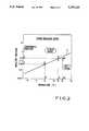
- FIG. 2is a graph showing a vapor-pressure curve of a liquid gas having a vapor pressure higher than the atmospheric pressure
- FIG. 3is a view showing a piping system for explaining a conventional gas supply apparatus.
- FIG. 1shows a piping system for explaining a gas supply apparatus according to an embodiment of the present invention.
- a first control valve 3a mass flow controller 4a, arranged as in a vacuum device 9 of a conventional apparatus, for automatically controlling a gas flow rate, a second control valve 5, and a heater 13a which is wound on a source valve 2, the first control valve 3, the mass flow controller 4a, and a pipe for connecting these components to heat these components are arranged at the outlet of the source valve 2 connected to a bomb 1 filled with a liquid gas.
- a vacuum device 9 connected to the gas supply apparatus 6a through a pipe 7consists of a vacuum vessel 10, a vacuum pump 12, and valves 15 and 16.
- FIG. 2shows a vapor pressure curve of a liquid gas having a vapor pressure higher than the atmospheric pressure.
- a liquid gas having a vapor-pressure characteristic curve X shown in FIG. 2is filled in the bomb 1, and the gas flows into the vacuum vessel 10 evacuated by the vacuum pump 12 of the vacuum device 9.
- the pressure of the gas flowing from the bomb 1 to the mass flow controller 4ais 0.2 atm as obtained by A ⁇ B ⁇ C.
- the gas in the pipe extending from the mass flow controller 4a to the vacuum vessel 10is set in a perfect gas state, the gas need not be heated. Therefore, in installation of the pipe, the same pipe installation and management as those of a normal high-pressure gas pipe can be used.
- the heater 13amay be omitted. In this case, even if the gas is liquefied, since the liquid gas flows into the gas bomb 1 due to its weight, the liquid gas rarely clogs the pipe.
- the mass flow controller 4a for controlling a flow rateis arranged on the gas supply apparatus side, and the temperature of the gas supplied from the valve and the mass flow controller 4a is set to be room temperature.
- the pressure in the pipe 7 extending from the mass flow controller 4a to the vacuum vessel 10is close to but slightly lower than the pressure of the vacuum vessel 10. Even when the temperature in the pipe is decreased, the gas is not liquefied.
- an air conditionermay be arranged in a chamber for incorporating the gas supply apparatus to keep the ambient temperature of the gas supply apparatus to be room temperature.
- a mass flow controller for controlling a flow rateis connected to a gas supply bomb to allow the gas to be supplied to a long pipe at a low pressure, even when the temperature in the pipe is decreased, the gas is not liquefied. Therefore, a gas supply apparatus having the following effects can be obtained. That is, the long pipe need not be wound with a heater, routine maintenance can be easily performed, and installation can be performed at low cost.
Landscapes
- Engineering & Computer Science (AREA)
- Mechanical Engineering (AREA)
- General Engineering & Computer Science (AREA)
- Filling Or Discharging Of Gas Storage Vessels (AREA)
Abstract
Description
Claims (5)
Applications Claiming Priority (2)
| Application Number | Priority Date | Filing Date | Title |
|---|---|---|---|
| JP3-042683[U] | 1991-06-07 | ||
| JP1991042683UJP2567099Y2 (en) | 1991-06-07 | 1991-06-07 | Gas supply device |
Publications (1)
| Publication Number | Publication Date |
|---|---|
| US5279129Atrue US5279129A (en) | 1994-01-18 |
Family
ID=12642832
Family Applications (1)
| Application Number | Title | Priority Date | Filing Date |
|---|---|---|---|
| US07/891,804Expired - Fee RelatedUS5279129A (en) | 1991-06-07 | 1992-06-01 | Gas supply apparatus |
Country Status (2)
| Country | Link |
|---|---|
| US (1) | US5279129A (en) |
| JP (1) | JP2567099Y2 (en) |
Cited By (49)
| Publication number | Priority date | Publication date | Assignee | Title |
|---|---|---|---|---|
| US5470390A (en)* | 1993-05-07 | 1995-11-28 | Teisan Kabushiki Kaisha | Mixed gas supply system with a backup supply system |
| FR2759146A1 (en)* | 1997-02-05 | 1998-08-07 | Air Liquide | Installation for providing working gas, e.g. for manufacture of electronic circuits |
| US5832177A (en)* | 1990-10-05 | 1998-11-03 | Fujitsu Limited | Method for controlling apparatus for supplying steam for ashing process |
| EP0844431A3 (en)* | 1996-11-25 | 1999-04-28 | L'air Liquide, Societe Anonyme Pour L'etude Et L'exploitation Des Procedes Georges Claude | System and method for controlled delivery of liquefied gases |
| US6101316A (en)* | 1998-05-28 | 2000-08-08 | Nihon Shinku Gijutsu Kabushiki Kaisha | Evaporation apparatus, organic material evaporation source, and method of manufacturing thin organic film |
| US6275649B1 (en) | 1998-06-01 | 2001-08-14 | Nihon Shinku Gijutsu Kabushiki Kaisha | Evaporation apparatus |
| US6473564B1 (en) | 2000-01-07 | 2002-10-29 | Nihon Shinku Gijutsu Kabushiki Kaisha | Method of manufacturing thin organic film |
| US20070210260A1 (en)* | 2003-12-12 | 2007-09-13 | Horsky Thomas N | Method And Apparatus For Extending Equipment Uptime In Ion Implantation |
| US20080073559A1 (en)* | 2003-12-12 | 2008-03-27 | Horsky Thomas N | Controlling the flow of vapors sublimated from solids |
| US20080223409A1 (en)* | 2003-12-12 | 2008-09-18 | Horsky Thomas N | Method and apparatus for extending equipment uptime in ion implantation |
| US20090081874A1 (en)* | 2007-09-21 | 2009-03-26 | Cook Kevin S | Method for extending equipment uptime in ion implantation |
| RU2400666C1 (en)* | 2009-01-11 | 2010-09-27 | Физико-технический институт Уральского отделения Российской Академии Наук ФТИ УрО РАН | System of gas puffing |
| US20110314838A1 (en)* | 2009-03-04 | 2011-12-29 | Horiba Stec, Co., Ltd. | Gas supply device |
| US8437833B2 (en) | 2008-10-07 | 2013-05-07 | Bard Access Systems, Inc. | Percutaneous magnetic gastrostomy |
| US8478382B2 (en) | 2008-02-11 | 2013-07-02 | C. R. Bard, Inc. | Systems and methods for positioning a catheter |
| US8512256B2 (en) | 2006-10-23 | 2013-08-20 | Bard Access Systems, Inc. | Method of locating the tip of a central venous catheter |
| US8774907B2 (en) | 2006-10-23 | 2014-07-08 | Bard Access Systems, Inc. | Method of locating the tip of a central venous catheter |
| US8781555B2 (en) | 2007-11-26 | 2014-07-15 | C. R. Bard, Inc. | System for placement of a catheter including a signal-generating stylet |
| US8784336B2 (en) | 2005-08-24 | 2014-07-22 | C. R. Bard, Inc. | Stylet apparatuses and methods of manufacture |
| US8801693B2 (en) | 2010-10-29 | 2014-08-12 | C. R. Bard, Inc. | Bioimpedance-assisted placement of a medical device |
| US8849382B2 (en) | 2007-11-26 | 2014-09-30 | C. R. Bard, Inc. | Apparatus and display methods relating to intravascular placement of a catheter |
| USD724745S1 (en) | 2011-08-09 | 2015-03-17 | C. R. Bard, Inc. | Cap for an ultrasound probe |
| US9125578B2 (en) | 2009-06-12 | 2015-09-08 | Bard Access Systems, Inc. | Apparatus and method for catheter navigation and tip location |
| US9211107B2 (en) | 2011-11-07 | 2015-12-15 | C. R. Bard, Inc. | Ruggedized ultrasound hydrogel insert |
| USD754357S1 (en) | 2011-08-09 | 2016-04-19 | C. R. Bard, Inc. | Ultrasound probe head |
| US9339206B2 (en) | 2009-06-12 | 2016-05-17 | Bard Access Systems, Inc. | Adaptor for endovascular electrocardiography |
| US20160178193A1 (en)* | 2014-12-22 | 2016-06-23 | Horiba Stec, Co., Ltd. | Vaporization system |
| US9445734B2 (en) | 2009-06-12 | 2016-09-20 | Bard Access Systems, Inc. | Devices and methods for endovascular electrography |
| US9456766B2 (en) | 2007-11-26 | 2016-10-04 | C. R. Bard, Inc. | Apparatus for use with needle insertion guidance system |
| US9492097B2 (en) | 2007-11-26 | 2016-11-15 | C. R. Bard, Inc. | Needle length determination and calibration for insertion guidance system |
| US9521961B2 (en) | 2007-11-26 | 2016-12-20 | C. R. Bard, Inc. | Systems and methods for guiding a medical instrument |
| US9532724B2 (en) | 2009-06-12 | 2017-01-03 | Bard Access Systems, Inc. | Apparatus and method for catheter navigation using endovascular energy mapping |
| US9554716B2 (en) | 2007-11-26 | 2017-01-31 | C. R. Bard, Inc. | Insertion guidance system for needles and medical components |
| US9636031B2 (en) | 2007-11-26 | 2017-05-02 | C.R. Bard, Inc. | Stylets for use with apparatus for intravascular placement of a catheter |
| US9649048B2 (en) | 2007-11-26 | 2017-05-16 | C. R. Bard, Inc. | Systems and methods for breaching a sterile field for intravascular placement of a catheter |
| US9681823B2 (en) | 2007-11-26 | 2017-06-20 | C. R. Bard, Inc. | Integrated system for intravascular placement of a catheter |
| US9839372B2 (en) | 2014-02-06 | 2017-12-12 | C. R. Bard, Inc. | Systems and methods for guidance and placement of an intravascular device |
| US9901714B2 (en) | 2008-08-22 | 2018-02-27 | C. R. Bard, Inc. | Catheter assembly including ECG sensor and magnetic assemblies |
| US10046139B2 (en) | 2010-08-20 | 2018-08-14 | C. R. Bard, Inc. | Reconfirmation of ECG-assisted catheter tip placement |
| US10349890B2 (en) | 2015-06-26 | 2019-07-16 | C. R. Bard, Inc. | Connector interface for ECG-based catheter positioning system |
| US10449330B2 (en) | 2007-11-26 | 2019-10-22 | C. R. Bard, Inc. | Magnetic element-equipped needle assemblies |
| US10524691B2 (en) | 2007-11-26 | 2020-01-07 | C. R. Bard, Inc. | Needle assembly including an aligned magnetic element |
| US10639008B2 (en) | 2009-10-08 | 2020-05-05 | C. R. Bard, Inc. | Support and cover structures for an ultrasound probe head |
| US10751509B2 (en) | 2007-11-26 | 2020-08-25 | C. R. Bard, Inc. | Iconic representations for guidance of an indwelling medical device |
| US10820885B2 (en) | 2012-06-15 | 2020-11-03 | C. R. Bard, Inc. | Apparatus and methods for detection of a removable cap on an ultrasound probe |
| US10973584B2 (en) | 2015-01-19 | 2021-04-13 | Bard Access Systems, Inc. | Device and method for vascular access |
| US10992079B2 (en) | 2018-10-16 | 2021-04-27 | Bard Access Systems, Inc. | Safety-equipped connection systems and methods thereof for establishing electrical connections |
| US11000207B2 (en) | 2016-01-29 | 2021-05-11 | C. R. Bard, Inc. | Multiple coil system for tracking a medical device |
| US11103213B2 (en) | 2009-10-08 | 2021-08-31 | C. R. Bard, Inc. | Spacers for use with an ultrasound probe |
Citations (1)
| Publication number | Priority date | Publication date | Assignee | Title |
|---|---|---|---|---|
| US4348873A (en)* | 1977-09-25 | 1982-09-14 | Kabushiki Kaisha Kurio-Medikaru | Apparatus for refrigeration treatment |
Family Cites Families (1)
| Publication number | Priority date | Publication date | Assignee | Title |
|---|---|---|---|---|
| JPH0652553B2 (en)* | 1985-08-19 | 1994-07-06 | アイホン株式会社 | Intercom system for housing complex |
- 1991
- 1991-06-07JPJP1991042683Upatent/JP2567099Y2/ennot_activeExpired - Lifetime
- 1992
- 1992-06-01USUS07/891,804patent/US5279129A/ennot_activeExpired - Fee Related
Patent Citations (1)
| Publication number | Priority date | Publication date | Assignee | Title |
|---|---|---|---|---|
| US4348873A (en)* | 1977-09-25 | 1982-09-14 | Kabushiki Kaisha Kurio-Medikaru | Apparatus for refrigeration treatment |
Non-Patent Citations (2)
| Title |
|---|
| H. B. Bell et al., "Reactive Ion Etching of Aluminum/Silicon in BBr3 /Cl2 and BCl3 /Cl2 Mixtures", J. Electrochem, Soc.: Solid-State Science and Technology May 1988, vol. 135, No. 5, pp. 1184-1191. |
| H. B. Bell et al., Reactive Ion Etching of Aluminum/Silicon in BBr 3 /Cl 2 and BCl 3 /Cl 2 Mixtures , J. Electrochem, Soc.: Solid State Science and Technology May 1988, vol. 135, No. 5, pp. 1184 1191.* |
Cited By (94)
| Publication number | Priority date | Publication date | Assignee | Title |
|---|---|---|---|---|
| US5832177A (en)* | 1990-10-05 | 1998-11-03 | Fujitsu Limited | Method for controlling apparatus for supplying steam for ashing process |
| US5470390A (en)* | 1993-05-07 | 1995-11-28 | Teisan Kabushiki Kaisha | Mixed gas supply system with a backup supply system |
| EP0844431A3 (en)* | 1996-11-25 | 1999-04-28 | L'air Liquide, Societe Anonyme Pour L'etude Et L'exploitation Des Procedes Georges Claude | System and method for controlled delivery of liquefied gases |
| US6076359A (en)* | 1996-11-25 | 2000-06-20 | American Air Liquide Inc. | System and method for controlled delivery of liquified gases |
| FR2759146A1 (en)* | 1997-02-05 | 1998-08-07 | Air Liquide | Installation for providing working gas, e.g. for manufacture of electronic circuits |
| US6101316A (en)* | 1998-05-28 | 2000-08-08 | Nihon Shinku Gijutsu Kabushiki Kaisha | Evaporation apparatus, organic material evaporation source, and method of manufacturing thin organic film |
| US6507698B2 (en) | 1998-06-01 | 2003-01-14 | Nihon Shinku Gijutsu Kabushiki Kaisha | Evaporation apparatus, organic material evaporation source, and method of manufacturing thin organic film |
| US6275649B1 (en) | 1998-06-01 | 2001-08-14 | Nihon Shinku Gijutsu Kabushiki Kaisha | Evaporation apparatus |
| US6473564B1 (en) | 2000-01-07 | 2002-10-29 | Nihon Shinku Gijutsu Kabushiki Kaisha | Method of manufacturing thin organic film |
| US7820981B2 (en) | 2003-12-12 | 2010-10-26 | Semequip, Inc. | Method and apparatus for extending equipment uptime in ion implantation |
| US20070241689A1 (en)* | 2003-12-12 | 2007-10-18 | Horsky Thomas N | Method and apparatus for extending equipment uptime in ion implantation |
| US20080047607A1 (en)* | 2003-12-12 | 2008-02-28 | Horsky Thomas N | Controlling The Flow Of Vapors Sublimated From Solids |
| US20080073559A1 (en)* | 2003-12-12 | 2008-03-27 | Horsky Thomas N | Controlling the flow of vapors sublimated from solids |
| US20080121811A1 (en)* | 2003-12-12 | 2008-05-29 | Horsky Thomas N | Method and apparatus for extending equipment uptime in ion implantation |
| US20080223409A1 (en)* | 2003-12-12 | 2008-09-18 | Horsky Thomas N | Method and apparatus for extending equipment uptime in ion implantation |
| US20070210260A1 (en)* | 2003-12-12 | 2007-09-13 | Horsky Thomas N | Method And Apparatus For Extending Equipment Uptime In Ion Implantation |
| US7629590B2 (en) | 2003-12-12 | 2009-12-08 | Semequip, Inc. | Method and apparatus for extending equipment uptime in ion implantation |
| US7723700B2 (en) | 2003-12-12 | 2010-05-25 | Semequip, Inc. | Controlling the flow of vapors sublimated from solids |
| US11207496B2 (en) | 2005-08-24 | 2021-12-28 | C. R. Bard, Inc. | Stylet apparatuses and methods of manufacture |
| US10004875B2 (en) | 2005-08-24 | 2018-06-26 | C. R. Bard, Inc. | Stylet apparatuses and methods of manufacture |
| US8784336B2 (en) | 2005-08-24 | 2014-07-22 | C. R. Bard, Inc. | Stylet apparatuses and methods of manufacture |
| US8858455B2 (en) | 2006-10-23 | 2014-10-14 | Bard Access Systems, Inc. | Method of locating the tip of a central venous catheter |
| US9833169B2 (en) | 2006-10-23 | 2017-12-05 | Bard Access Systems, Inc. | Method of locating the tip of a central venous catheter |
| US8512256B2 (en) | 2006-10-23 | 2013-08-20 | Bard Access Systems, Inc. | Method of locating the tip of a central venous catheter |
| US8774907B2 (en) | 2006-10-23 | 2014-07-08 | Bard Access Systems, Inc. | Method of locating the tip of a central venous catheter |
| US9345422B2 (en) | 2006-10-23 | 2016-05-24 | Bard Acess Systems, Inc. | Method of locating the tip of a central venous catheter |
| US9265443B2 (en) | 2006-10-23 | 2016-02-23 | Bard Access Systems, Inc. | Method of locating the tip of a central venous catheter |
| US7875125B2 (en) | 2007-09-21 | 2011-01-25 | Semequip, Inc. | Method for extending equipment uptime in ion implantation |
| US20090081874A1 (en)* | 2007-09-21 | 2009-03-26 | Cook Kevin S | Method for extending equipment uptime in ion implantation |
| US10524691B2 (en) | 2007-11-26 | 2020-01-07 | C. R. Bard, Inc. | Needle assembly including an aligned magnetic element |
| US10165962B2 (en) | 2007-11-26 | 2019-01-01 | C. R. Bard, Inc. | Integrated systems for intravascular placement of a catheter |
| US11779240B2 (en) | 2007-11-26 | 2023-10-10 | C. R. Bard, Inc. | Systems and methods for breaching a sterile field for intravascular placement of a catheter |
| US11707205B2 (en) | 2007-11-26 | 2023-07-25 | C. R. Bard, Inc. | Integrated system for intravascular placement of a catheter |
| US11529070B2 (en) | 2007-11-26 | 2022-12-20 | C. R. Bard, Inc. | System and methods for guiding a medical instrument |
| US11134915B2 (en) | 2007-11-26 | 2021-10-05 | C. R. Bard, Inc. | System for placement of a catheter including a signal-generating stylet |
| US11123099B2 (en) | 2007-11-26 | 2021-09-21 | C. R. Bard, Inc. | Apparatus for use with needle insertion guidance system |
| US10966630B2 (en) | 2007-11-26 | 2021-04-06 | C. R. Bard, Inc. | Integrated system for intravascular placement of a catheter |
| US10849695B2 (en) | 2007-11-26 | 2020-12-01 | C. R. Bard, Inc. | Systems and methods for breaching a sterile field for intravascular placement of a catheter |
| US10751509B2 (en) | 2007-11-26 | 2020-08-25 | C. R. Bard, Inc. | Iconic representations for guidance of an indwelling medical device |
| US8781555B2 (en) | 2007-11-26 | 2014-07-15 | C. R. Bard, Inc. | System for placement of a catheter including a signal-generating stylet |
| US10602958B2 (en) | 2007-11-26 | 2020-03-31 | C. R. Bard, Inc. | Systems and methods for guiding a medical instrument |
| US10449330B2 (en) | 2007-11-26 | 2019-10-22 | C. R. Bard, Inc. | Magnetic element-equipped needle assemblies |
| US10342575B2 (en) | 2007-11-26 | 2019-07-09 | C. R. Bard, Inc. | Apparatus for use with needle insertion guidance system |
| US9456766B2 (en) | 2007-11-26 | 2016-10-04 | C. R. Bard, Inc. | Apparatus for use with needle insertion guidance system |
| US9492097B2 (en) | 2007-11-26 | 2016-11-15 | C. R. Bard, Inc. | Needle length determination and calibration for insertion guidance system |
| US9521961B2 (en) | 2007-11-26 | 2016-12-20 | C. R. Bard, Inc. | Systems and methods for guiding a medical instrument |
| US9526440B2 (en) | 2007-11-26 | 2016-12-27 | C.R. Bard, Inc. | System for placement of a catheter including a signal-generating stylet |
| US10238418B2 (en) | 2007-11-26 | 2019-03-26 | C. R. Bard, Inc. | Apparatus for use with needle insertion guidance system |
| US9549685B2 (en) | 2007-11-26 | 2017-01-24 | C. R. Bard, Inc. | Apparatus and display methods relating to intravascular placement of a catheter |
| US9554716B2 (en) | 2007-11-26 | 2017-01-31 | C. R. Bard, Inc. | Insertion guidance system for needles and medical components |
| US9636031B2 (en) | 2007-11-26 | 2017-05-02 | C.R. Bard, Inc. | Stylets for use with apparatus for intravascular placement of a catheter |
| US9649048B2 (en) | 2007-11-26 | 2017-05-16 | C. R. Bard, Inc. | Systems and methods for breaching a sterile field for intravascular placement of a catheter |
| US9681823B2 (en) | 2007-11-26 | 2017-06-20 | C. R. Bard, Inc. | Integrated system for intravascular placement of a catheter |
| US10231753B2 (en) | 2007-11-26 | 2019-03-19 | C. R. Bard, Inc. | Insertion guidance system for needles and medical components |
| US8849382B2 (en) | 2007-11-26 | 2014-09-30 | C. R. Bard, Inc. | Apparatus and display methods relating to intravascular placement of a catheter |
| US10105121B2 (en) | 2007-11-26 | 2018-10-23 | C. R. Bard, Inc. | System for placement of a catheter including a signal-generating stylet |
| US9999371B2 (en) | 2007-11-26 | 2018-06-19 | C. R. Bard, Inc. | Integrated system for intravascular placement of a catheter |
| US8478382B2 (en) | 2008-02-11 | 2013-07-02 | C. R. Bard, Inc. | Systems and methods for positioning a catheter |
| US8971994B2 (en) | 2008-02-11 | 2015-03-03 | C. R. Bard, Inc. | Systems and methods for positioning a catheter |
| US9901714B2 (en) | 2008-08-22 | 2018-02-27 | C. R. Bard, Inc. | Catheter assembly including ECG sensor and magnetic assemblies |
| US11027101B2 (en) | 2008-08-22 | 2021-06-08 | C. R. Bard, Inc. | Catheter assembly including ECG sensor and magnetic assemblies |
| US9907513B2 (en) | 2008-10-07 | 2018-03-06 | Bard Access Systems, Inc. | Percutaneous magnetic gastrostomy |
| US8437833B2 (en) | 2008-10-07 | 2013-05-07 | Bard Access Systems, Inc. | Percutaneous magnetic gastrostomy |
| RU2400666C1 (en)* | 2009-01-11 | 2010-09-27 | Физико-технический институт Уральского отделения Российской Академии Наук ФТИ УрО РАН | System of gas puffing |
| US20110314838A1 (en)* | 2009-03-04 | 2011-12-29 | Horiba Stec, Co., Ltd. | Gas supply device |
| US9157578B2 (en)* | 2009-03-04 | 2015-10-13 | Horiba Stec, Co., Ltd. | Gas supply device |
| US10231643B2 (en) | 2009-06-12 | 2019-03-19 | Bard Access Systems, Inc. | Apparatus and method for catheter navigation and tip location |
| US9532724B2 (en) | 2009-06-12 | 2017-01-03 | Bard Access Systems, Inc. | Apparatus and method for catheter navigation using endovascular energy mapping |
| US10271762B2 (en) | 2009-06-12 | 2019-04-30 | Bard Access Systems, Inc. | Apparatus and method for catheter navigation using endovascular energy mapping |
| US9445734B2 (en) | 2009-06-12 | 2016-09-20 | Bard Access Systems, Inc. | Devices and methods for endovascular electrography |
| US11419517B2 (en) | 2009-06-12 | 2022-08-23 | Bard Access Systems, Inc. | Apparatus and method for catheter navigation using endovascular energy mapping |
| US10912488B2 (en) | 2009-06-12 | 2021-02-09 | Bard Access Systems, Inc. | Apparatus and method for catheter navigation and tip location |
| US9125578B2 (en) | 2009-06-12 | 2015-09-08 | Bard Access Systems, Inc. | Apparatus and method for catheter navigation and tip location |
| US9339206B2 (en) | 2009-06-12 | 2016-05-17 | Bard Access Systems, Inc. | Adaptor for endovascular electrocardiography |
| US11103213B2 (en) | 2009-10-08 | 2021-08-31 | C. R. Bard, Inc. | Spacers for use with an ultrasound probe |
| US11998386B2 (en) | 2009-10-08 | 2024-06-04 | C. R. Bard, Inc. | Support and cover structures for an ultrasound probe head |
| US10639008B2 (en) | 2009-10-08 | 2020-05-05 | C. R. Bard, Inc. | Support and cover structures for an ultrasound probe head |
| US10046139B2 (en) | 2010-08-20 | 2018-08-14 | C. R. Bard, Inc. | Reconfirmation of ECG-assisted catheter tip placement |
| US8801693B2 (en) | 2010-10-29 | 2014-08-12 | C. R. Bard, Inc. | Bioimpedance-assisted placement of a medical device |
| US9415188B2 (en) | 2010-10-29 | 2016-08-16 | C. R. Bard, Inc. | Bioimpedance-assisted placement of a medical device |
| USD754357S1 (en) | 2011-08-09 | 2016-04-19 | C. R. Bard, Inc. | Ultrasound probe head |
| USD724745S1 (en) | 2011-08-09 | 2015-03-17 | C. R. Bard, Inc. | Cap for an ultrasound probe |
| US9211107B2 (en) | 2011-11-07 | 2015-12-15 | C. R. Bard, Inc. | Ruggedized ultrasound hydrogel insert |
| US10820885B2 (en) | 2012-06-15 | 2020-11-03 | C. R. Bard, Inc. | Apparatus and methods for detection of a removable cap on an ultrasound probe |
| US9839372B2 (en) | 2014-02-06 | 2017-12-12 | C. R. Bard, Inc. | Systems and methods for guidance and placement of an intravascular device |
| US10863920B2 (en) | 2014-02-06 | 2020-12-15 | C. R. Bard, Inc. | Systems and methods for guidance and placement of an intravascular device |
| US9982883B2 (en)* | 2014-12-22 | 2018-05-29 | Horiba Stec, Co., Ltd. | Vaporization system |
| US20160178193A1 (en)* | 2014-12-22 | 2016-06-23 | Horiba Stec, Co., Ltd. | Vaporization system |
| US10973584B2 (en) | 2015-01-19 | 2021-04-13 | Bard Access Systems, Inc. | Device and method for vascular access |
| US10349890B2 (en) | 2015-06-26 | 2019-07-16 | C. R. Bard, Inc. | Connector interface for ECG-based catheter positioning system |
| US11026630B2 (en) | 2015-06-26 | 2021-06-08 | C. R. Bard, Inc. | Connector interface for ECG-based catheter positioning system |
| US11000207B2 (en) | 2016-01-29 | 2021-05-11 | C. R. Bard, Inc. | Multiple coil system for tracking a medical device |
| US11621518B2 (en) | 2018-10-16 | 2023-04-04 | Bard Access Systems, Inc. | Safety-equipped connection systems and methods thereof for establishing electrical connections |
| US10992079B2 (en) | 2018-10-16 | 2021-04-27 | Bard Access Systems, Inc. | Safety-equipped connection systems and methods thereof for establishing electrical connections |
Also Published As
| Publication number | Publication date |
|---|---|
| JP2567099Y2 (en) | 1998-03-30 |
| JPH0525099U (en) | 1993-04-02 |
Similar Documents
| Publication | Publication Date | Title |
|---|---|---|
| US5279129A (en) | Gas supply apparatus | |
| CN100593093C (en) | Device for supplying gaseous fuel to an energy generating device of a ship and method for its regulation | |
| US5678411A (en) | Liquefied gas supply system | |
| US11384903B2 (en) | Cryogenic fluid storage tank | |
| CN105531526B (en) | System for cryogen fuel to be delivered to fuel tank under predetermined saturation pressure | |
| US5467603A (en) | High-pressure gas supply installation | |
| WO2002095797A3 (en) | Gas delivery at high flow rates | |
| IE61753B1 (en) | Quench expansion value refrigeration circuit | |
| US6470690B1 (en) | Method and apparatus for supplying vaporized gas on consumer demand | |
| JPH05324094A (en) | Liquid pressure controller | |
| US5231842A (en) | Refrigerant handling system with liquid refrigerant and multiple refrigerant capabilities | |
| CN113227678A (en) | Cooling system | |
| US6330805B1 (en) | Method of operating a refrigerating unit with a refrigerant fluid circuit | |
| KR101686910B1 (en) | High Pressure Pump Pressurizing System and Method for LNG Regasification System | |
| JPH0429197Y2 (en) | ||
| JP2002188798A (en) | Cryogenic tank equipment | |
| AU633766B2 (en) | Refrigerant handling system with liquid refrigerant and multiple refrigerant capabilities | |
| US6578365B2 (en) | Method and system for supplying vaporized gas on consumer demand | |
| KR200249993Y1 (en) | Liquefied petroleum gas supply system | |
| JP2724774B2 (en) | Decompression evaporative cooling equipment | |
| JPH05306890A (en) | Vaporizer | |
| JP7725524B2 (en) | Natural gas supply system and operation method when restarting operation of the natural gas supply system | |
| JP2572771Y2 (en) | Operation control device for gas vaporization equipment | |
| JPH07151394A (en) | Refrigerator | |
| JPH0633862B2 (en) | Liquefied carbon dioxide vaporization supply device |
Legal Events
| Date | Code | Title | Description |
|---|---|---|---|
| AS | Assignment | Owner name:NEC CORPORATION, JAPAN Free format text:ASSIGNMENT OF ASSIGNORS INTEREST.;ASSIGNOR:ITO, ATSUSHI;REEL/FRAME:006141/0170 Effective date:19920522 | |
| FEPP | Fee payment procedure | Free format text:PAYOR NUMBER ASSIGNED (ORIGINAL EVENT CODE: ASPN); ENTITY STATUS OF PATENT OWNER: LARGE ENTITY | |
| FEPP | Fee payment procedure | Free format text:PAYER NUMBER DE-ASSIGNED (ORIGINAL EVENT CODE: RMPN); ENTITY STATUS OF PATENT OWNER: LARGE ENTITY Free format text:PAYOR NUMBER ASSIGNED (ORIGINAL EVENT CODE: ASPN); ENTITY STATUS OF PATENT OWNER: LARGE ENTITY | |
| FPAY | Fee payment | Year of fee payment:4 | |
| FEPP | Fee payment procedure | Free format text:PAYER NUMBER DE-ASSIGNED (ORIGINAL EVENT CODE: RMPN); ENTITY STATUS OF PATENT OWNER: LARGE ENTITY Free format text:PAYOR NUMBER ASSIGNED (ORIGINAL EVENT CODE: ASPN); ENTITY STATUS OF PATENT OWNER: LARGE ENTITY | |
| FPAY | Fee payment | Year of fee payment:8 | |
| AS | Assignment | Owner name:NEC ELECTRONICS CORPORATION, JAPAN Free format text:ASSIGNMENT OF ASSIGNORS INTEREST;ASSIGNOR:NEC CORPORATION;REEL/FRAME:013758/0440 Effective date:20021101 | |
| REMI | Maintenance fee reminder mailed | ||
| LAPS | Lapse for failure to pay maintenance fees | ||
| STCH | Information on status: patent discontinuation | Free format text:PATENT EXPIRED DUE TO NONPAYMENT OF MAINTENANCE FEES UNDER 37 CFR 1.362 | |
| FP | Lapsed due to failure to pay maintenance fee | Effective date:20060118 |