US5277730A - Methods of recoating spliced lengths of optical fibers - Google Patents
Methods of recoating spliced lengths of optical fibersDownload PDFInfo
- Publication number
- US5277730A US5277730AUS07/821,523US82152392AUS5277730AUS 5277730 AUS5277730 AUS 5277730AUS 82152392 AUS82152392 AUS 82152392AUS 5277730 AUS5277730 AUS 5277730A
- Authority
- US
- United States
- Prior art keywords
- coating material
- optical fiber
- recoating
- end portion
- spliced
- Prior art date
- Legal status (The legal status is an assumption and is not a legal conclusion. Google has not performed a legal analysis and makes no representation as to the accuracy of the status listed.)
- Expired - Lifetime
Links
Images


Classifications
- G—PHYSICS
- G02—OPTICS
- G02B—OPTICAL ELEMENTS, SYSTEMS OR APPARATUS
- G02B6/00—Light guides; Structural details of arrangements comprising light guides and other optical elements, e.g. couplings
- G02B6/24—Coupling light guides
- G02B6/255—Splicing of light guides, e.g. by fusion or bonding
- G02B6/2558—Reinforcement of splice joint
- G—PHYSICS
- G02—OPTICS
- G02B—OPTICAL ELEMENTS, SYSTEMS OR APPARATUS
- G02B6/00—Light guides; Structural details of arrangements comprising light guides and other optical elements, e.g. couplings
- G02B6/24—Coupling light guides
- G02B6/36—Mechanical coupling means
- G02B6/38—Mechanical coupling means having fibre to fibre mating means
- G02B6/3801—Permanent connections, i.e. wherein fibres are kept aligned by mechanical means
Definitions
- This inventionrelates to methods of recoating spliced lengths of optical fibers. More particularly, it relates to the recoating of a fusion bonded optical fiber splice and portions of optical fibers adjacent to the splice which provides substantially improved integrity over recoated splices made in accordance with the prior art.
- optical communicationsinvolving the use of optical fibers has grown at an unprecedented pace.
- an optical fiberhas a diameter on the order of 125 microns, for example, and is covered with a coating material which increases the outer diameter of the coated fiber to about 250 microns, for example.
- Optical cablesmay comprise a plurality of these optical fibers which are stranded together or which are assembled in planar arrays which are referred to as ribbons.
- a method of recoating spliced end portions of optical fibersis disclosed in U.S. Pat. No. 4,410,561 which issued on Oct. 18, 1983 in the name of A. C. Hart, Jr.
- the methodinvolves placing the spliced fiber end portions from which the original coating material has been removed and adjacent portions within a cavity in the form of a groove in a split mold.
- the effective diameter of the grooveis somewhat greater than that of the remaining coated portion of each fiber.
- the fibersare positioned so that only portions of the coated portions of the fibers touch the surface which defines the groove, while the vulnerable, uncoated spliced end portions of the fibers remain suspended and do not contact the groove surface.
- the moldis covered to enclose the groove and a suitable curable coating material is injected into the groove to recoat the bared, spliced fiber end portions.
- the recoating materialcontacts the adjacent originally coated portions of the spliced fibers along substantially radial planes exposed when the original coating material was removed from the end portions and along overlapping portions of the outer surface of the original coating material adjacent to the radial planes.
- the coating materialis then cured to yield a recoated splice section with a transverse cross section which is larger than that of the optical fiber having the original coating material thereon.
- This molding processprovides a recoated splice; however, steps must be taken to avoid an undesirable number of residual bubbles in the recoating material.
- the existence of bubblesmay lead to stress concentrations when the fiber is handled subsequently. This is particularly undesirable in underwater cables where splices are inaccessible and under stress for many years.
- optical fibersfor tethered vehicles.
- an optical fiber which is wound on a payoff device and connected to a guidance systemis payed off as the vehicle is moved.
- the payoff devicecontains a length of precision wound optical fiber.
- the winding of the optical fiber on the payoff devicemust be accomplished in a precision manner. Otherwise, payoff could be disrupted. It has been found that it is difficult to wind a precision package with recoated splices which are made by present techniques. If the cross section of the recoated portion transverse of the longitudinal axis of the optical fiber is not the same as that of the optical fiber as originally coated, the winding pattern on the payoff device in all likelihood is not uniform. This will cause problems in fiber payoff following the launch of the tethered vehicle.
- a recoated optical fiber splicewhich may be used in providing a relatively long length of optical fiber for use in guiding a tethered vehicle, for example.
- Such a recoated splicemust be implemented easily, must have the same transverse cross section as that of the original coated optical fiber and must have integrity of adhesion of the recoating material to the original coating material over a period of time.
- the sought after methods which are to be used to recoat spliced end portions of optical fiberspreferably are such that the formation of bubbles is avoided substantially.
- a first length of optical fiberis fusion bonded to a second length of optical fiber.
- each length of optical fiberPrior to bonding, each length of optical fiber is prepared for splicing. This is accomplished by chemically removing coating material from an end portion of each length of the fiber. The coating material is removed so as to leave a bared portion of optical fiber adjacent to the end of the end portion of each optical fiber and so as to leave a tapered length of the original coating material extending from the bared portion to the portion of the optical fiber adjacent to the end portion. In this way, an increased length of surface is provided to become the interface between the original coating material and the recoating material.
- the coating material on end portions of the lengths of each of two optical fibersis removed to leave a bared portion and a portion on which the coating material is conically shaped.
- the prepared end portions which have been spliced togetherare positioned in a passageway of a fixture with original coated portions of the lengths adjacent to the end portions being held in opposed vacuum chucks at opposite ends of the fixture.
- An injection portcommunicates a supply of a curable recoating material with the passageway.
- the passagewayis formed in a mold block of material which is transparent to radiation used to cure the recoating material.
- the mold block of materialis supported on a metallic pedestal. Along an upper surface of the pedestal is provided a trough which is in alignment with the passageway and spaced therefrom and which includes a polished reflective surface.
- the methods of this inventionassure that the recoating material which covers the spliced portions of the lengths of optical fibers are cured uniformly.
- a curable recoating materialAfter a curable recoating material has been injected through the port into the passageway and caused to encapsulate the bared and tapered portions of the end portions, it is cured by exposing it to suitable radiation.
- the trough in the metallic pedestalhas a transverse cross section which is parabolic.
- the passagewayis positioned at the focal point of the parabolic cross section of the trough so that radiation extending past the optical fiber is reflected by the wall of the trough and caused to engage the peripheral portion of the optical fiber which is not exposed directly to the radiation. As a result, the entire periphery of the optical fiber portions in the passageway is cured uniformly.
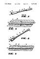
- FIG. 1is a perspective view of spliced end portions of two lengths of optical fibers which have been prepared in accordance with this invention to receive a recoating material;
- FIG. 2is a perspective view of end portions of lengths of optical fiber which have been prepared for recoating in accordance with prior art methods and apparatus;
- FIG. 3is a side elevational view of one of the end portions of FIG. 2 after a recoating material has been applied thereover;
- FIG. 4is a side elevational view of one of the spliced end portions of FIG. 1 after a recoating material has been applied thereover;
- FIG. 5is a schematic view of an apparatus for removing coating material from a portion of the length of an optical fiber
- FIG. 6is a perspective view of an apparatus for recoating spliced end portions of two lengths of optical fibers
- FIG. 7is a perspective view of a fixture of the apparatus of FIG. 6 which may be used to support spliced end portions of lengths of optical fibers for recoating in accordance with this invention
- FIG. 8is a perspective view of a prior art fixture for supporting spliced end portions of optical fibers to be recoated
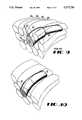
- FIG. 9is a perspective view of spliced lengths of optical fiber wound on a spool, the spliced portion of which has been recoated by prior art methods.
- FIG. 10is a perspective view of spliced lengths of optical fiber wound on a spool, the spliced portion shown having been recoated in accordance with the methods of this invention.
- each of the optical fibersincludes an optical fiber 36 having a coating material 38 applied thereon (see FIG. 1).
- the optical fiber 36includes a core and a cladding.
- An outer diameter of the coated optical fiberis on the order of 250 microns.
- Each end portion 30has a length of about 0.5 inch.
- the spliced end portions 30--30are recoated in accordance with the methods of this invention.
- FIG. 2Typical spliced end portions of optical fiber lengths prior to recoating appear as shown in FIG. 2.
- a coating material 40has been removed from an end portion 42 of each of two optical fibers 44 and 45 which have been spliced together to form a juncture 46.
- the portion of the coating material that has been removedis generally in the shape of a cylindrical tube or sleeve.
- An exposed end face 47 of the coating materiallies generally in a plane which generally is normal to a longitudinal axis 48 of the optical fiber (see FIG. 3).
- a portion 49 of a recoating materialextends past the radial end face plane 47 of the end portion 42 of the optical fiber and overlaps a portion of the original coating material (see FIG. 3). This is done in order to provide sufficient interfacial area between the original coating material and the recoating material to insure the integrity of the coating and recoating materials along the interface therebetween over a period of time.
- the interface between the recoating material 49 and the original coating material without the overlapis not much greater than the cross-sectional annular area of the original coating material.
- the opportunity for adhesion between the original coating and recoating materialsis somewhat limited.
- the overlapped portionis additive to this, but this causes the cross section of the recoated end portion of the optical fiber transverse to the longitudinal axis of the optical fiber to exceed that of the optical fiber with the original coating material thereon.
- each length of optical fiberhas a generally truncated conical shape.
- the original coating materialincreases from a transverse cross section substantially equal to the transverse cross section of the uncoated clad optical fiber of the bared portion 50 to the transverse cross section of the original coated optical fiber.
- the distance from the juncture 35 to the beginning of the tapered portion 52i.e. the length of the bared portion 50, is about 0.25 inch or more and the length of the tapered portion of the original coating material is equal at least to the product of three and the largest dimension of a transverse cross section of a coated optical fiber but does not exceed a value of about 0.25 inch.
- Such a configuration of the coating material remaining after strippingis highly advantageous during recoating.
- a recoating material 51abuts the original coating material along an interface which is substantially larger than that of FIG. 3.
- the increased interfacial contact of the recoating material 51 and the original coating material 38obviates the need for overlap as used in FIG. 3.
- the transverse cross section of the recoated end portions 30--30may be held to be substantially the same as that of the optical fiber having the original coating material 38 thereon.
- the cross section of the coated optical fiber along portions having the original coating material 38 thereon and along those portions which have been recoatedis substantially constant.
- PreparationPrior to the fusion bonding and recoating steps of providing a spliced length of optical fiber, the end portions 30--30 of two lengths of optical fiber must be prepared. Preparation includes the complete removal of the original coating material from a portion 50 of the end portion 30. Preparation also includes the removal of a portion which is contiguous to the portion 50 (see FIG. 1) and which has a transverse cross section that decreases in a direction from the portion 50 to the coated optical fiber adjacent to the end portion 30.
- FIG. 5there is shown a holder 53 for holding an optical fiber length 32 above a container 55 of a suitable liquid material such as an acid which may be used to remove coating material from an end portion 30 of an optical fiber to provide the configuration shown in FIG. 1.
- the holder 53is adapted to be moved vertically reciprocally by turning a cam 57.
- An operatormounts the optical fiber 32 in the holder 53 with a portion of the optical fiber contiguous to an end of the optical fiber being immersed in the liquid material in the container 55. This causes the coating material 38 to be removed completely from that portion which is immersed to form a bared portion. Then the operator causes the cam 57 to be turned. As a result, the portion of the end portion 30 of the optical fiber which is adjacent to the bared portion is moved into and out of the container 55 in one or more cycles to remove the coating material partially therefrom to form the tapered portion 52 shown in FIG. 1.
- the configuration of the tapered portion 52is a function of the temperature of the liquid material in the container 55 as well as the cycle time and the configuration of the cam. Subsequently, the operator causes the bared portion to be broken to provide the bared portion 50 having a desired length.
- end portions of two lengths of optical fibers having the coating material thereon removed as described hereinaboveare spliced together by fusion bonding for example.
- the spliced end portions 30--30are now ready to be recoated.
- FIG. 6Shown in FIG. 6 is an apparatus designated generally by the numeral 60 for recoating the spliced together ends of the lengths of optical fibers.
- the apparatus 60includes a base 62 which includes two ways 64 and 66 spaced along a longitudinal axis of the base. Mounted in each of the ways 64 and 66 is a vacuum chuck 68.
- Each chuck 68includes a groove 71 which extends generally parallel to the longitudinal axis of the base.
- Each of the grooves 71--71has a transverse cross section such that it is capable of holding a length of coated optical fiber. Further, the wall of each of the grooves 71--71 is connected to a source of vacuum (not shown)to hold a coated optical fiber in the groove during the recoating process.
- a center portion 73 of the base 60is raised somewhat over adjacent portions.
- the center portion 73includes a longitudinally extending trough 75 which in transverse cross section has a parabolic configuration.
- This trough 75is referred to as a reflective chamber and typically is milled in a base which is made of aluminum.
- the surface of the trough 75is polished.
- the mold block 80Supported on the center portion 73 is a mold block 80 (see FIGS. 6 and 7).
- the mold block 80includes a longitudinal extending groove 82 which is adapted to hold the spliced end portions of two lengths of optical fibers.
- Projecting upwardly from two corners of the mold block 80are two alignment pins 84--84.
- the alignment pins 84--84are used to align a top mold block 90 with the mold block 80.
- the mold blocksare made from a material which is transparent to ultraviolet (UV) radiation such as Plexiglas® UV transparent material or equivalent resin material or quartz, for example.
- the top mold block 90also includes a longitudinally extending groove 92 which is adapted to cooperate with the groove 82 in the mold block 80 to provide a passageway 93 to enclose the spliced end portions of the two lengths of optical fibers. Further, the top mold block 90 is secured to the mold block 80 to provide a close fitting groove for those end portions by four bolts 94--94, or other suitable clamping means.
- passageway 93communicates with an injection nozzle 96 (see FIG. 6).
- the injection nozzle 96is connected to a supply of recoating material which preferably is the same material which was used to coat the drawn fiber.
- a materialmay be a UV curable acrylate material, for example.
- Portions of the spliced lengths 32 and 33 of the optical fibers adjacent to the end portions 30--30are caused to be received in the grooves 71--71 in the chucks 68--68. Vacuum is applied to hold those portions during the recoating step. With the portions of the lengths of optical fibers held in the vacuum chucks 68--68, the lengths of the optical fiber which are spliced together are disposed in the passageway 93 formed by the cooperating grooves in the top mold block 90 and the mold block 80.
- the passageway 93 formed by the grooves in the top mold 90 and in the mold 80is aligned with the reflective chamber 75.
- the spatial relationship of the passageway 93 and the reflective chamber 75is such that the passageway is disposed at the focal point of the parabolic configuration of the reflective chamber.
- the arrangement which is shown in FIG. 7assures substantially uniformity of cure in the recoating material.
- the UV energy radiating past the optical fiber end portions 30--30 and contacting the parabolic surfaceis reflected. Because the recoated portions are disposed at the focal point of the parabolic reflecting surface, the reflected radiation contacts those portions of the periphery of the recoating material which are not exposed directly to the emitted radiation, thereby ensuring the uniformity of cure.
- the resulting productis a relatively long length of optical fiber which has a substantially constant cross section transverse to the longitudinal axis of the optical fiber.
- the cross section of the recoated spliced portions transverse to the longitudinal axis of the optical fiberare substantially equal to that of the unspliced end portions.
- This equivalence of transverse cross sectionis advantageous particularly in the winding of the fiber on a spool or other payout device.
- the transverse cross section of a spliced portionis larger than that of the unspliced portions.
- the enlarged splicecauses unwanted bulging of the portion of fiber directly covering the splice, as can be seen by portions 104,105, 106, and 107, for example in FIG. 9. This may result in snags during payoff as portions of outer convolutions become caught in spacing between the spliced portions and convolutions adjacent thereto.
- spliced portions recoated by the methods and apparatus of this inventiona precise winding pattern is achievable without any spacing between convolutions which include the recoated portions and those that do not (see FIG. 10).
- the recoating technique of this inventionalso helps to avoid the occurrence of bubbles adjacent to the interface. Bubbles tend to become entrapped at the interface between the original coating material and the recoating material. Also, when the recoating material is applied, it contracts and tends to pull bubbles outwardly from the original coating material into the interface. The existence of bubbles is unwanted, particularly at the interface, because of possible adverse affects on the adhesion level across the interface. It has been found that because of the lengthened interface provided by the methods and apparatus of this invention, any bubbles tend to be moved outwardly toward the outer surface of the optical fiber and are not residual in the recoated splice portions.
Landscapes
- Physics & Mathematics (AREA)
- General Physics & Mathematics (AREA)
- Optics & Photonics (AREA)
- Engineering & Computer Science (AREA)
- Plasma & Fusion (AREA)
- Mechanical Coupling Of Light Guides (AREA)
Abstract
Description
Claims (6)
Priority Applications (1)
| Application Number | Priority Date | Filing Date | Title |
|---|---|---|---|
| US07/821,523US5277730A (en) | 1987-12-16 | 1992-04-07 | Methods of recoating spliced lengths of optical fibers |
Applications Claiming Priority (4)
| Application Number | Priority Date | Filing Date | Title |
|---|---|---|---|
| US07/133,579US4865411A (en) | 1987-12-16 | 1987-12-16 | Recoated spliced lengths of optical fibers |
| US37678189A | 1989-07-07 | 1989-07-07 | |
| US65789391A | 1991-02-02 | 1991-02-02 | |
| US07/821,523US5277730A (en) | 1987-12-16 | 1992-04-07 | Methods of recoating spliced lengths of optical fibers |
Related Parent Applications (1)
| Application Number | Title | Priority Date | Filing Date |
|---|---|---|---|
| US65789391AContinuation | 1987-12-16 | 1991-02-02 |
Publications (1)
| Publication Number | Publication Date |
|---|---|
| US5277730Atrue US5277730A (en) | 1994-01-11 |
Family
ID=27495039
Family Applications (1)
| Application Number | Title | Priority Date | Filing Date |
|---|---|---|---|
| US07/821,523Expired - LifetimeUS5277730A (en) | 1987-12-16 | 1992-04-07 | Methods of recoating spliced lengths of optical fibers |
Country Status (1)
| Country | Link |
|---|---|
| US (1) | US5277730A (en) |
Cited By (28)
| Publication number | Priority date | Publication date | Assignee | Title |
|---|---|---|---|---|
| US5595692A (en)* | 1994-09-13 | 1997-01-21 | United Technologies Corporation | Method of repairing resin impregnated articles |
| US5830306A (en)* | 1996-10-16 | 1998-11-03 | Alcatel Na Cable Systems, Inc. | Method and kit for accessing optical fibers in an optical fiber ribbon |
| US5939136A (en)* | 1996-04-12 | 1999-08-17 | Minnesota Mining And Manufacturing Company | Process for preparation of optical fiber devices using optical fibers with thermally removable coatings |
| US5966490A (en)* | 1997-03-21 | 1999-10-12 | Sdl, Inc. | Clad optic fiber, and process for production thereof |
| US6056847A (en)* | 1998-07-02 | 2000-05-02 | Alcatel | Method and kit for applying solvent to the matrix of an optical fiber ribbon |
| FR2803044A1 (en)* | 1999-12-24 | 2001-06-29 | Highwave Optical Tech | Resheathing partly stripped optical fiber to restore protective coating, by first applying drop of viscous material, shaping drop to form taper between stripped and sheathed parts of fiber before filling |
| US20020131733A1 (en)* | 2001-02-02 | 2002-09-19 | Sumitomo Electric Industries, Ltd. | Optical fiber composite and optical fiber cable and production method thereof |
| EP1173784A4 (en)* | 1999-03-12 | 2003-01-02 | Samsung Electronics Co Ltd | LONG PERIOD AND TEMPERATURE COMPENSATED NETWORK FILTER FOR OPTICAL FIBER |
| US20030062637A1 (en)* | 2001-10-02 | 2003-04-03 | Alden John C. | Method and apparatus for recoating optical fiber |
| US20030077345A1 (en)* | 2001-10-23 | 2003-04-24 | Fujikura Ltd. | Optical fiber recoating device |
| US20030108634A1 (en)* | 2001-12-10 | 2003-06-12 | Fujikura Ltd. | Optical fiber recoating device |
| EP1346961A1 (en)* | 2002-03-15 | 2003-09-24 | FUJIKURA Ltd. | Recoating method and recoating apparatus for optical fiber |
| WO2003060462A3 (en)* | 2002-01-04 | 2003-12-31 | Dune Medical Devices Ltd | Examining tissue according to dielectric properties thereof |
| US20050042387A1 (en)* | 2003-08-21 | 2005-02-24 | 3M Innovative Properties Company | Filament coating process and apparatus |
| US20060177852A1 (en)* | 2001-12-12 | 2006-08-10 | Do-Coop Technologies Ltd. | Solid-fluid composition |
| US20060264738A1 (en)* | 2003-07-24 | 2006-11-23 | Dune Medical Devices Ltd. | Method and apparatus for examining a substance, particularly tissue, to characterize its type |
| US20070032747A1 (en)* | 2005-08-04 | 2007-02-08 | Dune Medical Devices Ltd. | Tissue-characterization probe with effective sensor-to-tissue contact |
| US20070032739A1 (en)* | 2005-08-04 | 2007-02-08 | Dune Medical Devices Ltd. | Device for forming an effective sensor-to-tissue contact |
| US20070179397A1 (en)* | 2002-01-04 | 2007-08-02 | Dune Medical Devices Ltd. | Probes, systems, and methods for examining tissue according to the dielectric properties thereof |
| US20080021343A1 (en)* | 2002-01-04 | 2008-01-24 | Dune Medical Devices Ltd. | Probes, systems, and methods for examining tissue according to the dielectric properties thereof |
| US20080154090A1 (en)* | 2005-01-04 | 2008-06-26 | Dune Medical Devices Ltd. | Endoscopic System for In-Vivo Procedures |
| US20080287750A1 (en)* | 2002-01-04 | 2008-11-20 | Dune Medical Devices Ltd. | Ergonomic probes |
| US20090062637A1 (en)* | 2005-03-29 | 2009-03-05 | Dune Medical Devices Ltd. | Electromagnetic Sensors for Tissue Characterization |
| US20090187109A1 (en)* | 2001-11-19 | 2009-07-23 | Dune Medical Devices Ltd. | Method and apparatus for examining tissue for predefined target cells, particularly cancerous cells, and a probe useful in such method and apparatus |
| US20110044600A1 (en)* | 2007-09-25 | 2011-02-24 | Ksaria Corporation | Apparatus for shaping the end of an optical fiber |
| US8254738B2 (en) | 2010-08-27 | 2012-08-28 | Ksaria Corporation | Methods and systems for efficient installation of cables in watercraft |
| US20150040614A1 (en)* | 2013-08-08 | 2015-02-12 | Corning Incorporated | Methods of making optical fiber with reduced hydrogen sensitivity that include fiber redirection |
| US9239428B2 (en) | 2011-09-28 | 2016-01-19 | Ksaria Corporation | Epoxy dispensing system and dispensing tip used therewith |
Citations (28)
| Publication number | Priority date | Publication date | Assignee | Title |
|---|---|---|---|---|
| DE352900C (en)* | 1922-05-09 | Reinhold Stange | Gear for power transmission from the motor shaft to the stationary working shaft in wind motors | |
| US4102717A (en)* | 1975-11-05 | 1978-07-25 | The Post Office | Dielectric optical waveguide couplings |
| US4131404A (en)* | 1976-07-29 | 1978-12-26 | Societe Anonyme Dite: Les Cables De Lyon | Device for the protective covering of optical fibres |
| US4183737A (en)* | 1977-07-21 | 1980-01-15 | International Standard Electric Corporation | Method of joining optical fibers with a link piece |
| GB2068142A (en)* | 1980-01-29 | 1981-08-05 | Plessey Co Ltd | Terminations for clad optical fibres |
| US4290668A (en)* | 1978-11-29 | 1981-09-22 | Raychem Corporation | Fiber optic waveguide termination and method of forming same |
| FR2510270A1 (en)* | 1981-07-24 | 1983-01-28 | Nippon Telegraph & Telephone | BONDING METHODS FOR OBTAINING OPTICAL FIBER COATED WITH INCREASED LENGTH |
| JPS5844339A (en)* | 1981-09-09 | 1983-03-15 | Kiichiro Kamata | Manufacture of thin film sensor element by chemical vapor deposition method |
| US4389428A (en)* | 1982-03-15 | 1983-06-21 | International Telephone And Telegraph Corporation | Method of rejacketing a fusion splice in an ultraviolet light curable resin jacketed optical fiber |
| US4404010A (en)* | 1980-11-14 | 1983-09-13 | International Standard Electric Corporation | Replacing optical fibre sheathing after fusion splicing |
| JPS58156912A (en)* | 1982-03-12 | 1983-09-19 | Nippon Telegr & Teleph Corp <Ntt> | How to reinforce optical fiber connections |
| US4410561A (en)* | 1981-07-31 | 1983-10-18 | Bell Telephone Laboratories, Incorporated | Method of forming coated optical fiber |
| GB2136349A (en)* | 1982-12-23 | 1984-09-19 | Bicc Plc | Optical fibre splicing |
| US4474429A (en)* | 1982-03-04 | 1984-10-02 | Westinghouse Electric Corp. | Affixing an optical fiber to an optical device |
| US4478486A (en)* | 1982-08-12 | 1984-10-23 | Raychem Corporation | Fiber optic splice organizer |
| JPS60175010A (en)* | 1984-02-20 | 1985-09-09 | Omron Tateisi Electronics Co | Manufacture of optical waveguide |
| US4580874A (en)* | 1983-06-27 | 1986-04-08 | Olin Corporation | Optical fiber cable repair and joining technique and kit for performing the same |
| US4585304A (en)* | 1983-09-06 | 1986-04-29 | Virginia | Technique for repairing and joining small diameter optical fiber cables |
| US4627942A (en)* | 1985-02-27 | 1986-12-09 | At&T Bell Laboratories | Method and apparatus for recoating spliced end portions of optical fibers |
| US4636405A (en)* | 1985-12-24 | 1987-01-13 | Corning Glass Works | Curing apparatus for coated fiber |
| US4657343A (en)* | 1982-10-06 | 1987-04-14 | Standard Telephones And Cables, Public Limited Company | Optical fiber cable and method of jointing two cable elements |
| US4662962A (en)* | 1983-08-08 | 1987-05-05 | Alliance Technique Industrielle | Method of connecting optical fibers |
| US4662307A (en)* | 1985-05-31 | 1987-05-05 | Corning Glass Works | Method and apparatus for recoating optical waveguide fibers |
| US4664732A (en)* | 1981-04-27 | 1987-05-12 | Raychem Corp. | Methods and apparatus for optical fiber systems |
| US4669820A (en)* | 1982-06-05 | 1987-06-02 | Amp Incorporated | Optical fiber termination method, terminal splice and connector therefor |
| US4680449A (en)* | 1984-10-19 | 1987-07-14 | Fujikura Ltd. | Heater for heating heat shrinkable tube |
| US4728469A (en)* | 1986-01-28 | 1988-03-01 | Sperti Drug Products, Inc. | Method and apparatus for making a plastic lens |
| US4770898A (en)* | 1985-10-09 | 1988-09-13 | Sumitomo Electric Industries, Ltd. | Method for producing optical fiber |
- 1992
- 1992-04-07USUS07/821,523patent/US5277730A/ennot_activeExpired - Lifetime
Patent Citations (28)
| Publication number | Priority date | Publication date | Assignee | Title |
|---|---|---|---|---|
| DE352900C (en)* | 1922-05-09 | Reinhold Stange | Gear for power transmission from the motor shaft to the stationary working shaft in wind motors | |
| US4102717A (en)* | 1975-11-05 | 1978-07-25 | The Post Office | Dielectric optical waveguide couplings |
| US4131404A (en)* | 1976-07-29 | 1978-12-26 | Societe Anonyme Dite: Les Cables De Lyon | Device for the protective covering of optical fibres |
| US4183737A (en)* | 1977-07-21 | 1980-01-15 | International Standard Electric Corporation | Method of joining optical fibers with a link piece |
| US4290668A (en)* | 1978-11-29 | 1981-09-22 | Raychem Corporation | Fiber optic waveguide termination and method of forming same |
| GB2068142A (en)* | 1980-01-29 | 1981-08-05 | Plessey Co Ltd | Terminations for clad optical fibres |
| US4404010A (en)* | 1980-11-14 | 1983-09-13 | International Standard Electric Corporation | Replacing optical fibre sheathing after fusion splicing |
| US4664732A (en)* | 1981-04-27 | 1987-05-12 | Raychem Corp. | Methods and apparatus for optical fiber systems |
| FR2510270A1 (en)* | 1981-07-24 | 1983-01-28 | Nippon Telegraph & Telephone | BONDING METHODS FOR OBTAINING OPTICAL FIBER COATED WITH INCREASED LENGTH |
| US4410561A (en)* | 1981-07-31 | 1983-10-18 | Bell Telephone Laboratories, Incorporated | Method of forming coated optical fiber |
| JPS5844339A (en)* | 1981-09-09 | 1983-03-15 | Kiichiro Kamata | Manufacture of thin film sensor element by chemical vapor deposition method |
| US4474429A (en)* | 1982-03-04 | 1984-10-02 | Westinghouse Electric Corp. | Affixing an optical fiber to an optical device |
| JPS58156912A (en)* | 1982-03-12 | 1983-09-19 | Nippon Telegr & Teleph Corp <Ntt> | How to reinforce optical fiber connections |
| US4389428A (en)* | 1982-03-15 | 1983-06-21 | International Telephone And Telegraph Corporation | Method of rejacketing a fusion splice in an ultraviolet light curable resin jacketed optical fiber |
| US4669820A (en)* | 1982-06-05 | 1987-06-02 | Amp Incorporated | Optical fiber termination method, terminal splice and connector therefor |
| US4478486A (en)* | 1982-08-12 | 1984-10-23 | Raychem Corporation | Fiber optic splice organizer |
| US4657343A (en)* | 1982-10-06 | 1987-04-14 | Standard Telephones And Cables, Public Limited Company | Optical fiber cable and method of jointing two cable elements |
| GB2136349A (en)* | 1982-12-23 | 1984-09-19 | Bicc Plc | Optical fibre splicing |
| US4580874A (en)* | 1983-06-27 | 1986-04-08 | Olin Corporation | Optical fiber cable repair and joining technique and kit for performing the same |
| US4662962A (en)* | 1983-08-08 | 1987-05-05 | Alliance Technique Industrielle | Method of connecting optical fibers |
| US4585304A (en)* | 1983-09-06 | 1986-04-29 | Virginia | Technique for repairing and joining small diameter optical fiber cables |
| JPS60175010A (en)* | 1984-02-20 | 1985-09-09 | Omron Tateisi Electronics Co | Manufacture of optical waveguide |
| US4680449A (en)* | 1984-10-19 | 1987-07-14 | Fujikura Ltd. | Heater for heating heat shrinkable tube |
| US4627942A (en)* | 1985-02-27 | 1986-12-09 | At&T Bell Laboratories | Method and apparatus for recoating spliced end portions of optical fibers |
| US4662307A (en)* | 1985-05-31 | 1987-05-05 | Corning Glass Works | Method and apparatus for recoating optical waveguide fibers |
| US4770898A (en)* | 1985-10-09 | 1988-09-13 | Sumitomo Electric Industries, Ltd. | Method for producing optical fiber |
| US4636405A (en)* | 1985-12-24 | 1987-01-13 | Corning Glass Works | Curing apparatus for coated fiber |
| US4728469A (en)* | 1986-01-28 | 1988-03-01 | Sperti Drug Products, Inc. | Method and apparatus for making a plastic lens |
Non-Patent Citations (1)
| Title |
|---|
| Welding of Plastics by Neumann et al, Reinhold N.Y., 1959, pp. 105, 106.* |
Cited By (48)
| Publication number | Priority date | Publication date | Assignee | Title |
|---|---|---|---|---|
| US5595692A (en)* | 1994-09-13 | 1997-01-21 | United Technologies Corporation | Method of repairing resin impregnated articles |
| US5676979A (en)* | 1994-09-13 | 1997-10-14 | United Technologies Corporation | System for repairing resin-impregnated articles |
| US5939136A (en)* | 1996-04-12 | 1999-08-17 | Minnesota Mining And Manufacturing Company | Process for preparation of optical fiber devices using optical fibers with thermally removable coatings |
| US5830306A (en)* | 1996-10-16 | 1998-11-03 | Alcatel Na Cable Systems, Inc. | Method and kit for accessing optical fibers in an optical fiber ribbon |
| US6093275A (en)* | 1996-10-16 | 2000-07-25 | Alcatel | Methods for accessing optical fibers in an optical fiber ribbon using a rubber or plastic work panel as a work surface |
| US5966490A (en)* | 1997-03-21 | 1999-10-12 | Sdl, Inc. | Clad optic fiber, and process for production thereof |
| US6056847A (en)* | 1998-07-02 | 2000-05-02 | Alcatel | Method and kit for applying solvent to the matrix of an optical fiber ribbon |
| EP1173784A4 (en)* | 1999-03-12 | 2003-01-02 | Samsung Electronics Co Ltd | LONG PERIOD AND TEMPERATURE COMPENSATED NETWORK FILTER FOR OPTICAL FIBER |
| FR2803044A1 (en)* | 1999-12-24 | 2001-06-29 | Highwave Optical Tech | Resheathing partly stripped optical fiber to restore protective coating, by first applying drop of viscous material, shaping drop to form taper between stripped and sheathed parts of fiber before filling |
| WO2001048525A1 (en)* | 1999-12-24 | 2001-07-05 | Highwave Optical Technologies | Method for restoring local polymer coating of a previously stripped optical fibre |
| EP1229358A3 (en)* | 2001-02-02 | 2004-09-29 | Sumitomo Electric Industries, Ltd. | Composite optical fiber and method for its production |
| US20020131733A1 (en)* | 2001-02-02 | 2002-09-19 | Sumitomo Electric Industries, Ltd. | Optical fiber composite and optical fiber cable and production method thereof |
| US20040264900A1 (en)* | 2001-02-02 | 2004-12-30 | Sumitomo Electric Industries, Ltd. | Optical fiber composite and optical fiber cable and production method thereof |
| US6907171B2 (en) | 2001-02-02 | 2005-06-14 | Sumitomo Electric Industries, Ltd. | Optical fiber composite and optical fiber cable and production method thereof |
| US20030062637A1 (en)* | 2001-10-02 | 2003-04-03 | Alden John C. | Method and apparatus for recoating optical fiber |
| US20030077345A1 (en)* | 2001-10-23 | 2003-04-24 | Fujikura Ltd. | Optical fiber recoating device |
| US6863514B2 (en)* | 2001-10-23 | 2005-03-08 | Fujikura Ltd. | Optical fiber recoating device |
| US20090187109A1 (en)* | 2001-11-19 | 2009-07-23 | Dune Medical Devices Ltd. | Method and apparatus for examining tissue for predefined target cells, particularly cancerous cells, and a probe useful in such method and apparatus |
| US20030108634A1 (en)* | 2001-12-10 | 2003-06-12 | Fujikura Ltd. | Optical fiber recoating device |
| US6863515B2 (en)* | 2001-12-10 | 2005-03-08 | Fujikura Ltd. | Optical fiber recoating device |
| US20060177852A1 (en)* | 2001-12-12 | 2006-08-10 | Do-Coop Technologies Ltd. | Solid-fluid composition |
| US8019411B2 (en) | 2002-01-04 | 2011-09-13 | Dune Medical Devices Ltd. | Probes, systems, and methods for examining tissue according to the dielectric properties thereof |
| WO2003060462A3 (en)* | 2002-01-04 | 2003-12-31 | Dune Medical Devices Ltd | Examining tissue according to dielectric properties thereof |
| US8032211B2 (en) | 2002-01-04 | 2011-10-04 | Dune Medical Devices Ltd. | Probes, systems, and methods for examining tissue according to the dielectric properties thereof |
| US20070179397A1 (en)* | 2002-01-04 | 2007-08-02 | Dune Medical Devices Ltd. | Probes, systems, and methods for examining tissue according to the dielectric properties thereof |
| US20080021343A1 (en)* | 2002-01-04 | 2008-01-24 | Dune Medical Devices Ltd. | Probes, systems, and methods for examining tissue according to the dielectric properties thereof |
| US20080287750A1 (en)* | 2002-01-04 | 2008-11-20 | Dune Medical Devices Ltd. | Ergonomic probes |
| US20040037528A1 (en)* | 2002-03-15 | 2004-02-26 | Fujikura, Ltd. | Recoating method and recoating apparatus for optical fiber |
| EP1346961A1 (en)* | 2002-03-15 | 2003-09-24 | FUJIKURA Ltd. | Recoating method and recoating apparatus for optical fiber |
| US20060264738A1 (en)* | 2003-07-24 | 2006-11-23 | Dune Medical Devices Ltd. | Method and apparatus for examining a substance, particularly tissue, to characterize its type |
| US7809425B2 (en) | 2003-07-24 | 2010-10-05 | Dune Medical Devices Ltd. | Method and apparatus for examining a substance, particularly tissue, to characterize its type |
| US20050042387A1 (en)* | 2003-08-21 | 2005-02-24 | 3M Innovative Properties Company | Filament coating process and apparatus |
| US20080154090A1 (en)* | 2005-01-04 | 2008-06-26 | Dune Medical Devices Ltd. | Endoscopic System for In-Vivo Procedures |
| US20090062637A1 (en)* | 2005-03-29 | 2009-03-05 | Dune Medical Devices Ltd. | Electromagnetic Sensors for Tissue Characterization |
| US7899515B2 (en) | 2005-03-29 | 2011-03-01 | Dune Medical Devices Ltd. | Electromagnetic sensors for tissue characterization |
| US8721565B2 (en) | 2005-08-04 | 2014-05-13 | Dune Medical Devices Ltd. | Device for forming an effective sensor-to-tissue contact |
| US20070032739A1 (en)* | 2005-08-04 | 2007-02-08 | Dune Medical Devices Ltd. | Device for forming an effective sensor-to-tissue contact |
| US20070032747A1 (en)* | 2005-08-04 | 2007-02-08 | Dune Medical Devices Ltd. | Tissue-characterization probe with effective sensor-to-tissue contact |
| US8116845B2 (en) | 2005-08-04 | 2012-02-14 | Dune Medical Devices Ltd. | Tissue-characterization probe with effective sensor-to-tissue contact |
| US9526460B2 (en) | 2005-08-04 | 2016-12-27 | Dune Medical Devices Ltd. | Tissue-characterization probe with effective sensor-to-tissue contact |
| US20110044600A1 (en)* | 2007-09-25 | 2011-02-24 | Ksaria Corporation | Apparatus for shaping the end of an optical fiber |
| US8406598B2 (en) | 2007-09-25 | 2013-03-26 | Ksaria Corporation | Apparatus for shaping the end of an optical fiber |
| US8478096B2 (en) | 2010-08-27 | 2013-07-02 | Ksaria Corporation | Methods and systems for efficient installation of cables in watercraft |
| US8577194B2 (en) | 2010-08-27 | 2013-11-05 | Ksaria Corporation | Methods and systems for efficient installation of cables in watercraft |
| US8254738B2 (en) | 2010-08-27 | 2012-08-28 | Ksaria Corporation | Methods and systems for efficient installation of cables in watercraft |
| US9239428B2 (en) | 2011-09-28 | 2016-01-19 | Ksaria Corporation | Epoxy dispensing system and dispensing tip used therewith |
| US20150040614A1 (en)* | 2013-08-08 | 2015-02-12 | Corning Incorporated | Methods of making optical fiber with reduced hydrogen sensitivity that include fiber redirection |
| US10479720B2 (en)* | 2013-08-08 | 2019-11-19 | Corning Incorporated | Methods of making optical fiber with reduced hydrogen sensitivity that include fiber redirection |
Similar Documents
| Publication | Publication Date | Title |
|---|---|---|
| US5277730A (en) | Methods of recoating spliced lengths of optical fibers | |
| US4865411A (en) | Recoated spliced lengths of optical fibers | |
| US4976596A (en) | Apparatus for recoating spliced lengths of optical fibers | |
| US4410561A (en) | Method of forming coated optical fiber | |
| US6600866B2 (en) | Filament organizer | |
| US9316796B2 (en) | Fiber pigtail with integrated lid | |
| US5125057A (en) | Optical fiber splicing device | |
| US5437000A (en) | Optical fiber chuck | |
| US4389428A (en) | Method of rejacketing a fusion splice in an ultraviolet light curable resin jacketed optical fiber | |
| US4627942A (en) | Method and apparatus for recoating spliced end portions of optical fibers | |
| EP0907092B1 (en) | Method of manufacturing and testing integrated optical components | |
| US6532327B1 (en) | Refractive index grating manufacturing process | |
| US6666984B2 (en) | Chemical stripping apparatus and method | |
| US6783597B2 (en) | Filament recoating apparatus and method | |
| US20040036188A1 (en) | Recoating of optical fiber | |
| US6665483B2 (en) | Apparatus and method for filament tensioning | |
| CA1323183C (en) | Apparatus for making recoated spliced lengths of optical fiber | |
| US5913976A (en) | Fiber optic handling and coating fixture | |
| US6503327B2 (en) | Filament recoating apparatus and method | |
| JP2687145B2 (en) | Method for manufacturing optical fiber connector | |
| JPH01107865A (en) | Manufacturing method of optical fiber tape | |
| AU619594B2 (en) | Optical fibre plug pin | |
| JPS5833524B2 (en) | Compound optical fiber wire | |
| JP2673703B2 (en) | Flat multi-fiber connection method | |
| JPS5872112A (en) | Optical connector manufacturing method and reinforcement pipe |
Legal Events
| Date | Code | Title | Description |
|---|---|---|---|
| STCF | Information on status: patent grant | Free format text:PATENTED CASE | |
| FEPP | Fee payment procedure | Free format text:PAYOR NUMBER ASSIGNED (ORIGINAL EVENT CODE: ASPN); ENTITY STATUS OF PATENT OWNER: LARGE ENTITY | |
| FPAY | Fee payment | Year of fee payment:4 | |
| FEPP | Fee payment procedure | Free format text:PAYOR NUMBER ASSIGNED (ORIGINAL EVENT CODE: ASPN); ENTITY STATUS OF PATENT OWNER: LARGE ENTITY Free format text:PAYER NUMBER DE-ASSIGNED (ORIGINAL EVENT CODE: RMPN); ENTITY STATUS OF PATENT OWNER: LARGE ENTITY | |
| FPAY | Fee payment | Year of fee payment:8 | |
| AS | Assignment | Owner name:LUCENT TECHNOLOGIES INC., NEW JERSEY Free format text:ASSIGNMENT OF ASSIGNORS INTEREST;ASSIGNOR:AT&T CORP.;REEL/FRAME:012059/0893 Effective date:19960329 | |
| AS | Assignment | Owner name:FITEL USA CORPORATION, GEORGIA Free format text:ASSIGNMENT OF ASSIGNORS INTEREST;ASSIGNOR:LUCENT TECHNOLOGIES;REEL/FRAME:012946/0578 Effective date:20011116 | |
| FEPP | Fee payment procedure | Free format text:PAYOR NUMBER ASSIGNED (ORIGINAL EVENT CODE: ASPN); ENTITY STATUS OF PATENT OWNER: LARGE ENTITY Free format text:PAYER NUMBER DE-ASSIGNED (ORIGINAL EVENT CODE: RMPN); ENTITY STATUS OF PATENT OWNER: LARGE ENTITY | |
| REMI | Maintenance fee reminder mailed | ||
| FPAY | Fee payment | Year of fee payment:12 | |
| SULP | Surcharge for late payment | Year of fee payment:11 | |
| AS | Assignment | Owner name:FURUKAWA ELECTRIC NORTH AMERICA, INC., GEORGIA Free format text:CHANGE OF NAME;ASSIGNOR:FITEL USA CORP.;REEL/FRAME:025521/0684 Effective date:20031218 |