US5277563A - Scroll compressor with axial sealing apparatus - Google Patents
Scroll compressor with axial sealing apparatusDownload PDFInfo
- Publication number
- US5277563A US5277563AUS07/926,522US92652292AUS5277563AUS 5277563 AUS5277563 AUS 5277563AUS 92652292 AUS92652292 AUS 92652292AUS 5277563 AUS5277563 AUS 5277563A
- Authority
- US
- United States
- Prior art keywords
- scroll member
- wall
- piston
- annular
- radially outer
- Prior art date
- Legal status (The legal status is an assumption and is not a legal conclusion. Google has not performed a legal analysis and makes no representation as to the accuracy of the status listed.)
- Expired - Lifetime
Links
Images


Classifications
- F—MECHANICAL ENGINEERING; LIGHTING; HEATING; WEAPONS; BLASTING
- F04—POSITIVE - DISPLACEMENT MACHINES FOR LIQUIDS; PUMPS FOR LIQUIDS OR ELASTIC FLUIDS
- F04C—ROTARY-PISTON, OR OSCILLATING-PISTON, POSITIVE-DISPLACEMENT MACHINES FOR LIQUIDS; ROTARY-PISTON, OR OSCILLATING-PISTON, POSITIVE-DISPLACEMENT PUMPS
- F04C27/00—Sealing arrangements in rotary-piston pumps specially adapted for elastic fluids
- F04C27/005—Axial sealings for working fluid
- F—MECHANICAL ENGINEERING; LIGHTING; HEATING; WEAPONS; BLASTING
- F04—POSITIVE - DISPLACEMENT MACHINES FOR LIQUIDS; PUMPS FOR LIQUIDS OR ELASTIC FLUIDS
- F04C—ROTARY-PISTON, OR OSCILLATING-PISTON, POSITIVE-DISPLACEMENT MACHINES FOR LIQUIDS; ROTARY-PISTON, OR OSCILLATING-PISTON, POSITIVE-DISPLACEMENT PUMPS
- F04C29/00—Component parts, details or accessories of pumps or pumping installations, not provided for in groups F04C18/00 - F04C28/00
- F04C29/0021—Systems for the equilibration of forces acting on the pump
Definitions
- the present inventionrelates to a scroll compressor with axial sealing apparatus, and more particularly to a scroll compressor with axial sealing apparatus capable of preventing the orbiting scroll member from being pushed away from the stationary scroll member by compressed working fluid.
- Scroll compressorsare used in refrigeration systems such as refrigerators, freezers and air conditioners.
- a scroll compressoris always provided with a stationary scroll member 14 and an orbiting scroll member 18 which rotates around the center of the stationary scroll member 14.
- the orbiting scroll member 18is orbiting round the center of the stationary scroll member 14.
- working fluid 3 to be compressedis guided to enter a space 19 enclosed by the stationary scroll member 14 and the orbiting scroll member 18 (see FIG. 1a), then the enclosed working fluid 3 is progressively compressed by the orbiting motion of the orbiting scroll member 18 and finally discharged from the scroll compressor by way of the discharge port 19g (see FIGS. 1b and 1c).
- FIG. 2is a cross sectional view showing the whole construction of a conventional scroll compressor 12 which has been disclosed in detail in U.S. Pat. No. 4,365,941.
- U.S. Pat. No. 4,564,343discloses a resilient sealing element. As shown in FIGS. 3 and 4, two resilient sealing elements 8 are embedded respectively into tip surfaces 7a, 7b of the scroll wraps 18b, 14b of the orbiting scroll member 18 and the stationary scroll member 14. By this arrangement, clearance formed between the tip surface 7a of the scroll wrap 18b and the end plate surface 14s of the stationary scroll member 14 as well as clearance formed between the tip surface 7b of the scroll wrap 14b of the stationary scroll member 14 and the end plate surface 18s of the orbiting scroll member 18 will be blocked, and leakage of working fluid to be compressed will be reduced.
- resilient sealing elements 8are embedded in the tip surfaces 7a and 7b of the scrolls 18b and 14b, and the width "w" of the resilient sealing elements 8 should be smaller than the thickness "t" of both scrolls wrap 14b and 18b.
- working fluidwill still leak out along the peripheral direction "i" of the scroll.
- resilient sealing elements 8will inevitably wear out, and leakage amount of working fluid will increase time by time.
- FIG. 5shows the second way used in U.S. Pat. No. 4,365,941 to overcome leakage problem.
- FIG. 5is a fragmentary view of a scroll compressor with some minor modifications to the stationary scroll member 14 thereof.
- two small through holes 18dare formed in the orbiting scroll member 18. These two holes 18d communicate the backpressure chamber 31 with the compression chambers 19a and 19b, thus the backpressure chamber 31 is maintained at the same pressure as that of compression chamber 19a and 19b.
- the resultant force "P"should be larger than the resultant force "F” by at least an amount that the orbiting scroll member 18 will not wobble due to a lateral resultant force "R” exerting on the scroll wrap 18b of the orbiting scroll member 18. For this reason, a large resultant force "P” is required, and thus the orbiting scroll member 18 suffers from a great frictional force. Consequently, mechanical efficiency of scroll compressors will thus be reduced. In addition, an undesirable mixing of the lubricant and the working fluid will inevitably arise due to that the lubricant enters the compression chambers by way of the holes 18d, and the volumetric efficiency of scroll compressors will be diminished.
- An object of the present inventionis to provide a scroll compressor with an axial sealing apparatus which is capable of enhancing mechanical efficiency of a scroll compressor.
- Another object of the present inventionis to provide a scroll compressor with an axial sealing apparatus which is capable of reducing mixing of working fluid and lubricant.
- a scroll compressor with an axial sealing apparatuswhich comprises a casing; a stationary scroll member mounted within the casing in such a way that the stationary scroll member is unable to move relative to the casing for cooperating with the casing to form a first enclosed space therebetween, the stationary scroll member being provided with a first end plate surface and a first scroll wrap, the first scroll wrap being integrally formed with the stationary scroll member; a orbiting scroll member provided with a second end plate surface and a second scroll wrap on the second end plate surface, the second scroll wrap being integrally formed with the orbiting scroll member, the orbiting scroll member being engaged with the stationary scroll member on the opposite side of the first enclosed space formed between the casing and the stationary scroll member in such a way that the second scroll wrap meshes with the first scroll wrap to consecutively compress the working fluid enclosed in the first scroll wrap and the second scroll wrap and discharge the working fluid into the first enclosed space when the orbiting scroll member rotates around the stationary scroll member; a frame secured to the inner wall of the casing, for cooperating with
- a scroll compressor with an axial sealing apparatuscomprises a casing; a stationary scroll member fixed in such a way that the stationary scroll member is unable to move relative to the casing for cooperating with the casing to form a first enclosed space therebetween, the stationary scroll member being provided with a first end plate surface and a first scroll wrap on the first end plate surface, the first scroll wrap being integrally formed with the stationary scroll member; an orbiting scroll member provided with a second end plate surface and a second scroll wrap on the second end plate surface, the second scroll wrap being integrally formed with the orbiting scroll member, the orbiting scroll member being engaged with the stationary scroll member on the opposite side of the first enclosed space formed between the casing and the stationary scroll member in such a way that the second scroll wrap meshes with the first scroll wrap to consecutively compress the working fluid enclosed in the first scroll wrap and the second scroll wrap and discharge the working fluid into the first enclosed space when the orbiting scroll member rotates around the stationary scroll member; a frame secured to
- FIGS. 1a, 1b, and 1care schematic diagrams showing consecutive motions of two scroll wraps in scroll compressors during operation
- FIG. 2is a cross-sectional view showing the whole construction of a conventional scroll compressor
- FIG. 3is a perspective view showing a scroll member of a conventional scroll compressor with a resilient sealing element embedded in the scroll wrap of the scroll members;
- FIG. 4is a cross-sectional view showing that a stationary scroll member and an orbiting scroll member are assembled together with resilient element embedded therein;
- FIG. 5is a fragmentary cross-sectional view showing that two through holes are formed in an orbiting scroll member to counteract compression pressure which tends to push two scroll members apart;
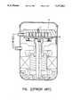
- FIG. 6is a cross-sectional view showing the whole construction of a scroll compressor equipped with the first embodiment of axial sealing apparatus according to the present invention
- FIG. 7is a perspective view showing the construction of the annular piston 21 of the scroll compressor shown in FIG. 6;
- FIG. 8is a cross-sectional view showing another type of the annular piston used in an embodiment of axial sealing apparatus according to the present invention.
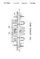
- FIG. 9is a fragmentary cross-sectional view showing the construction of another embodiment of axial sealing apparatus according to the present invention.
- a scroll compressor 20 equipped with an axial sealing apparatusprimarily comprises an orbiting scroll member 1, a stationary scroll member 2, an annular piston 21, a motor 16, a crankshaft 5, a frame 24, and a casing 29.
- the casing 29includes an upper casing member 29a, a middle casing member 29b, and a lower casing member 29c.
- the stationary scroll member 2comprises a first end plate 2ahaving a discharge port "g" formed at the center thereof, and a first scroll wrap 2b extending in a direction perpendicular to the first end plate 2a.
- a passage 2cis extended into a portion of the stationary scroll member 2.
- a suction passage 2dis formed in the peripheral wall of the stationary scroll member 2.
- the stationary scroll member 2is mounted within the middle casing member 29b, and a first enclosed space 44 is confined by the upper casing member 29a and the stationary scroll member 2.
- the first enclosed space 44is communicated with refrigeration system, which consists of a condenser 71, an expansion valve 72 and an evaporator, through a discharge pipe 46 passing through the upper casing member 29a.
- refrigeration systemwhich consists of a condenser 71, an expansion valve 72 and an evaporator
- the orbiting scroll member 1comprises a second end plate 1a and a second scroll wrap 1b extending in the direction perpendicular to the second end plate 1a.
- a coupling recess 1cis formed on the undersurface of the second end plate 1a.
- first scroll wrap and second scroll wrap 2b and 1b of the stationary scroll member 2 and the orbiting scroll member 1are meshed with each other to compress working fluid in a consecutive way and discharges compressed working fluid into the first enclosed space 44.
- the frame 24is provided with a suction passage 24a, a passage 24b, and an annular groove 24c.
- the passage 24bcommunicates with the passage 2c of the stationary scroll member 2.
- the frame 24is secured to the stationary scroll member 2.
- the annular piston 21has an inner ring 21a, an outer ring 21b, and an annular groove 21c as best shown in FIG. 7.
- the height h2 of the outer ring 21bis smaller than the height h1 of the inner ring 21a.
- FIG. 8shows another type of annular piston 27 whose shape is similar to that of the annular piston 21 except that no annular groove 21c is formed therein.
- the annular piston 21is movably fitted into the annular groove 24c defined by the inner guide ring 24e and outer guide ring 24f of the frame 24 in such a way that the annular piston 21 is capable of being slid in the annular groove 24c of the frame 24 along the longitudinal axis of the scroll compressor 20.
- a first sealing ring 37 and a second sealing ring 38are embedded respectively on the outer guide ring 24f in contact with inner guide ring 24e in contact with the inner ring 21a and outer guide ring 24f in contact with the outer ring 21b of the annular piston 21.
- sealing rings 37 and 38are able to be provided to the inner ring 21a in contact with the inner guide ring 24e and the outer ring 21b in close contact with the other guide ring 24f respectively.
- the crankshaft 5penetrates a bearing 17 mounted on the frame 24, and a boss 5a is formed at the upper end of the crankshaft 5.
- the axis of the boss 5ais eccentric to the axis of the crankshaft 5.
- the boss 5ais fitted into a bush 48 mounted in the coupling recess 1c of the orbiting scroll member 1.
- the crankshaft 5is provided with an oil passage 5b extending coaxially therewithin.
- the stator 16S of the motor 16is secured to the inner wall of the middle casing member 29b, and the crankshaft 5 is securely mounted into the rotor 16R of the motor 16.
- a second enclosed space 45 confined between the frame 24 and the stator 16sis communicated with the evaporator 73 through a suction pipe 30 extending through the wall of the middle casing member 29b.
- the lower casing member 29cis used as a reservoir of lubricant 47.
- lubricant 47is pumped upward by an oil pump (not shown) by way of the oil passage 5b to lubricate the working surface between the boss 5a and the orbiting scroll member 1, the working surface between the inner ring 21a of the annular piston 21 and the frame 24, the working surface between the crankshaft 5 and the frame 24, and the working surface between the outer ring 21b of the annular piston 21 and the frame 24.
- the orbiting scroll member 1is driven to rotate by the crank shaft 5 of the motor 16, and working fluid will be sucked into a chamber confined by the scrolls wrap 1b and 2b by way of the suction pipe 30, the suction passage 24a of the orbiting scroll member 1 and the suction passage 2d of the stationary scroll member 2.
- working fluidis consecutively compressed in the manner as described above (see FIGS. 1a, 1b and 1c). After being compressed, working fluid is discharged into the first enclosed space 44 through the discharge port "g", and then compressed working fluid is guided to enter into the condenser 71 through the discharge pipe 46. However, a portion of compressed working fluid enters the annular chamber 28 by way of the passages 2c and 24b.
- the bypassed intermediate pressure working fluidwill push the annular piston 21 to move upward and urge the orbiting scroll member 1 to exert an upward force on the stationary scroll member 2. Due to the upward force induced by the bypassed intermediate pressure working fluid, the orbiting scroll member 1 and the stationary scroll member 2 will be urged to come together, and the tip surface leakage of working fluid being compressed will thus be reduced. Furthermore, due to the existence of the sealing rings 37 and 38, lubricant coming from the lower casing member 29c will not enter the space enclosed by the stationary scroll member 2 and the orbiting scroll member 1. Thus mixing of lubricant 47 and working fluid will be reduced.
- FIG. 9shows a scroll compressor 50 equipped with a second embodiment of axial sealing apparatus according to the present invention.
- the scroll compressor 50is similar to the scroll compressor 20 shown in FIG. 5 in structure except that the passage 2c formed in stationary scroll member 2 is replaced by a passage 2e which communicates the first enclosed space 44 and the passage 24b of the frame 24.
- working fluid compressed to a high pressurewill be guided to the annular chamber 28, and produce an upward force to urge the orbiting scroll member 1 to approach the stationary scroll member 2.
- FIG. 8shows another type of the annular piston 27 capable of replacing the annular piston 21.
- the annular pistons 21 and 27are designed in such a way that the bypassed compressed working fluid is still able to enter the annular chamber 28 even though the annular piston 21 or 27 is at its lowest position where the lower end of the inner ring 21a of the annular piston 21 touches the frame 24.
- the difference between the annular piston 21 and 27is the annular piston 21 is lighter in weight than the annular piston 27 for the same material.
- the annular pistons 21 and 27are designed such that the contact position between the orbiting scroll member 1 and the annular piston 21 is located at the outer rim of the annular piston so as to obtain a longer arm.
- the wobbling of the orbiting scroll membercan be easily overcome by the annular pistons 21 and 27 of the present invention. Accordingly, tip surface leakage of the working fluid through the clearance between the tip surface of the orbiting scroll member and the first end plate surface of the stationary scroll member as well as well as between the tip surface of the stationary scroll member and the second end plate surface of the orbiting scroll member is substantially eliminated by the use of the annular piston of this invention, and the mixing of the lubricant and the compressed working fluid is greatly diminished. Therefore, the volumetric efficiency of the scroll compressor will be enhanced.
Landscapes
- Engineering & Computer Science (AREA)
- Mechanical Engineering (AREA)
- General Engineering & Computer Science (AREA)
- Rotary Pumps (AREA)
Abstract
Description
Claims (14)
Priority Applications (1)
| Application Number | Priority Date | Filing Date | Title |
|---|---|---|---|
| US07/926,522US5277563A (en) | 1992-08-10 | 1992-08-10 | Scroll compressor with axial sealing apparatus |
Applications Claiming Priority (1)
| Application Number | Priority Date | Filing Date | Title |
|---|---|---|---|
| US07/926,522US5277563A (en) | 1992-08-10 | 1992-08-10 | Scroll compressor with axial sealing apparatus |
Publications (1)
| Publication Number | Publication Date |
|---|---|
| US5277563Atrue US5277563A (en) | 1994-01-11 |
Family
ID=25453325
Family Applications (1)
| Application Number | Title | Priority Date | Filing Date |
|---|---|---|---|
| US07/926,522Expired - LifetimeUS5277563A (en) | 1992-08-10 | 1992-08-10 | Scroll compressor with axial sealing apparatus |
Country Status (1)
| Country | Link |
|---|---|
| US (1) | US5277563A (en) |
Cited By (29)
| Publication number | Priority date | Publication date | Assignee | Title |
|---|---|---|---|---|
| US5474433A (en)* | 1994-07-21 | 1995-12-12 | Industrial Technology Research Institute | Axial sealing mechanism of volute compressor |
| US5622488A (en)* | 1994-09-20 | 1997-04-22 | Hitachi, Ltd. | Scroll type fluid machine having first and second frame members to increase air tightness |
| DE19603110A1 (en)* | 1995-11-06 | 1997-05-07 | Bitzer Kuehlmaschinenbau Gmbh | compressor |
| EP0855512A1 (en)* | 1997-01-28 | 1998-07-29 | Carrier Corporation | Scroll compressor with controlled fluid venting to back pressure chamber |
| US5829959A (en)* | 1994-09-16 | 1998-11-03 | Hitachi, Ltd. | Scroll compressor |
| EP0878626A1 (en) | 1997-05-17 | 1998-11-18 | Bitzer Kühlmaschinenbau GmbH | Scroll compressor |
| DE19853240A1 (en)* | 1998-11-18 | 2000-05-31 | Bitzer Kuehlmaschinenbau Gmbh | Compressor has support body guided floating relative to housing to prevent canting and ensure elastically centred position |
| US6086335A (en)* | 1995-06-07 | 2000-07-11 | Copeland Corporation | Capacity modulated scroll machine having one or more pin members movably disposed for restricting the radius of the orbiting scroll member |
| US6129532A (en)* | 1998-02-24 | 2000-10-10 | Denso Corporation | CO2 compressor |
| US6168404B1 (en) | 1998-12-16 | 2001-01-02 | Tecumseh Products Company | Scroll compressor having axial compliance valve |
| US6461130B1 (en)* | 2000-09-08 | 2002-10-08 | Scroll Technologies | Scroll compressor with unique mounting of non-orbiting scroll |
| US20050025652A1 (en)* | 2003-07-31 | 2005-02-03 | Rechi Precision Co., Ltd. | Axial compliant means for a scroll machine |
| EP1574715A1 (en)* | 2001-02-07 | 2005-09-14 | Mitsubishi Denki Kabushiki Kaisha | Scroll compressor |
| JP2008038749A (en)* | 2006-08-07 | 2008-02-21 | Sanyo Electric Co Ltd | Closed type scroll compressor |
| CN100371600C (en)* | 2003-12-12 | 2008-02-27 | 乐金电子(天津)电器有限公司 | Vortex type compressor for preventing leakage of compressed gas |
| US20090098000A1 (en)* | 2007-10-12 | 2009-04-16 | Kirill Ignatiev | Scroll compressor with scroll deflection compensation |
| US20100196183A1 (en)* | 2009-02-03 | 2010-08-05 | Shimao Ni | Scroll compressor with materials to allow run-in |
| US20100196184A1 (en)* | 2009-02-03 | 2010-08-05 | Shimao Ni | Scroll compressor with back pressure pocket receiving discharge pressure fluid |
| US20100212352A1 (en)* | 2009-02-25 | 2010-08-26 | Cheol-Hwan Kim | Compressor and refrigerating apparatus having the same |
| US20110081269A1 (en)* | 2009-10-02 | 2011-04-07 | Industrial Technology Research Institute | Scroll compressor |
| US20150308431A1 (en)* | 2012-05-09 | 2015-10-29 | Halla Visteon Climate Control Corp. | Refrigerant scroll compressor for motor vehicle air conditioning systems |
| WO2018131235A1 (en)* | 2017-01-13 | 2018-07-19 | パナソニックIpマネジメント株式会社 | Scroll-type compressor |
| US20180223843A1 (en)* | 2017-02-06 | 2018-08-09 | Emerson Climate Technologies, Inc. | Co-rotating compressor |
| US10718330B2 (en) | 2017-02-06 | 2020-07-21 | Emerson Climate Technologies, Inc. | Co-rotating compressor with multiple compression mechanisms |
| US10995754B2 (en) | 2017-02-06 | 2021-05-04 | Emerson Climate Technologies, Inc. | Co-rotating compressor |
| US11359631B2 (en) | 2019-11-15 | 2022-06-14 | Emerson Climate Technologies, Inc. | Co-rotating scroll compressor with bearing able to roll along surface |
| US11624366B1 (en) | 2021-11-05 | 2023-04-11 | Emerson Climate Technologies, Inc. | Co-rotating scroll compressor having first and second Oldham couplings |
| US11732713B2 (en) | 2021-11-05 | 2023-08-22 | Emerson Climate Technologies, Inc. | Co-rotating scroll compressor having synchronization mechanism |
| US12104594B2 (en) | 2021-11-05 | 2024-10-01 | Copeland Lp | Co-rotating compressor |
Citations (2)
| Publication number | Priority date | Publication date | Assignee | Title |
|---|---|---|---|---|
| JPH02191888A (en)* | 1989-01-20 | 1990-07-27 | Matsushita Refrig Co Ltd | Scroll type fluid machine |
| JPH0378586A (en)* | 1989-08-21 | 1991-04-03 | Daikin Ind Ltd | scroll type fluid device |
- 1992
- 1992-08-10USUS07/926,522patent/US5277563A/ennot_activeExpired - Lifetime
Patent Citations (2)
| Publication number | Priority date | Publication date | Assignee | Title |
|---|---|---|---|---|
| JPH02191888A (en)* | 1989-01-20 | 1990-07-27 | Matsushita Refrig Co Ltd | Scroll type fluid machine |
| JPH0378586A (en)* | 1989-08-21 | 1991-04-03 | Daikin Ind Ltd | scroll type fluid device |
Cited By (49)
| Publication number | Priority date | Publication date | Assignee | Title |
|---|---|---|---|---|
| US5474433A (en)* | 1994-07-21 | 1995-12-12 | Industrial Technology Research Institute | Axial sealing mechanism of volute compressor |
| US6174150B1 (en) | 1994-09-16 | 2001-01-16 | Hitachi, Ltd. | Scroll compressor |
| US5829959A (en)* | 1994-09-16 | 1998-11-03 | Hitachi, Ltd. | Scroll compressor |
| US5622488A (en)* | 1994-09-20 | 1997-04-22 | Hitachi, Ltd. | Scroll type fluid machine having first and second frame members to increase air tightness |
| CN1070266C (en)* | 1994-09-20 | 2001-08-29 | 株式会社日立制作所 | Scroll type fluid machine |
| USRE40554E1 (en)* | 1995-06-07 | 2008-10-28 | Emerson Climate Technologies, Inc. | Capacity modulated scroll machine having one or more pin members movably disposed for restricting the radius of the orbiting scroll member |
| USRE40400E1 (en) | 1995-06-07 | 2008-06-24 | Emerson Climate Technologies, Inc. | Capacity modulated scroll machine |
| US6086335A (en)* | 1995-06-07 | 2000-07-11 | Copeland Corporation | Capacity modulated scroll machine having one or more pin members movably disposed for restricting the radius of the orbiting scroll member |
| DE19603110A1 (en)* | 1995-11-06 | 1997-05-07 | Bitzer Kuehlmaschinenbau Gmbh | compressor |
| EP0855512A1 (en)* | 1997-01-28 | 1998-07-29 | Carrier Corporation | Scroll compressor with controlled fluid venting to back pressure chamber |
| DE19720790A1 (en)* | 1997-05-17 | 1998-12-03 | Bitzer Kuehlmaschinenbau Gmbh | compressor |
| EP0878626A1 (en) | 1997-05-17 | 1998-11-18 | Bitzer Kühlmaschinenbau GmbH | Scroll compressor |
| US6129532A (en)* | 1998-02-24 | 2000-10-10 | Denso Corporation | CO2 compressor |
| DE19853240A1 (en)* | 1998-11-18 | 2000-05-31 | Bitzer Kuehlmaschinenbau Gmbh | Compressor has support body guided floating relative to housing to prevent canting and ensure elastically centred position |
| US6168404B1 (en) | 1998-12-16 | 2001-01-02 | Tecumseh Products Company | Scroll compressor having axial compliance valve |
| US6461130B1 (en)* | 2000-09-08 | 2002-10-08 | Scroll Technologies | Scroll compressor with unique mounting of non-orbiting scroll |
| US6461132B1 (en) | 2000-09-08 | 2002-10-08 | Scroll Technologies | Scroll compressor with unique mounting of non-orbiting scroll |
| US6547543B2 (en) | 2000-09-08 | 2003-04-15 | Scroll Technologies | Scroll compressor with unique mounting of non-orbiting scroll |
| EP1574715A1 (en)* | 2001-02-07 | 2005-09-14 | Mitsubishi Denki Kabushiki Kaisha | Scroll compressor |
| US6896497B2 (en)* | 2003-07-31 | 2005-05-24 | Rechi Precision Co., Ltd. | Axial compliant means for a scroll machine |
| US20050025652A1 (en)* | 2003-07-31 | 2005-02-03 | Rechi Precision Co., Ltd. | Axial compliant means for a scroll machine |
| CN100371600C (en)* | 2003-12-12 | 2008-02-27 | 乐金电子(天津)电器有限公司 | Vortex type compressor for preventing leakage of compressed gas |
| JP2008038749A (en)* | 2006-08-07 | 2008-02-21 | Sanyo Electric Co Ltd | Closed type scroll compressor |
| US7997883B2 (en) | 2007-10-12 | 2011-08-16 | Emerson Climate Technologies, Inc. | Scroll compressor with scroll deflection compensation |
| US20090098000A1 (en)* | 2007-10-12 | 2009-04-16 | Kirill Ignatiev | Scroll compressor with scroll deflection compensation |
| US20100196183A1 (en)* | 2009-02-03 | 2010-08-05 | Shimao Ni | Scroll compressor with materials to allow run-in |
| WO2010090854A1 (en)* | 2009-02-03 | 2010-08-12 | Scrolllabs Corporation | Scroll compressor with back pressure pocket receiving discharge pressure fluid |
| US20100196184A1 (en)* | 2009-02-03 | 2010-08-05 | Shimao Ni | Scroll compressor with back pressure pocket receiving discharge pressure fluid |
| CN102301094A (en)* | 2009-02-03 | 2011-12-28 | 涡旋实验室公司 | Scroll compressor with back pressure pocket receiving discharge pressure fluid |
| US8157551B2 (en) | 2009-02-03 | 2012-04-17 | Scrollabs Corporation | Scroll compressor with back pressure pocket receiving discharge pressure fluid |
| US8167594B2 (en) | 2009-02-03 | 2012-05-01 | Scrolllabs Corporation | Scroll compressor with materials to allow run-in |
| CN102301094B (en)* | 2009-02-03 | 2013-11-27 | 涡旋实验室公司 | Scroll compressor with back pressure pocket receiving discharge pressure fluid |
| US20100212352A1 (en)* | 2009-02-25 | 2010-08-26 | Cheol-Hwan Kim | Compressor and refrigerating apparatus having the same |
| EP2243958A3 (en)* | 2009-02-25 | 2011-01-19 | LG Electronics, Inc. | Compressor and refrigerating apparatus having the same |
| US20110081269A1 (en)* | 2009-10-02 | 2011-04-07 | Industrial Technology Research Institute | Scroll compressor |
| US9945380B2 (en)* | 2012-05-09 | 2018-04-17 | Hanon Systems | Refrigerant scroll compressor for motor vehicle air conditioning system including at least one sealing means for bottom surface sealing of orbiting scroll |
| US20150308431A1 (en)* | 2012-05-09 | 2015-10-29 | Halla Visteon Climate Control Corp. | Refrigerant scroll compressor for motor vehicle air conditioning systems |
| JPWO2018131235A1 (en)* | 2017-01-13 | 2019-11-07 | パナソニックIpマネジメント株式会社 | Scroll compressor |
| WO2018131235A1 (en)* | 2017-01-13 | 2018-07-19 | パナソニックIpマネジメント株式会社 | Scroll-type compressor |
| US11111921B2 (en)* | 2017-02-06 | 2021-09-07 | Emerson Climate Technologies, Inc. | Co-rotating compressor |
| US10718330B2 (en) | 2017-02-06 | 2020-07-21 | Emerson Climate Technologies, Inc. | Co-rotating compressor with multiple compression mechanisms |
| US10995754B2 (en) | 2017-02-06 | 2021-05-04 | Emerson Climate Technologies, Inc. | Co-rotating compressor |
| US20180223843A1 (en)* | 2017-02-06 | 2018-08-09 | Emerson Climate Technologies, Inc. | Co-rotating compressor |
| US11359631B2 (en) | 2019-11-15 | 2022-06-14 | Emerson Climate Technologies, Inc. | Co-rotating scroll compressor with bearing able to roll along surface |
| US11624366B1 (en) | 2021-11-05 | 2023-04-11 | Emerson Climate Technologies, Inc. | Co-rotating scroll compressor having first and second Oldham couplings |
| US11732713B2 (en) | 2021-11-05 | 2023-08-22 | Emerson Climate Technologies, Inc. | Co-rotating scroll compressor having synchronization mechanism |
| US11994128B2 (en) | 2021-11-05 | 2024-05-28 | Copeland Lp | Co-rotating scroll compressor with Oldham couplings |
| US12104594B2 (en) | 2021-11-05 | 2024-10-01 | Copeland Lp | Co-rotating compressor |
| US12345258B2 (en) | 2021-11-05 | 2025-07-01 | Copeland Lp | Co-rotating scroll compressor having synchronization mechanism |
Similar Documents
| Publication | Publication Date | Title |
|---|---|---|
| US5277563A (en) | Scroll compressor with axial sealing apparatus | |
| US7229261B2 (en) | Scroll compressor having an annular recess located outside an annular seal portion and another recess communicating with suction port of fixed scroll | |
| CA1329183C (en) | Delivery pressure operated thrust control system for working contact surfaces in a scroll compressor | |
| AU655977B2 (en) | Orbiting rotary compressor | |
| EP0443705B1 (en) | Scroll compressor | |
| KR100916554B1 (en) | Scroll compressor having a clearance for the oldham coupling | |
| KR101300261B1 (en) | Scroll compressor | |
| US6071100A (en) | Scroll compressor having lubrication of the rotation preventing member | |
| US7967584B2 (en) | Scroll machine using floating seal with backer | |
| KR19980070415A (en) | compressor | |
| EP1818541B1 (en) | Horizontally-mounted scroll compressor | |
| JP3658831B2 (en) | Scroll compressor | |
| JP2631839B2 (en) | Scroll compressor | |
| EP0683321B1 (en) | Swinging rotary compressor | |
| US5622488A (en) | Scroll type fluid machine having first and second frame members to increase air tightness | |
| US5577903A (en) | Rotary compressor | |
| JPH07189924A (en) | Rotary compressor | |
| JP2008121481A (en) | Scroll fluid machinery | |
| JPH04143483A (en) | rolling piston compressor | |
| KR102232272B1 (en) | Motor operated compressor | |
| US5573389A (en) | Scroll compressor having means for biasing an eccentric bearing towards a crank shaft | |
| JPH06264881A (en) | Rotary compressor | |
| KR101300258B1 (en) | Scroll compressor | |
| JPH08319959A (en) | Scroll compressor | |
| KR20010076889A (en) | Low pressure type rotary compressor |
Legal Events
| Date | Code | Title | Description |
|---|---|---|---|
| AS | Assignment | Owner name:INDUSTRIAL TECHNOLOGY RESEARCH INSTITUTE, TAIWAN Free format text:ASSIGNMENT OF ASSIGNORS INTEREST.;ASSIGNORS:WEN-JEN, KUO;WEN-DING, TSENG;CHIH-CHENG, YANG;AND OTHERS;REEL/FRAME:006176/0462 Effective date:19920706 | |
| STCF | Information on status: patent grant | Free format text:PATENTED CASE | |
| FEPP | Fee payment procedure | Free format text:PAT HLDR NO LONGER CLAIMS SMALL ENT STAT AS NONPROFIT ORG (ORIGINAL EVENT CODE: LSM3); ENTITY STATUS OF PATENT OWNER: LARGE ENTITY Free format text:PAYOR NUMBER ASSIGNED (ORIGINAL EVENT CODE: ASPN); ENTITY STATUS OF PATENT OWNER: LARGE ENTITY | |
| FPAY | Fee payment | Year of fee payment:4 | |
| FEPP | Fee payment procedure | Free format text:PAYOR NUMBER ASSIGNED (ORIGINAL EVENT CODE: ASPN); ENTITY STATUS OF PATENT OWNER: LARGE ENTITY Free format text:PAYER NUMBER DE-ASSIGNED (ORIGINAL EVENT CODE: RMPN); ENTITY STATUS OF PATENT OWNER: LARGE ENTITY | |
| FEPP | Fee payment procedure | Free format text:PAYOR NUMBER ASSIGNED (ORIGINAL EVENT CODE: ASPN); ENTITY STATUS OF PATENT OWNER: LARGE ENTITY Free format text:PAYER NUMBER DE-ASSIGNED (ORIGINAL EVENT CODE: RMPN); ENTITY STATUS OF PATENT OWNER: LARGE ENTITY | |
| FPAY | Fee payment | Year of fee payment:8 | |
| FPAY | Fee payment | Year of fee payment:12 |