US5277392A - Adjustable computer monitor arm and method - Google Patents
Adjustable computer monitor arm and methodDownload PDFInfo
- Publication number
- US5277392A US5277392AUS07/963,118US96311892AUS5277392AUS 5277392 AUS5277392 AUS 5277392AUS 96311892 AUS96311892 AUS 96311892AUS 5277392 AUS5277392 AUS 5277392A
- Authority
- US
- United States
- Prior art keywords
- monitor
- shaft
- support platform
- arm
- monitor support
- Prior art date
- Legal status (The legal status is an assumption and is not a legal conclusion. Google has not performed a legal analysis and makes no representation as to the accuracy of the status listed.)
- Expired - Fee Related
Links
Images


Classifications
- F—MECHANICAL ENGINEERING; LIGHTING; HEATING; WEAPONS; BLASTING
- F16—ENGINEERING ELEMENTS AND UNITS; GENERAL MEASURES FOR PRODUCING AND MAINTAINING EFFECTIVE FUNCTIONING OF MACHINES OR INSTALLATIONS; THERMAL INSULATION IN GENERAL
- F16M—FRAMES, CASINGS OR BEDS OF ENGINES, MACHINES OR APPARATUS, NOT SPECIFIC TO ENGINES, MACHINES OR APPARATUS PROVIDED FOR ELSEWHERE; STANDS; SUPPORTS
- F16M13/00—Other supports for positioning apparatus or articles; Means for steadying hand-held apparatus or articles
- F16M13/02—Other supports for positioning apparatus or articles; Means for steadying hand-held apparatus or articles for supporting on, or attaching to, an object, e.g. tree, gate, window-frame, cycle
- F16M13/022—Other supports for positioning apparatus or articles; Means for steadying hand-held apparatus or articles for supporting on, or attaching to, an object, e.g. tree, gate, window-frame, cycle repositionable
- F—MECHANICAL ENGINEERING; LIGHTING; HEATING; WEAPONS; BLASTING
- F16—ENGINEERING ELEMENTS AND UNITS; GENERAL MEASURES FOR PRODUCING AND MAINTAINING EFFECTIVE FUNCTIONING OF MACHINES OR INSTALLATIONS; THERMAL INSULATION IN GENERAL
- F16M—FRAMES, CASINGS OR BEDS OF ENGINES, MACHINES OR APPARATUS, NOT SPECIFIC TO ENGINES, MACHINES OR APPARATUS PROVIDED FOR ELSEWHERE; STANDS; SUPPORTS
- F16M11/00—Stands or trestles as supports for apparatus or articles placed thereon ; Stands for scientific apparatus such as gravitational force meters
- F16M11/02—Heads
- F16M11/04—Means for attachment of apparatus; Means allowing adjustment of the apparatus relatively to the stand
- F16M11/06—Means for attachment of apparatus; Means allowing adjustment of the apparatus relatively to the stand allowing pivoting
- F16M11/12—Means for attachment of apparatus; Means allowing adjustment of the apparatus relatively to the stand allowing pivoting in more than one direction
- F16M11/126—Means for attachment of apparatus; Means allowing adjustment of the apparatus relatively to the stand allowing pivoting in more than one direction for tilting and panning
- F—MECHANICAL ENGINEERING; LIGHTING; HEATING; WEAPONS; BLASTING
- F16—ENGINEERING ELEMENTS AND UNITS; GENERAL MEASURES FOR PRODUCING AND MAINTAINING EFFECTIVE FUNCTIONING OF MACHINES OR INSTALLATIONS; THERMAL INSULATION IN GENERAL
- F16M—FRAMES, CASINGS OR BEDS OF ENGINES, MACHINES OR APPARATUS, NOT SPECIFIC TO ENGINES, MACHINES OR APPARATUS PROVIDED FOR ELSEWHERE; STANDS; SUPPORTS
- F16M11/00—Stands or trestles as supports for apparatus or articles placed thereon ; Stands for scientific apparatus such as gravitational force meters
- F16M11/20—Undercarriages with or without wheels
- F16M11/24—Undercarriages with or without wheels changeable in height or length of legs, also for transport only, e.g. by means of tubes screwed into each other
- F—MECHANICAL ENGINEERING; LIGHTING; HEATING; WEAPONS; BLASTING
- F16—ENGINEERING ELEMENTS AND UNITS; GENERAL MEASURES FOR PRODUCING AND MAINTAINING EFFECTIVE FUNCTIONING OF MACHINES OR INSTALLATIONS; THERMAL INSULATION IN GENERAL
- F16M—FRAMES, CASINGS OR BEDS OF ENGINES, MACHINES OR APPARATUS, NOT SPECIFIC TO ENGINES, MACHINES OR APPARATUS PROVIDED FOR ELSEWHERE; STANDS; SUPPORTS
- F16M2200/00—Details of stands or supports
- F16M2200/02—Locking means
- F16M2200/021—Locking means for rotational movement
- F16M2200/022—Locking means for rotational movement by friction
- Y—GENERAL TAGGING OF NEW TECHNOLOGICAL DEVELOPMENTS; GENERAL TAGGING OF CROSS-SECTIONAL TECHNOLOGIES SPANNING OVER SEVERAL SECTIONS OF THE IPC; TECHNICAL SUBJECTS COVERED BY FORMER USPC CROSS-REFERENCE ART COLLECTIONS [XRACs] AND DIGESTS
- Y10—TECHNICAL SUBJECTS COVERED BY FORMER USPC
- Y10S—TECHNICAL SUBJECTS COVERED BY FORMER USPC CROSS-REFERENCE ART COLLECTIONS [XRACs] AND DIGESTS
- Y10S248/00—Supports
- Y10S248/917—Video display screen support
- Y10S248/919—Adjustably orientable video screen support
- Y10S248/92—Angular and linear video display screen support adjustment
Definitions
- monitor supportswhich are designed to be secured to a table or desk top and to support a computer or other video screen monitor in a proper viewing position by a user
- monitor support apparatusalso have a keyboard support, associated with the monitor support, to provide support for a keyboard used with the monitor generally in front of and beneath the supported monitor screen.
- monitor and optionally a monitor and keyboard support apparatuswhich may be adjusted; particularly, easily adjusted by the user to provide for the correct vertical height of the monitor and keyboard for the user.
- the inventionrelates to an adjustable monitor support apparatus and method of supporting and adjusting a monitor to a desired viewing position.
- the monitor support apparatusprovides the user an easy and effective means to adjust the vertical height of the monitor support platform.
- the inventionconcerns an adjustable monitor, and optionally a keyboard support apparatus, for the adjustable positioning of a monitor having a monitor screen, and optionally a keyboard, which apparatus comprises a generally vertical base means having a one and another end which comprises a generally vertical shaft bushing about the base shaft, and an outer sleeve about the shaft and shaft bushing; and, for example, a generally horizontal, elongated angular monitor arm of diecast aluminum having a one end and another end, the one end of the monitor arm secured to the shaft bushing for rotation of the monitor arm about the shaft.
- the apparatusincludes a monitor support platform adapted to support a monitor on the generally horizontal top surface of the monitor support platform, the other end of the monitor arm secured to the bottom surface of the monitor support platform; and a means, such as an upright shaft, centrally located, to provide for the axial rotation of the monitor support platform at the other end of the monitor arm in a generally horizontal plane; and means, such as an adjustable handle, on a shaft below the platform to secure the monitor support platform in a selected locked position in a generally horizontal plane after rotation to the selected position; means, such as a clamp assembly, to secure the one end of the base means to a surface, above which surface a monitor is to be positioned.
- the apparatusalso includes spacer means, typically a plurality of spacers, such as selected incremental, removable, arrangeable, individual spacers within the sleeve, to permit the vertical adjustment of the height of the one end of the monitor arm on the shaft bushing by the user selection of the arrangement of the spacers within the sleeve, so as to provide for the desired corresponding height of the monitor support platform at the other end of the monitor arm.
- spacer meanstypically a plurality of spacers, such as selected incremental, removable, arrangeable, individual spacers within the sleeve, to permit the vertical adjustment of the height of the one end of the monitor arm on the shaft bushing by the user selection of the arrangement of the spacers within the sleeve, so as to provide for the desired corresponding height of the monitor support platform at the other end of the monitor arm.
- the apparatusmay optionally include means to tilt slidably the monitor support platform to adjust the angular position of the monitor on the monitor support platform, such as by an elongated slot generally centrally disposed in the monitor support platform, a threaded shaft extending through the said slot, and a lock nut threadably connected to the said shaft, the monitor support platform slidable along the slot and fixed in position by the lock nut.
- the apparatusmay also optionally include a keyboard support means to support a keyboard in front of the monitor, which keyboard support is slidably mounted between the monitor support platform and moves between a stored non-use position and a generally horizontal outwardly-extending use position from the monitor support arm.
- a keyboard support meansto support a keyboard in front of the monitor, which keyboard support is slidably mounted between the monitor support platform and moves between a stored non-use position and a generally horizontal outwardly-extending use position from the monitor support arm.
- a keyboard support meansto support a keyboard in front of the monitor, which keyboard support is slidably mounted between the monitor support platform and moves between a stored non-use position and a generally horizontal outwardly-extending use position from the monitor support arm.
- a generally U-shaped wireslidably mounted beneath the monitor support platform and having a short, upwardly extending front to retain the keyboard in position and stop means to prevent the entire slidable withdrawal of the wire in use.
- the methodprovides for the proper, rapid and easy positioning of a monitor on a monitor support apparatus which comprises a generally vertical base, a monitor support arm having a one and other end generally horizontally extending at the one end from the base, and a monitor support platform at the other end of the base, and a monitor on the monitor support platform.
- the methodcomprises securing the monitor support apparatus to a surface; rotating the monitor arm to a desired monitor viewing position; rotating and securing the monitor support platform to a desired monitor viewing position; and vertically adjusting by selected space increments the height of the one end of the monitor arm about the shaft to adjust the vertical height of the monitor support platform and monitor.
- the monitor support apparatus of the inventionincludes means to provide for the simple and easy adjustment by the user of the vertical height of the support platform at the other end of the monitor arm, so that a correct viewing position of the monitor is easily obtained.
- the vertical height of the one end of the monitor arm extending outwardly from the base meansis adjusted by the arrangement in the base means of individual separate spacer elements.
- the spacer elementsmay be of the same or varied height, but generally are of uniform height, so that each movement of spacer elements represents a uniform change in vertical height; for example, spacer elements may be in 1/4, 1/2, 3/4 or 1 or more inch increments, or combinations thereof.
- the spacer elements in one preferred embodimentare designed to be stacked together vertically in an interlocking, mating relationship from a base, which base contains a static raised ridge to interlock with the elongated opening on the bottom of the first spacer element.
- Each of the spacer elementshave a receiving slot or opening on the one, for example, bottom surface and a raised ridge on the other, for example, the top surface matingly receivable in the slot or opening of the next stacked spacer element, so that the selected stacked spacer elements are interlocked together to provide the proper support beneath the shaft bushing and interlocked together above the shaft bushing for storage and design purposes.
- the monitor armis composed of a lightweight metal material, such as diecast metal like aluminum or an aluminum alloy, and generally the spacer elements are of the same or similar material.
- the spacer elementscomprise a plurality of spacer elements in a vertically stacked arrangement either above or below or both above and below the shaft bushing from which extends the monitor arm, so that the position of the rotatable shaft bushing and the one end of the monitor arm on the vertical shaft of the base means may be adjusted.
- the spacer elementshave a one arcuate surface end, which is a concave surface which closely fits and mimics the shaft diameter, and an outer other surface to be grasped or handled by the user, generally with a friction-type, corrugated or roughened surface.
- the spacer elementsare positioned within a vertical slot in the outer sleeve about the shaft and shaft bushing and from which slot the monitor arm extends outwardly.
- the sleevehas a top cap f or enclosing the top of the shaft and sleeve and to secure the interlocked spacer elements on the base of the monitor arm.
- the number of spacer elementsmay vary as desired, but generally would use from about 6 to 12 spacer elements, said elements 1/2 of an inch in height, which permits a height adjustment of 3 to 6 inches.
- the spacer elements contained above the shaft bushingdo not provide height adjustment, but represent an inventory for other adjustments and fill the slot for design purposes.
- the monitor armextends generally horizontally outward, but typically at an upward angle of, for example, 5 to 30 degrees, such as 10 to 15 degrees, and has a length which may vary, but generally is from about 18 to 30 inches in length.
- the monitor armhas a monitor support platform at the other end, typically of a hard, plastic material and which includes means to rotate or pivot the platform in a horizontal plane about a central shaft.
- the platformhas a centrally positioned, contoured, depressed, circular area with an elongated arcuate straight slot therein so that the rotatable platform also may be slightly tilted from the horizontal plane, e.g., about 2 to 15 degrees, so as to tilt the supported monitor from the horizontal plane to a better viewing position.
- a shaftextends through the elongated slot and has an adjustable knob at the lower end below the platform, so that after rotation and tilting the platform can be locked in a position by tightening the knob, while the upper end of the shaft includes a captive nut or screw extending greater than the slot width and a lock nut at the end of this shaft, so that the adjusting knob on the threaded lower end of the shaft may be threadably tightened to place the platform in a locked position.
- the monitor support apparatusincludes means to secure the apparatus to a surface, such as a desk top; such as, but not limited to, bolts, screws, or by a threaded removable adjustable clamp assembly on a mounting bracket from which the base means extends.
- the monitor support apparatusincludes a keyboard support to support a keyboard in front of the supported monitor, such as a wire frame, slidably mounted for movement by the user between a non-use stored position beneath the platform and an outward-extending use position in front of the platform.
- a keyboard supportto support a keyboard in front of the supported monitor, such as a wire frame, slidably mounted for movement by the user between a non-use stored position beneath the platform and an outward-extending use position in front of the platform.
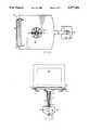
- FIG. 1is a perspective view from above of the monitor support apparatus of the invention.
- FIG. 2is a side plan view with a portion in section of the apparatus of FIG. 1.
- FIG. 3is a top plan view of the apparatus of FIG. 1.
- FIG. 4is a front plan view of the apparatus of FIG. 1 with a supported monitor shown in dotted lines.
- FIG. 5is a perspective view of a spacer element of the apparatus of FIG. 2.
- FIG. 6is a side plan view of a plurality of spacer elements of FIG. 5 in a stacked position.
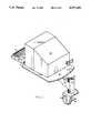
- FIG. 7is a perspective view from above of the apparatus of FIG. 1 with a supported monitor and supported keyboard.
- an adjustable monitor support apparatus 10with a computer monitor 58 with a video screen supported in a viewing position and with a keyboard 60 supported by a keyboard support 36 in an extended use position beneath the monitor 58 (see FIG. 7).
- the apparatus 10includes a generally vertical fixed shaft 12, with a shaft bushing 14 and a horizontally extended, upwardly-angled, diecast aluminum monitor arm 16 secured to the shaft bushing 14 at the one end for axial rotation of the monitor arm about the shaft 12.
- the apparatus 10includes an outer sleeve 18 about the shaft 12 and shaft bushing 14 with an elongated slot 28 in the vertically extended sleeve 18, through which slot 28 extends monitor arm 16.
- a solid cap 20is fitted on top of the sleeve 18 and covers the shaft and shaft bushing and a plurality of vertically stacked spacer elements 22.
- spacer elements 22are vertically stacked within the sleeve 18 and extend outwardly from the slot 28. As illustrated, three spacer elements 22 are stacked beneath and support the shaft bushing 14 with three spacer elements 22 stored above the shaft bushing 14 and beneath cap 20. Each of the spacer elements 22 have an arcuate concave surface 24 at the one end which mimics the diameter of the shaft 12 and fits adjacent the shaft 12 surface, while the other end of the spacer elements 22 have a plurality of generally vertical corrugations 26 for ease in the removing, replacing and arranging the spacer elements 22 in position adjacent to the shaft 12 and within sleeve 18.
- the spacer elements 22are selected by the user to provide the desired vertical height of the one end of the monitor arm 16 on the shaft 12 which then adjusts the height of the other end of the monitor arm 16, which contains a monitor support platform 30, and adjusts the vertical height of the supported monitor 58 and the supported keyboard 60.
- the upper section of the monitor arm 16includes an elongated slot or opening 74 to receive in an interlocked mating arrangement the raised ridge 76 of the adjacent lower spacer element 22 to lock the shaft bushing 14 into place with the vertical stacked supporting spacer elements 22.
- the top section of the monitor arm 16includes an elongated slot or opening 78 which is adapted to fit in an interlocked mating arrangement with a raised edge 80 on the bottom of the first spacer element 22 on top of the shaft bushing 14.
- the shaft bushing 14is interlocked above and below with the interlocked vertical stack of spacer elements 22 on the base and is surrounded by the sleeve 18 and has a top cap 20 to provide a secure, interlocked, supported, rotatable shaft locking within the sleeve 18.
- the position of the raised ridges and elongated openingsmay be reversed to provide the same or similar interlocked structure, starting from the base 34 upwardly.
- the spacer elementscontain a raised elongated ridge 74 on the bottom surface which matingly fits within and engages an elongated slot 76 on the top surface of the next higher spacer element (see FIGS. 5 and 6).
- the interlocked, vertically stacked spacer elementsare selected by the user to provide the desired height of the monitor arm 16 and to support the shaft bushing 14 to which the monitor arm 16 is secured for rotation thereabout.
- the shaft 12is secured to and extends upward from a right-angled metal bracket 38 having holes 40 on one side, to permit the bracket to be screwed or bolted to a surface.
- a clamp assemblyis secured to the bracket 38 by clamp mount 44 with a threaded shaft 42 therethrough with a clamp cap 46 at the one end of the shaft 42 and a handle 48 for threadably turning the shaft 42 to force the clamp cap 46 into a clamping position such as on to a desk top 50.
- the monitor support platform 30has a peripheral lip and a short upward front tray extension 62 to aid in retaining the monitor on the platform 30 and the platform 30 is rotatably secured to the other end of the monitor arm 16 by a vertical threaded shaft 66, having a knurled adjusting knob 72 at the lower end beneath the support platform 30, and which shaft 66 extends through an elongated opening 32 in a circular depressed area 64 of the platform 30 to a captive nut 70 which extends beyond opening 32 and an angular locking nut 68.
- the platformincludes a generally centrally positioned circular depression 64 about the elongated slot 32.
- the support platformis formed of an injection-molded plastic material.
- the knurled adjustable knobprovides for the easy release or locking of the platform 30 which is free to rotate about shaft 66 in a generally horizontal plane, and also to be tilted slidably along the slot 32 to a desired tilted viewing position, and then by turning or tightening the knob 72 the platform 30 is locked in the supported tilted view position by the user.
- the support platform 30includes a keyboard support 36 which comprises a U-shaped wire support having a short upward front extension 54 to help retain the supported keyboard 60 in position.
- the wire frame keyboard support 36is slidably mounted within a pair of spaced-apart friction-type supports 56 secured to the bottom surface of the support platform 30 to provide for the slidable movement by the user of the keyboard support 36 between a stored non-use position (see FIGS. 1-4) and a front, outwardly extending use position (Fig. 7).
- the apparatus 10is secured to desk top 50 by clamp assembly (42, 44, 46 and 48).
- the vertical height of the monitor arm 16is selected by the user arranging and positioning the spacer elements 22 in a vertically stacked manner within sleeve 18 with a greater height achieved if all of the spacer elements 22 are inserted under the shaft bushing 14.
- the arrangement of the spacer element 22is accomplished by removing cap 20 and then inserting and rearranging the spacer elements 22.
- the monitor arm 16then may be rotated to a desired monitor viewing position, and the monitor support platform 30 rotated and tilted to a desired position and then locked in place by locking knob 72.
- the weight of the monitor 58 at the end of the monitor arm 16 on platform 30is sufficient to retain the monitor arm 16 in the selected position.
- the keyboard support arm frame 36may then be slidably extended to the use position and a keyboard 60 placed thereon.
- the invention as described and illustratedprovides for a simple, easily adjustable monitor support apparatus and method.
Landscapes
- Engineering & Computer Science (AREA)
- General Engineering & Computer Science (AREA)
- Mechanical Engineering (AREA)
- Devices For Indicating Variable Information By Combining Individual Elements (AREA)
Abstract
Description
Claims (25)
Priority Applications (1)
| Application Number | Priority Date | Filing Date | Title |
|---|---|---|---|
| US07/963,118US5277392A (en) | 1992-10-19 | 1992-10-19 | Adjustable computer monitor arm and method |
Applications Claiming Priority (1)
| Application Number | Priority Date | Filing Date | Title |
|---|---|---|---|
| US07/963,118US5277392A (en) | 1992-10-19 | 1992-10-19 | Adjustable computer monitor arm and method |
Publications (1)
| Publication Number | Publication Date |
|---|---|
| US5277392Atrue US5277392A (en) | 1994-01-11 |
Family
ID=25506774
Family Applications (1)
| Application Number | Title | Priority Date | Filing Date |
|---|---|---|---|
| US07/963,118Expired - Fee RelatedUS5277392A (en) | 1992-10-19 | 1992-10-19 | Adjustable computer monitor arm and method |
Country Status (1)
| Country | Link |
|---|---|
| US (1) | US5277392A (en) |
Cited By (64)
| Publication number | Priority date | Publication date | Assignee | Title |
|---|---|---|---|---|
| USD363065S (en) | 1994-10-17 | 1995-10-10 | Rubbermaid Office Products Inc. | Monitor arm |
| US5553820A (en)* | 1994-10-17 | 1996-09-10 | Rubbermaid Office Products Inc. | Adjustable monitor arm |
| US5590607A (en)* | 1994-09-01 | 1997-01-07 | Howard; Thomas E. | Portable shelf for notebook computers |
| USD379144S (en)* | 1995-11-16 | 1997-05-13 | Hunter Delphine G | Wall mount for television receiver |
| USD379426S (en)* | 1995-12-20 | 1997-05-27 | Vogel's Holding B.V. | Support for a television and audio/video equipment |
| USD383376S (en)* | 1995-06-23 | 1997-09-09 | Vogel's Holding B.V. | Support for a television and audio/video equipment |
| US5667179A (en)* | 1994-09-30 | 1997-09-16 | Rosen; John B. | Ratcheting articulable monitor support and presentation device |
| US5709360A (en)* | 1994-09-30 | 1998-01-20 | Rosen; John B. | Ratcheting articulable monitor support and presentation device |
| US5722622A (en)* | 1996-06-24 | 1998-03-03 | Gustafson; Norman P. | Stable-slide self-feeding assistive device |
| GB2322538A (en)* | 1997-02-28 | 1998-09-02 | Haropa Prod Ltd | Wall-mounted support arm |
| FR2770725A1 (en)* | 1997-11-03 | 1999-05-07 | Source Dev | Flat panel display monitor and supporting stand |
| US5918845A (en)* | 1995-02-24 | 1999-07-06 | Commercial Brains Limited | Support brackets |
| US5938159A (en)* | 1997-07-10 | 1999-08-17 | Hung; Teng-Shun | Computer monitor supporting bracket |
| US5992810A (en)* | 1997-08-29 | 1999-11-30 | Ergotech (1993) Inc. | Adjustable keyboard support |
| US6047939A (en)* | 1997-07-09 | 2000-04-11 | Lg Electronics Inc. | Adjustable support structure for video appliance |
| USD433405S (en)* | 1999-12-14 | 2000-11-07 | Vieira Richard S | Speaker mounting apparatus |
| USD433926S (en)* | 1999-03-13 | 2000-11-21 | Avf Group Limited | Bracket, principally for supporting a television set |
| US6164611A (en)* | 1997-09-18 | 2000-12-26 | Gamber Johnson | Quad-motion device |
| USD436097S1 (en) | 1998-02-04 | 2001-01-09 | Lior Barkan | Tray for a television support |
| US6208505B1 (en)* | 1998-09-09 | 2001-03-27 | Gerber Technology, Inc. | Computer, keyboard, and flat screen monitor support assembly |
| US6450466B1 (en)* | 2000-08-02 | 2002-09-17 | Wooster Toy Kraft Llc | Suspension bracket for fireplace mantel |
| WO2002102190A2 (en) | 2001-06-19 | 2002-12-27 | Innovative Office Products, Inc. | Configurable mount for a peripheral device |
| US20030060270A1 (en)* | 2001-09-27 | 2003-03-27 | Binkley Wesley A. | Articulating gaming terminals, systems including such terminals, and methods |
| US20030156094A1 (en)* | 2002-02-20 | 2003-08-21 | Chen Yeong Kuen | Angular adjustment device for a plane display |
| US6619603B1 (en)* | 1999-06-11 | 2003-09-16 | Brunswick Bowling & Billiards Corporation | Table-mounted bowling scoring unit |
| US20050040299A1 (en)* | 2003-08-22 | 2005-02-24 | Twyford Robert H. | Apparatus and method for universal mounting of a computer system in a vehicle |
| US20050133678A1 (en)* | 2002-06-11 | 2005-06-23 | Chief Manufacturing Inc. | Adjustable, self-balancing flat panel display mounting system |
| US20050189460A1 (en)* | 1998-11-02 | 2005-09-01 | Innovative Office Products, Inc. | Method of making a configurable mount |
| US20050194499A1 (en)* | 2004-03-03 | 2005-09-08 | Paul Drew | Monitor stand with height adjustment mechanism |
| US20050224669A1 (en)* | 2004-04-12 | 2005-10-13 | Chin-Chih Lin | Suspension arm |
| US20050284991A1 (en)* | 2004-06-10 | 2005-12-29 | Humanscale Corporation | Mechanism for positional adjustment of an attached device |
| US20050284997A1 (en)* | 2004-06-11 | 2005-12-29 | Peter Tisbo | Flat screen monitor desktop support |
| US20060022102A1 (en)* | 2003-05-30 | 2006-02-02 | Jay Dittmer | Self-balancing adjustable mounting system with friction adjustment |
| US7028961B1 (en)* | 2003-05-30 | 2006-04-18 | Csav, Inc. | Self-balancing adjustable flat panel mounting system |
| US20060160598A1 (en)* | 2001-09-28 | 2006-07-20 | Igt | Wide screen gaming apparatus |
| US20070055116A1 (en)* | 1998-09-18 | 2007-03-08 | Clark Richard A | Mobile clinical workstation |
| US20070153459A1 (en)* | 2006-01-04 | 2007-07-05 | Jim Wohlford | Mounting system for flat panel electronic display |
| US20070194196A1 (en)* | 2003-01-09 | 2007-08-23 | Csav, Inc. | Adjustable tilt mount |
| US20070228680A1 (en)* | 2006-04-03 | 2007-10-04 | Metro Industries Inc. | Modular Workstation |
| US20070265099A1 (en)* | 2000-03-03 | 2007-11-15 | Cole Joseph W | Gaming apparatus having wide screen display |
| US20090050763A1 (en)* | 2007-01-05 | 2009-02-26 | Jay Dittmer | In-wall mount |
| US20100004780A1 (en)* | 2006-02-11 | 2010-01-07 | Ray Rickelhoff | Medication dispensing cart |
| US20100149736A1 (en)* | 2007-01-05 | 2010-06-17 | Jay Dittmer | Wall-avoiding self-balancing mount for tilt positioning of a flat panel electronic display |
| USD620943S1 (en) | 2009-01-07 | 2010-08-03 | Milestone Av Technologies Llc | Single arm display mount |
| USD627787S1 (en) | 2009-01-07 | 2010-11-23 | Milestone Av Technologies Llc | Display mount with single articulating arm |
| US20110006724A1 (en)* | 2006-08-21 | 2011-01-13 | Omnicell, Inc. | Solar charged mobile working stations |
| US20110147546A1 (en)* | 2009-12-23 | 2011-06-23 | Humanscale Corporation | Adjustable Display Arm |
| US20110149510A1 (en)* | 2009-12-23 | 2011-06-23 | Humanscale Corporation | Adjustable Laptop Holder |
| US20110234926A1 (en)* | 2008-09-02 | 2011-09-29 | Milestone Av Technologies Llc | Low profile mount for flat panel electronic display |
| US8072739B2 (en) | 2007-01-03 | 2011-12-06 | Milestone Av Technologies Llc | Device mount with selectively positionable tilt axis |
| US8773270B2 (en) | 2010-12-06 | 2014-07-08 | Omnicell, Inc. | Computer controlled and monitored medical storage system |
| US8826831B2 (en) | 2010-07-30 | 2014-09-09 | Ergotron, Inc. | Display positioning apparatus and method |
| US8864091B1 (en)* | 2013-04-12 | 2014-10-21 | Filco/USA, Inc. | Articulating keyboard and mouse platform system |
| US8891249B2 (en) | 2009-01-07 | 2014-11-18 | Milestone Av Technologies Llc | Display mount with adjustable position tilt axis |
| US8967560B2 (en) | 2010-07-30 | 2015-03-03 | Ergotron, Inc. | Cam balance mechanism systems and methods |
| US9080721B2 (en) | 2010-05-27 | 2015-07-14 | Ergotron, Inc. | Display positioning apparatus and method |
| US20160286952A1 (en)* | 2015-03-30 | 2016-10-06 | Steven Christian | Table Leveler that Levels a Tabletop |
| US9657889B1 (en) | 2013-03-15 | 2017-05-23 | Humanscale Corporation | Adjustable support arm |
| US9980560B2 (en)* | 2015-03-30 | 2018-05-29 | Steven Christian | Table leveler that levels a tabletop |
| US20190243219A1 (en)* | 2018-02-08 | 2019-08-08 | Tyco Electronics (Shanghai) Co. Ltd. | Imaging Apparatus |
| US10851938B2 (en) | 2018-04-02 | 2020-12-01 | Humanscale Corporation | Adjustable support arm |
| US11284713B2 (en) | 2010-07-30 | 2022-03-29 | Ergotron, Inc. | Display positioning apparatus and method |
| US20230049571A1 (en)* | 2021-08-13 | 2023-02-16 | Dell Products L.P. | Display Height Adjust Stand in Compact Form Factor |
| US12022941B2 (en) | 2010-07-30 | 2024-07-02 | Ergotron, Inc. | Display positioning apparatus and method |
Citations (5)
| Publication number | Priority date | Publication date | Assignee | Title |
|---|---|---|---|---|
| US4516751A (en)* | 1982-09-17 | 1985-05-14 | Charles Westbrook | Wall bracket system |
| US4562987A (en)* | 1984-05-14 | 1986-01-07 | Global Equipment Company | Computer terminal support with five degrees of freedom |
| US4687167A (en)* | 1985-10-23 | 1987-08-18 | Skalka Gerald P | Multi-position computer support |
| US4708312A (en)* | 1985-10-23 | 1987-11-24 | Ncr Corporation | Extensible height-adjustable swivel arm for supporting a display or the like |
| USD325868S (en) | 1990-08-06 | 1992-05-05 | Rubbermaid Incorporated | Computer monitor support arm |
- 1992
- 1992-10-19USUS07/963,118patent/US5277392A/ennot_activeExpired - Fee Related
Patent Citations (5)
| Publication number | Priority date | Publication date | Assignee | Title |
|---|---|---|---|---|
| US4516751A (en)* | 1982-09-17 | 1985-05-14 | Charles Westbrook | Wall bracket system |
| US4562987A (en)* | 1984-05-14 | 1986-01-07 | Global Equipment Company | Computer terminal support with five degrees of freedom |
| US4687167A (en)* | 1985-10-23 | 1987-08-18 | Skalka Gerald P | Multi-position computer support |
| US4708312A (en)* | 1985-10-23 | 1987-11-24 | Ncr Corporation | Extensible height-adjustable swivel arm for supporting a display or the like |
| USD325868S (en) | 1990-08-06 | 1992-05-05 | Rubbermaid Incorporated | Computer monitor support arm |
Non-Patent Citations (2)
| Title |
|---|
| Curtis Manufacturing Company, Inc. s 1991 Product Brochure Published in Jaffrey, N.H.* |
| Curtis Manufacturing Company, Inc.'s 1991 Product Brochure--Published in Jaffrey, N.H. |
Cited By (135)
| Publication number | Priority date | Publication date | Assignee | Title |
|---|---|---|---|---|
| US5590607A (en)* | 1994-09-01 | 1997-01-07 | Howard; Thomas E. | Portable shelf for notebook computers |
| US5709360A (en)* | 1994-09-30 | 1998-01-20 | Rosen; John B. | Ratcheting articulable monitor support and presentation device |
| US5667179A (en)* | 1994-09-30 | 1997-09-16 | Rosen; John B. | Ratcheting articulable monitor support and presentation device |
| US5553820A (en)* | 1994-10-17 | 1996-09-10 | Rubbermaid Office Products Inc. | Adjustable monitor arm |
| USD363065S (en) | 1994-10-17 | 1995-10-10 | Rubbermaid Office Products Inc. | Monitor arm |
| US5918845A (en)* | 1995-02-24 | 1999-07-06 | Commercial Brains Limited | Support brackets |
| USD383376S (en)* | 1995-06-23 | 1997-09-09 | Vogel's Holding B.V. | Support for a television and audio/video equipment |
| USD387654S (en)* | 1995-06-23 | 1997-12-16 | Vogel's Holding B.V. | Support for television and audio/video apparatus |
| USD379144S (en)* | 1995-11-16 | 1997-05-13 | Hunter Delphine G | Wall mount for television receiver |
| USD379426S (en)* | 1995-12-20 | 1997-05-27 | Vogel's Holding B.V. | Support for a television and audio/video equipment |
| US5722622A (en)* | 1996-06-24 | 1998-03-03 | Gustafson; Norman P. | Stable-slide self-feeding assistive device |
| GB2322538A (en)* | 1997-02-28 | 1998-09-02 | Haropa Prod Ltd | Wall-mounted support arm |
| US6047939A (en)* | 1997-07-09 | 2000-04-11 | Lg Electronics Inc. | Adjustable support structure for video appliance |
| US5938159A (en)* | 1997-07-10 | 1999-08-17 | Hung; Teng-Shun | Computer monitor supporting bracket |
| US5992810A (en)* | 1997-08-29 | 1999-11-30 | Ergotech (1993) Inc. | Adjustable keyboard support |
| US6164611A (en)* | 1997-09-18 | 2000-12-26 | Gamber Johnson | Quad-motion device |
| FR2770725A1 (en)* | 1997-11-03 | 1999-05-07 | Source Dev | Flat panel display monitor and supporting stand |
| USD436097S1 (en) | 1998-02-04 | 2001-01-09 | Lior Barkan | Tray for a television support |
| US6208505B1 (en)* | 1998-09-09 | 2001-03-27 | Gerber Technology, Inc. | Computer, keyboard, and flat screen monitor support assembly |
| US9389643B1 (en) | 1998-09-18 | 2016-07-12 | Intermetro Industries Corporation | Mobile computer workstation |
| US7791866B2 (en) | 1998-09-18 | 2010-09-07 | Intermetro Industries Corporation | Mobile computer workstation |
| US7990691B2 (en) | 1998-09-18 | 2011-08-02 | Intermetro Industries Corporation | Mobile computer workstation |
| US7612999B2 (en) | 1998-09-18 | 2009-11-03 | Flo Healthcare Solutions, Llc | Mobile clinical workstation |
| US20090212671A1 (en)* | 1998-09-18 | 2009-08-27 | Flo Healthcare Solutions, Llc | Mobile Clinical Workstation |
| US20070055116A1 (en)* | 1998-09-18 | 2007-03-08 | Clark Richard A | Mobile clinical workstation |
| US8526176B2 (en) | 1998-09-18 | 2013-09-03 | Intermetro Industries Corporation | Mobile computer workstation |
| US20050189460A1 (en)* | 1998-11-02 | 2005-09-01 | Innovative Office Products, Inc. | Method of making a configurable mount |
| US7096560B2 (en) | 1998-11-02 | 2006-08-29 | Innovative Office Products, Inc. | Method of making a configurable mount |
| USD433926S (en)* | 1999-03-13 | 2000-11-21 | Avf Group Limited | Bracket, principally for supporting a television set |
| US20070001072A1 (en)* | 1999-06-11 | 2007-01-04 | Recknagel Troy A | Table-mounted bowling scoring unit |
| US20040046093A1 (en)* | 1999-06-11 | 2004-03-11 | Recknagel Troy A. | Table-mounted bowling scoring unit |
| US6619603B1 (en)* | 1999-06-11 | 2003-09-16 | Brunswick Bowling & Billiards Corporation | Table-mounted bowling scoring unit |
| US7093810B2 (en) | 1999-06-11 | 2006-08-22 | Brunswick Bowling & Billiards Corporation | Table-mounted bowling scoring unit |
| USD433405S (en)* | 1999-12-14 | 2000-11-07 | Vieira Richard S | Speaker mounting apparatus |
| US20070265099A1 (en)* | 2000-03-03 | 2007-11-15 | Cole Joseph W | Gaming apparatus having wide screen display |
| US6450466B1 (en)* | 2000-08-02 | 2002-09-17 | Wooster Toy Kraft Llc | Suspension bracket for fireplace mantel |
| WO2002102190A2 (en) | 2001-06-19 | 2002-12-27 | Innovative Office Products, Inc. | Configurable mount for a peripheral device |
| US6986489B2 (en) | 2001-06-19 | 2006-01-17 | Innovative Office Products, Inc. | Configurable mount for a peripheral device |
| EP1397062A4 (en)* | 2001-06-19 | 2006-06-21 | Innovative Office Products Inc | Configurable mount for a peripheral device |
| US20030060270A1 (en)* | 2001-09-27 | 2003-03-27 | Binkley Wesley A. | Articulating gaming terminals, systems including such terminals, and methods |
| US9437071B2 (en) | 2001-09-28 | 2016-09-06 | Igt | Wide screen gaming apparatus |
| US9734657B2 (en) | 2001-09-28 | 2017-08-15 | Igt | Wide screen gaming apparatus |
| US9865123B2 (en) | 2001-09-28 | 2018-01-09 | Igt | Wide screen gaming apparatus |
| US20060160598A1 (en)* | 2001-09-28 | 2006-07-20 | Igt | Wide screen gaming apparatus |
| AU785305B2 (en)* | 2001-09-28 | 2007-01-11 | Igt | Wide screen gaming apparatus |
| US8033902B2 (en) | 2001-09-28 | 2011-10-11 | Wells William R | Wide screen gaming apparatus |
| US9017157B2 (en) | 2001-09-28 | 2015-04-28 | Igt | Wide screen gaming apparatus |
| US20030156094A1 (en)* | 2002-02-20 | 2003-08-21 | Chen Yeong Kuen | Angular adjustment device for a plane display |
| US20070181762A1 (en)* | 2002-06-11 | 2007-08-09 | Jay Dittmer | Adjustable self-balancing flat panel display mounting system |
| US7954780B2 (en) | 2002-06-11 | 2011-06-07 | Milestone Av Technologies Llc | Adjustable self-balancing flat panel display mounting system |
| US20050133678A1 (en)* | 2002-06-11 | 2005-06-23 | Chief Manufacturing Inc. | Adjustable, self-balancing flat panel display mounting system |
| US20090020673A1 (en)* | 2002-06-11 | 2009-01-22 | Jay Dittmer | Adjustable, self-balancing flat panel display mounting system |
| US7395996B2 (en) | 2002-06-11 | 2008-07-08 | Csav, Inc. | Adjustable, self-balancing flat panel display mounting system |
| US8490934B2 (en) | 2002-06-11 | 2013-07-23 | Milestone Av Technologies Llc | Adjustable, self-balancing flat panel display mounting system |
| US20070194196A1 (en)* | 2003-01-09 | 2007-08-23 | Csav, Inc. | Adjustable tilt mount |
| US8235342B2 (en) | 2003-01-09 | 2012-08-07 | Milestone AV Techonologies LLC | Adjustable tilt mount |
| US20090084918A1 (en)* | 2003-01-09 | 2009-04-02 | Pfister Joel W | Adjustable tilt mount |
| US7438269B2 (en) | 2003-01-09 | 2008-10-21 | Csav, Inc. | Adjustable tilt mount |
| US20080117580A1 (en)* | 2003-05-30 | 2008-05-22 | Jay Dittmer | Self-balancing adjustable flat panel mounting system |
| US20060186295A1 (en)* | 2003-05-30 | 2006-08-24 | Chief Manufacturing Inc. | Self-balancing adjustable flat panel mounting system |
| US9279536B2 (en) | 2003-05-30 | 2016-03-08 | Milestone Av Technologies Llc | Self-balancing adjustable flat panel mounting system |
| US7387286B2 (en) | 2003-05-30 | 2008-06-17 | Csav, Inc. | Self-balancing adjustable flat panel mounting system |
| US7028961B1 (en)* | 2003-05-30 | 2006-04-18 | Csav, Inc. | Self-balancing adjustable flat panel mounting system |
| US7380760B2 (en) | 2003-05-30 | 2008-06-03 | Csav, Inc. | Self-balancing adjustable mounting system with friction adjustment |
| US7823849B2 (en) | 2003-05-30 | 2010-11-02 | Milestone Av Technologies Llc | Self-balancing adjustable flat panel mounting system |
| US20100214729A1 (en)* | 2003-05-30 | 2010-08-26 | Jay Dittmer | Self-balancing adjustable flat panel mounting system |
| US20060022102A1 (en)* | 2003-05-30 | 2006-02-02 | Jay Dittmer | Self-balancing adjustable mounting system with friction adjustment |
| US7121514B2 (en)* | 2003-08-22 | 2006-10-17 | Datalux Corporation | Best mode for carrying out the invention |
| US20050040299A1 (en)* | 2003-08-22 | 2005-02-24 | Twyford Robert H. | Apparatus and method for universal mounting of a computer system in a vehicle |
| US20050194499A1 (en)* | 2004-03-03 | 2005-09-08 | Paul Drew | Monitor stand with height adjustment mechanism |
| US20050224669A1 (en)* | 2004-04-12 | 2005-10-13 | Chin-Chih Lin | Suspension arm |
| US7195215B2 (en)* | 2004-04-12 | 2007-03-27 | Chin-Chih Lin | Suspension arm |
| US20100123059A1 (en)* | 2004-06-10 | 2010-05-20 | Humanscale Corporation | Mechanism for Positional Adjustment of an Attached Device |
| US20050284991A1 (en)* | 2004-06-10 | 2005-12-29 | Humanscale Corporation | Mechanism for positional adjustment of an attached device |
| US20080265107A1 (en)* | 2004-06-10 | 2008-10-30 | Manuel Saez | Mechanism for Positional Adjustment of an Attached Device |
| US20050284997A1 (en)* | 2004-06-11 | 2005-12-29 | Peter Tisbo | Flat screen monitor desktop support |
| US7487944B2 (en) | 2004-06-11 | 2009-02-10 | Custom Plastics, Inc. | Flat screen monitor desktop support |
| US20070153459A1 (en)* | 2006-01-04 | 2007-07-05 | Jim Wohlford | Mounting system for flat panel electronic display |
| US8812153B2 (en) | 2006-02-11 | 2014-08-19 | Omnicell, Inc. | Medication dispensing cart |
| US9801791B2 (en) | 2006-02-11 | 2017-10-31 | Mv Circuit Design Inc. | Medication dispensing cart |
| US8180485B2 (en) | 2006-02-11 | 2012-05-15 | Omnicell, Inc. | Medication dispensing cart |
| US20100004780A1 (en)* | 2006-02-11 | 2010-01-07 | Ray Rickelhoff | Medication dispensing cart |
| US20070228680A1 (en)* | 2006-04-03 | 2007-10-04 | Metro Industries Inc. | Modular Workstation |
| US20110006724A1 (en)* | 2006-08-21 | 2011-01-13 | Omnicell, Inc. | Solar charged mobile working stations |
| US9587878B2 (en) | 2006-08-21 | 2017-03-07 | Omnicell, Inc. | Medication dispensing cart |
| US8378620B2 (en) | 2006-08-21 | 2013-02-19 | Omnicell, Inc. | Solar charged mobile working stations |
| US8072739B2 (en) | 2007-01-03 | 2011-12-06 | Milestone Av Technologies Llc | Device mount with selectively positionable tilt axis |
| US20100149736A1 (en)* | 2007-01-05 | 2010-06-17 | Jay Dittmer | Wall-avoiding self-balancing mount for tilt positioning of a flat panel electronic display |
| US20100294904A1 (en)* | 2007-01-05 | 2010-11-25 | Csav, Inc. | Wall-avoiding self-balancing mount for tilt positioning of a flat panel electronic display |
| US20090050763A1 (en)* | 2007-01-05 | 2009-02-26 | Jay Dittmer | In-wall mount |
| US8094438B2 (en) | 2007-01-05 | 2012-01-10 | Milestone Av Technologies Llc | Wall-avoiding self-balancing mount for tilt positioning of a flat panel electronic display |
| US7866622B2 (en) | 2007-01-05 | 2011-01-11 | Milestone Av Technologies Llc | In-wall mount |
| US8508918B2 (en) | 2007-01-05 | 2013-08-13 | Milestone Av Technologies Llc | Wall-avoiding self-balancing mount for tilt positioning of a flat panel electronic display |
| US9109742B2 (en) | 2008-09-02 | 2015-08-18 | Milestone Av Technologies Llc | Low profile mount for flat panel electronic display |
| US20110234926A1 (en)* | 2008-09-02 | 2011-09-29 | Milestone Av Technologies Llc | Low profile mount for flat panel electronic display |
| US8891249B2 (en) | 2009-01-07 | 2014-11-18 | Milestone Av Technologies Llc | Display mount with adjustable position tilt axis |
| USD627787S1 (en) | 2009-01-07 | 2010-11-23 | Milestone Av Technologies Llc | Display mount with single articulating arm |
| USD620943S1 (en) | 2009-01-07 | 2010-08-03 | Milestone Av Technologies Llc | Single arm display mount |
| US20110147546A1 (en)* | 2009-12-23 | 2011-06-23 | Humanscale Corporation | Adjustable Display Arm |
| US20110149510A1 (en)* | 2009-12-23 | 2011-06-23 | Humanscale Corporation | Adjustable Laptop Holder |
| US9080721B2 (en) | 2010-05-27 | 2015-07-14 | Ergotron, Inc. | Display positioning apparatus and method |
| US9717329B2 (en) | 2010-07-30 | 2017-08-01 | Ergotron, Inc. | Display positioning apparatus and method |
| US9188275B2 (en) | 2010-07-30 | 2015-11-17 | Ergotron, Inc. | Edge mount positioning apparatus, system, and method |
| US12022941B2 (en) | 2010-07-30 | 2024-07-02 | Ergotron, Inc. | Display positioning apparatus and method |
| US9470357B2 (en) | 2010-07-30 | 2016-10-18 | Ergotron, Inc. | Display positioning apparatus and method |
| US11672334B2 (en) | 2010-07-30 | 2023-06-13 | Ergotron, Inc. | Display positioning apparatus and method |
| US9581285B2 (en) | 2010-07-30 | 2017-02-28 | Ergotron, Inc. | Cam balance mechanism systems and methods |
| US8967560B2 (en) | 2010-07-30 | 2015-03-03 | Ergotron, Inc. | Cam balance mechanism systems and methods |
| US11284713B2 (en) | 2010-07-30 | 2022-03-29 | Ergotron, Inc. | Display positioning apparatus and method |
| US10939753B2 (en) | 2010-07-30 | 2021-03-09 | Ergotron, Inc. | Display positioning apparatus and method |
| US10667602B2 (en) | 2010-07-30 | 2020-06-02 | Ergotron, Inc. | Display positioning apparatus and method |
| US8839723B2 (en) | 2010-07-30 | 2014-09-23 | Ergotron, Inc. | Display positioning apparatus and method |
| US9743757B2 (en) | 2010-07-30 | 2017-08-29 | Ergotron, Inc. | Edge mount positioning apparatus, system, and method |
| US8826831B2 (en) | 2010-07-30 | 2014-09-09 | Ergotron, Inc. | Display positioning apparatus and method |
| US9820566B2 (en) | 2010-07-30 | 2017-11-21 | Ergotron, Inc. | Display positioning apparatus and method |
| US10172450B2 (en) | 2010-07-30 | 2019-01-08 | Ergotron, Inc. | Display positioning apparatus and method |
| US10104957B2 (en) | 2010-11-11 | 2018-10-23 | Ergotron, Inc. | Display and keyboard positioning apparatus, system, and method |
| US9976801B2 (en) | 2010-12-06 | 2018-05-22 | Omnicell, Inc. | Computer controlled and monitored medical storage system |
| US8773270B2 (en) | 2010-12-06 | 2014-07-08 | Omnicell, Inc. | Computer controlled and monitored medical storage system |
| US9523534B2 (en) | 2010-12-06 | 2016-12-20 | Omnicell, Inc. | Computer controlled and monitored medical storage system |
| US9657889B1 (en) | 2013-03-15 | 2017-05-23 | Humanscale Corporation | Adjustable support arm |
| US12435829B1 (en) | 2013-03-15 | 2025-10-07 | Humanscale Corporation | Adjustable support arm |
| US10480709B1 (en) | 2013-03-15 | 2019-11-19 | Humanscale Corporation | Adjustable support arm |
| US11725772B1 (en) | 2013-03-15 | 2023-08-15 | Humanscale Corporation | Adjustable support arm |
| US11300241B1 (en) | 2013-03-15 | 2022-04-12 | Humanscale Corporation | Adjustable support arm |
| US8864091B1 (en)* | 2013-04-12 | 2014-10-21 | Filco/USA, Inc. | Articulating keyboard and mouse platform system |
| US9713376B2 (en)* | 2015-03-30 | 2017-07-25 | Steven Christian | Table leveler that levels a tabletop |
| US9980560B2 (en)* | 2015-03-30 | 2018-05-29 | Steven Christian | Table leveler that levels a tabletop |
| US20160286952A1 (en)* | 2015-03-30 | 2016-10-06 | Steven Christian | Table Leveler that Levels a Tabletop |
| US10845678B2 (en)* | 2018-02-08 | 2020-11-24 | Tyco Electronics (Shanghai) Co. Ltd. | Imaging apparatus |
| US20190243219A1 (en)* | 2018-02-08 | 2019-08-08 | Tyco Electronics (Shanghai) Co. Ltd. | Imaging Apparatus |
| US11486537B2 (en) | 2018-04-02 | 2022-11-01 | Humanscale Corporation | Adjustable support arm |
| US10851938B2 (en) | 2018-04-02 | 2020-12-01 | Humanscale Corporation | Adjustable support arm |
| US11867355B2 (en) | 2018-04-02 | 2024-01-09 | Humanscale Corporation | Adjustable support arm |
| US20230049571A1 (en)* | 2021-08-13 | 2023-02-16 | Dell Products L.P. | Display Height Adjust Stand in Compact Form Factor |
Similar Documents
| Publication | Publication Date | Title |
|---|---|---|
| US5277392A (en) | Adjustable computer monitor arm and method | |
| US5553820A (en) | Adjustable monitor arm | |
| US6499704B2 (en) | Polestand apparatus for mounting electronic devices | |
| US5366197A (en) | Two-way adjustable copyholder | |
| US5273250A (en) | Ergonomic keyboard support device | |
| US4567835A (en) | Manual adjustable terminal table | |
| US8066232B2 (en) | Flat-screen monitor support | |
| US6543734B2 (en) | Flat panel display apparatus and mounting apparatus therein | |
| US4564166A (en) | Rotary tilt base for video terminal | |
| US6532628B2 (en) | Hinge assembly for LCD monitor | |
| US4616218A (en) | Adjustable CRT display | |
| US5330147A (en) | Video monitor clamp | |
| US5833199A (en) | Music stand | |
| US4542872A (en) | Terminal with tilt-swivel display | |
| US5651524A (en) | Adjustable document holder for computer workstation | |
| EP0087892A1 (en) | Supporting assembly | |
| US20100149438A1 (en) | Monitor apparatus | |
| US4349173A (en) | Tilt device for use with cathode ray tube display units | |
| CA2646786C (en) | Adjustable mouse support | |
| JPH032184Y2 (en) | ||
| GB2298569A (en) | Support assembly for work station equipment | |
| JPS582704A (en) | Adjusting base for surveying instrument | |
| JPH0124996Y2 (en) | ||
| JP2836226B2 (en) | Electronic equipment tilt device | |
| JPH0510446Y2 (en) |
Legal Events
| Date | Code | Title | Description |
|---|---|---|---|
| AS | Assignment | Owner name:CURTIS MANUFACTURING COMPANY, INC., NEW HAMPSHIRE Free format text:ASSIGNMENT OF ASSIGNORS INTEREST.;ASSIGNORS:ROSSMAN, JON;HAMES, EDWARD L.;REEL/FRAME:006391/0682 Effective date:19921019 | |
| AS | Assignment | Owner name:BANKERS TRUST COMPANY, NEW YORK Free format text:SECURITY INTEREST;ASSIGNOR:CURTIS MANUFACTURING CO., INC. A CORP. OF NEW HAMPSHIRE;REEL/FRAME:006516/0184 Effective date:19930330 | |
| CC | Certificate of correction | ||
| AS | Assignment | Owner name:CURTIS MANUFACTURING CO., INC., NEW HAMPSHIRE Free format text:RELEASE AND REASSIGNMENT;ASSIGNOR:BANKERS TRUST COMPANY;REEL/FRAME:007251/0338 Effective date:19941121 | |
| AS | Assignment | Owner name:CURTIS COMPUTER PRODUCTS, INC., NEW YORK Free format text:MERGER;ASSIGNOR:CURTIS MANUFACTURING CO., INC.;REEL/FRAME:008621/0275 Effective date:19970305 | |
| REMI | Maintenance fee reminder mailed | ||
| LAPS | Lapse for failure to pay maintenance fees | ||
| FP | Lapsed due to failure to pay maintenance fee | Effective date:19980114 | |
| STCH | Information on status: patent discontinuation | Free format text:PATENT EXPIRED DUE TO NONPAYMENT OF MAINTENANCE FEES UNDER 37 CFR 1.362 |