US5277283A - Variable damping-characteristics shock absorber with adjustable orifice construction variable of fluid flow restriction depending upon fluid pressure difference - Google Patents
Variable damping-characteristics shock absorber with adjustable orifice construction variable of fluid flow restriction depending upon fluid pressure differenceDownload PDFInfo
- Publication number
- US5277283A US5277283AUS08/044,086US4408693AUS5277283AUS 5277283 AUS5277283 AUS 5277283AUS 4408693 AUS4408693 AUS 4408693AUS 5277283 AUS5277283 AUS 5277283A
- Authority
- US
- United States
- Prior art keywords
- opening
- radially
- piston rod
- chamber
- radially extending
- Prior art date
- Legal status (The legal status is an assumption and is not a legal conclusion. Google has not performed a legal analysis and makes no representation as to the accuracy of the status listed.)
- Expired - Lifetime
Links
Images


Classifications
- F—MECHANICAL ENGINEERING; LIGHTING; HEATING; WEAPONS; BLASTING
- F16—ENGINEERING ELEMENTS AND UNITS; GENERAL MEASURES FOR PRODUCING AND MAINTAINING EFFECTIVE FUNCTIONING OF MACHINES OR INSTALLATIONS; THERMAL INSULATION IN GENERAL
- F16F—SPRINGS; SHOCK-ABSORBERS; MEANS FOR DAMPING VIBRATION
- F16F9/00—Springs, vibration-dampers, shock-absorbers, or similarly-constructed movement-dampers using a fluid or the equivalent as damping medium
- F16F9/32—Details
- F16F9/44—Means on or in the damper for manual or non-automatic adjustment; such means combined with temperature correction
- F16F9/46—Means on or in the damper for manual or non-automatic adjustment; such means combined with temperature correction allowing control from a distance, i.e. location of means for control input being remote from site of valves, e.g. on damper external wall
- F16F9/466—Throttling control, i.e. regulation of flow passage geometry
- F16F9/467—Throttling control, i.e. regulation of flow passage geometry using rotary valves
- F16F9/468—Throttling control, i.e. regulation of flow passage geometry using rotary valves controlling at least one bypass to main flow path
- F—MECHANICAL ENGINEERING; LIGHTING; HEATING; WEAPONS; BLASTING
- F16—ENGINEERING ELEMENTS AND UNITS; GENERAL MEASURES FOR PRODUCING AND MAINTAINING EFFECTIVE FUNCTIONING OF MACHINES OR INSTALLATIONS; THERMAL INSULATION IN GENERAL
- F16F—SPRINGS; SHOCK-ABSORBERS; MEANS FOR DAMPING VIBRATION
- F16F9/00—Springs, vibration-dampers, shock-absorbers, or similarly-constructed movement-dampers using a fluid or the equivalent as damping medium
- F16F9/32—Details
- F16F9/50—Special means providing automatic damping adjustment, i.e. self-adjustment of damping by particular sliding movements of a valve element, other than flexions or displacement of valve discs; Special means providing self-adjustment of spring characteristics
- F16F9/512—Means responsive to load action, i.e. static load on the damper or dynamic fluid pressure changes in the damper, e.g. due to changes in velocity
Definitions
- the present inventionrelates to a generally to a variable damping characteristics shock absorber, suitable for use in an automotive suspension system.
- Japanese Utility Model First (unexamined) Publication No. 61-164836discloses a variable damping characteristics shock absorber of the type for which the present invention is directed.
- an orificeis formed through a piston for generating a damping force in response to a piston stroke according to relative displacement of a vehicular body and a suspension member which rotatably supports a road wheel.
- An end of the flow restriction orificeis closed by a disc valve which opens and closes the end of the orifice.
- a fluid passageis formed through a piston rod in a parallel relationship with the flow restriction orifice.
- a flow control meansis associated with the fluid passage for adjusting a fluid flow path in the fluid passage for adjusting damping characteristics.
- higher or harder suspension characteristics or a greater damping forcemay be generated by greater magnitude of flow restriction provided by the flow control means.
- a greater magnitude flow restrictionBy a greater magnitude flow restriction, a smaller amount of working fluid flows through the fluid passage for generating a greater fluid pressure difference at both sides of the piston and thus generating a greater damping force.
- lower or softer damping characteristicsare obtained by a smaller magnitude of flow restriction for allowing a greater amount of working fluid to flow through the fluid passage.
- a greater amount of fluid flow through the fluid passagemay reduce a fluid pressure difference at both sides of the piston for generating a smaller magnitude of the damping force.
- shock absorbersit has been observed that, at a relatively low piston stroke speed range, the flow control means of the fluid passage is principally effective for generating a damping force. On the other hand, at a relatively high piston stroke range, the orifice is principally effective for generating a damping force. Since the orifice and flow control means have different variation characteristics of magnitude of fluid flow restriction, a smooth variation of damping characteristics is not available through relatively wide piston stroke speed range.
- neither of the orifice nor flow control meansmay provide linear characteristics in varying the damping characteristics, the prior proposed shock absorber is still not satisfactory in view of an achievement of both vehicular driving stability and riding comfort at any vehicular driving condition.
- variable damping characteristics shock absorberwhich varies damping characteristics or damping force in essentially or close to linear characteristics.
- a shock absorberis provided with a piston stroke speed dependent on linear variation characteristics of damping force.
- the shock absorberincludes variable orifices in tandem fashion for achieving linear variation characteristics of a damping force according to variation of the piston stroke.
- One of the variable orificesis provided with a variation of characteristics of flow restriction for a greater variation rate of the damping force in a low piston stroke speed range, and the other is provided with a variation characteristics of flow restriction for a greater variation rate of the damping force in the intermediate and high piston stroke speed ranges.
- the variable orificemay be provided in a piston assembly or in the alternative in a bottom fitting in case of a double-action type shock absorber.
- a first damping force generating meansresponsive to piston stroke for generating a first damping force variable according to first variation characteristics in relation to variation of the piston stroke speed
- a second damping force generating meansresponsive to the piston stroke for generating a second damping force variation according to second variation characteristics in relation to variation of the piston stroke speed
- the first and second damping force generating meansbeing cooperative with each other in one direction of piston stroke for generating an active damping force for damping relative movement of the first and second movable members;
- the first and second variation characteristicsbeing set for compensating each other for providing substantially linear variation characteristics of the active damping force in accordance with variation of piston stroke speed.
- the first damping force generating meansmay comprise:
- a first window openingdefined on the valve body and communicated with the primary path, the first window opening being surrounded by a first land having a first surface;
- a first resilient valve meansresiliently biased toward the surface for normally establishing sealing contact with the first surface and responsive to fluid flow in a first flow direction generated by the piston stroke in the one stroke direction for forming a first flow restrictive path for fluid communication from the first window opening and one of the first and second fluid chambers for generating the first damping force.
- the second damping force generating meansmay comprise:
- a second window openingformed on the valve body in fluid communication with the subsidiary path, the second window opening being defined by a second land with a second surface, and
- a second resilient valve meansresiliently biased toward the second surface for normally establishing sealing contact with the second surface and responsive to fluid flow in a first flow direction generated by the piston stroke in the one stroke direction for forming a second flow restrictive path for fluid communication between the first and second window openings for generating the second damping force.
- the first and second damping force generating meansmay be oriented in tandem fashion with respect to the fluid flow so that the first and second damping force generating means are cooperative for generating the active damping force.
- the first damping force generating meansis provided with variation characteristics for providing a greater damping force variation rate at a low piston speed range
- the second damping force generating meansis provided with variation characteristics for providing a greater damping force variation rate at an intermediate and high piston stroke speed range.
- the shock absorbermay further comprise a third damping force generating means which is externally actuated for varying a flow restriction magnitude for adjusting damping characteristics.
- the first and second damping force generating meansmay be provided in a piston assembly.
- the shock absorbercomprises a double action-type shock absorber having inner and outer cylinders, and the first and second damping force generating means are provided in a bottom fitting separating and interposed between the first and second fluid chambers.
- the first and second surfacesare oriented on the same plane and the first and second resilient valve means may comprise a common valve member mating with both of the first and second surfaces.
- the shock absorbermay further comprise an auxiliary resilient member exerting a resilient force for the common valve member at the orientation corresponding to the second surface for resiliently restricting deformation magnitude, so that the first damping force generating means is provided with variation characteristics for providing a greater damping force variation rate at a low piston speed range, and the second damping force generating means is provided with variation characteristics for providing a greater damping force variation rate at an intermediate and a high piston stroke speed range.
- FIG. 1is a sectional view of the major part of the first embodiment of a variable damping characteristics shock absorber according to the present invention
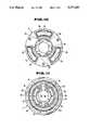
- FIG. 2is a plan view of a piston employed in the first embodiment of the shock absorber of FIG. 1;
- FIG. 3is a bottom view of the piston employed in the first embodiment of the shock absorber of FIG. 1;
- FIG. 4is a sectional view showing construction of a bottom valve employed in the first embodiment of the shock absorber of FIG. 1;
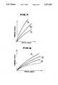
- FIG. 5is a graph showing relationship between a pressure difference of inner and outer grooves and a piston stroke speed, during piston rebounding stroke
- FIG. 6is a graph showing relationship between a pressure difference of the outer groove and a lower fluid chamber and the piston stroke speed
- FIG. 7is a graph showing relationship between a damping force generating in the piston rebounding stroke and the piston stroke speed
- FIG. 8is a graph showing relationship between a damping force generating in the piston bounding stroke and the piston stroke speed
- FIG. 9is a sectional view of the major part of the second embodiment of a variable damping characteristics shock absorber according to the present invention.
- FIG. 10is a plan view of a piston employed in the second embodiment of the shock absorber of FIG. 9;
- FIG. 11is a bottom view of the piston employed in the second embodiment of the shock absorber of FIG. 9.
- FIG. 12is a sectional view of the major part of the third embodiment of a variable damping characteristics shock absorber according to the present invention.
- the first embodiment of a shock absorberis formed as a double-action type shock absorber including an inner and an outer cylinder coaxially arranged with each other.
- FIG. 1only the inner cylinder 1 is disclosed.
- the double-action type shock absorber per seis generally well known in the art and thus this specification does not need to specifically disclose all construction thereof. Therefore, in the drawings, the outer cylinder is neglected for simplification of illustration on the drawings and associated disclosure.
- a piston assembly 2is slidingly or thrustingly disposed within the interior space of the inner cylinder 1 to define upper and lower fluid chambers A and B which are filled with a working fluid.
- the piston 2is fixed to the lower end of a piston rod 3 with a retainer 4, a washer 5, an upper disc valve 6, a piston body 7, a first lower disk valve 8, a second lower disc valve 9, a washer 10, a spring seat member 11 and a spring 12.
- the components set forth aboveform a piston assembly and are retained at the lower end portion of the piston rod 3 by means of a fastening nut 13.
- the piston body 7is formed with an axially extending fluid passages 7a and 7e.
- the fluid passage 7ais oriented at a position closer to the outer periphery of the piston body than that of the fluid passage 7e. Therefore, in the following discussion, the fluid passage 7a will be referred to as an "outer axial passage” and the fluid passage 7e will be referred to as an "inner axial passage”.
- three outer axial passages 7aare formed with circumferential intervals.
- Each of the outer axial passages 7ais formed into an essentially arc-shaped configuration having a predetermined circumferential width, and has an upper end opening to a groove 7a' defined by continuous land 7b having a valve seat surface 7b'.
- the upper disc valve 6has circumferential edge portions seating on the seat surface 7b' of the land 7b.
- the upper disc valve 6 at a position completely closing the groove 7a'seats on the entire seat surface 7b'.
- the lower end of the outer axial passage 7ais directly exposed to the lower fluid chamber B, so that the working fluid in the lower fluid chamber is free to flow therewithin.
- the inner axial passages 7erespectively have circular cross sections.
- six inner axial passages 7eare circumferentially arranged with equal intervals, as shown in FIGS. 2 and 3.
- the upper end of each of inner axial passages 7eis directly exposed to the upper fluid chamber A via a clearance 7e' defined between the upper face of the piston body 7 and the upper disc valve 6.
- the lower end of the inner axial passage 7eis open to an inner annular groove 7c which is defined between a central boss section 7g and an annular land 7f.
- the annular land 7ffurther defines an outer annular groove 7d with an annular land 7h as particularly shown in FIGS. 1 and 3.
- the annular lands 7f and 7hrespectively define valve seat surfaces 7f' and 7h' for seating thereon the first lower disc valve 8.
- the first lower valve 8normally seats on the seat surfaces 7f' and 7h' for sealing the inner and outer grooves 7c and 7d and is subject to the fluid pressure in the upper fluid chamber A introduced into the inner axial passages 7e via the clearance 7e'.
- the piston rod 3is formed with an axially extending center opening 3b.
- the center opening 3bis communicated with the upper fluid chamber A via radially extending openings 3c.
- the radially extending openings 3cwill be hereafter referred to as "upper ports”.
- the center opening 3bis in fluid communication with the outer annular groove via radially extending opening 3d, an annular groove 3a and obliquely extending openings 7j which extends in oblique with respect to the axis of the piston rod 3.
- the radially extending openingswill be hereafter referred to as "lower ports”.
- a rotary valve member 15is rotatably disposed within the axially extending opening 3b for rotation thereabout.
- the rotary valve member 15is supported or maintained by upper and lower thrust bushings 16 and 17.
- the rotary valve member 15is fixed to the lower end of an actuator rod 18.
- the actuator rod 18is connected to a rotary actuator (not shown) for rotatingly driving the actuator rod 18 and thus drives the rotary valve member 15.
- the rotary actuatorhas been disclosed in U.S. Pat. No. 4,776,437, issued on Oct. 11, 1988 and assigned to the common assignee to the present invention, for example.
- the disclosure of U.S. Pat. No. 4,776,437is herein incorporated by reference for the sake of disclosure.
- the rotary valve member 15defines a lower end opened bore communicated with the center opening 3b of the piston rod 3.
- the rotary valve membershave a plurality of radially extending openings at an axial position corresponding to the position of the upper ports 3c.
- the radially extending openings of the rotary valve member 15have different diameters than adjacent ones so as to provide different fluid flow path areas at different angular positions.
- the rotary valve member 15is formed with smaller diameter openings 15b and a greater diameter openings 15c with 90° of angular intervals.
- one of the openings 15b and 15cis selectively aligned with the upper ports 3c for providing a different path area for fluid communication between the interior space of the rotary valve member 15 and the upper fluid chamber A.
- the interior space of the rotary valve member 15is in fluid communication with the center opening 3b of the piston rod 3 for defining a chamber C extending in the axial direction. Therefore, the chamber defined by the interior space of the rotary valve member 15 and the center opening 3b will be hereafter referred to as an "axial chamber".
- the rotary valve member 15is also formed with a plurality of radially extending openings at an axial position corresponding to the lower ports 3d.
- the shown embodimentis formed with openings 15d and 15e having different diameters.
- the opening 15dis adapted to be aligned with the lower ports 3d at the angular position of the rotary valve member 15 where the openings 15b are aligned with the upper ports 3c, and have a smaller diameter than that of the opening 15e.
- the nut 13is engaged with the threaded lower end of the piston rod.
- the nutdefines a lower end opened bore 13a through which the interior space of the central opening 3b of the piston rod 3 communicates with the lower fluid chamber B.
- a check valve assembly 14including an annular valve seat 14a fixed to the lower end of the nut 13, a valve disc 14b and a bias spring 14c, is disposed within the bore 13a.
- the valve disc 14bis normally biased toward the valve seat 14a by means of the bias spring 14c in order to permit fluid flow directed from the lower fluid chamber B to the upper fluid chamber A via the center opening 3b and to block fluid flow in the opposite direction.
- the spring seat 11is associated with the nut 13 for movement therealong.
- the spring seat 11has a cylindrical section 11a and an outwardly and essentially horizontal flange-like section 11b on which one end of the spring 12 is seated. The other end of the spring 12 is seated on the stepped section of the nut. Therefore, the spring seat 11 is normally biased upwardly.
- the second lower disc valve 9has its external diameter substantially corresponding to the outer diameter of the annular form seat surface 7f' and the flange-like section 11b of the spring seat 11. Therefore, the spring seat 11 is associated with the second lower disc valve 9 for exerting a biasing force of the spring 12 to the latter and thus exerting the spring load onto the first disc valve 8.
- a bottom valve assembly 20is fitted to the lower end of the inner cylinder 1 for controlling fluid communication between the lower fluid chamber B and an annular reservoir chamber D defined between the inner cylinder 1 and an outer cylinder 19.
- the bottom valve assembly 20includes a bottom fitting 20' rigidly fitted to the lower end of the inner cylinder 1.
- the bottom fitting 20'defines axial openings 20a and 20b for fluid communication between the lower fluid chamber B and a chamber E defined between the bottom fitting 20' and a bottom closure 25.
- the upper end of the axial opening 20aopens to an outer annular groove 21a defined between lands 21b and 21c, which outer annular groove is closed by an upper disc valve 21.
- a stopper washer 24Adjacent the upper disc valve 21 is provided a stopper washer 24 which restricts magnitude of deformation of the disc valve for defining maximum path area to be formed between the land 21c and the outer circumferential edge portion of the upper disc valve 21.
- the lower end of the axial opening 20ais exposed to the chamber E.
- the upper end of the axial opening 20bopens to an inter annular groove 21d which is in direct fluid communication with the lower fluid chamber B via a through opening 21e formed through the disc valve 21.
- the lower end of the axial opening 20bopens to an annular groove 22a defined between land 20c and a center bore 20f.
- a first lower disc valve 22seats on the land 20c for normally closing the annular groove 22a.
- a second lower disc valve 23 seating on an annular land 20dis placed in a spaced apart relationship with the first lower disc valve 22 via a spacer washer 23b.
- the land 20dis formed with a radially-extending groove 20e serving as flow restricting orifice.
- the chamber E defined in the bottom fitting 20'is communicated with the reservoir chamber D via an radial path 20g defined through the circumferentially extending cylindrical portion of the bottom fitting.
- shock absorberThe operation of the aforementioned first embodiment of the shock absorber will be discussed herebelow with respect to bounding and rebounding mode operations.
- the working fluid having a pressure higher than that in the lower fluid chamber Bbecomes active on the portion of the first lower disc valve 8 opposing to the inner annular groove 7c to cause deformation of the first and second disc valves 8 and 9 and fluid flow into the outer annular chamber 7d and subsequently into the lower fluid chamber B through an annular clearance defined between the circumferential edge portion of the first disc valve 8 and the seat surface 7h' of the land 7h.
- the other part of the working fluidflows into the axial chamber C via the upper ports 3c and the openings 15c or 15d which are aligned with the upper ports.
- the valve disc 14bsince the fluid pressure in the axial chamber C is held higher than that in the lower fluid chamber B, the valve disc 14b is tightly seated on the valve seat 14a for blocking fluid flow therethrough. Therefore, the fluid flows into the outer annular groove 7d via the opening 15d or 15e, the lower ports 3d, the annular groove 3a and the oblique passage 7j and subsequently flows into the lower fluid chamber B defined between the circumferential portion of the first disc valve 8 and the seat surface 7h' of the land 7h.
- the deformation magnitude of the first lower disc valve 8 at the portion corresponding to the seat surface 7f'is limited to provide greater flow restriction.
- Such flow restrictionmay be substantial while the pressure difference between the upper and lower fluid chambers A and B is relatively small. Since the pressure difference between the upper and lower fluid chambers is essentially proportional to the piston stroke, the
- the orificesare defined between the first disc valve 8 and the seat surface 7f' of the land 7f and between the first disc valve 8 and the seat surface 7h' of the land 7h in tandem fashion.
- these orificesare principally effective for generating a damping force for a relatively low pressure difference between the upper and lower fluid chambers A and B and thus for a small magnitude of deformation of the first disc valve 8.
- a greater pressure difference between the upper and lower fluid chambers A and Bis generated for causing a greater deformation magnitude of the first disc valve 8 therefore, the throttling effect of the orifices becomes smaller. Therefore, at this speed range, the orifice effect of the openings 15b or 15c and 15d or 15e is principally active for generating a damping force.
- FIG. 5shows pressure difference between the inner and outer grooves 7c and 7d in relation to piston stroke magnitude.
- the line ashows characteristics obtained at the angular position of the rotary valve member 15 where the openings 15c and 15e are aligned with the upper and lower ports 3c and 3d
- the line bshows characteristics obtained at the angular position of the rotary valve member 15 where the openings 15b and 15d are aligned with the upper and lower ports
- the line cshows characteristics obtained at the angular position of the rotary valve member where the upper and the lower ports are fully blocked.
- this pressure differenceexhibits an orifice effect at the orifice defined between the first lower disc valve 8 and the seat surface 7f' of the land 7f. Therefore, because of a substantial restriction of deformation by the spring force exerted through the second lower disc valve, a variation rate of the pressure difference is held small in the low piston stroke range. On the other hand, a variation rate of the pressure difference becomes greater according to an increase in piston stroke speed.
- the variation characteristics of the pressure difference obtained at the orifice between the inner and outer grooves 7c and 7dare close to linear characteristics. This tendency is increased as the piston stroke speed increases.
- FIG. 6shows a variation of pressure difference between the outer groove 7d and the lower fluid chamber B.
- a greater variation rate of the pressure differenceis caused at a low piston stroke speed range.
- the variation rate of the pressure differenceis reduced according to an increase in the piston stroke speed.
- the characteristics of the variation of the variation rate of the pressure difference at the intermediate and high piston stroke speed rangeis substantially linear.
- Part of the working fluidflows into the outer axial passage 7a for exerting fluid pressure to the corresponding portion of the upper disc valve 6 to cause deformation of the latter.
- an annular orificeis formed between the upper disc valve 6 and the seat surface 7b' of the land 7b for permitting fluid flow therethrough.
- the other part of the working fluidflows into the axial chamber C by shifting the valve disc 14b away from the valve seat 14a. Then, the working fluid in the axial chamber C flows through the openings 15b or 15c and the upper port 3c into the upper fluid chamber A.
- the increased fluid pressure in the lower fluid chamber Bacts on the first lower disc valve 22 for causing deformation to open an annular orifice between the mating surface of the disc valve and the seat surface 20c. Therefore, the working fluid pressure acts on the second lower disc valve 23. While the piston stroke speed is relatively low, the pressure difference between both sides of the second lower disc valve 23 is held small so as not to cause deformation of the disc valve. As a result, the second lower disc valve stays on the seat surface of the land 20d. Therefore, fluid flow is then permitted only through the radially extending groove 20e. Since the radially extending groove provides the flow restriction, a damping force is generated. On the other hand, at the intermediate and high piston stroke speed range, the pressure difference between both sides of the second lower disc valve 23 becomes substantial to cause deformation of the disc valve for forming an annular orifice to permit fluid flow into the chamber E.
- FIG. 9shows the second embodiment of a variable damping force shock absorber according to the present invention.
- the shown embodimentis differentiated from the foregoing first embodiment in the construction for establishing fluid communication between the axial chamber C and the annular groove 7d. Also, in the shown embodiment, the upper port and the associated radially extending opening are omitted. Therefore, the components and constructions common to the foregoing first embodiment will be represented by the same reference numerals as the former embodiment and will not be discussed in detail in order to avoid redundant discussion for clarity of the disclosure.
- the oblique passage 7j in the former embodimentis replaced with radially extending grooves 7m and 7n.
- the radially extending grooves 7m and 7nare constructed and arranged for establishing fluid communication with the ports 3c and 3d formed through the piston rod 3.
- the radially extending orifice 7mis in fluid communication with the inner annular groove 7c
- the radially extending orifice 7nis in fluid communication with the outer annular groove 7d.
- the high pressure fluid in the upper fluid chamber Aflows into the inner axial passage 7e via the clearance 7e' and subsequently into the inner annular groove 7c during a piston rebounding stroke.
- the working fluid in the annular groove 7cflows into the axial chamber C via the radially extending groove 7m and the port 3c.
- the fluid pressure in the axial chamber Cis higher than that in the lower fluid chamber B. Therefore, the valve disc 14b is held at the position tightly seated on the valve seat 14a. Therefore, the working fluid in the axial chamber C flows into the radially extending groove 7n via the radially extending opening 15c or 15d and the port 3d. Therefore, the fluid pressure is introduced into the outer annular chamber 7d.
- the part of the working fluidflows through the outer axial passage 7a and the orifice defined between the upper disc valve 6 and the seat surface 7b' of the land 7b.
- Another part of the working fluidflows into the axial chamber C by shifting the disc valve 14b away from the valve seat 14a.
- the fluid in the axial chamber Cflows into the radially extending groove 7m via the radially extending opening 15c or 15d and the port 3c and subsequently into the inner axial passage 7e via the inner annular groove 7c. Therefore, a linear variation of the damping characteristics can be obtained by the operation of the upper disc valve 6 and the bottom valve assembly 20 which is identical in construction to that in the former embodiment.
- FIG. 12shows the third and perhaps the best mode embodiment of a variable damping force shock absorber according to the present invention.
- the shown embodimenthas common components and constructions to the foregoing first embodiment.
- the common componentswill be represented by the same reference numerals to the first embodiment and will not be discussed in detail.
- the shown embodimentis differentiated from the first and second embodiments in the construction for establishing fluid communication between the axial chamber C and the outer annular groove 7d.
- the radially extending groove 7pis formed on the lower surface of the piston body 7.
- the radially extending groove 7pestablishes fluid communication between the outer annular groove 7d and an axially extending groove 7r which is in fluid communication with an upper end of an opened annular groove 7s.
- the annular groove 7sis in fluid communication with the axial chamber C.
- the piston rod 3is formed of upper and lower radially extending ports 3b at axially offset positions to each other. Both of the upper and lower ports 3b are in fluid communication with the upper fluid chamber A.
- the ports 3bare, in turn, in fluid communication with the axial chamber via radially extending openings 15a, 15b and 15c, 15d, in which the opening 15a has a different diameter than the opening 15b and the opening 15c has different diameter than the opening 15d.
- all of the openings 15a, 15b and 15c, 15dare aligned with the ports 3b, these openings may be aligned with or shifted away from the port 3b for varying flow restriction provided therefore.
- the working fluidflows into the outer annular groove 7d from the upper fluid chamber via the ports 3b and the radial openings 15a or 15b and 15c or 15d during a piston rebounding stroke.
- This fluid pressurethus introduced into the outer annular groove 7d cooperates with the fluid pressure introduced into the inner annular groove 7c via the inner axial passage 7e for providing linear variation characteristics of the damping characteristics as that provided in the first embodiment.
- each openingcan be smaller than that in the former embodiments. Consequently, the rotary valve member can be constructed smaller for reducing the required force for rotatingly driving and positioning the same at the desired angular position. Also, since the radially extending groove 7p of the shown embodiment is an axially elongated groove, fluid communication can be assured even when the piston body and the piston rod tolerate.
Landscapes
- Engineering & Computer Science (AREA)
- General Engineering & Computer Science (AREA)
- Mechanical Engineering (AREA)
- Physics & Mathematics (AREA)
- Fluid Mechanics (AREA)
- Fluid-Damping Devices (AREA)
Abstract
Description
Claims (2)
Priority Applications (1)
| Application Number | Priority Date | Filing Date | Title |
|---|---|---|---|
| US08/044,086US5277283A (en) | 1988-09-19 | 1993-04-06 | Variable damping-characteristics shock absorber with adjustable orifice construction variable of fluid flow restriction depending upon fluid pressure difference |
Applications Claiming Priority (7)
| Application Number | Priority Date | Filing Date | Title |
|---|---|---|---|
| JP23461188AJP2752652B2 (en) | 1988-09-19 | 1988-09-19 | Variable damping force type hydraulic shock absorber |
| JP23461088AJP2752651B2 (en) | 1988-09-19 | 1988-09-19 | Variable damping force type hydraulic shock absorber |
| JP63-234610 | 1988-09-19 | ||
| JP63-234611 | 1988-09-19 | ||
| US40826189A | 1989-09-18 | 1989-09-18 | |
| US76349691A | 1991-09-23 | 1991-09-23 | |
| US08/044,086US5277283A (en) | 1988-09-19 | 1993-04-06 | Variable damping-characteristics shock absorber with adjustable orifice construction variable of fluid flow restriction depending upon fluid pressure difference |
Related Parent Applications (1)
| Application Number | Title | Priority Date | Filing Date |
|---|---|---|---|
| US76349691AContinuation | 1988-09-19 | 1991-09-23 |
Publications (1)
| Publication Number | Publication Date |
|---|---|
| US5277283Atrue US5277283A (en) | 1994-01-11 |
Family
ID=27529937
Family Applications (1)
| Application Number | Title | Priority Date | Filing Date |
|---|---|---|---|
| US08/044,086Expired - LifetimeUS5277283A (en) | 1988-09-19 | 1993-04-06 | Variable damping-characteristics shock absorber with adjustable orifice construction variable of fluid flow restriction depending upon fluid pressure difference |
Country Status (1)
| Country | Link |
|---|---|
| US (1) | US5277283A (en) |
Cited By (61)
| Publication number | Priority date | Publication date | Assignee | Title |
|---|---|---|---|---|
| US5456480A (en)* | 1994-06-06 | 1995-10-10 | Rockshox, Inc. | Fork suspension with variable hydraulic damping |
| US5706919A (en)* | 1996-07-29 | 1998-01-13 | General Motors Corporation | Alternating state pressure regulation valved damper |
| US5769193A (en)* | 1994-12-22 | 1998-06-23 | Fichtel & Sachs Ag | Telescoping vibration damper |
| US5829556A (en)* | 1994-11-14 | 1998-11-03 | Jarret | Damper device, of the type with hydrostatic compression of elastomer, and its applications |
| US5848675A (en)* | 1996-10-03 | 1998-12-15 | Answer Products, Inc. | Damping apparatus for bicycle forks |
| US6050583A (en)* | 1997-01-13 | 2000-04-18 | Bohn; David D. | Electronically controlled bicycle suspension apparatus |
| WO2000044579A1 (en)* | 1999-02-01 | 2000-08-03 | Gabriel Ride Control Products, Inc. | Improved shock absorber |
| US6105987A (en)* | 1997-12-17 | 2000-08-22 | Rockshox, Inc. | Valve mechanism for damping system |
| US6241060B1 (en)* | 1996-10-03 | 2001-06-05 | Answer Products, Inc. | Oil damped fork |
| US6343677B2 (en)* | 1999-02-01 | 2002-02-05 | Gabriel Ride Control Products, Inc. | Shock absorber |
| US6352145B1 (en) | 1998-10-07 | 2002-03-05 | Tenneco Automotive Inc. | Stroke dependent damping |
| US6464053B1 (en) | 1999-07-26 | 2002-10-15 | Tenneco Automotive Operating Company, Inc. | Single piece piston |
| US6474454B2 (en)* | 2000-05-31 | 2002-11-05 | Tokico Ltd. | Damping force control type hydraulic shock absorber |
| US6510929B1 (en)* | 1999-11-29 | 2003-01-28 | The Board Of Regents Of The University And Community College System Of Nevada | Controllable magneto-rheological fluid damper |
| US6581948B2 (en) | 2001-08-30 | 2003-06-24 | Fox Factory, Inc. | Inertia valve shock absorber |
| US6604751B2 (en) | 2001-08-30 | 2003-08-12 | Fox Factory, Inc. | Inertia valve shock absorber |
| US20030213662A1 (en)* | 2001-08-30 | 2003-11-20 | Fox Robert C. | Inertia valve shock absorber |
| US6786498B1 (en)* | 2003-04-28 | 2004-09-07 | Giant Manufacturing Co., Ltd. | Shock absorbing device for a bicycle |
| US20040222056A1 (en)* | 2001-08-30 | 2004-11-11 | Fox Robert C. | Inertia valve shock absorber |
| US20050150731A1 (en)* | 2003-07-07 | 2005-07-14 | Gregory Hitchcock | Controllable compressible fluid damper |
| US20060016649A1 (en)* | 2004-04-02 | 2006-01-26 | University Of Nevada | Controllable magneto-rheological fluid devices for motion-damping |
| US20060071380A1 (en)* | 2002-11-05 | 2006-04-06 | Toyo Tire & Rubber Co., Ltd. | Vibration isolator |
| US20060266602A1 (en)* | 2003-08-12 | 2006-11-30 | Robertson Graeme K | Shock absorber assembly |
| US20070119670A1 (en)* | 2001-08-30 | 2007-05-31 | Fox Factory, Inc. | Inertia valve fluid damper with reservoir positioned blowoff valve |
| EP1876090A1 (en)* | 2006-07-07 | 2008-01-09 | Yamaha Hatsudoki Kabushiki Kaisha | Hydraulic shock absorber and motorcycle |
| US20110209957A1 (en)* | 2010-02-26 | 2011-09-01 | Masahiro Ashiba | Shock absorber |
| US20130161138A1 (en)* | 2005-08-11 | 2013-06-27 | Eko Sport, Inc. | Valve for shock absorbers |
| US20130313056A1 (en)* | 2012-05-10 | 2013-11-28 | Fox Factory, Inc. | Method and apparatus for an adjustable damper |
| US8607942B2 (en) | 2006-04-02 | 2013-12-17 | Fox Factory, Inc. | Suspension damper having inertia valve and user adjustable pressure-relief |
| US8820495B2 (en) | 2010-07-21 | 2014-09-02 | King Shock Technology, Inc. | Adjustable internal bypass shock absorber featuring a fluid flow regulator |
| US9038791B2 (en) | 2009-01-07 | 2015-05-26 | Fox Factory, Inc. | Compression isolator for a suspension damper |
| US9353818B2 (en) | 2009-01-07 | 2016-05-31 | Fox Factory, Inc. | Remotely operated bypass for a suspension damper |
| US20170016260A1 (en)* | 2014-03-12 | 2017-01-19 | Samsung Precision Ind.Co., Ltd | Variable shock-absorbing damper for furniture hinge, with built-in pressure control means |
| US9616728B2 (en) | 2009-01-07 | 2017-04-11 | Fox Factory, Inc. | Bypass for a suspension damper |
| US9663181B2 (en) | 2009-01-07 | 2017-05-30 | Fox Factory, Inc. | Method and apparatus for an adjustable damper |
| US10036443B2 (en) | 2009-03-19 | 2018-07-31 | Fox Factory, Inc. | Methods and apparatus for suspension adjustment |
| US10040329B2 (en) | 2009-01-07 | 2018-08-07 | Fox Factory, Inc. | Method and apparatus for an adjustable damper |
| US10047817B2 (en) | 2009-01-07 | 2018-08-14 | Fox Factory, Inc. | Method and apparatus for an adjustable damper |
| US10060499B2 (en) | 2009-01-07 | 2018-08-28 | Fox Factory, Inc. | Method and apparatus for an adjustable damper |
| US10072724B2 (en) | 2008-08-25 | 2018-09-11 | Fox Factory, Inc. | Methods and apparatus for suspension lock out and signal generation |
| US10086670B2 (en) | 2009-03-19 | 2018-10-02 | Fox Factory, Inc. | Methods and apparatus for suspension set up |
| US10180171B2 (en) | 2009-10-13 | 2019-01-15 | Fox Factory, Inc. | Suspension system |
| US20190186583A1 (en)* | 2016-08-26 | 2019-06-20 | Swansea University | Valve arrangement and damper comprising the valve arrangement |
| US10406883B2 (en) | 2009-10-13 | 2019-09-10 | Fox Factory, Inc. | Methods and apparatus for controlling a fluid damper |
| US10443671B2 (en) | 2009-01-07 | 2019-10-15 | Fox Factory, Inc. | Remotely operated bypass for a suspension damper |
| US10556477B2 (en) | 2009-01-07 | 2020-02-11 | Fox Factory, Inc. | Suspension damper with by-pass valves |
| US10591015B2 (en) | 2009-03-19 | 2020-03-17 | Fox Factory, Inc. | Methods and apparatus for suspension adjustment |
| US10677309B2 (en) | 2011-05-31 | 2020-06-09 | Fox Factory, Inc. | Methods and apparatus for position sensitive suspension damping |
| US10697514B2 (en) | 2010-01-20 | 2020-06-30 | Fox Factory, Inc. | Remotely operated bypass for a suspension damper |
| US10718397B2 (en) | 2011-03-03 | 2020-07-21 | Fox Factory, Inc. | Cooler for a suspension damper |
| US10737546B2 (en) | 2016-04-08 | 2020-08-11 | Fox Factory, Inc. | Electronic compression and rebound control |
| US10821795B2 (en) | 2009-01-07 | 2020-11-03 | Fox Factory, Inc. | Method and apparatus for an adjustable damper |
| US11021204B2 (en) | 2008-11-25 | 2021-06-01 | Fox Factory, Inc. | Seat post |
| US11255399B2 (en)* | 2018-03-14 | 2022-02-22 | Zf Friedrichshafen Ag | Damping valve for a vibration damper |
| US11268589B2 (en)* | 2017-11-24 | 2022-03-08 | Martin Zimmer | Cylinder-piston unit with load-dependent throttle |
| US11279199B2 (en) | 2012-01-25 | 2022-03-22 | Fox Factory, Inc. | Suspension damper with by-pass valves |
| US11299233B2 (en) | 2009-01-07 | 2022-04-12 | Fox Factory, Inc. | Method and apparatus for an adjustable damper |
| US11306798B2 (en) | 2008-05-09 | 2022-04-19 | Fox Factory, Inc. | Position sensitive suspension damping with an active valve |
| US11413924B2 (en) | 2009-03-19 | 2022-08-16 | Fox Factory, Inc. | Methods and apparatus for selective spring pre-load adjustment |
| US11866110B2 (en) | 2010-07-02 | 2024-01-09 | Fox Factory, Inc. | Lever assembly for positive lock adjustable seat post |
| US12122205B2 (en) | 2009-01-07 | 2024-10-22 | Fox Factory, Inc. | Active valve for an internal bypass |
Citations (24)
| Publication number | Priority date | Publication date | Assignee | Title |
|---|---|---|---|---|
| AU56846A (en)* | 1946-01-17 | 1948-05-20 | Johns & Waygood Limited | Improvements in and connected with self-levelling means for electric lifts |
| US2546051A (en)* | 1950-01-05 | 1951-03-20 | Patent Dev Company | Shock absorber |
| DE951693C (en)* | 1952-01-11 | 1956-10-31 | Fichtel & Sachs Ag | Lamellar valve, especially for shock absorbers |
| GB1009252A (en)* | 1962-04-04 | 1965-11-10 | Arie Adrianus De Koning | Shock absorbers |
| DE1287455B (en)* | 1969-01-16 | |||
| GB1539652A (en)* | 1976-07-09 | 1979-01-31 | Monroe Auto Equipment Co | Base valve assembly for wheel suspension strut shock absorber |
| US4203507A (en)* | 1977-04-29 | 1980-05-20 | Honda Giken Kogyo Kabushiki Kaisha | Shock absorber |
| US4352417A (en)* | 1980-10-03 | 1982-10-05 | Ford Motor Company | Control valve for shock absorber pistons and the like |
| GB2111168A (en)* | 1981-11-06 | 1983-06-29 | Tokico Ltd | Hydraulic damper with bypass |
| GB2159917A (en)* | 1984-06-09 | 1985-12-11 | Boge Gmbh | An hydraulic damper with adjustable valve |
| US4561524A (en)* | 1982-02-01 | 1985-12-31 | Kayaba Kogyo Kabushiki Kaisha | Damping force regulation device for telescope shock absorber |
| DE3425988A1 (en)* | 1984-07-14 | 1986-01-23 | Boge Gmbh, 5208 Eitorf | Adjustable hydraulic shock absorber |
| EP0174119A2 (en)* | 1984-09-04 | 1986-03-12 | General Motors Corporation | Hydraulic damping unit |
| JPS61164836A (en)* | 1985-01-18 | 1986-07-25 | Toyo Ink Mfg Co Ltd | Recording method |
| EP0196030A2 (en)* | 1985-03-22 | 1986-10-01 | Toyota Jidosha Kabushiki Kaisha | Hydraulic buffer |
| EP0207409A2 (en)* | 1985-07-02 | 1987-01-07 | Bayerische Motoren Werke Aktiengesellschaft, Patentabteilung AJ-3 | Valve system for an adjustable hydraulic damper |
| DE3532293A1 (en)* | 1985-09-11 | 1987-03-19 | Fichtel & Sachs Ag | VIBRATION DAMPER WITH VARIABLE DAMPING FORCE |
| JPS62278333A (en)* | 1986-05-27 | 1987-12-03 | Kayaba Ind Co Ltd | hydraulic shock absorber |
| US4721130A (en)* | 1985-12-27 | 1988-01-26 | Toyota Jidosha Kabushiki Kaisha | Valve structure of hydraulic buffer |
| JPS6323461A (en)* | 1986-07-16 | 1988-01-30 | Ricoh Co Ltd | Output control method for picture reader |
| JPS6323460A (en)* | 1986-07-16 | 1988-01-30 | Canon Inc | Picture reader |
| US4724937A (en)* | 1984-09-04 | 1988-02-16 | General Motors Corporation | Hydraulic damper for vehicles with variable deflected disk piston valving |
| US4826207A (en)* | 1987-01-16 | 1989-05-02 | Honda Giken Kogyo Kabushiki Kaisha | Compound suspension system |
| US4905799A (en)* | 1988-04-04 | 1990-03-06 | Atsugi Motor Parts Company, Limited | Shock absorber |
- 1993
- 1993-04-06USUS08/044,086patent/US5277283A/ennot_activeExpired - Lifetime
Patent Citations (24)
| Publication number | Priority date | Publication date | Assignee | Title |
|---|---|---|---|---|
| DE1287455B (en)* | 1969-01-16 | |||
| AU56846A (en)* | 1946-01-17 | 1948-05-20 | Johns & Waygood Limited | Improvements in and connected with self-levelling means for electric lifts |
| US2546051A (en)* | 1950-01-05 | 1951-03-20 | Patent Dev Company | Shock absorber |
| DE951693C (en)* | 1952-01-11 | 1956-10-31 | Fichtel & Sachs Ag | Lamellar valve, especially for shock absorbers |
| GB1009252A (en)* | 1962-04-04 | 1965-11-10 | Arie Adrianus De Koning | Shock absorbers |
| GB1539652A (en)* | 1976-07-09 | 1979-01-31 | Monroe Auto Equipment Co | Base valve assembly for wheel suspension strut shock absorber |
| US4203507A (en)* | 1977-04-29 | 1980-05-20 | Honda Giken Kogyo Kabushiki Kaisha | Shock absorber |
| US4352417A (en)* | 1980-10-03 | 1982-10-05 | Ford Motor Company | Control valve for shock absorber pistons and the like |
| GB2111168A (en)* | 1981-11-06 | 1983-06-29 | Tokico Ltd | Hydraulic damper with bypass |
| US4561524A (en)* | 1982-02-01 | 1985-12-31 | Kayaba Kogyo Kabushiki Kaisha | Damping force regulation device for telescope shock absorber |
| GB2159917A (en)* | 1984-06-09 | 1985-12-11 | Boge Gmbh | An hydraulic damper with adjustable valve |
| DE3425988A1 (en)* | 1984-07-14 | 1986-01-23 | Boge Gmbh, 5208 Eitorf | Adjustable hydraulic shock absorber |
| EP0174119A2 (en)* | 1984-09-04 | 1986-03-12 | General Motors Corporation | Hydraulic damping unit |
| US4724937A (en)* | 1984-09-04 | 1988-02-16 | General Motors Corporation | Hydraulic damper for vehicles with variable deflected disk piston valving |
| JPS61164836A (en)* | 1985-01-18 | 1986-07-25 | Toyo Ink Mfg Co Ltd | Recording method |
| EP0196030A2 (en)* | 1985-03-22 | 1986-10-01 | Toyota Jidosha Kabushiki Kaisha | Hydraulic buffer |
| EP0207409A2 (en)* | 1985-07-02 | 1987-01-07 | Bayerische Motoren Werke Aktiengesellschaft, Patentabteilung AJ-3 | Valve system for an adjustable hydraulic damper |
| DE3532293A1 (en)* | 1985-09-11 | 1987-03-19 | Fichtel & Sachs Ag | VIBRATION DAMPER WITH VARIABLE DAMPING FORCE |
| US4721130A (en)* | 1985-12-27 | 1988-01-26 | Toyota Jidosha Kabushiki Kaisha | Valve structure of hydraulic buffer |
| JPS62278333A (en)* | 1986-05-27 | 1987-12-03 | Kayaba Ind Co Ltd | hydraulic shock absorber |
| JPS6323461A (en)* | 1986-07-16 | 1988-01-30 | Ricoh Co Ltd | Output control method for picture reader |
| JPS6323460A (en)* | 1986-07-16 | 1988-01-30 | Canon Inc | Picture reader |
| US4826207A (en)* | 1987-01-16 | 1989-05-02 | Honda Giken Kogyo Kabushiki Kaisha | Compound suspension system |
| US4905799A (en)* | 1988-04-04 | 1990-03-06 | Atsugi Motor Parts Company, Limited | Shock absorber |
Cited By (150)
| Publication number | Priority date | Publication date | Assignee | Title |
|---|---|---|---|---|
| US5456480A (en)* | 1994-06-06 | 1995-10-10 | Rockshox, Inc. | Fork suspension with variable hydraulic damping |
| EP0686547A2 (en) | 1994-06-06 | 1995-12-13 | Rockshox, Inc. | Fork suspension with variable hydraulic damping |
| EP0686547A3 (en)* | 1994-06-06 | 1996-03-13 | Rockshox Inc | Fork suspension with variable hydraulic damping |
| US5829556A (en)* | 1994-11-14 | 1998-11-03 | Jarret | Damper device, of the type with hydrostatic compression of elastomer, and its applications |
| US5769193A (en)* | 1994-12-22 | 1998-06-23 | Fichtel & Sachs Ag | Telescoping vibration damper |
| US5706919A (en)* | 1996-07-29 | 1998-01-13 | General Motors Corporation | Alternating state pressure regulation valved damper |
| US5848675A (en)* | 1996-10-03 | 1998-12-15 | Answer Products, Inc. | Damping apparatus for bicycle forks |
| US6241060B1 (en)* | 1996-10-03 | 2001-06-05 | Answer Products, Inc. | Oil damped fork |
| US6360858B2 (en) | 1996-10-03 | 2002-03-26 | Answer Products, Inc. | Damping apparatus for bicycle forks |
| US6050583A (en)* | 1997-01-13 | 2000-04-18 | Bohn; David D. | Electronically controlled bicycle suspension apparatus |
| US6105987A (en)* | 1997-12-17 | 2000-08-22 | Rockshox, Inc. | Valve mechanism for damping system |
| US6505719B2 (en) | 1998-05-18 | 2003-01-14 | Answer Products, Inc. | Damping apparatus for bicycle forks |
| US6352145B1 (en) | 1998-10-07 | 2002-03-05 | Tenneco Automotive Inc. | Stroke dependent damping |
| WO2000044579A1 (en)* | 1999-02-01 | 2000-08-03 | Gabriel Ride Control Products, Inc. | Improved shock absorber |
| US6343677B2 (en)* | 1999-02-01 | 2002-02-05 | Gabriel Ride Control Products, Inc. | Shock absorber |
| US6213262B1 (en)* | 1999-02-01 | 2001-04-10 | Gabriel Ride Control Products, Inc. | Shock absorber |
| US6464053B1 (en) | 1999-07-26 | 2002-10-15 | Tenneco Automotive Operating Company, Inc. | Single piece piston |
| US6510929B1 (en)* | 1999-11-29 | 2003-01-28 | The Board Of Regents Of The University And Community College System Of Nevada | Controllable magneto-rheological fluid damper |
| US6474454B2 (en)* | 2000-05-31 | 2002-11-05 | Tokico Ltd. | Damping force control type hydraulic shock absorber |
| US20070227844A1 (en)* | 2001-08-30 | 2007-10-04 | Fox Factory, Inc. | Bicycle Suspension Assembly With Inertia Valve and G-Threshold |
| US7506884B2 (en) | 2001-08-30 | 2009-03-24 | Fox Factory, Inc. | Bicycle suspension assembly with inertia valve and blow-off |
| US20030213662A1 (en)* | 2001-08-30 | 2003-11-20 | Fox Robert C. | Inertia valve shock absorber |
| US6581948B2 (en) | 2001-08-30 | 2003-06-24 | Fox Factory, Inc. | Inertia valve shock absorber |
| US20040222056A1 (en)* | 2001-08-30 | 2004-11-11 | Fox Robert C. | Inertia valve shock absorber |
| US10316924B2 (en) | 2001-08-30 | 2019-06-11 | Fox Factory, Inc. | Front bicycle suspension assembly with inertia valve |
| US9657804B2 (en) | 2001-08-30 | 2017-05-23 | Fox Factory, Inc. | Front bicycle suspension assembly with inertia valve |
| US8770360B2 (en) | 2001-08-30 | 2014-07-08 | Fox Factory, Inc. | Front bicycle suspension assembly with inertia valve |
| US7128192B2 (en) | 2001-08-30 | 2006-10-31 | Fox Factory, Inc. | Inertia valve shock absorber |
| US11346422B2 (en) | 2001-08-30 | 2022-05-31 | Fox Factory, Inc. | Front bicycle suspension assembly with inertia valve |
| US20070119670A1 (en)* | 2001-08-30 | 2007-05-31 | Fox Factory, Inc. | Inertia valve fluid damper with reservoir positioned blowoff valve |
| US7261194B2 (en) | 2001-08-30 | 2007-08-28 | Fox Factory, Inc. | Bicycle suspension assembly with isolated inertia mass |
| US7273137B2 (en) | 2001-08-30 | 2007-09-25 | Fox Factory, Inc. | Inertia valve shock absorber |
| US8297417B2 (en) | 2001-08-30 | 2012-10-30 | Fox Factory, Inc. | Front bicycle suspension assembly with inertia valve |
| US20070228691A1 (en)* | 2001-08-30 | 2007-10-04 | Fox Factory, Inc. | Front Bicycle Suspension Assembly With Inertia Valve |
| US20070227845A1 (en)* | 2001-08-30 | 2007-10-04 | Fox Factory, Inc. | Bicycle Suspension Assembly With Inertia Valve and Blow-Off |
| US20070296163A1 (en)* | 2001-08-30 | 2007-12-27 | Fox Factory, Inc. | Inertia Valve Vehicle Suspension Assembly |
| US20110031076A1 (en)* | 2001-08-30 | 2011-02-10 | Fox Robert C | Front bicycle suspension assembly with inertia valve |
| US7766135B2 (en) | 2001-08-30 | 2010-08-03 | Fox Factory, Inc. | Front bicycle suspension assembly with inertia valve |
| US7520372B2 (en) | 2001-08-30 | 2009-04-21 | Fox Factory, Inc. | Inertia valve vehicle suspension assembly |
| US7448638B2 (en) | 2001-08-30 | 2008-11-11 | Fox Factory, Inc. | Front bicycle suspension assembly with inertia valve |
| US7484603B2 (en) | 2001-08-30 | 2009-02-03 | Fox Factory, Inc. | Shock absorber with electronic control |
| US7490705B2 (en) | 2001-08-30 | 2009-02-17 | Fox Factory, Inc. | Bicycle suspension assembly including inertia valve and gas spring |
| US6604751B2 (en) | 2001-08-30 | 2003-08-12 | Fox Factory, Inc. | Inertia valve shock absorber |
| US20060071380A1 (en)* | 2002-11-05 | 2006-04-06 | Toyo Tire & Rubber Co., Ltd. | Vibration isolator |
| US6786498B1 (en)* | 2003-04-28 | 2004-09-07 | Giant Manufacturing Co., Ltd. | Shock absorbing device for a bicycle |
| US7422092B2 (en) | 2003-07-07 | 2008-09-09 | Gregory Hitchcock | Controllable compressible fluid damper |
| US20050150731A1 (en)* | 2003-07-07 | 2005-07-14 | Gregory Hitchcock | Controllable compressible fluid damper |
| USRE44609E1 (en)* | 2003-08-12 | 2013-11-26 | Graeme Kershaw Robertson | Shock absorber assembly |
| US20060266602A1 (en)* | 2003-08-12 | 2006-11-30 | Robertson Graeme K | Shock absorber assembly |
| US7513490B2 (en)* | 2003-08-12 | 2009-04-07 | Graeme Kershaw Robertson | Shock absorber assembly |
| US7364022B2 (en) | 2004-04-02 | 2008-04-29 | University Of Nevada | Controllable magneto-rheological fluid devices for motion-damping |
| US20060016649A1 (en)* | 2004-04-02 | 2006-01-26 | University Of Nevada | Controllable magneto-rheological fluid devices for motion-damping |
| US9322449B2 (en)* | 2005-08-11 | 2016-04-26 | Eko Sport, Inc. | Valve for shock absorbers |
| US20130161138A1 (en)* | 2005-08-11 | 2013-06-27 | Eko Sport, Inc. | Valve for shock absorbers |
| US11085503B2 (en) | 2006-04-02 | 2021-08-10 | Fox Factory, Inc. | Suspension damper having inertia valve and user adjustable pressure-relief |
| US9261163B2 (en) | 2006-04-02 | 2016-02-16 | Fox Factory, Inc. | Suspension damper having inertia valve and user adjustable pressure-relief |
| US8607942B2 (en) | 2006-04-02 | 2013-12-17 | Fox Factory, Inc. | Suspension damper having inertia valve and user adjustable pressure-relief |
| US10359092B2 (en) | 2006-04-02 | 2019-07-23 | Fox Factory, Inc. | Suspension damper having inertia valve and user adjustable pressure-relief |
| US9746049B2 (en) | 2006-04-02 | 2017-08-29 | Fox Factory, Inc. | Suspension damper having inertia valve and user adjustable pressure-relief |
| EP1876090A1 (en)* | 2006-07-07 | 2008-01-09 | Yamaha Hatsudoki Kabushiki Kaisha | Hydraulic shock absorber and motorcycle |
| US11306798B2 (en) | 2008-05-09 | 2022-04-19 | Fox Factory, Inc. | Position sensitive suspension damping with an active valve |
| US11162555B2 (en) | 2008-08-25 | 2021-11-02 | Fox Factory, Inc. | Methods and apparatus for suspension lock out and signal generation |
| US10550909B2 (en) | 2008-08-25 | 2020-02-04 | Fox Factory, Inc. | Methods and apparatus for suspension lock out and signal generation |
| US10072724B2 (en) | 2008-08-25 | 2018-09-11 | Fox Factory, Inc. | Methods and apparatus for suspension lock out and signal generation |
| US11021204B2 (en) | 2008-11-25 | 2021-06-01 | Fox Factory, Inc. | Seat post |
| US11897571B2 (en) | 2008-11-25 | 2024-02-13 | Fox Factory, Inc. | Seat post |
| US10160511B2 (en) | 2009-01-07 | 2018-12-25 | Fox Factory, Inc. | Method and apparatus for an adjustable damper |
| US10556477B2 (en) | 2009-01-07 | 2020-02-11 | Fox Factory, Inc. | Suspension damper with by-pass valves |
| US10047817B2 (en) | 2009-01-07 | 2018-08-14 | Fox Factory, Inc. | Method and apparatus for an adjustable damper |
| US10060499B2 (en) | 2009-01-07 | 2018-08-28 | Fox Factory, Inc. | Method and apparatus for an adjustable damper |
| US12377699B2 (en) | 2009-01-07 | 2025-08-05 | Fox Factory, Inc. | Method and apparatus for an adjustable damper |
| US12371122B2 (en) | 2009-01-07 | 2025-07-29 | Fox Factory, Inc. | Method and apparatus for an adjustable damper |
| US12257871B2 (en) | 2009-01-07 | 2025-03-25 | Fox Factory, Inc. | Method and apparatus for an adjustable damper |
| US10094443B2 (en) | 2009-01-07 | 2018-10-09 | Fox Factory, Inc. | Bypass for a suspension damper |
| US9784333B2 (en) | 2009-01-07 | 2017-10-10 | Fox Factory, Inc. | Compression isolator for a suspension damper |
| US12134293B2 (en) | 2009-01-07 | 2024-11-05 | Fox Factory, Inc. | Method and apparatus for an adjustable damper |
| US9663181B2 (en) | 2009-01-07 | 2017-05-30 | Fox Factory, Inc. | Method and apparatus for an adjustable damper |
| US12122205B2 (en) | 2009-01-07 | 2024-10-22 | Fox Factory, Inc. | Active valve for an internal bypass |
| US12091122B2 (en) | 2009-01-07 | 2024-09-17 | Fox Factory, Inc. | Method and apparatus for an adjustable damper |
| US10336148B2 (en) | 2009-01-07 | 2019-07-02 | Fox Factory, Inc. | Method and apparatus for an adjustable damper |
| US10336149B2 (en) | 2009-01-07 | 2019-07-02 | Fox Factory, Inc. | Method and apparatus for an adjustable damper |
| US9616728B2 (en) | 2009-01-07 | 2017-04-11 | Fox Factory, Inc. | Bypass for a suspension damper |
| US10400847B2 (en) | 2009-01-07 | 2019-09-03 | Fox Factory, Inc. | Compression isolator for a suspension damper |
| US12044286B2 (en) | 2009-01-07 | 2024-07-23 | Fox Factory, Inc. | Compression isolator for a suspension damper |
| US10415662B2 (en) | 2009-01-07 | 2019-09-17 | Fox Factory, Inc. | Remotely operated bypass for a suspension damper |
| US10443671B2 (en) | 2009-01-07 | 2019-10-15 | Fox Factory, Inc. | Remotely operated bypass for a suspension damper |
| US11976706B2 (en) | 2009-01-07 | 2024-05-07 | Fox Factory, Inc. | Remotely operated bypass for a suspension damper |
| US11299233B2 (en) | 2009-01-07 | 2022-04-12 | Fox Factory, Inc. | Method and apparatus for an adjustable damper |
| US10040329B2 (en) | 2009-01-07 | 2018-08-07 | Fox Factory, Inc. | Method and apparatus for an adjustable damper |
| US10670106B2 (en) | 2009-01-07 | 2020-06-02 | Fox Factory, Inc. | Method and apparatus for an adjustable damper |
| US11890908B2 (en) | 2009-01-07 | 2024-02-06 | Fox Factory, Inc. | Method and apparatus for an adjustable damper |
| US11866120B2 (en) | 2009-01-07 | 2024-01-09 | Fox Factory, Inc. | Method and apparatus for an adjustable damper |
| US11794543B2 (en) | 2009-01-07 | 2023-10-24 | Fox Factory, Inc. | Method and apparatus for an adjustable damper |
| US10723409B2 (en) | 2009-01-07 | 2020-07-28 | Fox Factory, Inc. | Method and apparatus for an adjustable damper |
| US11660924B2 (en) | 2009-01-07 | 2023-05-30 | Fox Factory, Inc. | Method and apparatus for an adjustable damper |
| US11549565B2 (en) | 2009-01-07 | 2023-01-10 | Fox Factory, Inc. | Method and apparatus for an adjustable damper |
| US11519477B2 (en) | 2009-01-07 | 2022-12-06 | Fox Factory, Inc. | Compression isolator for a suspension damper |
| US10781879B2 (en) | 2009-01-07 | 2020-09-22 | Fox Factory, Inc. | Bypass for a suspension damper |
| US10800220B2 (en) | 2009-01-07 | 2020-10-13 | Fox Factory, Inc. | Method and apparatus for an adjustable damper |
| US10807433B2 (en) | 2009-01-07 | 2020-10-20 | Fox Factory, Inc. | Method and apparatus for an adjustable damper |
| US10814689B2 (en) | 2009-01-07 | 2020-10-27 | Fox Factory, Inc. | Method and apparatus for an adjustable damper |
| US10821795B2 (en) | 2009-01-07 | 2020-11-03 | Fox Factory, Inc. | Method and apparatus for an adjustable damper |
| US11499601B2 (en) | 2009-01-07 | 2022-11-15 | Fox Factory, Inc. | Remotely operated bypass for a suspension damper |
| US11408482B2 (en) | 2009-01-07 | 2022-08-09 | Fox Factory, Inc. | Bypass for a suspension damper |
| US9366307B2 (en) | 2009-01-07 | 2016-06-14 | Fox Factory, Inc. | Compression isolator for a suspension damper |
| US9353818B2 (en) | 2009-01-07 | 2016-05-31 | Fox Factory, Inc. | Remotely operated bypass for a suspension damper |
| US9038791B2 (en) | 2009-01-07 | 2015-05-26 | Fox Factory, Inc. | Compression isolator for a suspension damper |
| US11168758B2 (en) | 2009-01-07 | 2021-11-09 | Fox Factory, Inc. | Method and apparatus for an adjustable damper |
| US11173765B2 (en) | 2009-01-07 | 2021-11-16 | Fox Factory, Inc. | Method and apparatus for an adjustable damper |
| US10591015B2 (en) | 2009-03-19 | 2020-03-17 | Fox Factory, Inc. | Methods and apparatus for suspension adjustment |
| US11619278B2 (en) | 2009-03-19 | 2023-04-04 | Fox Factory, Inc. | Methods and apparatus for suspension adjustment |
| US10036443B2 (en) | 2009-03-19 | 2018-07-31 | Fox Factory, Inc. | Methods and apparatus for suspension adjustment |
| US10086670B2 (en) | 2009-03-19 | 2018-10-02 | Fox Factory, Inc. | Methods and apparatus for suspension set up |
| US12163569B2 (en) | 2009-03-19 | 2024-12-10 | Fox Factory, Inc. | Methods and apparatus for suspension adjustment |
| US12103349B2 (en) | 2009-03-19 | 2024-10-01 | Fox Factory, Inc. | Methods and apparatus for selective spring pre-load adjustment |
| US11920655B2 (en) | 2009-03-19 | 2024-03-05 | Fox Factory, Inc. | Methods and apparatus for suspension adjustment |
| US11655873B2 (en) | 2009-03-19 | 2023-05-23 | Fox Factory, Inc. | Methods and apparatus for suspension adjustment |
| US11413924B2 (en) | 2009-03-19 | 2022-08-16 | Fox Factory, Inc. | Methods and apparatus for selective spring pre-load adjustment |
| US10406883B2 (en) | 2009-10-13 | 2019-09-10 | Fox Factory, Inc. | Methods and apparatus for controlling a fluid damper |
| US11279198B2 (en) | 2009-10-13 | 2022-03-22 | Fox Factory, Inc. | Methods and apparatus for controlling a fluid damper |
| US10180171B2 (en) | 2009-10-13 | 2019-01-15 | Fox Factory, Inc. | Suspension system |
| US10731724B2 (en) | 2009-10-13 | 2020-08-04 | Fox Factory, Inc. | Suspension system |
| US12005755B2 (en) | 2009-10-13 | 2024-06-11 | Fox Factory, Inc. | Methods and apparatus for controlling a fluid damper |
| US11859690B2 (en) | 2009-10-13 | 2024-01-02 | Fox Factory, Inc. | Suspension system |
| US10697514B2 (en) | 2010-01-20 | 2020-06-30 | Fox Factory, Inc. | Remotely operated bypass for a suspension damper |
| US11708878B2 (en) | 2010-01-20 | 2023-07-25 | Fox Factory, Inc. | Remotely operated bypass for a suspension damper |
| US20110209957A1 (en)* | 2010-02-26 | 2011-09-01 | Masahiro Ashiba | Shock absorber |
| US11866110B2 (en) | 2010-07-02 | 2024-01-09 | Fox Factory, Inc. | Lever assembly for positive lock adjustable seat post |
| US8820495B2 (en) | 2010-07-21 | 2014-09-02 | King Shock Technology, Inc. | Adjustable internal bypass shock absorber featuring a fluid flow regulator |
| US12110944B2 (en) | 2011-03-03 | 2024-10-08 | Fox Factory, Inc. | Cooler for a suspension damper |
| US10718397B2 (en) | 2011-03-03 | 2020-07-21 | Fox Factory, Inc. | Cooler for a suspension damper |
| US10975929B2 (en) | 2011-03-03 | 2021-04-13 | Fox Factory, Inc. | Cooler for a suspension damper |
| US10677309B2 (en) | 2011-05-31 | 2020-06-09 | Fox Factory, Inc. | Methods and apparatus for position sensitive suspension damping |
| US11796028B2 (en) | 2011-05-31 | 2023-10-24 | Fox Factory, Inc. | Methods and apparatus for position sensitive suspension damping |
| US10759247B2 (en) | 2011-09-12 | 2020-09-01 | Fox Factory, Inc. | Methods and apparatus for suspension set up |
| US11958328B2 (en) | 2011-09-12 | 2024-04-16 | Fox Factory, Inc. | Methods and apparatus for suspension set up |
| US11760150B2 (en) | 2012-01-25 | 2023-09-19 | Fox Factory, Inc. | Suspension damper with by-pass valves |
| US11279199B2 (en) | 2012-01-25 | 2022-03-22 | Fox Factory, Inc. | Suspension damper with by-pass valves |
| US20130313056A1 (en)* | 2012-05-10 | 2013-11-28 | Fox Factory, Inc. | Method and apparatus for an adjustable damper |
| US10859133B2 (en) | 2012-05-10 | 2020-12-08 | Fox Factory, Inc. | Method and apparatus for an adjustable damper |
| US12038062B2 (en) | 2012-05-10 | 2024-07-16 | Fox Factory, Inc. | Method and apparatus for an adjustable damper |
| US10330171B2 (en)* | 2012-05-10 | 2019-06-25 | Fox Factory, Inc. | Method and apparatus for an adjustable damper |
| US11629774B2 (en) | 2012-05-10 | 2023-04-18 | Fox Factory, Inc. | Method and apparatus for an adjustable damper |
| US20170016260A1 (en)* | 2014-03-12 | 2017-01-19 | Samsung Precision Ind.Co., Ltd | Variable shock-absorbing damper for furniture hinge, with built-in pressure control means |
| US10094157B2 (en)* | 2014-03-12 | 2018-10-09 | Samsung Precision Ind. Co., Ltd | Variable shock-absorbing damper for furniture hinge, with built-in pressure control means |
| US10737546B2 (en) | 2016-04-08 | 2020-08-11 | Fox Factory, Inc. | Electronic compression and rebound control |
| US11472252B2 (en) | 2016-04-08 | 2022-10-18 | Fox Factory, Inc. | Electronic compression and rebound control |
| US20190186583A1 (en)* | 2016-08-26 | 2019-06-20 | Swansea University | Valve arrangement and damper comprising the valve arrangement |
| US11268589B2 (en)* | 2017-11-24 | 2022-03-08 | Martin Zimmer | Cylinder-piston unit with load-dependent throttle |
| US11255399B2 (en)* | 2018-03-14 | 2022-02-22 | Zf Friedrichshafen Ag | Damping valve for a vibration damper |
Similar Documents
| Publication | Publication Date | Title |
|---|---|---|
| US5277283A (en) | Variable damping-characteristics shock absorber with adjustable orifice construction variable of fluid flow restriction depending upon fluid pressure difference | |
| US5178242A (en) | Hydraulic damper | |
| US5226512A (en) | Variable damping force shock absorber with variable orifice for adjusting damping characteristics | |
| US4953671A (en) | Damping force adjustable hydraulic shock absorber | |
| US5598903A (en) | Acceleration sensitive flow sensitive mcpherson strut | |
| US6302248B1 (en) | Damping force control type hydraulic shock absorber | |
| CA2214581C (en) | Flow sensitive, acceleration sensitive shock absorber | |
| US5404973A (en) | Damping force control type hydraulic shock absorber | |
| AU613242B2 (en) | Hydraulic shock absorber with pre-loaded valve for linear variation characteristics of damping force | |
| US5911290A (en) | Step motor actuated continuous variable shock absorber | |
| US6182805B1 (en) | Damping force control type hydraulic shock absorber | |
| US4905799A (en) | Shock absorber | |
| US6332622B1 (en) | Suspension apparatus having two interconnected shock absorbers | |
| US4800994A (en) | Hydraulic damper of adjustable damping force type | |
| GB2266573A (en) | Variable damping force shock absorber | |
| GB2111168A (en) | Hydraulic damper with bypass | |
| AU614873B2 (en) | Variable damping-characteristics shock absorber with adjustable orifice construction variable of fluid flow restriction depending upon fluid pressure difference | |
| WO1998014718A1 (en) | ACCELERATION SENSITIVE FLOW SENSITIVE McPHERSON STRUT | |
| CA1325435C (en) | Variable damping-characteristics shock absorber with adjustable orifice construction variable of fluid flow restriction depending upon fluid pressure difference | |
| CA2010530C (en) | Variable damping force shock absorber with variable orifice for adjusting damping characteristics | |
| JP2001041272A (en) | Damping force adjustable hydraulic shock absorber | |
| JPS5926817B2 (en) | Vehicle shock absorber | |
| JPH1038008A (en) | Load-sensitive shock absorber | |
| JP2905497B2 (en) | Variable damping force type hydraulic shock absorber | |
| JP2752651B2 (en) | Variable damping force type hydraulic shock absorber |
Legal Events
| Date | Code | Title | Description |
|---|---|---|---|
| STPP | Information on status: patent application and granting procedure in general | Free format text:APPLICATION UNDERGOING PREEXAM PROCESSING | |
| REMI | Maintenance fee reminder mailed | ||
| FP | Lapsed due to failure to pay maintenance fee | Effective date:19980114 | |
| FEPP | Fee payment procedure | Free format text:PAYOR NUMBER ASSIGNED (ORIGINAL EVENT CODE: ASPN); ENTITY STATUS OF PATENT OWNER: LARGE ENTITY | |
| FEPP | Fee payment procedure | Free format text:PETITION RELATED TO MAINTENANCE FEES FILED (ORIGINAL EVENT CODE: PMFP); ENTITY STATUS OF PATENT OWNER: LARGE ENTITY | |
| FEPP | Fee payment procedure | Free format text:PETITION RELATED TO MAINTENANCE FEES GRANTED (ORIGINAL EVENT CODE: PMFG); ENTITY STATUS OF PATENT OWNER: LARGE ENTITY | |
| FPAY | Fee payment | Year of fee payment:4 Year of fee payment:8 | |
| SULP | Surcharge for late payment | ||
| PRDP | Patent reinstated due to the acceptance of a late maintenance fee | Effective date:20010803 | |
| FEPP | Fee payment procedure | Free format text:PAYOR NUMBER ASSIGNED (ORIGINAL EVENT CODE: ASPN); ENTITY STATUS OF PATENT OWNER: LARGE ENTITY Free format text:PAYER NUMBER DE-ASSIGNED (ORIGINAL EVENT CODE: RMPN); ENTITY STATUS OF PATENT OWNER: LARGE ENTITY | |
| AS | Assignment | Owner name:HITACHI, LTD., JAPAN Free format text:MERGER;ASSIGNOR:HITACHI UNISIA AUTOMOTIVE, LTD.;REEL/FRAME:016256/0342 Effective date:20040927 | |
| FPAY | Fee payment | Year of fee payment:12 |