US5277198A - Blood sampling syringe - Google Patents
Blood sampling syringeDownload PDFInfo
- Publication number
- US5277198A US5277198AUS07/920,036US92003692AUS5277198AUS 5277198 AUS5277198 AUS 5277198AUS 92003692 AUS92003692 AUS 92003692AUS 5277198 AUS5277198 AUS 5277198A
- Authority
- US
- United States
- Prior art keywords
- tube
- syringe
- sleeve member
- receiving chamber
- inner tube
- Prior art date
- Legal status (The legal status is an assumption and is not a legal conclusion. Google has not performed a legal analysis and makes no representation as to the accuracy of the status listed.)
- Expired - Fee Related
Links
- 238000010241blood samplingMethods0.000titledescription15
- 239000008280bloodSubstances0.000claimsabstractdescription39
- 210000004369bloodAnatomy0.000claimsabstractdescription39
- 210000001124body fluidAnatomy0.000claimsabstractdescription15
- 238000005070samplingMethods0.000claimsabstractdescription15
- 230000017531blood circulationEffects0.000claimsdescription13
- 210000003811fingerAnatomy0.000claimsdescription8
- 239000012530fluidSubstances0.000claimsdescription8
- 230000002209hydrophobic effectEffects0.000claimsdescription6
- 238000007789sealingMethods0.000claimsdescription5
- 210000003813thumbAnatomy0.000claimsdescription5
- 230000002792vascularEffects0.000description13
- 210000004204blood vesselAnatomy0.000description10
- 238000000034methodMethods0.000description9
- 239000004033plasticSubstances0.000description5
- 239000000463materialSubstances0.000description4
- 230000002441reversible effectEffects0.000description4
- 230000004323axial lengthEffects0.000description3
- 210000004247handAnatomy0.000description3
- 238000010276constructionMethods0.000description2
- 238000004519manufacturing processMethods0.000description2
- 238000005192partitionMethods0.000description2
- 208000019553vascular diseaseDiseases0.000description2
- 239000004743PolypropyleneSubstances0.000description1
- POIUWJQBRNEFGX-XAMSXPGMSA-NcathelicidinChemical compoundC([C@@H](C(=O)N[C@@H](CCCNC(N)=N)C(=O)N[C@@H](CCCCN)C(=O)N[C@@H](CO)C(=O)N[C@@H](CCCCN)C(=O)N[C@@H](CCC(O)=O)C(=O)N[C@@H](CCCCN)C(=O)N[C@@H]([C@@H](C)CC)C(=O)NCC(=O)N[C@@H](CCCCN)C(=O)N[C@@H](CCC(O)=O)C(=O)N[C@@H](CC=1C=CC=CC=1)C(=O)N[C@@H](CCCCN)C(=O)N[C@@H](CCCNC(N)=N)C(=O)N[C@@H]([C@@H](C)CC)C(=O)N[C@@H](C(C)C)C(=O)N[C@@H](CCC(N)=O)C(=O)N[C@@H](CCCNC(N)=N)C(=O)N[C@@H]([C@@H](C)CC)C(=O)N[C@@H](CCCCN)C(=O)N[C@@H](CC(O)=O)C(=O)N[C@@H](CC=1C=CC=CC=1)C(=O)N[C@@H](CC(C)C)C(=O)N[C@@H](CCCNC(N)=N)C(=O)N[C@@H](CC(N)=O)C(=O)N[C@@H](CC(C)C)C(=O)N[C@@H](C(C)C)C(=O)N1[C@@H](CCC1)C(=O)N[C@@H](CCCNC(N)=N)C(=O)N[C@@H]([C@@H](C)O)C(=O)N[C@@H](CCC(O)=O)C(=O)N[C@@H](CO)C(O)=O)NC(=O)[C@H](CC=1C=CC=CC=1)NC(=O)[C@H](CC(O)=O)NC(=O)CNC(=O)[C@H](CC(C)C)NC(=O)[C@@H](N)CC(C)C)C1=CC=CC=C1POIUWJQBRNEFGX-XAMSXPGMSA-N0.000description1
- 230000007423decreaseEffects0.000description1
- 239000013536elastomeric materialSubstances0.000description1
- 230000005057finger movementEffects0.000description1
- 230000001939inductive effectEffects0.000description1
- 230000013011matingEffects0.000description1
- 238000012986modificationMethods0.000description1
- 230000004048modificationEffects0.000description1
- 238000000465mouldingMethods0.000description1
- 230000008520organizationEffects0.000description1
- -1polypropylenePolymers0.000description1
- 229920001155polypropylenePolymers0.000description1
- 238000002360preparation methodMethods0.000description1
- 238000003825pressingMethods0.000description1
- 230000001105regulatory effectEffects0.000description1
- 238000009877renderingMethods0.000description1
- 230000000717retained effectEffects0.000description1
Images

Classifications
- A—HUMAN NECESSITIES
- A61—MEDICAL OR VETERINARY SCIENCE; HYGIENE
- A61B—DIAGNOSIS; SURGERY; IDENTIFICATION
- A61B5/00—Measuring for diagnostic purposes; Identification of persons
- A61B5/15—Devices for taking samples of blood
- A61B5/153—Devices specially adapted for taking samples of venous or arterial blood, e.g. with syringes
- A—HUMAN NECESSITIES
- A61—MEDICAL OR VETERINARY SCIENCE; HYGIENE
- A61B—DIAGNOSIS; SURGERY; IDENTIFICATION
- A61B5/00—Measuring for diagnostic purposes; Identification of persons
- A61B5/15—Devices for taking samples of blood
- A61B5/150007—Details
- A61B5/150015—Source of blood
- A61B5/15003—Source of blood for venous or arterial blood
- A—HUMAN NECESSITIES
- A61—MEDICAL OR VETERINARY SCIENCE; HYGIENE
- A61B—DIAGNOSIS; SURGERY; IDENTIFICATION
- A61B5/00—Measuring for diagnostic purposes; Identification of persons
- A61B5/15—Devices for taking samples of blood
- A61B5/150007—Details
- A61B5/150206—Construction or design features not otherwise provided for; manufacturing or production; packages; sterilisation of piercing element, piercing device or sampling device
- A61B5/150213—Venting means
- A—HUMAN NECESSITIES
- A61—MEDICAL OR VETERINARY SCIENCE; HYGIENE
- A61B—DIAGNOSIS; SURGERY; IDENTIFICATION
- A61B5/00—Measuring for diagnostic purposes; Identification of persons
- A61B5/15—Devices for taking samples of blood
- A61B5/150007—Details
- A61B5/150206—Construction or design features not otherwise provided for; manufacturing or production; packages; sterilisation of piercing element, piercing device or sampling device
- A61B5/150236—Pistons, i.e. cylindrical bodies that sit inside the syringe barrel, typically with an air tight seal, and slide in the barrel to create a vacuum or to expel blood
- A—HUMAN NECESSITIES
- A61—MEDICAL OR VETERINARY SCIENCE; HYGIENE
- A61B—DIAGNOSIS; SURGERY; IDENTIFICATION
- A61B5/00—Measuring for diagnostic purposes; Identification of persons
- A61B5/15—Devices for taking samples of blood
- A61B5/150007—Details
- A61B5/150206—Construction or design features not otherwise provided for; manufacturing or production; packages; sterilisation of piercing element, piercing device or sampling device
- A61B5/150251—Collection chamber divided into at least two compartments, e.g. for division of samples
- A—HUMAN NECESSITIES
- A61—MEDICAL OR VETERINARY SCIENCE; HYGIENE
- A61B—DIAGNOSIS; SURGERY; IDENTIFICATION
- A61B5/00—Measuring for diagnostic purposes; Identification of persons
- A61B5/15—Devices for taking samples of blood
- A61B5/150007—Details
- A61B5/150206—Construction or design features not otherwise provided for; manufacturing or production; packages; sterilisation of piercing element, piercing device or sampling device
- A61B5/150259—Improved gripping, e.g. with high friction pattern or projections on the housing surface or an ergonometric shape
- A—HUMAN NECESSITIES
- A61—MEDICAL OR VETERINARY SCIENCE; HYGIENE
- A61B—DIAGNOSIS; SURGERY; IDENTIFICATION
- A61B5/00—Measuring for diagnostic purposes; Identification of persons
- A61B5/15—Devices for taking samples of blood
- A61B5/150007—Details
- A61B5/150351—Caps, stoppers or lids for sealing or closing a blood collection vessel or container, e.g. a test-tube or syringe barrel
- A—HUMAN NECESSITIES
- A61—MEDICAL OR VETERINARY SCIENCE; HYGIENE
- A61B—DIAGNOSIS; SURGERY; IDENTIFICATION
- A61B5/00—Measuring for diagnostic purposes; Identification of persons
- A61B5/15—Devices for taking samples of blood
- A61B5/150007—Details
- A61B5/150374—Details of piercing elements or protective means for preventing accidental injuries by such piercing elements
- A61B5/150381—Design of piercing elements
- A61B5/150389—Hollow piercing elements, e.g. canulas, needles, for piercing the skin
- A—HUMAN NECESSITIES
- A61—MEDICAL OR VETERINARY SCIENCE; HYGIENE
- A61B—DIAGNOSIS; SURGERY; IDENTIFICATION
- A61B5/00—Measuring for diagnostic purposes; Identification of persons
- A61B5/15—Devices for taking samples of blood
- A61B5/150007—Details
- A61B5/150374—Details of piercing elements or protective means for preventing accidental injuries by such piercing elements
- A61B5/150381—Design of piercing elements
- A61B5/150503—Single-ended needles
- A61B5/150519—Details of construction of hub, i.e. element used to attach the single-ended needle to a piercing device or sampling device
- A—HUMAN NECESSITIES
- A61—MEDICAL OR VETERINARY SCIENCE; HYGIENE
- A61B—DIAGNOSIS; SURGERY; IDENTIFICATION
- A61B5/00—Measuring for diagnostic purposes; Identification of persons
- A61B5/15—Devices for taking samples of blood
- A61B5/150007—Details
- A61B5/150732—Needle holders, for instance for holding the needle by the hub, used for example with double-ended needle and pre-evacuated tube
- A—HUMAN NECESSITIES
- A61—MEDICAL OR VETERINARY SCIENCE; HYGIENE
- A61B—DIAGNOSIS; SURGERY; IDENTIFICATION
- A61B5/00—Measuring for diagnostic purposes; Identification of persons
- A61B5/15—Devices for taking samples of blood
- A61B5/150007—Details
- A61B5/150801—Means for facilitating use, e.g. by people with impaired vision; means for indicating when used correctly or incorrectly; means for alarming
- A61B5/150809—Means for facilitating use, e.g. by people with impaired vision; means for indicating when used correctly or incorrectly; means for alarming by audible feedback
- A—HUMAN NECESSITIES
- A61—MEDICAL OR VETERINARY SCIENCE; HYGIENE
- A61B—DIAGNOSIS; SURGERY; IDENTIFICATION
- A61B5/00—Measuring for diagnostic purposes; Identification of persons
- A61B5/15—Devices for taking samples of blood
- A61B5/150007—Details
- A61B5/150801—Means for facilitating use, e.g. by people with impaired vision; means for indicating when used correctly or incorrectly; means for alarming
- A61B5/150816—Means for facilitating use, e.g. by people with impaired vision; means for indicating when used correctly or incorrectly; means for alarming by tactile feedback, e.g. vibration
- A—HUMAN NECESSITIES
- A61—MEDICAL OR VETERINARY SCIENCE; HYGIENE
- A61M—DEVICES FOR INTRODUCING MEDIA INTO, OR ONTO, THE BODY; DEVICES FOR TRANSDUCING BODY MEDIA OR FOR TAKING MEDIA FROM THE BODY; DEVICES FOR PRODUCING OR ENDING SLEEP OR STUPOR
- A61M5/00—Devices for bringing media into the body in a subcutaneous, intra-vascular or intramuscular way; Accessories therefor, e.g. filling or cleaning devices, arm-rests
- A61M5/178—Syringes
- A61M5/24—Ampoule syringes, i.e. syringes with needle for use in combination with replaceable ampoules or carpules, e.g. automatic
- A61M5/2422—Ampoule syringes, i.e. syringes with needle for use in combination with replaceable ampoules or carpules, e.g. automatic using emptying means to expel or eject media, e.g. pistons, deformation of the ampoule, or telescoping of the ampoule
- A61M5/2429—Ampoule syringes, i.e. syringes with needle for use in combination with replaceable ampoules or carpules, e.g. automatic using emptying means to expel or eject media, e.g. pistons, deformation of the ampoule, or telescoping of the ampoule by telescoping of ampoules or carpules with the syringe body
- A—HUMAN NECESSITIES
- A61—MEDICAL OR VETERINARY SCIENCE; HYGIENE
- A61M—DEVICES FOR INTRODUCING MEDIA INTO, OR ONTO, THE BODY; DEVICES FOR TRANSDUCING BODY MEDIA OR FOR TAKING MEDIA FROM THE BODY; DEVICES FOR PRODUCING OR ENDING SLEEP OR STUPOR
- A61M5/00—Devices for bringing media into the body in a subcutaneous, intra-vascular or intramuscular way; Accessories therefor, e.g. filling or cleaning devices, arm-rests
- A61M5/178—Syringes
- A61M5/24—Ampoule syringes, i.e. syringes with needle for use in combination with replaceable ampoules or carpules, e.g. automatic
- A61M5/2448—Ampoule syringes, i.e. syringes with needle for use in combination with replaceable ampoules or carpules, e.g. automatic comprising means for injection of two or more media, e.g. by mixing
- A—HUMAN NECESSITIES
- A61—MEDICAL OR VETERINARY SCIENCE; HYGIENE
- A61M—DEVICES FOR INTRODUCING MEDIA INTO, OR ONTO, THE BODY; DEVICES FOR TRANSDUCING BODY MEDIA OR FOR TAKING MEDIA FROM THE BODY; DEVICES FOR PRODUCING OR ENDING SLEEP OR STUPOR
- A61M5/00—Devices for bringing media into the body in a subcutaneous, intra-vascular or intramuscular way; Accessories therefor, e.g. filling or cleaning devices, arm-rests
- A61M5/178—Syringes
- A61M5/31—Details
- A61M2005/3112—Incorporating self-aspirating means, e.g. to provide flashback
- A—HUMAN NECESSITIES
- A61—MEDICAL OR VETERINARY SCIENCE; HYGIENE
- A61M—DEVICES FOR INTRODUCING MEDIA INTO, OR ONTO, THE BODY; DEVICES FOR TRANSDUCING BODY MEDIA OR FOR TAKING MEDIA FROM THE BODY; DEVICES FOR PRODUCING OR ENDING SLEEP OR STUPOR
- A61M2205/00—General characteristics of the apparatus
- A61M2205/58—Means for facilitating use, e.g. by people with impaired vision
- A61M2205/581—Means for facilitating use, e.g. by people with impaired vision by audible feedback
- A—HUMAN NECESSITIES
- A61—MEDICAL OR VETERINARY SCIENCE; HYGIENE
- A61M—DEVICES FOR INTRODUCING MEDIA INTO, OR ONTO, THE BODY; DEVICES FOR TRANSDUCING BODY MEDIA OR FOR TAKING MEDIA FROM THE BODY; DEVICES FOR PRODUCING OR ENDING SLEEP OR STUPOR
- A61M5/00—Devices for bringing media into the body in a subcutaneous, intra-vascular or intramuscular way; Accessories therefor, e.g. filling or cleaning devices, arm-rests
- A61M5/178—Syringes
- A61M5/31—Details
- A61M5/3145—Filters incorporated in syringes
Definitions
- the present inventiongenerally relates to a novel sampling device for sampling blood, or the like.
- the inventionmore specifically relates to a novel blood sampling syringe for sampling or drawing blood from a patient which provides significant improvements over the blood sampling syringes of the prior art.
- a hypodermic needleis attached to the syringe, with a piston of the syringe being in a collapsed position.
- the needleis then inserted through the skin and into a patient's blood vessel.
- a technicianmust shift the piston into an extended position, thereby generating a negative pressure within the syringe which, when applied to the vascular system through the needle, draws blood into the syringe.
- the technicianmust be careful to shift the piston without removing the needle from the blood vessel while drawing blood in order to avoid injuring the patient.
- One such deviceemploys a substantially hollow housing upon which a hypodermic needle can be mounted, and a sealed pre-evacuated blood-receiving tube insertable into the housing for operative connection to the needle.
- the needleis attached to the housing and is inserted into the patient's blood vessel.
- a portion of the needleextends through the housing and terminates in the hollow interior thereof.
- a pre-evacuated tubeis inserted into the hollow interior such that the terminal end of the needle pierces the seal of the tube.
- Negative pressure present within the tubeis applied through the needle to the patient's blood vessel, thereby drawing blood therefrom into the tube.
- the tubeis removed from the hollow interior, thereby breaking the connection between the needle and the tube, and removing the negative pressure from the blood vessel.
- Utilization of the pre-evacuated tube itselfcan present other problems. Because the tube has been pre-evacuated, the negative pressure applied to the patient is applied rapidly and is not regulated, and the technician lacks control of the rate of blood drawn from the patient's vascular system. For elderly or infant patients who may have delicate or fragile blood vessels, or those who suffer from a vascular disease, their blood vessels may collapse because of the application of unregulated negative pressure, resulting in serious harm to the patient. The pre-evacuated tube also prevents reversal of the blood draw, which may be necessary in some circumstances.
- This syringegenerally comprises a hollow tube bifurcated diametrically along an axial length thereof by a partition wall to form two substantially half-cylindrical chambers.
- a semi- circular pistonis shiftably disposed within one chamber which communicates with the other, to which a hypodermic needle is connected, through an aperture in the partition wall. In this manner, as the piston properly shifts within one chamber, a negative pressure is generated in the other chamber, thereby drawing blood into that chamber from the patient.
- this deviceis also effective, it too presents certain drawbacks. Because this device is also basically a syringe, it has the same two-handed operational requirements and limitations discussed in detail hereinabove. Furthermore, the bifurcated structure of the syringe is cumbersome and expensive to manufacture and difficult to mold from a plastic material. These manufacturing difficulties result in the syringe having an increased cost, thereby reducing the economic disposability thereof. In addition, it is relatively difficult to form and maintain a seal around the semicircular piston required with this design, which further increases the cost of the syringe, as well as making it more complicated to operate.
- the novel blood sampling syringe of the present inventionis intended to solve some, if not all, of the problems presented by the blood sampling methods and devices of the prior art discussed above.
- the blood sampling syringe of the inventionprovides for one-handed, controlled negative pressure blood draw from a patient.
- This syringeallows a technician to gently apply negative pressure to a patient's vascular system.
- the techniciancan regulate negative pressure application while also being able to reverse the blood flow in the syringe, if necessary.
- This novel syringecomprises relatively few parts, is relatively easily and inexpensively molded and manufactured, and is therefore economically disposable.
- a general object of the present inventionis to provide a novel sampling device for blood or other fluids.
- a more specific object of the inventionis to provide a novel blood sampling syringe which allows for the controlled application of a blood-drawing negative pressure to a patient's vascular system which is gentler than the negative pressures applied by some of the blood sampling syringes of the prior art.
- Another object of the present inventionis to provide a novel blood sampling syringe that allows for one-handed operation thereof.
- An additional object of the inventionis to provide a novel blood sampling syringe which allows for controlled blood draw from a patient.
- a further object of the present inventionis to provide a novel blood sampling syringe which positively stops application of negative pressure to a patient's vascular system for preventing overdraw of blood therefrom.
- Yet another object of the inventionis to provide a novel blood sampling syringe which provides a technician with enhanced tactile feel and an auditory indication of negative pressure applied by the syringe.
- a novel sampling syringefor sampling blood or other bodily fluids from a patient, constructed according to the teaching of the present invention, comprises a first sleeve or tube member and a second sleeve or tube member disposed for relative shifting.
- the first sleeve memberincludes a first receiving chamber
- the second sleeve memberincludes a second receiving chamber.
- a needle mountis disposed on the first sleeve member for holding a needle in operative connection with the first receiving chamber so that bodily fluids can pass from the needle into the first receiving chamber.
- a filteris disposed in at least one of the first and the second sleeve members for permitting gas flow but prohibiting bodily fluid flow therethrough.
- the first receiving chambercommunicates with the second receiving chamber through the filter so that relative shifting of the sleeve members causes gas within the first receiving chamber to flow through the filter into the second receiving chamber, thereby causing bodily fluid to flow into the first receiving chamber.
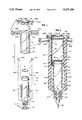
- FIG. 1is an exploded perspective view of a novel blood sampling syringe, constructed according to the teachings of the present invention
- FIG. 2is a sectioned elevational view of the syringe of FIG. 1 with the syringe being in an extended position;
- FIG. 3is a view, similar to that of FIG. 2, with the syringe in a collapsed position;
- FIG. 4is a sectioned elevational view of an alternative embodiment of the invention having means for providing enhanced tactile feel and for producing an auditory indication of negative pressure applied by the syringe.
- FIG. 1a novel sampling device or blood sampling syringe 10, constructed according to the teachings of the present invention, is shown in exploded perspective form. While the syringe 10 will be discussed with relation to its employment in drawing blood from a patient, it is envisioned that the syringe 10 can be successfully employed in drawing or sampling other fluids without departing from the scope of the invention.
- the syringe 10generally comprises four main elements: a main or first tube or sleeve member 12, and a secondary tube or sleeve member 14, a filter 16 and a cap member 18.
- the members 12, 14, and 18are preferably molded from a suitable plastic material, such as polypropylene or the like. By molding the members 12, 14 and 18 from plastic, the syringe 10 is relatively inexpensive, thereby rendering it economically disposable.
- the filter 16is preferably a substantially disk-shaped portion of hydrophobic filter media, such as that commonly known as PorexTM, the significance of which will become more apparent from the discussion to follow.
- the member 12generally comprises a substantially cylindrical tube 20 having an open upper end 22 and an enlarged base portion 24 on opposite axial ends thereof.
- Means for allowing blood flow into the member 12 in the form of a hypodermic needle mount 26, including threads 28 for threadibly accepting a hypodermic needle assembly 29,depends from the base portion 24.
- the base portion 24further includes a tapered bore 30 having a diameter which gradually decreases from a juncture of the bore 30 with a receiving chamber or interior 32 of the tube 20, as the bore 30 extends through the mount 26.
- bloodcan pass through the needle 29 and the bore 30 into the interior 32 of the tube 20.
- Bifurcated handle portions 34A and 34extend from the base portion 24 away from the mount 26 spaced from tube 20 and substantially parallel to an axis of elongation of the tube 20 along diametrically opposite sides thereof.
- the handle portions 34A and 34Bhave a length substantially longer than the axial length of the tube 20, and the portions 34A and 34B are radially offset from the outer cylindrical wall 36 of the tube 20 to define spaces 38, the significance of which will be discussed in detail hereinafter.
- the ends of the handle portions 34A and 34B opposite to the ends thereof defined by the base portion 24terminate in projecting tabs 40A and 40B, respectively, for forming a snap-fit between the member 12 and the cap member 18 to mount the cap member 18 to the upper ends of said handle portion, see FIG. 2.
- the plastic forming the member 12has sufficient elasticity to allow the tabs 40A and 40B to flex into engagement with mating structures on the cap 18, as will be discussed later.
- the tube 20also includes an annular recess or groove 42 proximate to the open end 22 for accepting sealing means in the form of an O-ring 44, preferably constructed from a suitable elastomeric material, such as rubber and the like.
- the O-ring 44forms a seal between the outer sleeve member 12 and the inner sleeve member 14, and permits a vacuum to be drawn upon relative movement between the sleeve or like members 12 and 14.
- the interior 32 of the tube 20is defined by a diameter somewhat smaller than a diameter of the filter 16. This allows the filter 16 to be press-fitted into the interior 32 at a location preferably between the recess 42 and the open end 22. The filter 16 extends across the entirety of the interior 32 at that location.
- the filter 16allows air to pass freely therethrough into and out of the interior 32, while preventing flow of blood or other bodily fluid therethrough and beyond the open end 22.
- blood drawn from a patientcan be positively retained within the interior 32 between the filter 16 and the mount 26.
- the structure of the inner sleeve member 14is also visible in FIGS. 1, 2 and 3.
- the sleeve member 14generally comprises a substantially cylindrical tube 46 having a closed end 48 and an open end 50 on opposite axial ends thereof. Finger grip portions 52A and 52B extend radially outwardly from the tube 46 proximate the closed end 48 which cooperate with the cap member 18 for facilitating operation of the syringe 10, as will be discussed further hereinafter.
- the tube 46also has an inner cylindrical wall surface 54 and an outer cylindrical wall surface 56.
- the inner wall surface 54is defined by a diameter slightly larger than a diameter defining the wall 36 of the tube 20, while the outer wall surface 56 is defined by a diameter slightly smaller than a diameter which defines the offset relationship of the handle portions 34A and 34B.
- the thickness of the tube 46is somewhat smaller than the width of the spaces 38 between handle portion 34A and 34B and the tube wall 20, thereby allowing the inner sleeve member 14 to be slidably disposed within the spaces 38 and about the tube 20 which is coaxially located within a receiving chamber or interior 58 of the tube 46, as illustrated in FIGS. 2 and 3.
- the interior 32 of the first tube 12communicates with the interior 58 of the second tube 14 across the filter 16.
- the finger portions 52A and 52Brespectively include apertures 60A and 60B for slidably accepting the handle portions 34A and 34B.
- the wall 36opposes the inner surface 54 while the outer surface 56 opposes the handle portions 34A and 34B.
- the inner surface 54is also in sliding engagement with the O-ring 44. Accordingly, the O-ring 44 forms an air-tight seal between the interior 32 and the interior 58.
- the open end 22 of the tube 20 and an annular portion 62act as positive stops for positively limiting relative axial shifting of the members 12 and 14 between a first or collapsed position, shown in FIG. 3, and a second or extended position of FIG. 2, as will be discussed in greater detail later.
- the cap member 18generally comprises a substantially circular disk portion 64 and a pair of radial projections 66A and 66B extending from the portion 64.
- the portion 64 and the projections 66A and 66Bare intended to be contacted by a technician's palm or thumb for facilitating relative axial shifting of the members 12 and 14.
- Apertures 68A and 68Bare disposed through the projections 66A and 66B and are configured and located for lockingly accepting the tabs 40A and 40B, respectively.
- the cap member 18further includes a positive stop portion 70 for limiting relative axial shifting of the members 12 and 14. To complete assembly of the syringe 10, after the member 14 is disposed within the space 38 as discussed hereinabove and as illustrated in FIGS.
- the cap member 18is snap-fitted onto the member 12 by pressing the tabs 40A and 40B through the apertures 68A and 68B. Once through the apertures 68A and 68B, the tabs 40A and 40B lock against a side of the projections 66A and 66B, respectively, opposite to the stop portion 70.
- FIG. 4A modified embodiment of the invention, syringe 72, is illustrated in FIG. 4.
- the syringe 72is substantially similar to the syringe 10, as is indicated by the like reference numerals, except for the differences to be noted hereinbelow.
- the syringe 72has rachet means 74 for providing a technician with enhanced tactile feel as well as an auditory indication of the reduced or negative pressure applied by the syringe 72 to the patient's vascular system.
- the rachet means 74is constructed to function equally well both during shifting the syringe 10 from the collapsed to the extended position and the reverse.
- the rachet means 74comprises a tooth-like projection 76 which extends laterally from the handle portion 34B, respectively, inwardly towards the wall 36 of the tube 20 at a predetermined location on the portion 34B.
- the projection 76cooperates with a substantially linear series of complimentary tooth-like projections 78 on the inner sleeve or tube member 14 which project outwardly away from the outer wall surface 56 and extend along a predetermined, effective axial length of that surface 56.
- the location of the projection 76 and the length of the series of projections 78 along the axis of elongation of the member 14are predetermined such that the projection 76 constantly engages the projection 78 as the members 12 and 14 are relatively axially shifted between the extended and the collapsed positions.
- the plastic materialprovides the projections 76 and 78 with sufficient flexibility for allowing the projections 76 and 78 to flex into and out of interengagement responsive to relative axial shifting of the members 12 and 14.
- an auditory signalis produced, indicative of the negative pressure applied to the patient.
- the rachet means 74provides the technician with an increased tactile feel responsive to the negative pressure.
- the syringe 10With the construction of the syringe 10 being disclosed in detail hereinabove, the operation thereof will now be discussed. Again, while the operation of the syringe 10 will be discussed with its employment in drawing blood from a patient, it is to be clearly understood that the syringe 10 can be effectively utilized in a number of different employments by different operators without departing from the scope of the invention. Also, because the methods of preparation of a patient for a blood draw, mounting of a needle on the needle mount 26, and properly inserting the needle into a patient's vascular system are well known in the relevant art, those methods will not be discussed herein. Accordingly, the operation of the syringe 10 will be discussed with an understanding that those methods have already been performed. Also, it is to be noted that the syringes 10 and 72 function substantially similarly.
- the syringe 10is in the collapsed or initial position, illustrated in FIG. 3 and is connected to a needle assembly 29 (not shown in FIG. 3).
- the needle assembly 29in turn is inserted into a patient's vascular system.
- the techniciangrasps the syringe 10 with one hand by placing either his thumb or palm in contact with the disk portion 64 of the cap member 18, and by simultaneously placing his fingers, preferably the pointer and the index fingers, in appropriate contact with the projections 52A and 52B on the member 14. By assuming this appropriate positioning, the technician is able to operate the syringe 10 with only one hand to produce relative movement between sections 12 and 14 to apply negative pressure to the needle assembly 29.
- the collapsed or initial positionis defined by the confrontation of the open end 22 of the member 12 with the closed end 48 of the member 14.
- the open end 50 of the member 14may confront the annular portion 62 of the base portion 24 of the member 12.
- the ends 22 and 48, and the end 50 and the portion 62can act as positive stop members for positively limiting relative axial shifting of the members 12 and 14.
- the interior 32 of the tube 20is filled with air, thereby preventing appreciable blood flow from the patient's vascular system into the syringe 10.
- the syringe 72 having rachet means 74is used, the disposition of the means 74 is predetermined so that the projections 76 and 78 are in interengagement. As the technician relatively axially shifts the members 12 and 14, the projections 76 and 78 will successively engage to provide audio and tactile feedback.
- the technicianTo draw blood from the patient, the technician flexes his fingers towards his palm or thumb. These finger movements cause the members 12 and 14 to relatively axially shift towards the extended or final position of FIG. 2. As this shifting occurs, the closed end 48 of the member 14 moves farther and farther away from the open end 22 of the member 12.
- the air within the interior 32 of the tube 20is drawn through the filter 16 and into the interior 58 of the tube 46.
- the seal provided by the O-ring 44insures that the air drawn into the interior 58 comes only from the interior 32 through the filter 16, and not form an ambient atmosphere.
- the volume of air drawn from the interior 32 into the interior 58is replaced by a corresponding volume of blood drawn from the patient.
- a negative pressureis generated within the interior 32, which is applied to the patient's vascular system through the needle assembly 29.
- the application of this negative pressurecauses blood to be drawn from the patient into the interior 32.
- the syringe 10is able to apply a controlled, variable negative pressure to the patient's vascular system.
- the application of negative pressurecan be as gentle as necessary. This is particularly important for patients who have weak blood vessels or vascular disease. Collapse of the patient's blood vessels during the blood draw can be eliminated by proper manipulation of the syringe 10 by the technician because the technician can directly regulate blood flow rate into the syringe 10.
- the technicianis provided with a greater tactile feel responsive to the degree of negative pressure applied to the patient and an auditory indication of that degree of negative pressure, thereby allowing the technician to more carefully monitor the rate of blood flow into the interior 32. Also, the syringe 10 is reversible, allowing the technician to account for unexpected problems that may arise during a blood draw.
- the techniciandraws more and more blood as the members 12 and 14 are axially shifted, separating the open end 22 of the tube 20 from the closed end 48 of the tube 46 by a progressively greater distance.
- the filter 16allows air within the interior 32 of the tube 20 to flow into the interior 58 of the tube 46.
- the hydrophobic nature of the filter 16prevents blood or other fluid located within the interior 32 from flowing therethrough and into the interior 58.
- the extended positionis defined by confrontation of the closed end 48 of the member 14 with the positive stop portion 70 on the cap member 18.
- the stop portion 70prevents the members 12 and 14 from being axially shifted beyond the extended position, thereby limiting the amount of blood that can be drawn into the interior 32.
- the techniciancan reverse the direction of blood flow into the interior 32 by appropriate force application to the finger portions 52A and 52B and the cap member 18, thereby reversing direction of axial shifting of the members 12 and 14. If blood flow reversal is desired, then the reversed axial shifting of the members 12 and 14 causes the volume of air disposed within the interior 58 to be forced back through the filter 16 and into the interior 32, thereby displacing blood in the interior 32. Resumption of blood draw can also occur at any time by inducing appropriate relative axial shifting of the members 12 and 14.
- the rachet means 74does not affect the ability of the members 12 and 14 to shift in either direction, and further provides increased tactile feel and auditory indications irrespective of shift direction, thereby allowing the technician to more precisely monitor and control the blood draw from the patient.
- the syringes 10 and 72 of the present invention hereintofore disclosedare significant improvements over the blood sampling devices of the prior art.
- the syringes 10 and 72allow for application of a controlled fluid-drawing negative pressure to a vascular system which is gentler than the negative pressures applied by some of the prior art devices.
- the syringes 10 and 72are one-handed operable, and can have means for providing an operator with enhanced tactile feel and an auditory indication of negative pressure applied by the syringe 72.
- the syringes 10 and 72comprise only five parts, viz. the members 12, 14, and 18, the filter 16 and the O-ring 44, and because these parts are composed of relatively inexpensive materials, the syringes 10 and 72 are relatively inexpensive, as compared to some of the devices of the prior art, and is economically disposable.
Landscapes
- Health & Medical Sciences (AREA)
- Life Sciences & Earth Sciences (AREA)
- Engineering & Computer Science (AREA)
- Animal Behavior & Ethology (AREA)
- Hematology (AREA)
- Veterinary Medicine (AREA)
- Public Health (AREA)
- Biomedical Technology (AREA)
- Heart & Thoracic Surgery (AREA)
- General Health & Medical Sciences (AREA)
- Pathology (AREA)
- Surgery (AREA)
- Molecular Biology (AREA)
- Medical Informatics (AREA)
- Biophysics (AREA)
- Physics & Mathematics (AREA)
- Manufacturing & Machinery (AREA)
- Vascular Medicine (AREA)
- Anesthesiology (AREA)
- Measurement Of The Respiration, Hearing Ability, Form, And Blood Characteristics Of Living Organisms (AREA)
- Infusion, Injection, And Reservoir Apparatuses (AREA)
Abstract
Description
The present invention generally relates to a novel sampling device for sampling blood, or the like. The invention more specifically relates to a novel blood sampling syringe for sampling or drawing blood from a patient which provides significant improvements over the blood sampling syringes of the prior art.
Many techniques and devices have been developed over the years for sampling blood and other bodily fluids from a patient. One such method is utilization of a standard hypodermic syringe. With this method, a hypodermic needle is attached to the syringe, with a piston of the syringe being in a collapsed position. The needle is then inserted through the skin and into a patient's blood vessel. To draw blood from the patient's vascular system, a technician must shift the piston into an extended position, thereby generating a negative pressure within the syringe which, when applied to the vascular system through the needle, draws blood into the syringe. The technician must be careful to shift the piston without removing the needle from the blood vessel while drawing blood in order to avoid injuring the patient.
While effective, this method presents some drawbacks which make it cumbersome to use. For example, to shift the syringe piston into the extended position, the technician often must grasp the syringe with two hands: one hand holding the main body of the syringe while the other shifts the piston.
In an effort to reduce these complications, other devices have been developed. One such device employs a substantially hollow housing upon which a hypodermic needle can be mounted, and a sealed pre-evacuated blood-receiving tube insertable into the housing for operative connection to the needle. In use, the needle is attached to the housing and is inserted into the patient's blood vessel. A portion of the needle extends through the housing and terminates in the hollow interior thereof. A pre-evacuated tube is inserted into the hollow interior such that the terminal end of the needle pierces the seal of the tube. Negative pressure present within the tube is applied through the needle to the patient's blood vessel, thereby drawing blood therefrom into the tube. When the tube is sufficiently full, the tube is removed from the hollow interior, thereby breaking the connection between the needle and the tube, and removing the negative pressure from the blood vessel.
While this device is effective, it also presents drawbacks in some instances which make it incompatible with some patients. Specifically, while the technician need not use both hands to draw blood into the tube, as opposed to the syringe method discussed hereinabove, use of both hands is required when inserting the pre-evacuated tube and removing the filled tube so that the needle will not be dislodged from the blood vessel.
Utilization of the pre-evacuated tube itself can present other problems. Because the tube has been pre-evacuated, the negative pressure applied to the patient is applied rapidly and is not regulated, and the technician lacks control of the rate of blood drawn from the patient's vascular system. For elderly or infant patients who may have delicate or fragile blood vessels, or those who suffer from a vascular disease, their blood vessels may collapse because of the application of unregulated negative pressure, resulting in serious harm to the patient. The pre-evacuated tube also prevents reversal of the blood draw, which may be necessary in some circumstances.
Another improvement in devices for sampling blood is disclosed in the patent to Downey, U.S. Pat. No. 4,813,433, viz. a different construction for a sampling syringe. This syringe generally comprises a hollow tube bifurcated diametrically along an axial length thereof by a partition wall to form two substantially half-cylindrical chambers. A semi- circular piston is shiftably disposed within one chamber which communicates with the other, to which a hypodermic needle is connected, through an aperture in the partition wall. In this manner, as the piston properly shifts within one chamber, a negative pressure is generated in the other chamber, thereby drawing blood into that chamber from the patient.
While this device is also effective, it too presents certain drawbacks. Because this device is also basically a syringe, it has the same two-handed operational requirements and limitations discussed in detail hereinabove. Furthermore, the bifurcated structure of the syringe is cumbersome and expensive to manufacture and difficult to mold from a plastic material. These manufacturing difficulties result in the syringe having an increased cost, thereby reducing the economic disposability thereof. In addition, it is relatively difficult to form and maintain a seal around the semicircular piston required with this design, which further increases the cost of the syringe, as well as making it more complicated to operate.
The novel blood sampling syringe of the present invention is intended to solve some, if not all, of the problems presented by the blood sampling methods and devices of the prior art discussed above. Specifically, the blood sampling syringe of the invention provides for one-handed, controlled negative pressure blood draw from a patient. This syringe allows a technician to gently apply negative pressure to a patient's vascular system. The technician can regulate negative pressure application while also being able to reverse the blood flow in the syringe, if necessary. This novel syringe comprises relatively few parts, is relatively easily and inexpensively molded and manufactured, and is therefore economically disposable.
A general object of the present invention is to provide a novel sampling device for blood or other fluids.
A more specific object of the invention is to provide a novel blood sampling syringe which allows for the controlled application of a blood-drawing negative pressure to a patient's vascular system which is gentler than the negative pressures applied by some of the blood sampling syringes of the prior art.
Another object of the present invention is to provide a novel blood sampling syringe that allows for one-handed operation thereof.
An additional object of the invention is to provide a novel blood sampling syringe which allows for controlled blood draw from a patient.
A further object of the present invention is to provide a novel blood sampling syringe which positively stops application of negative pressure to a patient's vascular system for preventing overdraw of blood therefrom.
Yet another object of the invention is to provide a novel blood sampling syringe which provides a technician with enhanced tactile feel and an auditory indication of negative pressure applied by the syringe.
A novel sampling syringe, for sampling blood or other bodily fluids from a patient, constructed according to the teaching of the present invention, comprises a first sleeve or tube member and a second sleeve or tube member disposed for relative shifting. The first sleeve member includes a first receiving chamber, and the second sleeve member includes a second receiving chamber. A needle mount is disposed on the first sleeve member for holding a needle in operative connection with the first receiving chamber so that bodily fluids can pass from the needle into the first receiving chamber. A filter is disposed in at least one of the first and the second sleeve members for permitting gas flow but prohibiting bodily fluid flow therethrough. The first receiving chamber communicates with the second receiving chamber through the filter so that relative shifting of the sleeve members causes gas within the first receiving chamber to flow through the filter into the second receiving chamber, thereby causing bodily fluid to flow into the first receiving chamber.
The organization and manner of the structure and operation of the invention, together with further objects and advantages thereof, may best be understood by reference to the following description taken in connection with the accompanying drawings, wherein like reference numerals identify like elements in which:
FIG. 1 is an exploded perspective view of a novel blood sampling syringe, constructed according to the teachings of the present invention;
FIG. 2 is a sectioned elevational view of the syringe of FIG. 1 with the syringe being in an extended position;
FIG. 3 is a view, similar to that of FIG. 2, with the syringe in a collapsed position; and
FIG. 4 is a sectioned elevational view of an alternative embodiment of the invention having means for providing enhanced tactile feel and for producing an auditory indication of negative pressure applied by the syringe.
While the invention may be susceptible to embodiment in different forms, there is shown in the drawings, and herein will be described in detail, specific embodiments with the understanding that the present disclosure is to be considered an exemplification of the principles of the invention, and is not intended to limit the invention to that as illustrated and described herein.
Referring initially to FIG. 1, a novel sampling device orblood sampling syringe 10, constructed according to the teachings of the present invention, is shown in exploded perspective form. While thesyringe 10 will be discussed with relation to its employment in drawing blood from a patient, it is envisioned that thesyringe 10 can be successfully employed in drawing or sampling other fluids without departing from the scope of the invention.
As illustrated in FIG. 1, thesyringe 10 generally comprises four main elements: a main or first tube orsleeve member 12, and a secondary tube orsleeve member 14, afilter 16 and acap member 18. Themembers members syringe 10 is relatively inexpensive, thereby rendering it economically disposable. Thefilter 16 is preferably a substantially disk-shaped portion of hydrophobic filter media, such as that commonly known as Porex™, the significance of which will become more apparent from the discussion to follow.
The structures of themembers member 12 generally comprises a substantiallycylindrical tube 20 having an openupper end 22 and anenlarged base portion 24 on opposite axial ends thereof. Means for allowing blood flow into themember 12 in the form of ahypodermic needle mount 26, includingthreads 28 for threadibly accepting ahypodermic needle assembly 29, depends from thebase portion 24. Thebase portion 24 further includes a taperedbore 30 having a diameter which gradually decreases from a juncture of thebore 30 with a receiving chamber orinterior 32 of thetube 20, as thebore 30 extends through themount 26. Thus, blood can pass through theneedle 29 and thebore 30 into the interior 32 of thetube 20.
Bifurcatedhandle portions 34A and 34 extend from thebase portion 24 away from themount 26 spaced fromtube 20 and substantially parallel to an axis of elongation of thetube 20 along diametrically opposite sides thereof. Thehandle portions tube 20, and theportions cylindrical wall 36 of thetube 20 to definespaces 38, the significance of which will be discussed in detail hereinafter.
The ends of thehandle portions base portion 24 terminate in projectingtabs member 12 and thecap member 18 to mount thecap member 18 to the upper ends of said handle portion, see FIG. 2. The plastic forming themember 12 has sufficient elasticity to allow thetabs cap 18, as will be discussed later.
Thetube 20 also includes an annular recess or groove 42 proximate to theopen end 22 for accepting sealing means in the form of an O-ring 44, preferably constructed from a suitable elastomeric material, such as rubber and the like. The O-ring 44 forms a seal between theouter sleeve member 12 and theinner sleeve member 14, and permits a vacuum to be drawn upon relative movement between the sleeve or likemembers tube 20 is defined by a diameter somewhat smaller than a diameter of thefilter 16. This allows thefilter 16 to be press-fitted into the interior 32 at a location preferably between therecess 42 and theopen end 22. Thefilter 16 extends across the entirety of the interior 32 at that location. Due to the hydrophobic nature of thefilter 16, thefilter 16 allows air to pass freely therethrough into and out of the interior 32, while preventing flow of blood or other bodily fluid therethrough and beyond theopen end 22. Thus, blood drawn from a patient can be positively retained within the interior 32 between thefilter 16 and themount 26.
The structure of theinner sleeve member 14 is also visible in FIGS. 1, 2 and 3. Thesleeve member 14 generally comprises a substantiallycylindrical tube 46 having aclosed end 48 and anopen end 50 on opposite axial ends thereof.Finger grip portions tube 46 proximate theclosed end 48 which cooperate with thecap member 18 for facilitating operation of thesyringe 10, as will be discussed further hereinafter. Thetube 46 also has an innercylindrical wall surface 54 and an outercylindrical wall surface 56. Theinner wall surface 54 is defined by a diameter slightly larger than a diameter defining thewall 36 of thetube 20, while theouter wall surface 56 is defined by a diameter slightly smaller than a diameter which defines the offset relationship of thehandle portions
Accordingly, the thickness of thetube 46 is somewhat smaller than the width of thespaces 38 betweenhandle portion tube wall 20, thereby allowing theinner sleeve member 14 to be slidably disposed within thespaces 38 and about thetube 20 which is coaxially located within a receiving chamber orinterior 58 of thetube 46, as illustrated in FIGS. 2 and 3. The interior 32 of thefirst tube 12 communicates with the interior 58 of thesecond tube 14 across thefilter 16.
To facilitate the above disposition, thefinger portions apertures handle portions members wall 36 opposes theinner surface 54 while theouter surface 56 opposes thehandle portions inner surface 54 is also in sliding engagement with the O-ring 44. Accordingly, the O-ring 44 forms an air-tight seal between the interior 32 and the interior 58. Theopen end 22 of thetube 20 and an annular portion 62 act as positive stops for positively limiting relative axial shifting of themembers
Thecap member 18 generally comprises a substantiallycircular disk portion 64 and a pair ofradial projections portion 64. Theportion 64 and theprojections members Apertures projections tabs cap member 18 further includes a positive stop portion 70 for limiting relative axial shifting of themembers syringe 10, after themember 14 is disposed within thespace 38 as discussed hereinabove and as illustrated in FIGS. 2 and 3, thecap member 18 is snap-fitted onto themember 12 by pressing thetabs apertures apertures tabs projections
A modified embodiment of the invention,syringe 72, is illustrated in FIG. 4. Thesyringe 72 is substantially similar to thesyringe 10, as is indicated by the like reference numerals, except for the differences to be noted hereinbelow. Specifically, thesyringe 72 has rachet means 74 for providing a technician with enhanced tactile feel as well as an auditory indication of the reduced or negative pressure applied by thesyringe 72 to the patient's vascular system. It is to be noted that the rachet means 74 is constructed to function equally well both during shifting thesyringe 10 from the collapsed to the extended position and the reverse.
In the illustrated embodiment, the rachet means 74 comprises a tooth-like projection 76 which extends laterally from thehandle portion 34B, respectively, inwardly towards thewall 36 of thetube 20 at a predetermined location on theportion 34B. Theprojection 76 cooperates with a substantially linear series of complimentary tooth-like projections 78 on the inner sleeve ortube member 14 which project outwardly away from theouter wall surface 56 and extend along a predetermined, effective axial length of thatsurface 56.
The location of theprojection 76 and the length of the series ofprojections 78 along the axis of elongation of themember 14 are predetermined such that theprojection 76 constantly engages theprojection 78 as themembers projections projections members projections
With the construction of thesyringe 10 being disclosed in detail hereinabove, the operation thereof will now be discussed. Again, while the operation of thesyringe 10 will be discussed with its employment in drawing blood from a patient, it is to be clearly understood that thesyringe 10 can be effectively utilized in a number of different employments by different operators without departing from the scope of the invention. Also, because the methods of preparation of a patient for a blood draw, mounting of a needle on theneedle mount 26, and properly inserting the needle into a patient's vascular system are well known in the relevant art, those methods will not be discussed herein. Accordingly, the operation of thesyringe 10 will be discussed with an understanding that those methods have already been performed. Also, it is to be noted that thesyringes
Thesyringe 10 is in the collapsed or initial position, illustrated in FIG. 3 and is connected to a needle assembly 29 (not shown in FIG. 3). Theneedle assembly 29 in turn is inserted into a patient's vascular system. The technician grasps thesyringe 10 with one hand by placing either his thumb or palm in contact with thedisk portion 64 of thecap member 18, and by simultaneously placing his fingers, preferably the pointer and the index fingers, in appropriate contact with theprojections member 14. By assuming this appropriate positioning, the technician is able to operate thesyringe 10 with only one hand to produce relative movement betweensections needle assembly 29.
As shown in FIG. 3, the collapsed or initial position is defined by the confrontation of theopen end 22 of themember 12 with theclosed end 48 of themember 14. Also, theopen end 50 of themember 14 may confront the annular portion 62 of thebase portion 24 of themember 12. In this way, the ends 22 and 48, and theend 50 and the portion 62 can act as positive stop members for positively limiting relative axial shifting of themembers interior 32 of thetube 20 is filled with air, thereby preventing appreciable blood flow from the patient's vascular system into thesyringe 10. If thesyringe 72 having rachet means 74 is used, the disposition of the means 74 is predetermined so that theprojections members projections
To draw blood from the patient, the technician flexes his fingers towards his palm or thumb. These finger movements cause themembers closed end 48 of themember 14 moves farther and farther away from theopen end 22 of themember 12. The air within theinterior 32 of thetube 20 is drawn through thefilter 16 and into the interior 58 of thetube 46. The seal provided by the O-ring 44 insures that the air drawn into the interior 58 comes only from the interior 32 through thefilter 16, and not form an ambient atmosphere. Thus, the volume of air drawn from the interior 32 into the interior 58 is replaced by a corresponding volume of blood drawn from the patient.
As themembers needle assembly 29. The application of this negative pressure causes blood to be drawn from the patient into the interior 32. Because the negative pressure is generated by the technician's hand movements, thesyringe 10 is able to apply a controlled, variable negative pressure to the patient's vascular system. Thus, the application of negative pressure can be as gentle as necessary. This is particularly important for patients who have weak blood vessels or vascular disease. Collapse of the patient's blood vessels during the blood draw can be eliminated by proper manipulation of thesyringe 10 by the technician because the technician can directly regulate blood flow rate into thesyringe 10. If thesyringe 72 having rachet means 74 is used, then the technician is provided with a greater tactile feel responsive to the degree of negative pressure applied to the patient and an auditory indication of that degree of negative pressure, thereby allowing the technician to more carefully monitor the rate of blood flow into the interior 32. Also, thesyringe 10 is reversible, allowing the technician to account for unexpected problems that may arise during a blood draw.
The technician draws more and more blood as themembers open end 22 of thetube 20 from theclosed end 48 of thetube 46 by a progressively greater distance. Thefilter 16 allows air within theinterior 32 of thetube 20 to flow into the interior 58 of thetube 46. However, the hydrophobic nature of thefilter 16 prevents blood or other fluid located within the interior 32 from flowing therethrough and into the interior 58. Furthermore, to prevent blood flow into the interior 58 and to prevent overdraw of blood from the patient, the extended position is defined by confrontation of theclosed end 48 of themember 14 with the positive stop portion 70 on thecap member 18. The stop portion 70 prevents themembers
At any time, the technician can reverse the direction of blood flow into the interior 32 by appropriate force application to thefinger portions cap member 18, thereby reversing direction of axial shifting of themembers members filter 16 and into the interior 32, thereby displacing blood in the interior 32. Resumption of blood draw can also occur at any time by inducing appropriate relative axial shifting of themembers members
Thesyringes syringes syringes syringe 72. Furthermore, because thesyringes members filter 16 and the O-ring 44, and because these parts are composed of relatively inexpensive materials, thesyringes
While preferred embodiments of the present invention are shown and described, it is envisioned that those skilled in the art may devise various modifications of the present invention without departing from the spirit and scope of the appended claims.
Claims (18)
1. A syringe for sampling bodily fluids, such as blood or the like, from a patient, said syringe comprising: a first sleeve member and a second sleeve member disposed for relative shifting; said first sleeve member including a first receiving chamber, and said second sleeve member including a second receiving chamber said first receiving chamber being relatively shiftably disposed within said second receiving chamber; sealing means being disposed between said first receiving chamber and said second receiving chamber for sealing engagement therebetween; means for mounting a needle associated with said first sleeve member for holding a needle in operative connection with said first receiving chamber so that bodily fluids can pass from a needle into said first receiving chamber; filter means disposed in at least one of said first and said second sleeve members for permitting gas flow but prohibiting bodily fluid flow therethrough; said first receiving chamber communicating with said second receiving chamber through said filter means; and proper relative shifting of said sleeve members causing gas within said first receiving chamber to flow through said filter means into said second receiving chamber, thereby causing bodily fluid to flow into said first receiving chamber.
2. A syringe as defined in claim 1, wherein the filter means comprises a piece of hydrophobic filter media.
3. A syringe as defined in claim 1, further comprising means operatively connected to the first sleeve member and the second sleeve member for facilitating one-handed relative shifting of said first sleeve member and said second sleeve member.
4. A syringe as defined in claim 3 wherein the means comprises a portion operatively connected to at least one of said first sleeve member and said second sleeve member for engagement with an operator's fingers and another portion connected to another of said first sleeve member and said second sleeve member for engagement with at least one of an operator's palm and thumb.
5. A syringe as defined in claim 1, further comprising means operatively associated with the first sleeve member and the second sleeve member for providing an operator with increased tactile feel and an auditory indication of bodily fluid flow in said first receiving chamber.
6. A syringe as defined in claim 5, wherein said means comprises interengaging projections extending from said first sleeve member and said second sleeve member.
7. A syringe as defined in claim 1, further comprising positive stop means on at least one of said first sleeve member and said second sleeve member for positively limiting relative shifting between the first position and the second position.
8. A syringe for sampling blood from a patient, the syringe comprising: an inner tube and an outer tube coaxially disposed for relative axial shifting; means operatively connected to the inner tube for allowing blood flow into said inner tube responsive to the axial shifting; hydrophobic filter means operatively connecting said inner tube to said outer tube for permitting gas flow and for prohibiting blood flow to and from said inner tube into and out of said outer tube responsive to said axial shifting; a reduced pressure generated in the inner tube by gas flow from said inner tube into said outer tube through said filter means; the reduced pressure causing blood to flow from said means for allowing blood flow into said inner tube; and manipulation means operatively connected to said inner tube and said outer tube for facilitating said axial shifting.
9. A syringe as defined in claim 8, wherein the inner tube has an open end, opposite to the means for allowing blood flow, which opens into the outer tube; the filter means comprising a piece of hydrophobic filter media filling said inner tube adjacent the open end; the outer tube comprising a closed end variably offset from the open end responsive to the axial shifting; and sealing means disposed between said inner tube and said outer tube for sealing engagement therebetween.
10. A syringe as defined in claim 9, further comprising positive stop means formed by engagement of the open end with the closed end for positively limiting the axial shifting.
11. A syringe as defined in claim 8, wherein the manipulation means comprises a base connected to said inner tube for engagement with at least one of an operator's thumb and palm, and a projection extending from said outer tube for engagement with an operator's finger.
12. A syringe as defined in claim 8, further comprising positive stop means for positively limiting the axial shifting.
13. A syringe as defined in claim 8, wherein the manipulation means comprises a bifurcated handle extending axially along said inner tube, and a projection substantially radially extending from the outer tube; a space defined by the handle and the inner tube of dimensions sufficient for accepting the outer tube; the outer tube being shiftably disposed within said space; and positive stop means further defining said space for positively limiting said axial shifting.
14. A syringe as defined in claim 8, further comprising means operatively associated with the inner tube and the outer tube for providing an operator with increased tactile feel and an auditory indication of blood flow in said inner tube.
15. A syringe as defined in claim 14, wherein said means for providing increased tactile feel comprises interengaging projections extending from said inner tube and said outer tube.
16. A device for sampling fluids comprising: a first tube and a second tube coaxially disposed for relative axial shifting; means operatively connected to the first tube for allowing fluid flow into said first tube; filter means operatively connecting said first tube with said second tube for allowing gas flow and for prohibiting fluid flow from said first tube into said second tube responsive to relative axial shifting of said first tube and said second tube; said relative axial shifting generating a reduced pressure within said first tube by drawing gas through the filter means from said first tube into said second tube; and the reduced pressure drawing fluid into said first tube.
17. A device as defined in claim 16, further comprising manipulation means connected to the first tube and the second tube for allowing relative axial shifting.
18. A device as defined in claim 16, further comprising means connected to the first tube and the second tube for providing increased tactile feel and an auditory indication of the reduced pressure drawing fluid into said first tube.
Priority Applications (1)
| Application Number | Priority Date | Filing Date | Title |
|---|---|---|---|
| US07/920,036US5277198A (en) | 1992-07-27 | 1992-07-27 | Blood sampling syringe |
Applications Claiming Priority (1)
| Application Number | Priority Date | Filing Date | Title |
|---|---|---|---|
| US07/920,036US5277198A (en) | 1992-07-27 | 1992-07-27 | Blood sampling syringe |
Publications (1)
| Publication Number | Publication Date |
|---|---|
| US5277198Atrue US5277198A (en) | 1994-01-11 |
Family
ID=25443051
Family Applications (1)
| Application Number | Title | Priority Date | Filing Date |
|---|---|---|---|
| US07/920,036Expired - Fee RelatedUS5277198A (en) | 1992-07-27 | 1992-07-27 | Blood sampling syringe |
Country Status (1)
| Country | Link |
|---|---|
| US (1) | US5277198A (en) |
Cited By (41)
| Publication number | Priority date | Publication date | Assignee | Title |
|---|---|---|---|---|
| US5857983A (en)* | 1996-05-17 | 1999-01-12 | Mercury Diagnostics, Inc. | Methods and apparatus for sampling body fluid |
| US5879311A (en)* | 1996-05-17 | 1999-03-09 | Mercury Diagnostics, Inc. | Body fluid sampling device and methods of use |
| EP0857460A3 (en)* | 1997-02-10 | 1999-03-17 | In-X Corporation | Arterial blood gas syringe including filter member |
| US5951492A (en)* | 1996-05-17 | 1999-09-14 | Mercury Diagnostics, Inc. | Methods and apparatus for sampling and analyzing body fluid |
| US5951493A (en)* | 1997-05-16 | 1999-09-14 | Mercury Diagnostics, Inc. | Methods and apparatus for expressing body fluid from an incision |
| US5964718A (en)* | 1997-11-21 | 1999-10-12 | Mercury Diagnostics, Inc. | Body fluid sampling device |
| US6015392A (en)* | 1996-05-17 | 2000-01-18 | Mercury Diagnostics, Inc. | Apparatus for sampling body fluid |
| US6048352A (en)* | 1996-05-17 | 2000-04-11 | Mercury Diagnostics, Inc. | Disposable element for use in a body fluid sampling device |
| US6162639A (en)* | 1997-12-19 | 2000-12-19 | Amira Medical | Embossed test strip system |
| US6203503B1 (en)* | 1997-09-12 | 2001-03-20 | Becton Dickinson And Company | Collection container assembly |
| US6332871B1 (en) | 1996-05-17 | 2001-12-25 | Amira Medical | Blood and interstitial fluid sampling device |
| US20020052050A1 (en)* | 1997-06-17 | 2002-05-02 | Douglas Joel S. | Device for determination of an analyte a in body fluid |
| US20020188223A1 (en)* | 2001-06-08 | 2002-12-12 | Edward Perez | Devices and methods for the expression of bodily fluids from an incision |
| US20030060730A1 (en)* | 2001-08-29 | 2003-03-27 | Edward Perez | Wicking methods and structures for use in sampling bodily fluids |
| US20040006285A1 (en)* | 1996-05-17 | 2004-01-08 | Douglas Joel S. | Methods and apparatus for sampling and analyzing body fluid |
| US6706000B2 (en) | 1997-11-21 | 2004-03-16 | Amira Medical | Methods and apparatus for expressing body fluid from an incision |
| US20040162506A1 (en)* | 1996-05-17 | 2004-08-19 | Duchon Brent G. | Body fluid sampling device and methods of use |
| US20040229347A1 (en)* | 2001-09-17 | 2004-11-18 | Perez Edward P. | Embossed test strip system |
| US20050010134A1 (en)* | 1996-05-17 | 2005-01-13 | Douglas Joel S. | Blood and interstitial fluid sampling device |
| US20050288605A1 (en)* | 2002-11-18 | 2005-12-29 | Pellegrino Richard C | Bone marrow aspiration system |
| GB2426293A (en)* | 2005-05-19 | 2006-11-22 | Bosch Gmbh Robert | Dispensing device |
| US20070093728A1 (en)* | 1996-05-17 | 2007-04-26 | Douglas Joel S | Blood and interstitial fluid sampling device |
| US20070112309A1 (en)* | 2005-11-17 | 2007-05-17 | Jerry Zucker | Withdrawal syringe |
| US20080149524A1 (en)* | 2003-03-27 | 2008-06-26 | Rademaker William B | Food containers including dental cleaning devices and other personal care items |
| US7758516B2 (en) | 2001-09-26 | 2010-07-20 | Roche Diagnostics Operations, Inc. | Method and apparatus for sampling bodily fluid |
| US7841991B2 (en) | 1996-05-17 | 2010-11-30 | Roche Diagnostics Operations, Inc. | Methods and apparatus for expressing body fluid from an incision |
| GB2506709A (en)* | 2012-10-04 | 2014-04-09 | Owen Mumford Ltd | Injector apparatus comprising two slidably connected conduits |
| WO2014145935A1 (en) | 2013-03-15 | 2014-09-18 | Theranos, Inc. | Systems, devices, and methods for bodily fluid sample collection |
| US9357950B2 (en) | 2009-06-03 | 2016-06-07 | Biometrix Ltd. | Apparatus and method of fluid aspiration |
| US9636062B2 (en) | 2012-09-06 | 2017-05-02 | Theranos, Inc. | Systems, devices, and methods for bodily fluid sample collection |
| WO2017129735A1 (en)* | 2016-01-28 | 2017-08-03 | Totle Development Aps | Biopsy syringe |
| US9877674B2 (en) | 2012-09-06 | 2018-01-30 | Theranos Ip Company, Llc | Systems, devices, and methods for bodily fluid sample collection |
| US9908113B2 (en) | 2013-03-15 | 2018-03-06 | Theranos Ip Company, Llc | Methods and devices for sample collection and sample separation |
| CN109199406A (en)* | 2018-07-13 | 2019-01-15 | 北京大学第医院 | A kind of adjustable vacuum blood collection tube of negative pressure |
| US10244973B2 (en) | 2012-12-05 | 2019-04-02 | Theranos Ip Company, Llc | Systems, devices, and methods for bodily fluid sample transport |
| US10248765B1 (en) | 2012-12-05 | 2019-04-02 | Theranos Ip Company, Llc | Systems, devices, and methods for bodily fluid sample collection, transport, and handling |
| US10371606B2 (en) | 2015-07-21 | 2019-08-06 | Theraos IP Company, LLC | Bodily fluid sample collection and transport |
| US10856791B2 (en) | 2014-03-12 | 2020-12-08 | Labrador Diagnostics Llc | Systems, devices, and methods for bodily fluid sample collection |
| US11007527B2 (en) | 2015-09-09 | 2021-05-18 | Labrador Diagnostics Llc | Devices for sample collection and sample separation |
| CN116584936A (en)* | 2023-07-17 | 2023-08-15 | 莱州市文昌路畜牧兽医站 | Blood station movable blood sampling storage device and use method |
| US11857966B1 (en) | 2017-03-15 | 2024-01-02 | Labrador Diagnostics Llc | Methods and devices for sample collection and sample separation |
Citations (5)
| Publication number | Priority date | Publication date | Assignee | Title |
|---|---|---|---|---|
| US3835835A (en)* | 1972-11-07 | 1974-09-17 | Richardson Merrell Inc | Two compartment locking sampling syringe |
| US3890956A (en)* | 1974-06-27 | 1975-06-24 | Deseret Pharma | Blood-gas sampler |
| US3960139A (en)* | 1975-01-15 | 1976-06-01 | Bailey Donald L | Syringe device with means for removing contaminates when drawing blood sample |
| US4373535A (en)* | 1981-08-17 | 1983-02-15 | Martell Michael D | Venting, self-stopping, aspirating syringe |
| US4813433A (en)* | 1988-04-11 | 1989-03-21 | Downey John M | Syringe for withdrawing blood |
- 1992
- 1992-07-27USUS07/920,036patent/US5277198A/ennot_activeExpired - Fee Related
Patent Citations (5)
| Publication number | Priority date | Publication date | Assignee | Title |
|---|---|---|---|---|
| US3835835A (en)* | 1972-11-07 | 1974-09-17 | Richardson Merrell Inc | Two compartment locking sampling syringe |
| US3890956A (en)* | 1974-06-27 | 1975-06-24 | Deseret Pharma | Blood-gas sampler |
| US3960139A (en)* | 1975-01-15 | 1976-06-01 | Bailey Donald L | Syringe device with means for removing contaminates when drawing blood sample |
| US4373535A (en)* | 1981-08-17 | 1983-02-15 | Martell Michael D | Venting, self-stopping, aspirating syringe |
| US4813433A (en)* | 1988-04-11 | 1989-03-21 | Downey John M | Syringe for withdrawing blood |
Cited By (85)
| Publication number | Priority date | Publication date | Assignee | Title |
|---|---|---|---|---|
| US5857983A (en)* | 1996-05-17 | 1999-01-12 | Mercury Diagnostics, Inc. | Methods and apparatus for sampling body fluid |
| US20050010134A1 (en)* | 1996-05-17 | 2005-01-13 | Douglas Joel S. | Blood and interstitial fluid sampling device |
| US8123701B2 (en) | 1996-05-17 | 2012-02-28 | Roche Diagnostics Operations, Inc. | Methods and apparatus for sampling and analyzing body fluid |
| US5951492A (en)* | 1996-05-17 | 1999-09-14 | Mercury Diagnostics, Inc. | Methods and apparatus for sampling and analyzing body fluid |
| US7901363B2 (en) | 1996-05-17 | 2011-03-08 | Roche Diagnostics Operations, Inc. | Body fluid sampling device and methods of use |
| US20110046515A1 (en)* | 1996-05-17 | 2011-02-24 | Douglas Joel S | Methods and apparatus for expressing body fluid from an incision |
| US6015392A (en)* | 1996-05-17 | 2000-01-18 | Mercury Diagnostics, Inc. | Apparatus for sampling body fluid |
| US6048352A (en)* | 1996-05-17 | 2000-04-11 | Mercury Diagnostics, Inc. | Disposable element for use in a body fluid sampling device |
| US7841991B2 (en) | 1996-05-17 | 2010-11-30 | Roche Diagnostics Operations, Inc. | Methods and apparatus for expressing body fluid from an incision |
| US7828749B2 (en) | 1996-05-17 | 2010-11-09 | Roche Diagnostics Operations, Inc. | Blood and interstitial fluid sampling device |
| US6099484A (en)* | 1996-05-17 | 2000-08-08 | Amira Medical | Methods and apparatus for sampling and analyzing body fluid |
| US20100222704A1 (en)* | 1996-05-17 | 2010-09-02 | Roche Diagnostics Operations, Inc. | Methods and apparatus for sampling and analyzing body fluid |
| US6183489B1 (en) | 1996-05-17 | 2001-02-06 | Amira Medical | Disposable element for use in a body fluid sampling device |
| US20100222656A1 (en)* | 1996-05-17 | 2010-09-02 | Roche Diagnostics Operations, Inc. | Methods and apparatus for sampling and analyzing body fluid |
| US6319210B1 (en) | 1996-05-17 | 2001-11-20 | Amira Medical | Methods and apparatus for expressing body fluid from an incision |
| US6332871B1 (en) | 1996-05-17 | 2001-12-25 | Amira Medical | Blood and interstitial fluid sampling device |
| US7731668B2 (en) | 1996-05-17 | 2010-06-08 | Roche Diagnostics Operations, Inc. | Methods and apparatus for sampling and analyzing body fluid |
| US7727168B2 (en) | 1996-05-17 | 2010-06-01 | Roche Diagnostics Operations, Inc. | Methods and apparatus for sampling and analyzing body fluid |
| US20100106058A1 (en)* | 1996-05-17 | 2010-04-29 | Douglas Joel S | Blood and interstitial fluid sampling device |
| US7666150B2 (en) | 1996-05-17 | 2010-02-23 | Roche Diagnostics Operations, Inc. | Blood and interstitial fluid sampling device |
| US8231549B2 (en) | 1996-05-17 | 2012-07-31 | Roche Diagnostics Operations, Inc. | Methods and apparatus for sampling and analyzing body fluid |
| US20040006285A1 (en)* | 1996-05-17 | 2004-01-08 | Douglas Joel S. | Methods and apparatus for sampling and analyzing body fluid |
| US8690798B2 (en) | 1996-05-17 | 2014-04-08 | Roche Diagnostics Operations, Inc. | Methods and apparatus for sampling and analyzing body fluid |
| US20040162506A1 (en)* | 1996-05-17 | 2004-08-19 | Duchon Brent G. | Body fluid sampling device and methods of use |
| US20080015425A1 (en)* | 1996-05-17 | 2008-01-17 | Roche Diagnostics Operations, Inc. | Methods and apparatus for sampling and analyzing body fluid |
| US6793633B2 (en) | 1996-05-17 | 2004-09-21 | Roche Diagnostics Operations, Inc. | Blood and interstitial fluid sampling device |
| US20070293747A1 (en)* | 1996-05-17 | 2007-12-20 | Roche Diagnostics Operations, Inc. | Methods and apparatus for sampling and analyzing body fluid |
| US7247144B2 (en) | 1996-05-17 | 2007-07-24 | Roche Diagnostics Operations, Inc. | Methods and apparatus for sampling and analyzing body fluid |
| US5879311A (en)* | 1996-05-17 | 1999-03-09 | Mercury Diagnostics, Inc. | Body fluid sampling device and methods of use |
| US7235056B2 (en) | 1996-05-17 | 2007-06-26 | Amira Medical | Body fluid sampling device and methods of use |
| US8696596B2 (en) | 1996-05-17 | 2014-04-15 | Roche Diagnostics Operations, Inc. | Blood and interstitial fluid sampling device |
| US20070093728A1 (en)* | 1996-05-17 | 2007-04-26 | Douglas Joel S | Blood and interstitial fluid sampling device |
| US8740813B2 (en) | 1996-05-17 | 2014-06-03 | Roche Diagnostics Operations, Inc. | Methods and apparatus for expressing body fluid from an incision |
| EP0857460A3 (en)* | 1997-02-10 | 1999-03-17 | In-X Corporation | Arterial blood gas syringe including filter member |
| US5951493A (en)* | 1997-05-16 | 1999-09-14 | Mercury Diagnostics, Inc. | Methods and apparatus for expressing body fluid from an incision |
| US6071250A (en)* | 1997-05-16 | 2000-06-06 | Amira Medical | Methods and apparatus for expressing body fluid from an incision |
| US6780651B2 (en) | 1997-06-17 | 2004-08-24 | Roche Diagnostics Operations, Inc. | Device for determination of an analyte in a body fluid |
| US20020052050A1 (en)* | 1997-06-17 | 2002-05-02 | Douglas Joel S. | Device for determination of an analyte a in body fluid |
| US6203503B1 (en)* | 1997-09-12 | 2001-03-20 | Becton Dickinson And Company | Collection container assembly |
| US6066103A (en)* | 1997-11-21 | 2000-05-23 | Amira Medical | Body fluid sampling device |
| US20040204662A1 (en)* | 1997-11-21 | 2004-10-14 | Perez Edward P. | Methods and apparatus for expressing body fluid from an incision |
| US6706000B2 (en) | 1997-11-21 | 2004-03-16 | Amira Medical | Methods and apparatus for expressing body fluid from an incision |
| US5964718A (en)* | 1997-11-21 | 1999-10-12 | Mercury Diagnostics, Inc. | Body fluid sampling device |
| US6464649B1 (en) | 1997-11-21 | 2002-10-15 | Amira Medical | Body fluid sampling device |
| US6969359B2 (en) | 1997-11-21 | 2005-11-29 | Roche Diagnostics Operations, Inc. | Body fluid sampling device |
| US6162639A (en)* | 1997-12-19 | 2000-12-19 | Amira Medical | Embossed test strip system |
| US6455324B1 (en) | 1997-12-19 | 2002-09-24 | Amira Medical | Embossed test strip system |
| US7758518B2 (en) | 2001-06-08 | 2010-07-20 | Roche Diagnostics Operations, Inc. | Devices and methods for expression of bodily fluids from an incision |
| US20020188223A1 (en)* | 2001-06-08 | 2002-12-12 | Edward Perez | Devices and methods for the expression of bodily fluids from an incision |
| US9538941B2 (en) | 2001-06-08 | 2017-01-10 | Roche Diabetes Care, Inc. | Devices and methods for expression of bodily fluids from an incision |
| US20090118752A1 (en)* | 2001-06-08 | 2009-05-07 | Edward Perez | Devices and methods for expression of bodily fluids from an incision |
| US20030060730A1 (en)* | 2001-08-29 | 2003-03-27 | Edward Perez | Wicking methods and structures for use in sampling bodily fluids |
| US7264627B2 (en) | 2001-08-29 | 2007-09-04 | Roche Diagnostics Operations, Inc. | Wicking methods and structures for use in sampling bodily fluids |
| US20040229347A1 (en)* | 2001-09-17 | 2004-11-18 | Perez Edward P. | Embossed test strip system |
| US7758516B2 (en) | 2001-09-26 | 2010-07-20 | Roche Diagnostics Operations, Inc. | Method and apparatus for sampling bodily fluid |
| US20050288605A1 (en)* | 2002-11-18 | 2005-12-29 | Pellegrino Richard C | Bone marrow aspiration system |
| US20080149524A1 (en)* | 2003-03-27 | 2008-06-26 | Rademaker William B | Food containers including dental cleaning devices and other personal care items |
| GB2426293B (en)* | 2005-05-19 | 2008-12-24 | Bosch Gmbh Robert | Dispensing device and method of operation thereof |
| US8235953B2 (en) | 2005-05-19 | 2012-08-07 | Robert Bosch Gmbh | Metering device and method for operating same |
| US8728986B2 (en) | 2005-05-19 | 2014-05-20 | Robert Bosch Gmbh | Metering device and method for operating same |
| US20060264817A1 (en)* | 2005-05-19 | 2006-11-23 | Thomas Brinz | Metering device and method for operating same |
| GB2426293A (en)* | 2005-05-19 | 2006-11-22 | Bosch Gmbh Robert | Dispensing device |
| WO2007059381A3 (en)* | 2005-11-17 | 2008-07-31 | Jerry Zucker | Withdrawal syringe |
| US20070112309A1 (en)* | 2005-11-17 | 2007-05-17 | Jerry Zucker | Withdrawal syringe |
| US9357950B2 (en) | 2009-06-03 | 2016-06-07 | Biometrix Ltd. | Apparatus and method of fluid aspiration |
| US10842424B2 (en) | 2012-09-06 | 2020-11-24 | Labrador Diagnostics Llc | Systems, devices, and methods for bodily fluid sample collection |
| US9877674B2 (en) | 2012-09-06 | 2018-01-30 | Theranos Ip Company, Llc | Systems, devices, and methods for bodily fluid sample collection |
| US9636062B2 (en) | 2012-09-06 | 2017-05-02 | Theranos, Inc. | Systems, devices, and methods for bodily fluid sample collection |
| GB2506709A (en)* | 2012-10-04 | 2014-04-09 | Owen Mumford Ltd | Injector apparatus comprising two slidably connected conduits |
| US10248765B1 (en) | 2012-12-05 | 2019-04-02 | Theranos Ip Company, Llc | Systems, devices, and methods for bodily fluid sample collection, transport, and handling |
| US10244973B2 (en) | 2012-12-05 | 2019-04-02 | Theranos Ip Company, Llc | Systems, devices, and methods for bodily fluid sample transport |
| WO2014145935A1 (en) | 2013-03-15 | 2014-09-18 | Theranos, Inc. | Systems, devices, and methods for bodily fluid sample collection |
| US9908113B2 (en) | 2013-03-15 | 2018-03-06 | Theranos Ip Company, Llc | Methods and devices for sample collection and sample separation |
| EP2968059A4 (en)* | 2013-03-15 | 2017-01-04 | Theranos, Inc. | Systems, devices, and methods for bodily fluid sample collection |
| US10856791B2 (en) | 2014-03-12 | 2020-12-08 | Labrador Diagnostics Llc | Systems, devices, and methods for bodily fluid sample collection |
| US10371606B2 (en) | 2015-07-21 | 2019-08-06 | Theraos IP Company, LLC | Bodily fluid sample collection and transport |
| US11305275B2 (en) | 2015-07-21 | 2022-04-19 | Labrador Diagnostics Llc | Bodily fluid sample collection and transport |
| US11007527B2 (en) | 2015-09-09 | 2021-05-18 | Labrador Diagnostics Llc | Devices for sample collection and sample separation |
| US11247208B2 (en) | 2015-09-09 | 2022-02-15 | Labrador Diagnostics Llc | Methods and devices for sample collection and sample separation |
| WO2017129735A1 (en)* | 2016-01-28 | 2017-08-03 | Totle Development Aps | Biopsy syringe |
| US11399813B2 (en) | 2016-01-28 | 2022-08-02 | Totle Development Aps | Biopsy syringe |
| US11857966B1 (en) | 2017-03-15 | 2024-01-02 | Labrador Diagnostics Llc | Methods and devices for sample collection and sample separation |
| CN109199406A (en)* | 2018-07-13 | 2019-01-15 | 北京大学第医院 | A kind of adjustable vacuum blood collection tube of negative pressure |
| CN116584936A (en)* | 2023-07-17 | 2023-08-15 | 莱州市文昌路畜牧兽医站 | Blood station movable blood sampling storage device and use method |
| CN116584936B (en)* | 2023-07-17 | 2023-12-15 | 莱州市文昌路畜牧兽医站 | Blood station movable blood sampling storage device and use method |
Similar Documents
| Publication | Publication Date | Title |
|---|---|---|
| US5277198A (en) | Blood sampling syringe | |
| US6159164A (en) | Blood sampling system | |
| US6860872B2 (en) | Safety syringe/catheter | |
| EP0279956B1 (en) | Aspiration syringe | |
| US10406328B2 (en) | Needle for bloodless IV | |
| US4043336A (en) | Sterile syringe device | |
| CN100589848C (en) | Suction regulating valve for operation | |
| JPS5810064A (en) | Blood sampling syringe | |
| US5554127A (en) | Syringe needle thimble cap and method of use thereof | |
| US4091812A (en) | Operator means for syringe cartridges | |
| US5374401A (en) | Blood sampling apparatus | |
| US3329391A (en) | Surgical pinch valve | |
| US7399292B2 (en) | Activation of dual blunting needle assembly | |
| EP3886935A1 (en) | Syringe accessory device and methods of use | |
| EP1554979A1 (en) | Dual blunting needle assembly | |
| JPH05168702A (en) | Fluid specimen sampling device | |
| IE912686A1 (en) | Assembly for aspirating tissue, including adapter for¹syringe | |
| CA1254094A (en) | Fluid sampling device | |
| KR910000191A (en) | Syringe assembly | |
| JP2000116768A (en) | Puncture appliance | |
| WO2001030415A2 (en) | Syringe | |
| US5921964A (en) | Safety blood collecting device | |
| WO2007059381A2 (en) | Withdrawal syringe | |
| WO1992014497A1 (en) | Improved aspirating device | |
| CA2154235C (en) | Syringe plunger with intermediate pushing surface |
Legal Events
| Date | Code | Title | Description |
|---|---|---|---|
| AS | Assignment | Owner name:RYDER INTERNATIONAL CORPORATION, A CORP. OF DE, AL Free format text:ASSIGNMENT OF ASSIGNORS INTEREST.;ASSIGNORS:KANNER, ROWLAND W.;RYDER, FRANCIS E.;REEL/FRAME:006241/0589 Effective date:19920717 | |
| FEPP | Fee payment procedure | Free format text:PAYOR NUMBER ASSIGNED (ORIGINAL EVENT CODE: ASPN); ENTITY STATUS OF PATENT OWNER: SMALL ENTITY | |
| AS | Assignment | Owner name:ATRION MEDICAL PRODUCTS, INC., ALABAMA Free format text:MERGER;ASSIGNOR:RYDER INTERNATIONAL CORPORATION;REEL/FRAME:008519/0569 Effective date:19961211 | |
| FPAY | Fee payment | Year of fee payment:4 | |
| FPAY | Fee payment | Year of fee payment:8 | |
| REMI | Maintenance fee reminder mailed | ||
| LAPS | Lapse for failure to pay maintenance fees | ||
| STCH | Information on status: patent discontinuation | Free format text:PATENT EXPIRED DUE TO NONPAYMENT OF MAINTENANCE FEES UNDER 37 CFR 1.362 | |
| FP | Lapsed due to failure to pay maintenance fee | Effective date:20060111 |