US5275557A - Self-locking orthodontic bracket - Google Patents
Self-locking orthodontic bracketDownload PDFInfo
- Publication number
- US5275557A US5275557AUS08/045,529US4552993AUS5275557AUS 5275557 AUS5275557 AUS 5275557AUS 4552993 AUS4552993 AUS 4552993AUS 5275557 AUS5275557 AUS 5275557A
- Authority
- US
- United States
- Prior art keywords
- archwire
- slot
- bracket
- cover
- tying
- Prior art date
- Legal status (The legal status is an assumption and is not a legal conclusion. Google has not performed a legal analysis and makes no representation as to the accuracy of the status listed.)
- Expired - Lifetime
Links
Images


Classifications
- A—HUMAN NECESSITIES
- A61—MEDICAL OR VETERINARY SCIENCE; HYGIENE
- A61C—DENTISTRY; APPARATUS OR METHODS FOR ORAL OR DENTAL HYGIENE
- A61C7/00—Orthodontics, i.e. obtaining or maintaining the desired position of teeth, e.g. by straightening, evening, regulating, separating, or by correcting malocclusions
- A61C7/12—Brackets; Arch wires; Combinations thereof; Accessories therefor
- A61C7/14—Brackets; Fixing brackets to teeth
- A61C7/146—Positioning or placement of brackets; Tools therefor
- A—HUMAN NECESSITIES
- A61—MEDICAL OR VETERINARY SCIENCE; HYGIENE
- A61C—DENTISTRY; APPARATUS OR METHODS FOR ORAL OR DENTAL HYGIENE
- A61C7/00—Orthodontics, i.e. obtaining or maintaining the desired position of teeth, e.g. by straightening, evening, regulating, separating, or by correcting malocclusions
- A61C7/12—Brackets; Arch wires; Combinations thereof; Accessories therefor
- A61C7/28—Securing arch wire to bracket
- A61C7/287—Sliding locks
- A—HUMAN NECESSITIES
- A61—MEDICAL OR VETERINARY SCIENCE; HYGIENE
- A61C—DENTISTRY; APPARATUS OR METHODS FOR ORAL OR DENTAL HYGIENE
- A61C2201/00—Material properties
- A61C2201/002—Material properties using colour effect, e.g. for identification purposes
Definitions
- This disclosurepertains to self-locking or ligatureless orthodontic brackets.
- Orthodontic brackets attached to teethare adapted to engage an archwire that exerts forces upon them to move the teeth.
- Such bracketstypically include an archwire slot for reception of the archwire.
- An archwire slotcan have any desired cross-sectional configuration or size to match requirements of the archwire, or archwires, that are to be engaged within the slot.
- Orthodontic bracketsare typically bonded to a tooth or to a tooth band with the archwire slot oriented parallel to the occlusal plane. However, the slot can also be angularly oriented across the bracket when desired.
- brackets in use todayinclude extensions that project upwardly and downwardly at the top and bottom of the installed bracket, respectively. These extensions permit the archwire to be held within the archwire slot of the bracket by means of a twisted wire (ligature) or an elastomer O-ring.
- ligaturetwisted wire
- O-ringelastomer
- an ideal locking device for an orthodontic bracketshould leave the top and bottom of the bracket, including the projections conventionally used for anchoring the tying wires, free to receive other attachments or auxiliary devices.
- the Wildman patentdiscloses a slidable closure that engages the front of the archwire.
- the closureis recessed from the front or anterior surfaces of the disclosed bracket.
- Thisis also true of sliding closures shown in U.S. Pat. No. 2,671,964 to Russell et al., which was issued on Mar. 16, 1954 and in U.S. Pat. No. 3,131,474, which was issued on May 5, 1964 to Johnson.
- the fact that such recessed sliding closuresrequire the archwire also to be recessed within the archwire slot before the closure can be moved over the archwire makes it very difficult for the user to visually confirm that the archwire is properly seated within the archwire slot to facilitate closing of the slidable cover.
- a flush-mounted closure in the form of a spring clipis shown in various embodiments illustrated within U.S. Pat. No. 4,023,274 to Wallshein, issued on May 17, 1977.
- FIGS. 4A and 4B of the Wallshein patentthere is illustrated a spring clip having a closure panel that extends across the full width of a bracket and covers aligned slots in two separate lugs.
- the spring clipalso covers the bottom of the bracket and presents a separable bracket element that must be attached to the bracket prior to its utilization.
- a sliding closureis more easily manipulated than a spring clip. Slidable closures are particularly desirable because they substantially reduce the time required for opening and closing of the archwire slots during periodic adjustment of the archwire and brackets.
- the present bracketwas designed to mount an archwire flush with the anterior surface of an orthodontic bracket to facilitate visual positioning of the archwire during orthodontic treatment. It also was designed to utilize a sliding closure that is permanently retained on the bracket during use, whether the closure is left in an open or closed condition. This guards against accidental release of the closure while the bracket is worn on a tooth.
- closurehas been designed to leave the usual tying extensions that protrude from the top and bottom of the bracket fully accessible to other orthodontic attachments to apply torsional forces to the teeth.
- the exposed tying lugsremain always available for repositioning of the bracket and tooth by use of tying wires or other conventional attachment systems.
- the present bracketalso includes a closure that completes a continuous tube surrounding the archwire when the closure is in a closed position. This can be effectively achieved in a Siamese bracket configuration without covering or interfering with projecting extensions on the bracket.
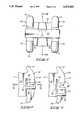
- FIG. 1is an elevational view of an assembled bracket with the cover in a closed position
- FIG. 2is a side view of the bracket
- FIG. 3is a side view of the bracket with the cover in an open position
- FIG. 4is a bottom view of the bracket
- FIG. 5is a sectional view as seen along line 5--5 in FIG. 1;
- FIG. 6is a sectional view similar to FIG. 5, showing the cover in an open position
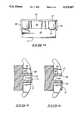
- FIG. 7is a sectional view taken along line 7--7 in FIG. 2;
- FIG. 8is a perspective view of the closure shown in FIGS. 1-7;
- FIG. 9is an elevational view of a second embodiment of the bracket.
- FIG. 10is a side view of the bracket shown in FIG. 9;
- FIG. 11is a side view showing the closure in an open position
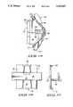
- FIG. 12is a bottom view of the bracket
- FIG. 13is a sectional view taken along line 13--13 in FIG. 9;
- FIG. 14is a cross-sectional view similar to FIG. 13, showing the closure in an open position
- FIG. 15is a side view of the bracket, illustrating use of a tying wire to retain the bracket on an archwire;
- FIG. 16is an elevational view of the closure
- FIG. 17is a side view of the closure.
- FIGS. 1-8Two illustrative forms of the self-locking orthodontic bracket are illustrated in the drawings.
- a first preferred embodimentis shown in FIGS. 1-8.
- An alternative embodimentis shown in FIGS. 9-17.
- the front surfaces of the bracketdirected outwardly from a supporting tooth, shall be referred to as anterior surfaces.
- the rear surfaces, which face toward the toothshall be termed posterior surfaces.
- Directions along the bracket generally parallel to the incisal or occlusal lineshall be referred to as having width and being transverse.
- perpendicular directions extending between the gingival line and the incisal or occlusal lineshall be referred to as the height of the bracket.
- the upright surfaces across the bracketshall be termed its side surfaces and the surfaces along the top and bottom of the bracket shall be termed the incisal or occlusal surface or the gingival surface.
- the incisal or occlusal surface and the gingival surface of the bracketare interrupted by projections that form cleats or anchors for tying wires and other attachment devices.
- the configurations of these extensionscan take any desired conventional or unconventional form.
- the extensions at the top and bottom of the bracketcan be located in different planes.
- the extensions at the top of the bracketcan be located in a plane different from that of the extensions at the bottom of the bracket.
- the extensionsmight also have the same or a different configuration at the top of the bracket than at the bottom of the bracket.
- the archwire slot across each bracketcan be oriented at any desired angular configuration relative to its incisal or occlusal surface.
- the archwire slots shown in the illustrative drawingsare aligned transversely across each bracket in a direction parallel to the incisal or occlusal surface for general illustration purposes.
- the illustrated bracketscan be bonded directly to a tooth or can be mounted on a tooth band for attachment to a tooth at either the facial or lingual tooth surfaces.
- the present bracketcan be made from any suitable material, including metals, plastics and ceramics, as well as a combination of such materials.
- the bracket and closurehave generally been designed to be fabricated of metal, but the choice of materials is not critical to understanding or using this invention. The only limitation with regard to materials is the ability to efficiently fabricate or mold the bracket and closure as a cooperative mechanism to engage an archwire during orthodontic procedures.
- FIGS. 1-7The general concepts of the invention can best be understood from a study of the first embodiment of the assembled orthodontic bracket, illustrated in FIGS. 1-7.
- This form of the bracketincludes a movable closure separately shown in FIG. 8.
- the illustrated bracketincludes a supportive base 10 having a posterior surface 11 adapted to be bonded to a tooth or tooth band.
- a pair of tying lugs 12project anteriorly from base 10.
- Each lug 12includes opposed extensions 13 and 14 that project outwardly between transversely spaced side surfaces formed on the bracket.
- the tying lugs 12each include an outer side surface 15.
- the tying lug configurations shown in the drawingsfurther include inwardly facing side surfaces 16 formed across each tying lug 12.
- the bracketalso includes an anterior surface 17 across the front of each tying lug 12.
- the anterior surface 17is illustrated as being planar, but can be curved if desired. It is interrupted by the opening of a transverse archwire slot formed distally from the anterior surface 17.
- the archwire slotspans the full width of the bracket, where it opens across the bracket side surfaces 15 (see FIGS. 2, 3 and 7).
- the archwire slotincludes side slot surfaces 18 and an anterior slot surface 20.
- the slot surfaces 18 and 20are sized and configured in a manner complementary to the size and shape requirements of an archwire (or archwires) adapted to be received within the archwire slot. While the illustrated slot is rectangular and is designed specifically for reception of a complementary rectangular archwire, it is to be understood that the slot can be configured as a cylinder or other cross-sectional shape in the manner presently known with respect to orthodontic bracket design. In use, the slot is partially or completely filled by the cross-sectional configuration of one or more archwires located within it.
- a closure complementary to the archwire slotis also provided on the illustrated bracket. It includes a movable cover 21 that slidably engages the anterior surface 17. Cover 21 has a width that spans the full width of the tying lugs 12 between their respective side surfaces 15. Its perpendicular width is greater than the corresponding width across the archwire slot at the anterior surface 17 of the bracket.
- the closurefurther includes a pair of guides 22 spaced transversely apart from one another along the width of the bracket.
- the guidesslidably engage opposed side surfaces 15 within complementary grooves 23. Movement of the cover and guides relative to the tying lugs 12 alternately positions the closure in (1) a first position with the cover clear of the archwire slot (FIGS. 2, 5) or (2) a second position with the cover 21 overlapping the width and height of the archwire slot (FIGS. 3, 6).
- bracketswhich include transversely spaced tying lugs protruding from a supporting base.
- additional strength and the benefits of an enclosed archwire tubecan be imparted to this bracket by also providing a fixed transverse wall extending between the inner side surfaces 16 of the respective tying lugs 12. This wall, shown at 24, structurally interconnects the tying lugs 12 and base 10.
- Wall 24includes inner surfaces 25 aligned with the side slot surfaces 18 in the respective tying lugs 12. Either the wall 24 or base 10 also presents a perpendicular transverse surface 26 aligned with the anterior slot surfaces 20 along the respective tying lugs 12. The resulting open slot along the bracket is formed continuously from one side of it to the other, thereby eliminating the sharp edged corners that would otherwise be presented at the inner side surfaces 16 of the tying lugs 12.
- Wall 24is illustrated as a rather narrow structure spanning the two sides of the transverse archwire slot. However, it is to be understood that the thickness of wall 24 can be expanded to encompass the full height of the bracket across the illustrated base 10, while still leaving extensions 13 and 14 protruding openly at the top and bottom of the bracket.
- Cover 21 and guides 22are structurally interconnected by an interposed pair of rigid support members shown at 30.
- the support members 30, together with cover 21 and guides 22form a separable closure generally illustrated in FIG. 8.
- This closurecan be molded or fabricated independently from the bracket. It should be assembled on the bracket prior to installation of the bracket on a tooth ot tooth band. While the closure is normally retained on the bracket during its use, it can be forced free from the bracket for replacement purposes or when use of the closure is not required.
- the design of the bracket and closureshould be such that removal of the closure can only be achieved by substantial prying movement, such as might be applied through use of a scaler.
- cover 21be releasably locked in its closed position to ensure against accidental release of an archwire received within the archwire slot.
- Releasable detents or lockscan be provided between the cover 21 and the bracket or between the guides 22 and the bracket.
- the open edge of cover 21has an inwardly recessed groove 27 formed along its transverse center.
- the groove 27releasably engages a complementary ridge 28 formed along the transverse center of the overlapped anterior surface of transverse wall 24. While generally rigid, the cover 21 must then have sufficient flexibility to yield slightly to ride over the ridge 28 as the cover 21 is moved between its operative positions.
- cover 21not be accidentally released from engagement with the supporting bracket structure while within the mouth of a patient.
- Thiscan be achieved by provision of positive stops on the guides 22 to limit their extent of sliding movement along the receiving grooves 23. Removal of cover 21 might also be prevented by protrusions (not shown) that extend outwardly from side surfaces 15 in the path of the rigid support members 30 that interconnect cover 21 and guides 22. In the embodiment illustrated, outward movement of cover 21 is limited by the extent of groove 27, which terminates short of the adjacent side edge along the bracket.
- the bracket and closureare preferably mounted on a tooth with the open edge of the closure facing toward the gingival line.
- the support members 30are respectively located adjacent to the side surfaces 15 across the tying lugs 12. Each support member 30 leads posteriorly from the cover 21 to one of the guides 22.
- the sliding guides 22are illustrated as being parallel to the portions of the anterior surface 17 slidably engaged by cover 21.
- the movement imparted to the supported cover 21will maintain it in a parallel position with its inner surface flush against the overlapped areas of anterior surface 17. This will maintain cover 21 in a closely adjacent position to the stationary bracket structure regardless of whether cover 21 is in its open or closed positions.
- the guides 22 and grooves 23might be similarly curved to achieve the desired flush sliding relationship between surface 17 and cover 21.
- cover 21When in its open position, as shown in FIGS. 3 and 6, cover 21 will leave the slot clear for movement of an archwire into or out from the slot.
- the protruding extensions 13at all times remain clear and accessible for tying or attachment purposes.
- Guides 22are located on the bracket in positions that are posterior to the open slot formed transversely through it. As can be seen in FIGS. 2 and 3, the support members 30 are offset from the center line of the closure to assure that there is adequate clearance across the full width of the archwire slot when the cover 21 is in its closed position. Thus, transverse sliding movement of the guides 22 and support members 30 does not block or restrict access to any portion of the open transverse archwire slot.
- FIGS. 9-17illustrate a second form of the invention in which the transverse separation of the tying lugs across the supportive base is more pronounced.
- the elements of the bracket and cover common to those previously disclosed hereinwill not be described again in repetitious detail.
- the second embodiment of the improved bracketalso includes a mounting base 40 having a posterior surface 41.
- a pair of transversely spaced tying lugs 42project anteriorly from base 40. They include extensions 43 and 44, which project from the bracket between outer and inner side surfaces 45 and 46 across the tying lugs 42.
- An anterior surface 47is presented along the front of the bracket across the respective tying lugs 42.
- An archwire slotextends transversely through each tying lug 42. It includes side slot surfaces 48 and a anterior slot surface 50.
- the closure as shown in FIGS. 9-17includes a movable cover 51 supported by a pair of guides 52.
- the guides 52are slidably engaged within complementary grooves 53 formed across the inner side surfaces 46 of the respective tying lugs 42. Grooves 53 and guides 52 are located posteriorly with respect to the anterior slot surface 50 of the archwire slot.
- a transverse wall 54spans the two tying lugs 42. It is preferably molded integrally with the tying lugs 42 and base 40. An inner surface 55 along wall 54 is aligned with one side slot surface 48 as an integral extension of it, thereby forming a continuous side slot surface extending the full width of the illustrated bracket.
- the closure of the second embodimentlike that of the first, has a structure that is complementary to the archwire slot. Since the inner surface 55 of transverse wall 54 is coextensive and flush with at least a portion of the inner archwire slot surfaces, namely one side slot surface 48, the remaining surfaces required to complete the archwire slot in the space between tying lugs 42 must be supplied by the movable closure. As shown, these surfaces are provided on support members 56 and 57 that structurally interconnect cover 51 to guides 52.
- structural member 56is perpendicular to the attached cover 51. It has an inner surface 58 aligned with the remaining side slot surface 48 along the archwire slot.
- Structural member 57is a shelf arranged in a position that is parallel to cover 51. Guides 52 are formed as outward extensions along its opposed sides. An inner surface 60 along structural member 57 is aligned with the anterior slot surface 50 of the archwire slot when the cover 51 is in its closed position.
- Structural member 57is also provided with an upturned side 61 that can serve as a manual handle or grip to facilitate opening or closing of cover 51 relative to the supporting orthodontic bracket.
- the opposite side of structural member 57is shown with an upturned central section 62 that can serve as a stop capable of abutting transverse wall 54 and limiting the extent of opening movement that can be imparted to cover 51.
- An inwardly facing central groove 63 adjacent to the free edge of cover 51 and a complementary ridge 64 across the top central section of transverse wall 54are illustrative of a detent or lock for maintaining cover 51 in its closed position overlapping the archwire slot.
- the closure that completes the archwire slotcomprises a slidable mechanism supported on the bracket at a location that is behind or posterior to the archwire slot boundaries.
- Sliding support for the closurecan be provided either along inwardly facing side surfaces or outwardly facing side surfaces of the bracket.
- the closureis movable between a first position clear of the archwire slot and a second position overlapping the its width and height.
- the closurecan also supply complementary surfaces movable between the lugs to fully complete a continuous archwire tube across the full width of the bracket.
- the closuredoes not impede normal access to and use of the tying lugs.
- the extensions that protrude to the sides of the orthodontic bracketremain unobstructed at all times.
- the bracketcan therefore be used to apply torsional forces to a tooth to rotate it about a desired axis or to use ligatures to interconnect the bracket and archwire where this is required.
- FIG. 15illustrates the use of a tie wire 65 wrapped about extensions 43 of the second illustrated embodiment of the invention.
- a conventional tie wire 65might be used to secure the bracket to an archwire 66 when the current position of the attached tooth is such that the archwire 66 cannot be completely positioned within the archwire slot of the bracket at a particular stage during orthodontic treatment.
- tie wires 65By leaving the closure open and using tie wires 65 to move the tooth relative to the archwire 66, a practitioner can utilize the present bracket at treatment stages prior to that at which use of the self-locking feature of the bracket becomes practical.
- tying wires, bands and other devicescan be attached to the extensions of the bracket at any time to apply rotative forces or attach other orthodontic devices to the bracket.
- the tube structureeliminates the corners conventionally encountered along the slotted lugs on dual or Siamese orthodontic brackets. These corners typically exert binding forces on the archwire, which impede tooth movement by the resulting concentration of frictional forces along the width of the archwire.
- the continuous tube formed by the preferred forms of this inventionassures freedom of movement of the bracket relative to the archwire, thereby increasing the rate of tooth movement and reducing the need for frequent manual readjustment of the brackets during treatment.
- the archwirewhen properly received within the archwire slot of the bracket, is at least flush with the outer or anterior surface of the bracket. Proper reception of the archwire within the receiving archwire slot and the ability to close the cover over the archwire can therefore be readily confirmed by visual inspection of the bracket within the mouth. This is contrasted with the difficulty of gauging the archwire positions within earlier brackets having slidable closures recessed beneath the anterior surface.
Landscapes
- Health & Medical Sciences (AREA)
- Oral & Maxillofacial Surgery (AREA)
- Dentistry (AREA)
- Epidemiology (AREA)
- Life Sciences & Earth Sciences (AREA)
- Animal Behavior & Ethology (AREA)
- General Health & Medical Sciences (AREA)
- Public Health (AREA)
- Veterinary Medicine (AREA)
- Dental Tools And Instruments Or Auxiliary Dental Instruments (AREA)
Abstract
Description
Claims (24)
Priority Applications (11)
| Application Number | Priority Date | Filing Date | Title |
|---|---|---|---|
| US08/045,529US5275557A (en) | 1993-04-08 | 1993-04-08 | Self-locking orthodontic bracket |
| US08/140,690US5429500A (en) | 1993-04-08 | 1993-10-20 | Self-locking orthodontic bracket |
| US08/140,689US5439378A (en) | 1993-04-08 | 1993-10-20 | Orthodontic bracket assembly and method of installation |
| DE69413527TDE69413527T2 (en) | 1993-04-08 | 1994-04-07 | ORTHODONTIC CLAMP UNIT |
| CA002160130ACA2160130C (en) | 1993-04-08 | 1994-04-07 | Orthodontic bracket assembly and method of installation |
| EP94913375AEP0692951B1 (en) | 1993-04-08 | 1994-04-07 | Orthodontic bracket assembly |
| AT94913375TATE171361T1 (en) | 1993-04-08 | 1994-04-07 | ORTHODONTIC BRACKET UNIT |
| AU65562/94AAU680898B2 (en) | 1993-04-08 | 1994-04-07 | Orthodontic bracket assembly and method of installation |
| PCT/US1994/003803WO1994023666A1 (en) | 1993-04-08 | 1994-04-07 | Orthodontic bracket assembly and method of installation |
| US08/267,188US5466151A (en) | 1993-04-08 | 1994-06-28 | Spring-locked orthodontic bracket |
| PCT/US1995/003721WO1996000533A1 (en) | 1993-04-08 | 1995-03-23 | Spring-locked orthodontic bracket |
Applications Claiming Priority (1)
| Application Number | Priority Date | Filing Date | Title |
|---|---|---|---|
| US08/045,529US5275557A (en) | 1993-04-08 | 1993-04-08 | Self-locking orthodontic bracket |
Related Child Applications (3)
| Application Number | Title | Priority Date | Filing Date |
|---|---|---|---|
| US08/140,690Continuation-In-PartUS5429500A (en) | 1993-04-08 | 1993-10-20 | Self-locking orthodontic bracket |
| US08/140,690ContinuationUS5429500A (en) | 1993-04-08 | 1993-10-20 | Self-locking orthodontic bracket |
| US08/140,689Continuation-In-PartUS5439378A (en) | 1993-04-08 | 1993-10-20 | Orthodontic bracket assembly and method of installation |
Publications (1)
| Publication Number | Publication Date |
|---|---|
| US5275557Atrue US5275557A (en) | 1994-01-04 |
Family
ID=21938427
Family Applications (1)
| Application Number | Title | Priority Date | Filing Date |
|---|---|---|---|
| US08/045,529Expired - LifetimeUS5275557A (en) | 1993-04-08 | 1993-04-08 | Self-locking orthodontic bracket |
Country Status (1)
| Country | Link |
|---|---|
| US (1) | US5275557A (en) |
Cited By (60)
| Publication number | Priority date | Publication date | Assignee | Title |
|---|---|---|---|---|
| US5429500A (en)* | 1993-04-08 | 1995-07-04 | Damon Family Limited Partnership | Self-locking orthodontic bracket |
| US5466151A (en)* | 1993-04-08 | 1995-11-14 | Damon Family Limited Partnership | Spring-locked orthodontic bracket |
| US5474446A (en)* | 1994-07-06 | 1995-12-12 | Wildman; Alexander J. | Miniature self-locking labial bracket with cam-release closure member |
| US5618176A (en)* | 1995-06-12 | 1997-04-08 | Ormco Corporation | Orthodontic bracket and ligature and method of ligating archwire to bracket |
| US5738513A (en)* | 1995-11-09 | 1998-04-14 | Hermann; Lawrence | Archwire locking device for orthodontic bracket |
| US5857850A (en)* | 1994-03-07 | 1999-01-12 | Voudouris; John C. | Orthodontic appliance |
| US6071118A (en)* | 1998-02-17 | 2000-06-06 | Damon Family Limited Partnership | Self-ligating orthodontic bracket |
| US6257883B1 (en)* | 1994-03-07 | 2001-07-10 | John C. Voudouris | Orthodontic bracket |
| US6347939B2 (en) | 1998-03-19 | 2002-02-19 | Norbert Abels | Self-ligating orthodontic bracket |
| WO2003051223A1 (en)* | 2001-12-14 | 2003-06-26 | 3M Innovative Properties Company | Orthodontic appliance with lingual retaining groove |
| US6607383B2 (en) | 2000-03-10 | 2003-08-19 | Norbert Abels | Orthodontic bracket |
| US6616445B2 (en) | 2001-02-15 | 2003-09-09 | Norbert Abels | Self-ligating orthodontic brackets having a spring element interconnecting the base and ligation cover |
| US6655957B2 (en) | 2001-02-15 | 2003-12-02 | Norbert Abels | Self-ligating orthodontic brackets formed from multiple plastic materials |
| US20040072117A1 (en)* | 2002-08-19 | 2004-04-15 | Ormco Corporation | Aesthetic self-ligating orthodontic bracket |
| US20040072119A1 (en)* | 2002-06-21 | 2004-04-15 | Orthoarm, Inc. | Self-ligating orthodontic bracket |
| US20040086826A1 (en)* | 2002-11-04 | 2004-05-06 | 3M Innovative Properties Company | Molar appliance for orthodontic therapy |
| US20040157186A1 (en)* | 2001-09-12 | 2004-08-12 | Norbert Abels | Self-ligating orthodontic brackets including a metal ligation cover hingedly connected to a bracket base |
| US20040175667A1 (en)* | 2003-03-04 | 2004-09-09 | Norbert Abels | Orthodontic brackets with elongate film hinge |
| US20040175668A1 (en)* | 2003-03-04 | 2004-09-09 | Norbert Abels | Orthodontic brackets with elongate film hinge |
| US20050186525A1 (en)* | 2004-02-19 | 2005-08-25 | Norbert Abels | Two-part orthodontic bracket |
| US20050231476A1 (en)* | 1996-07-05 | 2005-10-20 | Armstrong Brad A | Image controller |
| US20050239012A1 (en)* | 2002-11-26 | 2005-10-27 | Juergen Bathen | Orthodontic bracket |
| US20050255422A1 (en)* | 2004-05-11 | 2005-11-17 | Cordato Mark A | Orthodontic bracket and clip |
| US20060051721A1 (en)* | 2002-11-26 | 2006-03-09 | Luis Carriere Lluch | Improvements to orthodontic supports applicable to teeth |
| US20060154196A1 (en)* | 2005-01-11 | 2006-07-13 | Ormco Corporation | Self-ligating orthodontic bracket |
| US20060199137A1 (en)* | 2005-03-04 | 2006-09-07 | Norbert Abels | Orthodontic retainer system with removable retaining wire |
| US20060228662A1 (en)* | 2005-04-08 | 2006-10-12 | Lokar Robert R | Low profile self-ligating bracket assembly and method of use |
| US20070009849A1 (en)* | 2005-07-11 | 2007-01-11 | Wool Arthur L | Self-locking orthodontic bracket |
| US20070166658A1 (en)* | 2006-01-13 | 2007-07-19 | Ceramic Sciences, Inc. | Self-ligating orthodontic bracket with mid-undercut |
| US20070243497A1 (en)* | 2006-04-18 | 2007-10-18 | Ceramic Sciences Incorporated | Orthodontic bracket assembly |
| US20070259304A1 (en)* | 2006-05-04 | 2007-11-08 | Rolf Hagelganz | Self-ligating bracket with rotary cover |
| US20080241782A1 (en)* | 2007-03-30 | 2008-10-02 | Norbert Abels | Two-part self-ligating orthodontic bracket having lateral guiding mechanism |
| US20090004619A1 (en)* | 2007-06-28 | 2009-01-01 | Ormco Corporation | Self-ligating orthodontic bracket and devices for deploying same |
| US20090155734A1 (en)* | 2006-04-19 | 2009-06-18 | Damon Dwight H | Orthodontic bracket |
| US20090162807A1 (en)* | 2006-05-04 | 2009-06-25 | World Class Technology Corporation | Orthodontic bracket with rotary ligating cover |
| WO2009116560A1 (en)* | 2008-03-18 | 2009-09-24 | デンツプライ三金株式会社 | Orthodontic bracket |
| US20090325120A1 (en)* | 2007-07-23 | 2009-12-31 | Ultradent Products, Inc. | Self-ligating orthodontic bracket with sliding ligation cover |
| US20100178629A1 (en)* | 2007-06-28 | 2010-07-15 | Ormco Corporation | Self-ligating orthodontic bracket and devices for deploying same |
| US20100196838A1 (en)* | 2006-04-19 | 2010-08-05 | Ormco Corporation | Orthodontic bracket |
| US20100285420A1 (en)* | 2009-05-07 | 2010-11-11 | Ormco Corporation | Orthodontic bracket having a lingually biased closure member and associated method |
| US20100311004A1 (en)* | 2009-06-03 | 2010-12-09 | Voudouris John C | Self-ligating orthodontic bracket |
| US20110076633A1 (en)* | 2009-09-30 | 2011-03-31 | Orthodontic Design And Production, Inc. | Self-ligating orthodontic bracket |
| US20110081622A1 (en)* | 2009-10-05 | 2011-04-07 | Cameron Mashouf | Self-ligating bracket with universal application |
| USD648030S1 (en) | 2011-01-25 | 2011-11-01 | Orthodontic Design And Production, Inc. | Self-ligating orthodontic bracket |
| US8568139B2 (en) | 2011-11-23 | 2013-10-29 | Ronald M Roncone | Orthodontic bracket |
| US8622738B2 (en)* | 2010-12-14 | 2014-01-07 | Michael Stuart Johnston | Orthodontic brace system and method |
| US20140038120A1 (en)* | 2011-04-19 | 2014-02-06 | 3M Innovative Properties Company | Self-ligating orthodontic appliance and related methods |
| WO2014078564A1 (en)* | 2012-11-16 | 2014-05-22 | World Class Technology Corporation | Self-ligating orthodontic appliance with sliding cover |
| US9345558B2 (en) | 2010-09-03 | 2016-05-24 | Ormco Corporation | Self-ligating orthodontic bracket and method of making same |
| US9364298B2 (en) | 2012-11-08 | 2016-06-14 | Ormco Corporation | Orthodontic bracket having a biased slide member |
| US9468505B2 (en) | 2013-03-15 | 2016-10-18 | American Orthodontics Corporation | Self-ligating bracket |
| US9532853B2 (en) | 2013-03-15 | 2017-01-03 | Ormco Corporation | Self-ligating orthodontic bracket and method of using the same |
| US9943383B2 (en) | 2014-12-19 | 2018-04-17 | Ormco Corporation | Biased pivoting slide orthodontic bracket |
| US10080628B2 (en) | 2015-06-08 | 2018-09-25 | American Orthodontics Corporation | Self-ligating bracket |
| US10111731B2 (en) | 2014-11-18 | 2018-10-30 | American Orthodontics Corporation | Self-ligating bracket |
| US10772708B2 (en) | 2008-08-13 | 2020-09-15 | Ormco Corporation | Aesthetic orthodontic bracket and method of making same |
| CN112603567A (en)* | 2021-01-19 | 2021-04-06 | 上海市徐汇区牙病防治所 | Auxiliary front tooth torque control device |
| US20220331068A1 (en)* | 2021-04-16 | 2022-10-20 | Braces On Demand Inc. | Self-ligating orthodontic appliances |
| US20230181290A1 (en)* | 2021-12-09 | 2023-06-15 | Peking University School Of Stomatology | Self-ligating crossed buccal tubes |
| US12350123B2 (en) | 2020-12-23 | 2025-07-08 | Hirsch Dynamics Holding Ag | Self-ligating orthodontic bracket |
Citations (34)
| Publication number | Priority date | Publication date | Assignee | Title |
|---|---|---|---|---|
| US1280628A (en)* | 1916-11-28 | 1918-10-08 | Edward H Angle | Orthodontic appliance. |
| US1821171A (en)* | 1929-10-28 | 1931-09-01 | Spencer R Atkinson | Orthodontic appliance |
| US2230315A (en)* | 1939-04-21 | 1941-02-04 | Seymour L Winslow | Orthodontic applicance |
| US2671964A (en)* | 1952-12-10 | 1954-03-16 | Russell Harry John | Orthodontic appliance |
| US3091857A (en)* | 1961-02-15 | 1963-06-04 | James M Rubin | Orthodontic device |
| US3128552A (en)* | 1960-04-13 | 1964-04-14 | Williams Gold Refining Co | Orthodontic appliance |
| US3131474A (en)* | 1961-09-05 | 1964-05-05 | Unitek Corp | Orthodontic appliance |
| US3497954A (en)* | 1968-07-03 | 1970-03-03 | Peter C Kesling | Bypass clamp for orthodontic bracket |
| US3835539A (en)* | 1972-11-08 | 1974-09-17 | M Wallshein | Orthodontic appliance |
| US4015334A (en)* | 1975-10-15 | 1977-04-05 | Dan Moss | Posterior direct bond orthodontic unit segment |
| US4023274A (en)* | 1975-06-02 | 1977-05-17 | Melvin Wallshein | Orthodontic spring clip |
| US4144642A (en)* | 1976-07-26 | 1979-03-20 | Melvin Wallshein | Retainer members for orthodontic brackets |
| US4180912A (en)* | 1978-09-22 | 1980-01-01 | Kesling Peter C | Orthodontic light wire appliance |
| US4197642A (en)* | 1977-09-29 | 1980-04-15 | Melvin Wallshein | Bent wire orthodontic spring clip |
| US4209906A (en)* | 1976-12-23 | 1980-07-01 | Kinya Fujita | Orthodontic appliance (bracket and lock pin) |
| US4242085A (en)* | 1978-11-13 | 1980-12-30 | Melvin Wallshein | Multi-purpose orthodontic bracket |
| US4248588A (en)* | 1979-04-27 | 1981-02-03 | Hanson Gustaf H | Orthodontic bracket and arch wire |
| US4260375A (en)* | 1979-12-13 | 1981-04-07 | Melvin Wallshein | Bent wire orthodontic spring clip |
| US4355975A (en)* | 1980-02-08 | 1982-10-26 | Kinya Fujita | Orthodontic appliance |
| US4386909A (en)* | 1982-04-12 | 1983-06-07 | Augusta Developments Inc. | Orthodontic arch wires |
| US4419078A (en)* | 1981-05-20 | 1983-12-06 | Pletcher Erwin Carroll | Orthodontic bracket |
| US4492573A (en)* | 1984-03-27 | 1985-01-08 | Augusta Developments Inc. | Orthodontic bracket |
| US4561844A (en)* | 1984-10-09 | 1985-12-31 | Bates Lyn V | Orthodontic bracket |
| US4583944A (en)* | 1985-01-10 | 1986-04-22 | Augusta Developments Inc. | Orthodontic devices |
| US4698017A (en)* | 1986-12-10 | 1987-10-06 | Hanson Gustaf H | Orthodontic brackets |
| US4712999A (en)* | 1986-09-10 | 1987-12-15 | Farel Rosenberg | Convertible, self-ligating, archwire positioning orthodontic bracket |
| US4838787A (en)* | 1987-09-15 | 1989-06-13 | Harry Lerner | Orthodontic bracket and lock pin |
| US4850865A (en)* | 1987-04-30 | 1989-07-25 | Napolitano John R | Orthodontic method and apparatus |
| US4859179A (en)* | 1986-11-26 | 1989-08-22 | Tp Orthodontics, Inc. | Edgewise bracket with Sved shaped slot and control means |
| US5018259A (en)* | 1988-09-21 | 1991-05-28 | Wildman Alexander J | Method of design and manufacture of laminated orthodontic brackets |
| US5094614A (en)* | 1991-03-08 | 1992-03-10 | Wildman Alexander J | Miniature self-locking labial bracket |
| US5123838A (en)* | 1990-12-13 | 1992-06-23 | Cannon James L | Orthodontic bracket |
| US5154607A (en)* | 1991-05-13 | 1992-10-13 | Herbert Hanson | Low friction orthodontic brackets |
| US5174753A (en)* | 1990-07-24 | 1992-12-29 | Wool Arthur L | Orthodontic arch wire having a non-symmetrical trapezoidal cross-section |
- 1993
- 1993-04-08USUS08/045,529patent/US5275557A/ennot_activeExpired - Lifetime
Patent Citations (34)
| Publication number | Priority date | Publication date | Assignee | Title |
|---|---|---|---|---|
| US1280628A (en)* | 1916-11-28 | 1918-10-08 | Edward H Angle | Orthodontic appliance. |
| US1821171A (en)* | 1929-10-28 | 1931-09-01 | Spencer R Atkinson | Orthodontic appliance |
| US2230315A (en)* | 1939-04-21 | 1941-02-04 | Seymour L Winslow | Orthodontic applicance |
| US2671964A (en)* | 1952-12-10 | 1954-03-16 | Russell Harry John | Orthodontic appliance |
| US3128552A (en)* | 1960-04-13 | 1964-04-14 | Williams Gold Refining Co | Orthodontic appliance |
| US3091857A (en)* | 1961-02-15 | 1963-06-04 | James M Rubin | Orthodontic device |
| US3131474A (en)* | 1961-09-05 | 1964-05-05 | Unitek Corp | Orthodontic appliance |
| US3497954A (en)* | 1968-07-03 | 1970-03-03 | Peter C Kesling | Bypass clamp for orthodontic bracket |
| US3835539A (en)* | 1972-11-08 | 1974-09-17 | M Wallshein | Orthodontic appliance |
| US4023274A (en)* | 1975-06-02 | 1977-05-17 | Melvin Wallshein | Orthodontic spring clip |
| US4015334A (en)* | 1975-10-15 | 1977-04-05 | Dan Moss | Posterior direct bond orthodontic unit segment |
| US4144642A (en)* | 1976-07-26 | 1979-03-20 | Melvin Wallshein | Retainer members for orthodontic brackets |
| US4209906A (en)* | 1976-12-23 | 1980-07-01 | Kinya Fujita | Orthodontic appliance (bracket and lock pin) |
| US4197642A (en)* | 1977-09-29 | 1980-04-15 | Melvin Wallshein | Bent wire orthodontic spring clip |
| US4180912A (en)* | 1978-09-22 | 1980-01-01 | Kesling Peter C | Orthodontic light wire appliance |
| US4242085A (en)* | 1978-11-13 | 1980-12-30 | Melvin Wallshein | Multi-purpose orthodontic bracket |
| US4248588A (en)* | 1979-04-27 | 1981-02-03 | Hanson Gustaf H | Orthodontic bracket and arch wire |
| US4260375A (en)* | 1979-12-13 | 1981-04-07 | Melvin Wallshein | Bent wire orthodontic spring clip |
| US4355975A (en)* | 1980-02-08 | 1982-10-26 | Kinya Fujita | Orthodontic appliance |
| US4419078A (en)* | 1981-05-20 | 1983-12-06 | Pletcher Erwin Carroll | Orthodontic bracket |
| US4386909A (en)* | 1982-04-12 | 1983-06-07 | Augusta Developments Inc. | Orthodontic arch wires |
| US4492573A (en)* | 1984-03-27 | 1985-01-08 | Augusta Developments Inc. | Orthodontic bracket |
| US4561844A (en)* | 1984-10-09 | 1985-12-31 | Bates Lyn V | Orthodontic bracket |
| US4583944A (en)* | 1985-01-10 | 1986-04-22 | Augusta Developments Inc. | Orthodontic devices |
| US4712999A (en)* | 1986-09-10 | 1987-12-15 | Farel Rosenberg | Convertible, self-ligating, archwire positioning orthodontic bracket |
| US4859179A (en)* | 1986-11-26 | 1989-08-22 | Tp Orthodontics, Inc. | Edgewise bracket with Sved shaped slot and control means |
| US4698017A (en)* | 1986-12-10 | 1987-10-06 | Hanson Gustaf H | Orthodontic brackets |
| US4850865A (en)* | 1987-04-30 | 1989-07-25 | Napolitano John R | Orthodontic method and apparatus |
| US4838787A (en)* | 1987-09-15 | 1989-06-13 | Harry Lerner | Orthodontic bracket and lock pin |
| US5018259A (en)* | 1988-09-21 | 1991-05-28 | Wildman Alexander J | Method of design and manufacture of laminated orthodontic brackets |
| US5174753A (en)* | 1990-07-24 | 1992-12-29 | Wool Arthur L | Orthodontic arch wire having a non-symmetrical trapezoidal cross-section |
| US5123838A (en)* | 1990-12-13 | 1992-06-23 | Cannon James L | Orthodontic bracket |
| US5094614A (en)* | 1991-03-08 | 1992-03-10 | Wildman Alexander J | Miniature self-locking labial bracket |
| US5154607A (en)* | 1991-05-13 | 1992-10-13 | Herbert Hanson | Low friction orthodontic brackets |
Cited By (131)
| Publication number | Priority date | Publication date | Assignee | Title |
|---|---|---|---|---|
| US5429500A (en)* | 1993-04-08 | 1995-07-04 | Damon Family Limited Partnership | Self-locking orthodontic bracket |
| US5466151A (en)* | 1993-04-08 | 1995-11-14 | Damon Family Limited Partnership | Spring-locked orthodontic bracket |
| US6257883B1 (en)* | 1994-03-07 | 2001-07-10 | John C. Voudouris | Orthodontic bracket |
| US5857850A (en)* | 1994-03-07 | 1999-01-12 | Voudouris; John C. | Orthodontic appliance |
| US20040166459A1 (en)* | 1994-03-07 | 2004-08-26 | Orthoarm, Inc. | Orthodontic bracket |
| US20060269889A1 (en)* | 1994-03-07 | 2006-11-30 | Orthoarm, Inc. | Orthodontic bracket |
| US20020132206A1 (en)* | 1994-03-07 | 2002-09-19 | Voudouris John C. | Orthodontic bracket |
| US20060269895A1 (en)* | 1994-03-07 | 2006-11-30 | Voudouris John C | Orthodontic bracket |
| US6939133B2 (en) | 1994-03-07 | 2005-09-06 | Orthoarm, Inc. | Orthodontic bracket |
| US5613850A (en)* | 1994-07-06 | 1997-03-25 | Wildman; Alexander J. | Miniature self-locking labial bracket with cam-release closure member |
| US5474446A (en)* | 1994-07-06 | 1995-12-12 | Wildman; Alexander J. | Miniature self-locking labial bracket with cam-release closure member |
| US5618176A (en)* | 1995-06-12 | 1997-04-08 | Ormco Corporation | Orthodontic bracket and ligature and method of ligating archwire to bracket |
| US5738513A (en)* | 1995-11-09 | 1998-04-14 | Hermann; Lawrence | Archwire locking device for orthodontic bracket |
| US6042373A (en)* | 1995-11-09 | 2000-03-28 | Hermann; Lawrence | Archwire locking device for orthodontic bracket |
| US20050231476A1 (en)* | 1996-07-05 | 2005-10-20 | Armstrong Brad A | Image controller |
| US6071118A (en)* | 1998-02-17 | 2000-06-06 | Damon Family Limited Partnership | Self-ligating orthodontic bracket |
| US6347939B2 (en) | 1998-03-19 | 2002-02-19 | Norbert Abels | Self-ligating orthodontic bracket |
| US6607383B2 (en) | 2000-03-10 | 2003-08-19 | Norbert Abels | Orthodontic bracket |
| US6659767B2 (en) | 2001-02-15 | 2003-12-09 | Norbert Abels | Self-ligating orthodontic brackets that include a deformable ligation cover to facilitate locking and unlocking |
| US6695612B2 (en) | 2001-02-15 | 2004-02-24 | Norbert Abels | Self-ligating orthodontic brackets including a ligation cover biased toward an open or closed position |
| US6655958B2 (en) | 2001-02-15 | 2003-12-02 | Norbert Abels | Self-ligating orthodontic brackets that include a film hinge |
| US6733286B2 (en) | 2001-02-15 | 2004-05-11 | Norbert Abels | Self-ligating orthodontic brackets that have multiple initially open arch wire slots ligatable with a single cover |
| US6659766B2 (en) | 2001-02-15 | 2003-12-09 | Norbert Abels | Self-ligating orthodontic brackets having a safety locking feature for ligation cover |
| US6655957B2 (en) | 2001-02-15 | 2003-12-02 | Norbert Abels | Self-ligating orthodontic brackets formed from multiple plastic materials |
| US6616445B2 (en) | 2001-02-15 | 2003-09-09 | Norbert Abels | Self-ligating orthodontic brackets having a spring element interconnecting the base and ligation cover |
| US6932597B2 (en) | 2001-09-12 | 2005-08-23 | Norbert Abels | Self-ligating orthodontic brackets including a metal ligation cover hingedly connected to a bracket base |
| US20060084025A1 (en)* | 2001-09-12 | 2006-04-20 | Norbert Abels | Self-ligating orthodontic brackets including a metal ligation cover hingedly connected to a bracket base |
| US7210927B2 (en) | 2001-09-12 | 2007-05-01 | Norbert Abels | Self-ligating orthodontic brackets including a metal ligation cover hingedly connected to a bracket base |
| US20040157186A1 (en)* | 2001-09-12 | 2004-08-12 | Norbert Abels | Self-ligating orthodontic brackets including a metal ligation cover hingedly connected to a bracket base |
| WO2003051223A1 (en)* | 2001-12-14 | 2003-06-26 | 3M Innovative Properties Company | Orthodontic appliance with lingual retaining groove |
| US6733285B2 (en) | 2001-12-14 | 2004-05-11 | 3M Innovative Properties Company | Orthodontic appliance with lingual retaining groove |
| US20040072119A1 (en)* | 2002-06-21 | 2004-04-15 | Orthoarm, Inc. | Self-ligating orthodontic bracket |
| US9827073B2 (en) | 2002-08-19 | 2017-11-28 | Ormco Corporation | Aesthetic self-ligating orthodontic bracket |
| US8113827B2 (en) | 2002-08-19 | 2012-02-14 | Ormco Corporation | Aesthetic self-ligating orthodontic bracket |
| US20060177790A1 (en)* | 2002-08-19 | 2006-08-10 | Ormco Corporation | Aesthetic self-ligating orthodontic bracket |
| US20040072117A1 (en)* | 2002-08-19 | 2004-04-15 | Ormco Corporation | Aesthetic self-ligating orthodontic bracket |
| US20080311534A1 (en)* | 2002-08-19 | 2008-12-18 | Ormco Corporation | Aesthetic self-ligating orthodontic bracket |
| US7419375B2 (en) | 2002-08-19 | 2008-09-02 | Ormco Corporation | Aesthetic self-ligating orthodontic bracket |
| US7416408B2 (en) | 2002-08-19 | 2008-08-26 | Ormco Corporation | Aesthetic self-ligating orthodontic bracket |
| US20080070184A1 (en)* | 2002-08-19 | 2008-03-20 | Ormco Corporation | Aesthetic self-ligating orthodontic bracket |
| US20040086826A1 (en)* | 2002-11-04 | 2004-05-06 | 3M Innovative Properties Company | Molar appliance for orthodontic therapy |
| US6957957B2 (en) | 2002-11-04 | 2005-10-25 | 3M Innovative Properties Company | Molar appliance for orthodontic therapy |
| US20060051721A1 (en)* | 2002-11-26 | 2006-03-09 | Luis Carriere Lluch | Improvements to orthodontic supports applicable to teeth |
| US20050239012A1 (en)* | 2002-11-26 | 2005-10-27 | Juergen Bathen | Orthodontic bracket |
| US7621743B2 (en) | 2002-11-26 | 2009-11-24 | Orthodontic Research And Development, S.L. | Orthodontic bracket |
| US6960080B2 (en) | 2003-03-04 | 2005-11-01 | Norbert Abels | Orthodontic brackets with elongate film hinge |
| US20040175667A1 (en)* | 2003-03-04 | 2004-09-09 | Norbert Abels | Orthodontic brackets with elongate film hinge |
| US20040175668A1 (en)* | 2003-03-04 | 2004-09-09 | Norbert Abels | Orthodontic brackets with elongate film hinge |
| US6960081B2 (en) | 2003-03-04 | 2005-11-01 | Norbert Abels | Orthodontic brackets with elongate film hinge |
| US20050186525A1 (en)* | 2004-02-19 | 2005-08-25 | Norbert Abels | Two-part orthodontic bracket |
| US6964565B2 (en) | 2004-02-19 | 2005-11-15 | Norbert Abels | Two-part orthodontic bracket |
| US7033170B2 (en)* | 2004-05-11 | 2006-04-25 | Mark Andrew Cordato | Orthodontic bracket and clip |
| US20050255422A1 (en)* | 2004-05-11 | 2005-11-17 | Cordato Mark A | Orthodontic bracket and clip |
| US10751150B2 (en)* | 2005-01-11 | 2020-08-25 | Ormco Corporation | Self-ligating orthodontic bracket |
| US20070275342A1 (en)* | 2005-01-11 | 2007-11-29 | Ormco Corporation | Self-ligating orthodontic bracket |
| US7909603B2 (en) | 2005-01-11 | 2011-03-22 | Ormco Corporation | Self-ligating orthodontic bracket |
| US20160310240A1 (en)* | 2005-01-11 | 2016-10-27 | Ormco Corporation | Self-ligating orthodontic bracket |
| US7267545B2 (en) | 2005-01-11 | 2007-09-11 | Ormco Corporation | Self-ligating orthodontic bracket |
| US11065088B2 (en) | 2005-01-11 | 2021-07-20 | Ormco Corporation | Self-ligating orthodontic bracket |
| US20110195372A1 (en)* | 2005-01-11 | 2011-08-11 | Ormco Corporation | Self-ligating orthodontic bracket |
| US20060154196A1 (en)* | 2005-01-11 | 2006-07-13 | Ormco Corporation | Self-ligating orthodontic bracket |
| US8393896B2 (en) | 2005-01-11 | 2013-03-12 | Ormco Corporation | Self-ligating orthodontic bracket |
| US20060199137A1 (en)* | 2005-03-04 | 2006-09-07 | Norbert Abels | Orthodontic retainer system with removable retaining wire |
| US20060228662A1 (en)* | 2005-04-08 | 2006-10-12 | Lokar Robert R | Low profile self-ligating bracket assembly and method of use |
| US20070009849A1 (en)* | 2005-07-11 | 2007-01-11 | Wool Arthur L | Self-locking orthodontic bracket |
| US20070166658A1 (en)* | 2006-01-13 | 2007-07-19 | Ceramic Sciences, Inc. | Self-ligating orthodontic bracket with mid-undercut |
| US20070243497A1 (en)* | 2006-04-18 | 2007-10-18 | Ceramic Sciences Incorporated | Orthodontic bracket assembly |
| US9895207B2 (en) | 2006-04-19 | 2018-02-20 | Ormco Corporation | Orthodontic bracket |
| US20100196838A1 (en)* | 2006-04-19 | 2010-08-05 | Ormco Corporation | Orthodontic bracket |
| US9744004B2 (en) | 2006-04-19 | 2017-08-29 | Ormco Corporation | Orthodontic bracket |
| US9867680B2 (en) | 2006-04-19 | 2018-01-16 | Ormco Corporation | Orthodontic bracket |
| US9277973B2 (en) | 2006-04-19 | 2016-03-08 | Ormco Corporation | Orthodontic bracket |
| US10159544B2 (en) | 2006-04-19 | 2018-12-25 | Ormco Corporation | Orthodontic bracket |
| US20090155734A1 (en)* | 2006-04-19 | 2009-06-18 | Damon Dwight H | Orthodontic bracket |
| US11166790B2 (en) | 2006-04-19 | 2021-11-09 | Ormco Corporation | Orthodontic bracket |
| US7585171B2 (en) | 2006-05-04 | 2009-09-08 | World Class Technology Corporation | Orthodontic bracket with rotary ligating cover |
| US20090162807A1 (en)* | 2006-05-04 | 2009-06-25 | World Class Technology Corporation | Orthodontic bracket with rotary ligating cover |
| US7780443B2 (en) | 2006-05-04 | 2010-08-24 | World Class Technology Corporation | Self-ligating bracket with rotary cover |
| US20070259304A1 (en)* | 2006-05-04 | 2007-11-08 | Rolf Hagelganz | Self-ligating bracket with rotary cover |
| US7878802B2 (en) | 2006-05-04 | 2011-02-01 | World Class Technology Corporation | Orthodontic bracket with rotary ligating cover |
| US20080241782A1 (en)* | 2007-03-30 | 2008-10-02 | Norbert Abels | Two-part self-ligating orthodontic bracket having lateral guiding mechanism |
| US20100178629A1 (en)* | 2007-06-28 | 2010-07-15 | Ormco Corporation | Self-ligating orthodontic bracket and devices for deploying same |
| JP2013039382A (en)* | 2007-06-28 | 2013-02-28 | Ormco Corp | Self-ligating orthodontic bracket and device for deploying same |
| US8033824B2 (en) | 2007-06-28 | 2011-10-11 | Ormco Corporation | Self-ligating orthodontic bracket and devices for deploying same |
| US8469704B2 (en) | 2007-06-28 | 2013-06-25 | Ormco Corporation | Self-ligating orthodontic bracket and devices for deploying same |
| US20090004619A1 (en)* | 2007-06-28 | 2009-01-01 | Ormco Corporation | Self-ligating orthodontic bracket and devices for deploying same |
| US20090325120A1 (en)* | 2007-07-23 | 2009-12-31 | Ultradent Products, Inc. | Self-ligating orthodontic bracket with sliding ligation cover |
| US7963767B2 (en) | 2007-07-23 | 2011-06-21 | Ultradent Products, Inc. | Self-ligating orthodontic bracket with sliding ligation cover |
| US20110020762A1 (en)* | 2008-03-18 | 2011-01-27 | Dentsply-Sankin K.K. | Orthodontic bracket |
| WO2009116560A1 (en)* | 2008-03-18 | 2009-09-24 | デンツプライ三金株式会社 | Orthodontic bracket |
| JPWO2009116560A1 (en)* | 2008-03-18 | 2011-07-21 | デンツプライ三金株式会社 | Orthodontic bracket |
| US8297970B2 (en) | 2008-03-18 | 2012-10-30 | Dentsply-Sankin K. K. | Orthodontic bracket |
| US10799324B2 (en) | 2008-08-13 | 2020-10-13 | Ormco Corporation | Aesthetic orthodontic bracket and method of making same |
| US10772708B2 (en) | 2008-08-13 | 2020-09-15 | Ormco Corporation | Aesthetic orthodontic bracket and method of making same |
| US20100285420A1 (en)* | 2009-05-07 | 2010-11-11 | Ormco Corporation | Orthodontic bracket having a lingually biased closure member and associated method |
| US20100311004A1 (en)* | 2009-06-03 | 2010-12-09 | Voudouris John C | Self-ligating orthodontic bracket |
| US8636507B2 (en) | 2009-06-03 | 2014-01-28 | John C. Voudouris | Self-ligating orthodontic bracket |
| US20110076633A1 (en)* | 2009-09-30 | 2011-03-31 | Orthodontic Design And Production, Inc. | Self-ligating orthodontic bracket |
| US20110081622A1 (en)* | 2009-10-05 | 2011-04-07 | Cameron Mashouf | Self-ligating bracket with universal application |
| US9345558B2 (en) | 2010-09-03 | 2016-05-24 | Ormco Corporation | Self-ligating orthodontic bracket and method of making same |
| US8622738B2 (en)* | 2010-12-14 | 2014-01-07 | Michael Stuart Johnston | Orthodontic brace system and method |
| USD648030S1 (en) | 2011-01-25 | 2011-11-01 | Orthodontic Design And Production, Inc. | Self-ligating orthodontic bracket |
| US9492246B2 (en)* | 2011-04-19 | 2016-11-15 | 3M Innovative Properties Company | Self-ligating orthodontic appliance and related methods |
| US20140038120A1 (en)* | 2011-04-19 | 2014-02-06 | 3M Innovative Properties Company | Self-ligating orthodontic appliance and related methods |
| JP2014514116A (en)* | 2011-04-19 | 2014-06-19 | スリーエム イノベイティブ プロパティズ カンパニー | Self-ligating orthodontic appliance and related methods |
| US8568139B2 (en) | 2011-11-23 | 2013-10-29 | Ronald M Roncone | Orthodontic bracket |
| US9956059B2 (en) | 2012-11-08 | 2018-05-01 | Ormco Corporation | Orthodontic bracket having a biased slide member |
| US9364298B2 (en) | 2012-11-08 | 2016-06-14 | Ormco Corporation | Orthodontic bracket having a biased slide member |
| WO2014078564A1 (en)* | 2012-11-16 | 2014-05-22 | World Class Technology Corporation | Self-ligating orthodontic appliance with sliding cover |
| KR20150106403A (en)* | 2012-11-16 | 2015-09-21 | 월드 클래스 테크놀로지 코퍼레이션 | Self-ligating orthodontic appliance with sliding cover |
| EP2919700A4 (en)* | 2012-11-16 | 2016-08-10 | World Class Technology Corp | AUTOMATIC LIGATURE ORTHODONTIC APPARATUS AND SLIDING COVER |
| US9089386B2 (en) | 2012-11-16 | 2015-07-28 | World Class Technology Corporation | Self-ligating bracket with sliding cover |
| US10631957B2 (en) | 2012-11-16 | 2020-04-28 | World Class Technology Corporation | Self-ligating bracket with sliding cover |
| US10653505B2 (en) | 2013-03-15 | 2020-05-19 | American Orthodontics Corporation | Self-ligating bracket |
| US10111732B2 (en) | 2013-03-15 | 2018-10-30 | American Orthodontics Corporation | Self-ligating bracket |
| US9943384B2 (en) | 2013-03-15 | 2018-04-17 | Ormco Corporation | Self-ligating orthodontic bracket and method of using same |
| US9532853B2 (en) | 2013-03-15 | 2017-01-03 | Ormco Corporation | Self-ligating orthodontic bracket and method of using the same |
| US9468505B2 (en) | 2013-03-15 | 2016-10-18 | American Orthodontics Corporation | Self-ligating bracket |
| US10111731B2 (en) | 2014-11-18 | 2018-10-30 | American Orthodontics Corporation | Self-ligating bracket |
| US10912630B2 (en) | 2014-11-18 | 2021-02-09 | American Orthodontics Corporation | Self-ligating bracket |
| US12207988B2 (en) | 2014-11-18 | 2025-01-28 | American Orthodontics Corporation | Self-ligating bracket |
| US11517404B2 (en) | 2014-11-18 | 2022-12-06 | American Orthodontics Corporation | Self-ligating bracket |
| US9943383B2 (en) | 2014-12-19 | 2018-04-17 | Ormco Corporation | Biased pivoting slide orthodontic bracket |
| US10080628B2 (en) | 2015-06-08 | 2018-09-25 | American Orthodontics Corporation | Self-ligating bracket |
| US11058519B2 (en) | 2015-06-08 | 2021-07-13 | American Orthodontics Corporation | Self-ligating bracket |
| US11883257B2 (en) | 2015-06-08 | 2024-01-30 | American Orthodontics Corporation | Self-ligating bracket |
| US12350123B2 (en) | 2020-12-23 | 2025-07-08 | Hirsch Dynamics Holding Ag | Self-ligating orthodontic bracket |
| CN112603567A (en)* | 2021-01-19 | 2021-04-06 | 上海市徐汇区牙病防治所 | Auxiliary front tooth torque control device |
| US20220331068A1 (en)* | 2021-04-16 | 2022-10-20 | Braces On Demand Inc. | Self-ligating orthodontic appliances |
| US11903790B2 (en)* | 2021-04-16 | 2024-02-20 | Braces On Demand, Inc. | Self-ligating orthodontic appliances |
| US20230181290A1 (en)* | 2021-12-09 | 2023-06-15 | Peking University School Of Stomatology | Self-ligating crossed buccal tubes |
Similar Documents
| Publication | Publication Date | Title |
|---|---|---|
| US5275557A (en) | Self-locking orthodontic bracket | |
| US5429500A (en) | Self-locking orthodontic bracket | |
| US5439378A (en) | Orthodontic bracket assembly and method of installation | |
| US4427381A (en) | Combination light wire and edgewise appliance | |
| US4103423A (en) | Orthodontic bracket | |
| US6071118A (en) | Self-ligating orthodontic bracket | |
| US5630715A (en) | Orthodontic bracket with an engagement mechanism for retaining an archwire | |
| US6042373A (en) | Archwire locking device for orthodontic bracket | |
| US3464112A (en) | Orthodontic appliance | |
| US6247923B1 (en) | Self-locking orthodontic bracket | |
| US4180912A (en) | Orthodontic light wire appliance | |
| US4209906A (en) | Orthodontic appliance (bracket and lock pin) | |
| US5154607A (en) | Low friction orthodontic brackets | |
| US5322435A (en) | Orthodontic bracket | |
| JP7153571B2 (en) | self-ligating orthodontic bracket | |
| US4634662A (en) | Orthodontic bracket having archwire seating and locking mechanism | |
| US3772787A (en) | Orthodontic bracket | |
| US3748740A (en) | Orthodontic bracket | |
| US20070243497A1 (en) | Orthodontic bracket assembly | |
| US5044946A (en) | Universal orthodontic rotation wedge | |
| CA2302518A1 (en) | An appliance adapted to fit many mouth and tooth sizes for orthodontic correction and other uses | |
| US5540586A (en) | Elastomeric orthodontic ligatures | |
| EP1063936B1 (en) | Self-ligating orthodontic bracket | |
| KR20230127209A (en) | Orthodontic self-locking system suitable for banded arch wires | |
| JPH03146052A (en) | Bracket cap for dental reform |
Legal Events
| Date | Code | Title | Description |
|---|---|---|---|
| STPP | Information on status: patent application and granting procedure in general | Free format text:APPLICATION UNDERGOING PREEXAM PROCESSING | |
| AS | Assignment | Owner name:DAMON, PAUL L., WASHINGTON Free format text:ASSIGNMENT OF ASSIGNORS INTEREST;ASSIGNOR:DAMON, DWIGHT H.;REEL/FRAME:006937/0617 Effective date:19940321 Owner name:DAMON, KYLEE, WASHINGTON Free format text:ASSIGNMENT OF ASSIGNORS INTEREST;ASSIGNOR:DAMON, DWIGHT H.;REEL/FRAME:006937/0617 Effective date:19940321 Owner name:DAMON FAMILY LIMITED PARTNERSHIP (A WASHINGTON STA Free format text:ASSIGNMENT OF ASSIGNORS INTEREST;ASSIGNORS:DAMON, DWIGHT H.;DAMON, PAUL L.;DAMON, KYLEE;REEL/FRAME:006937/0627;SIGNING DATES FROM 19940322 TO 19940326 | |
| FPAY | Fee payment | Year of fee payment:4 | |
| FEPP | Fee payment procedure | Free format text:PAT HLDR NO LONGER CLAIMS SMALL ENT STAT AS INDIV INVENTOR (ORIGINAL EVENT CODE: LSM1); ENTITY STATUS OF PATENT OWNER: LARGE ENTITY | |
| REFU | Refund | Free format text:REFUND - PAYMENT OF MAINTENANCE FEE, 8TH YR, SMALL ENTITY (ORIGINAL EVENT CODE: R284); ENTITY STATUS OF PATENT OWNER: LARGE ENTITY | |
| FPAY | Fee payment | Year of fee payment:8 | |
| FPAY | Fee payment | Year of fee payment:12 | |
| AS | Assignment | Owner name:DAMON TECHNOLOGIES LLLP,NEVADA Free format text:ASSIGNMENT OF ASSIGNORS INTEREST;ASSIGNOR:DAMON, DWIGHT DR., INDIVIDUALLY AND AS THE GENERAL PARTNER OF DAMON FAMILY LIMITED PARTNERSHIP;REEL/FRAME:023928/0086 Effective date:20100115 | |
| AS | Assignment | Owner name:ORMCO CORPORATION,CALIFORNIA Free format text:ASSIGNMENT OF ASSIGNORS INTEREST;ASSIGNOR:DAMON TECHNOLOGIES L.L.L.P.;REEL/FRAME:023937/0435 Effective date:20100204 | |
| AS | Assignment | Owner name:DAMON TECHNOLOGIES, LLLP,WASHINGTON Free format text:SECURITY AGREEMENT;ASSIGNOR:ORMCO CORPORATION;REEL/FRAME:023973/0548 Effective date:20100204 |