US5275488A - BOF drop-in thermocouple - Google Patents
BOF drop-in thermocoupleDownload PDFInfo
- Publication number
- US5275488A US5275488AUS08/068,002US6800293AUS5275488AUS 5275488 AUS5275488 AUS 5275488AUS 6800293 AUS6800293 AUS 6800293AUS 5275488 AUS5275488 AUS 5275488A
- Authority
- US
- United States
- Prior art keywords
- sensor
- drop
- secured
- pipe
- handle
- Prior art date
- Legal status (The legal status is an assumption and is not a legal conclusion. Google has not performed a legal analysis and makes no representation as to the accuracy of the status listed.)
- Expired - Fee Related
Links
Images

Classifications
- G—PHYSICS
- G01—MEASURING; TESTING
- G01K—MEASURING TEMPERATURE; MEASURING QUANTITY OF HEAT; THERMALLY-SENSITIVE ELEMENTS NOT OTHERWISE PROVIDED FOR
- G01K7/00—Measuring temperature based on the use of electric or magnetic elements directly sensitive to heat ; Power supply therefor, e.g. using thermoelectric elements
- G01K7/02—Measuring temperature based on the use of electric or magnetic elements directly sensitive to heat ; Power supply therefor, e.g. using thermoelectric elements using thermoelectric elements, e.g. thermocouples
- G01K7/025—Measuring temperature based on the use of electric or magnetic elements directly sensitive to heat ; Power supply therefor, e.g. using thermoelectric elements using thermoelectric elements, e.g. thermocouples expendable thermocouples
Definitions
- the present inventionrelates to measurement devices utilized in the basic oxygen process of manufacturing steel.
- the present inventionis directed to an immersible expendable drop-in thermocouple for measuring melt temperatures in a basic oxygen furnace.
- An important control in the manufacture of steel in basic oxygen furnacesis the measurement of the temperature of the molten steel or melt during or after the oxygen blow. Melt temperature readings are directly correlated to carbon content of the bath and, when accurate and reliable, can significantly reduce production time and cost. Problems associated with obtaining such measurements include penetration of the slag layer, immersion of the temperature probe to a sufficient depth for accurate measurement, and design of a system which will stand up to melt temperatures and conditions for a time suitable to obtain the measurements.
- motorized lancesprovide reliable BOF measurements, they are very expensive.
- Weighted bombsprovide low cost, reliable measurement systems, however, difficulties exist in designing a system having sufficient density to overcome the buoyant effect of the molten steel.
- Typical weighted bombsinclude structure to protect electrical leads, a sensor, a weight to overcome the buoyancy of molten steel and fingers or legs partially surrounding the sensor to provide some protection to the sensor.
- the design of these bombsdo not address the concern for materials compatibility and the competing concerns of protecting the sensor while allowing the sensor to be enveloped by the molten steel.
- the present inventionprovides a low-cost, expendable drop-in sensor which provides a high degree of protection for the sensor while allowing the molten steel to fully and quickly envelop the sensor to develop a reliable and accurate reading.
- this inventionfulfills the above-described needs in the art by providing a drop-in sensor comprising a handle having an end, a sensor secured to and extending from the end, a first sealing member secured to and surrounding the handle adjacent the end, a second sealing member secured to and surrounding the handle axially spaced from the first sealing member, a tube surrounding the handle and extending between and secured to the first and second sealing members and defining a receptacle, a high density material within the receptacle, and a cage operably associated with the tube and disposed about the sensor.
- the high density materialhas a bulk density of at least 1.2 times the density of liquid steel.
- Bulk densityis used herein to mean the overall density, including both the high density material and any voids contained within it.
- the handleis comprised of a first pipe secured within a second pipe to minimize void spaces between the pipes.
- Preferred embodiments of this inventionalso include a vented receptacle and a cage comprised of first and second mutually perpendicular rods.
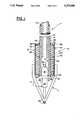
- FIG. 1is a fragmentary partial cross-sectional view and partial elevation of the sensor assembly of the present invention.
- FIG. 2is a fragmentary bottom perspective view of the sensor assembly of the present invention.
- FIG. 3is a fragmentary top perspective view of the sensor assembly of the present invention.
- Drop-in sensor assembly Dincludes handle H, weight W, cage C and sensor S.
- Handle Hincludes first pipe 12 secured within second pipe 14.
- Pipe 14is preferably a 3/4 inch schedule 80 steel pipe.
- the inner diameter of pipe 14is sized to accommodate end portion 16 of sensor S, such as Electro-Nite 6/30 thermocouple sensor, with a minimum amount of void space 18.
- Pipe 12, preferably a 3/8 inch schedule 80 steel pipeis slid or pressed into pipe 14 and secured therein. Pipes 12 and 14 are chosen to minimize any void spaces between them. Pipe 12 terminates at end 20 short of end 22 of pipe 14, leaving cavity 24.
- cavity 24is minimized, as are all void spaces in drop-in sensor assembly D, but is large enough to accommodate end portion 16 of sensor S and the connections between sensor leads 26 and the electrical cable, not shown in the figures, leading through handle H to the recording equipment.
- Pipes 12 and 14are secured, as by welding, at weld 27 opposite ends 20 and 22. Use of two pipes 12 and 14 provides protection to the electrical cable from the molten steel and also minimizes the amount of void space in handle H.
- Weight WSurrounding end 28 of handle H is weight W.
- Weight Wis positioned close to sensor S to ensure that sensor S will be submerged in the molten steel.
- Weight Wincludes high density material 30 contained within receptacle 32.
- High density material 30has a density greater than that of molten steel. In testing, it has been found that high density material 30 should have a density sufficient that the bulk density of weight W is at least 1.2 times the density of molten steel to ensure immersion of drop-in sensor assembly D to a depth sufficient to obtain an accurate reading.
- Bulk densityis used herein to mean the overall density, including both high density material 30 and any voids contained within it. Suitable materials for high density material 30 include lead and copper.
- Material 30is introduced into receptacle 32 in a molten state to fill receptacle 30 as completely as possible and leave the fewest voids as possible.
- Leadis a particularly preferred material because of its high density, low cost and low shrinkage upon solidification. Low solidification shrinkage helps minimize void spaces in receptacle 32, such as void 33, as best shown in FIG. 1.
- Receptacle 32includes tube 34 and washers 36 and 38. Washers 36 and 38 extend transversely outward of pipe 14 from outer surface 39 of pipe 14 to ends 40 and 42 of tube 34.
- tube 34is a steel tube having dimensions of 2 inch O.D. ⁇ 0.065 inch wall ⁇ 3 inch long and washers 36 and 38 are SAE flat steel washers having 2 inch O.D., 1 1/16" I.D. and a thickness of 9/64 inch. Chamber 32 as thus described will hold approximately 2.3 pounds of lead.
- Washer 36is secured, as by welding, about the circumference of pipe 14 adjacent end face 22, in a leak tight seal. Washer 36 is similarly secured to end face 40 of tube 34 in a leak tight seal. A leak tight seal is desired to prevent leakage of material 30 when poured into receptacle 32.
- Washer 38is axially spaced from washer 36 the length of tube 34. Washer 38 is secured to pipe 14 and to end face 42 of tube 34 in a manner, such as by tack welding 43, to create circumferentially spaced vents 45 while securing washer 38 to pipe 14. Washer 38 prevents material 30 from boiling off before the reading is completed. However, because lead is molten at the temperature of molten steel, vented seals 45 are desired to prevent a pressure build-up due to boiling while drop-in sensor assembly D is immersed in the bath of molten steel.
- Vented sealsprevent a catastrophic failure of drop-in sensor assembly D on account of pressure and/or volume changes, because the melting point of steel, usually in excess of 1500° C., is well above the melting point of lead, 327° C., and close to its boiling point of 1740° C.
- cage Cincludes two 1/4 inch diameter solid steel rods 44.
- Rods 44surround sensor S to provide protection to sensor S while the slag layer is being penetrated. Particular attention has been paid to allowing molten steel to permeate through cage C and between rods 44 to envelop sensor S. Rods 44 are arranged perpendicularly to each other thereby providing a cruciform configuration, which provides satisfactory protection for sensor S while allowing molten steel to immediately contact sensor S in order to provide a reading.
- each rod 44is bent into a V-shape, as best shown in FIG. 1, and secured to the outer periphery of tube 34 by welding.
- the inherently strong crossed V-shape cage Cprovides protection for sensor S as assembly D penetrates the slag layer.
- Cage Calso provides advantages over prior art cast leg designs, which are more easily broken. To increase the strength of cast legs, the cast legs must be relatively thick and heavy, thereby resulting in slower melting compared to the rods of the present invention, and inaccurate temperature readings because of the large mass of relatively cool metal surrounding the sensor during the period when the case is melting.
- the comparatively small mass rods 44 of cage Care not easily broken, and provide little cooling effect to the molten steel during the critical temperature reading. While protecting sensor S, the open design of cage C allows molten steel to quickly and completely surround and envelop sensor S to provide an accurate reading.
- sensor Sis a platinum/rhodium-platinum thermocouple.
- Sensor Smay also be an oxygen sensor.
- the thermocouple sensor as shown in FIGS. 1 and 2is an Electro-Nite 6/30.
- the Electro-Nite 6/30is a thermocouple made from one platinum wire alloyed with 6% rhodium welded to a second wire which is an alloy of 30% rhodium and 70% platinum. This thermocouple is encased in a U-shaped quartz tube the ends of which are potted with a refractory cement in a ceramic case 46.
- the Electro-Nite 6/30 thermocoupleis provided with sensor leads 26. Because of pipes 12 and 14, leads 26 have good thermal isolation during the measurement process.
- the mass of weight Wthermally isolates leads 26 and end portion 16, thereby providing a longer effective life while assuring that the temperature measured is that affecting the thermocouple.
- Sensor leads 26are connected to a two-wire electrical cable, not shown, using crimp connectors. Lead solder may be used along with crimping, but is not necessary.
- sensor Sincludes a case 46 comprising an essentially hollow essentially cylindrical-shaped first end portion 16, a centrally located thick washer-shaped ceramic flange portion, and a thimble-shaped second end portion 50.
- the thimble shaped endcomprises a thin metal shield which surrounds the U-shaped quartz tube of the Electro-Nite 6/30 thermocouple, encasing the thermocouple and protecting its fragile quartz tube until shield 50 melts just after it contacts the liquid steel.
- End portion 16fits inside pipe 14.
- Flange 48provides a surface for securing sensor S to end 22 of pipe 14.
- Flange 48also helps to keep molten steel from entering handle H and damaging the leads 26.
- Sensor Sis held in place against end face 22 by a refractory cement, such as Sauereisen No. 29.
- drop-in sensor assembly Dis typically dropped into a BOF through a chute used to charge the vessel with fluxes.
- Cage Chits and penetrates the slag layer.
- Cage Cprotects sensor S during its travel down the flux chute and also during the impact with the slag layer.
- the weight of assembly Dwould cause submersion of, at least, sensor S into the molten steel below the slag layer.
- Cage Ccomprised of crossed steel rods 44 and having an open and low mass design, is quickly melted by the molten steel, thereby allowing sensor S to be engulfed by the molten steel.
- Case 46 of sensor Sis also rapidly melted exposing the actual temperature or oxygen sensing element to the molten steel.
Landscapes
- Physics & Mathematics (AREA)
- General Physics & Mathematics (AREA)
- Investigating And Analyzing Materials By Characteristic Methods (AREA)
Abstract
Description
Claims (19)
Priority Applications (1)
| Application Number | Priority Date | Filing Date | Title |
|---|---|---|---|
| US08/068,002US5275488A (en) | 1993-05-27 | 1993-05-27 | BOF drop-in thermocouple |
Applications Claiming Priority (1)
| Application Number | Priority Date | Filing Date | Title |
|---|---|---|---|
| US08/068,002US5275488A (en) | 1993-05-27 | 1993-05-27 | BOF drop-in thermocouple |
Publications (1)
| Publication Number | Publication Date |
|---|---|
| US5275488Atrue US5275488A (en) | 1994-01-04 |
Family
ID=22079809
Family Applications (1)
| Application Number | Title | Priority Date | Filing Date |
|---|---|---|---|
| US08/068,002Expired - Fee RelatedUS5275488A (en) | 1993-05-27 | 1993-05-27 | BOF drop-in thermocouple |
Country Status (1)
| Country | Link |
|---|---|
| US (1) | US5275488A (en) |
Cited By (25)
| Publication number | Priority date | Publication date | Assignee | Title |
|---|---|---|---|---|
| WO1996026419A1 (en)* | 1995-02-24 | 1996-08-29 | Heraeus Electro-Nite International N.V. | Drop-in immersion probe |
| US5610346A (en)* | 1996-01-05 | 1997-03-11 | Bethlehem Steel Corporation | Apparatus for storing and dropping expendable BOF sensors |
| US6536949B1 (en)* | 2000-03-07 | 2003-03-25 | Richard R. Heuser | Catheter for thermal evaluation of arteriosclerotic plaque |
| US20040119211A1 (en)* | 2001-06-11 | 2004-06-24 | Robins James W. | Metal making lance assembly |
| US20040148005A1 (en)* | 2002-10-17 | 2004-07-29 | Heuser Richard R. | Stent with covering and differential dilation |
| US6830374B1 (en)* | 1999-08-16 | 2004-12-14 | Temperature Management Systems (Proprietary) Limited | Metallurgical thermocouple |
| US20060225774A1 (en)* | 2005-04-07 | 2006-10-12 | Heraeus Electro-Nite International N.V. | Sensor for Measuring the Temperature of Flowing Metals |
| RU2295420C1 (en)* | 2005-06-30 | 2007-03-20 | Общество с ограниченной ответственностью "Обнинская термоэлектрическая компания" | Metallurgical furnace thermal probe |
| US20070161956A1 (en)* | 2003-01-27 | 2007-07-12 | Heuser Richard R | Catheter introducer system |
| US20070173878A1 (en)* | 2006-01-25 | 2007-07-26 | Heuser Richard R | Catheter system for connecting adjacent blood vessels |
| US20070185567A1 (en)* | 2006-01-25 | 2007-08-09 | Heuser Richard R | Catheter system with stent device for connecting adjacent blood vessels |
| US20070203515A1 (en)* | 2006-01-25 | 2007-08-30 | Heuser Richard R | Catheter system for connecting adjacent blood vessels |
| US20070203572A1 (en)* | 2006-01-25 | 2007-08-30 | Heuser Richard R | Catheter system with stent apparatus for connecting adjacent blood vessels |
| US20070265563A1 (en)* | 2006-05-11 | 2007-11-15 | Heuser Richard R | Device for treating chronic total occlusion |
| US20080065019A1 (en)* | 2006-01-25 | 2008-03-13 | Heuser Richard R | Catheter system for connecting adjacent blood vessels |
| US20080154153A1 (en)* | 2004-08-25 | 2008-06-26 | Heuser Richard R | Multiple-wire systems and methods for ablation of occlusions within blood vessels |
| US7402141B2 (en) | 2003-08-27 | 2008-07-22 | Heuser Richard R | Catheter guidewire system using concentric wires |
| US20080177249A1 (en)* | 2007-01-22 | 2008-07-24 | Heuser Richard R | Catheter introducer system |
| US20080234813A1 (en)* | 2007-03-20 | 2008-09-25 | Heuser Richard R | Percutaneous Interventional Cardiology System for Treating Valvular Disease |
| US20090093791A1 (en)* | 1999-09-17 | 2009-04-09 | Heuser Richard R | Devices and methods for treating chronic total occlusion |
| US20090125045A1 (en)* | 2004-08-25 | 2009-05-14 | Heuser Richard R | Systems and methods for ablation of occlusions within blood vessels |
| DE102009059780A1 (en) | 2009-06-05 | 2010-12-09 | Heraeus Electro-Nite International N.V. | Throw probe |
| US20110077680A1 (en)* | 2008-01-28 | 2011-03-31 | Heuser Richard R | Large mouth snare device |
| WO2016132231A3 (en)* | 2015-02-18 | 2016-11-03 | Ardee Technologies Pvt. Ltd. | Apparatus and methods for continuous temperature measurement in molten metals |
| US20230243005A1 (en)* | 2020-07-01 | 2023-08-03 | Jfe Steel Corporation | Converter blowing control method and converter blowing control system |
Citations (27)
| Publication number | Priority date | Publication date | Assignee | Title |
|---|---|---|---|---|
| US2271254A (en)* | 1940-08-05 | 1942-01-27 | David L Dewitt | Thermometer |
| US2585404A (en)* | 1950-03-06 | 1952-02-12 | United States Steel Corp | Device for introducing solid materials into molten metals |
| GB883629A (en)* | 1958-02-03 | 1961-12-06 | Leeds & Northrup Co | An expendable immersion temperature-sensing unit |
| US3038951A (en)* | 1961-01-19 | 1962-06-12 | Leeds & Northrup Co | Fast acting totally expendable immersion thermocouple |
| US3275479A (en)* | 1963-01-15 | 1966-09-27 | Pyrotemp Corp | Pyrometric lance apparatus |
| US3288654A (en)* | 1962-06-19 | 1966-11-29 | Honeywell Inc | Disposable immersion-type thermocouple |
| US3347099A (en)* | 1965-04-27 | 1967-10-17 | Jones & Laughlin Steel Corp | Molten bath temperature measurement |
| US3374122A (en)* | 1964-12-24 | 1968-03-19 | Gen Electric | Expendable immersion thermocouple including weight |
| US3463005A (en)* | 1966-07-12 | 1969-08-26 | Leeds & Northrup Co | Immersion molten metal sampler device |
| US3493439A (en)* | 1966-02-28 | 1970-02-03 | Leeds & Northrup Co | Expendable immersion plug-in thermocouple unit |
| US3501957A (en)* | 1968-02-26 | 1970-03-24 | Leeds & Northrup Co | Expendable immersion thermocouple assembly and compensating circuit |
| US3505871A (en)* | 1968-03-21 | 1970-04-14 | Bethlehem Steel Corp | Apparatus for determining the temperature of a molten ferrous bath in a basic oxygen furnace |
| US3531331A (en)* | 1966-02-23 | 1970-09-29 | Leeds & Northrup Co | Expendable immersion temperature responsive unit and heat-sensing assembly therefor |
| US3574598A (en)* | 1967-08-18 | 1971-04-13 | Bethlehem Steel Corp | Method for controlling basic oxygen steelmaking |
| US3597975A (en)* | 1968-08-16 | 1971-08-10 | Bethlehem Steel Corp | Apparatus for introducing a drop-in thermocouple into a basic oxygen furnace |
| US3643509A (en)* | 1969-02-04 | 1972-02-22 | Hubertus Joannes Josephus Suri | Thermocouple lance |
| US3672222A (en)* | 1970-12-16 | 1972-06-27 | Bethlehem Steel Corp | Instrument lance for basic oxygen steelmaking furnace |
| US3685359A (en)* | 1967-05-11 | 1972-08-22 | Electro Nite Eng Co | Expendable lance |
| DE2207307A1 (en)* | 1972-02-17 | 1973-08-30 | Kuenzer & Co Mess Pruef Und Re | SINGLE USE TEMPERATURE MEASURING HEAD AND PROCEDURE FOR ITS MANUFACTURING |
| DE2218642A1 (en)* | 1972-04-18 | 1973-11-08 | Kuenzer & Co | SUBMERSIBLE MEASURING HEAD FOR MEASURING THE TEMPERATURE OF METAL MELT |
| US3915002A (en)* | 1974-08-16 | 1975-10-28 | Leeds & Northrup Co | Sampler for molten materials |
| US3922916A (en)* | 1974-07-15 | 1975-12-02 | Leeds & Northrup Co | Sampler for molten materials |
| US3950992A (en)* | 1975-08-27 | 1976-04-20 | Leeds & Northrup Company | Immersion sampler for molten metal |
| US4871263A (en)* | 1988-05-16 | 1989-10-03 | Pyromation, Inc. | Protective tube for a temperature sensor |
| US4881824A (en)* | 1988-12-23 | 1989-11-21 | Midwest Instrument Co., Inc. | Immersible probe |
| US4964736A (en)* | 1982-10-08 | 1990-10-23 | Electro-Nite Co. | Immersion measuring probe for use in molten metals |
| US4975123A (en)* | 1988-02-16 | 1990-12-04 | Foseco International Limited | Thermocouples with bimetallic junction on closed end and compensating conductors |
- 1993
- 1993-05-27USUS08/068,002patent/US5275488A/ennot_activeExpired - Fee Related
Patent Citations (27)
| Publication number | Priority date | Publication date | Assignee | Title |
|---|---|---|---|---|
| US2271254A (en)* | 1940-08-05 | 1942-01-27 | David L Dewitt | Thermometer |
| US2585404A (en)* | 1950-03-06 | 1952-02-12 | United States Steel Corp | Device for introducing solid materials into molten metals |
| GB883629A (en)* | 1958-02-03 | 1961-12-06 | Leeds & Northrup Co | An expendable immersion temperature-sensing unit |
| US3038951A (en)* | 1961-01-19 | 1962-06-12 | Leeds & Northrup Co | Fast acting totally expendable immersion thermocouple |
| US3288654A (en)* | 1962-06-19 | 1966-11-29 | Honeywell Inc | Disposable immersion-type thermocouple |
| US3275479A (en)* | 1963-01-15 | 1966-09-27 | Pyrotemp Corp | Pyrometric lance apparatus |
| US3374122A (en)* | 1964-12-24 | 1968-03-19 | Gen Electric | Expendable immersion thermocouple including weight |
| US3347099A (en)* | 1965-04-27 | 1967-10-17 | Jones & Laughlin Steel Corp | Molten bath temperature measurement |
| US3531331A (en)* | 1966-02-23 | 1970-09-29 | Leeds & Northrup Co | Expendable immersion temperature responsive unit and heat-sensing assembly therefor |
| US3493439A (en)* | 1966-02-28 | 1970-02-03 | Leeds & Northrup Co | Expendable immersion plug-in thermocouple unit |
| US3463005A (en)* | 1966-07-12 | 1969-08-26 | Leeds & Northrup Co | Immersion molten metal sampler device |
| US3685359A (en)* | 1967-05-11 | 1972-08-22 | Electro Nite Eng Co | Expendable lance |
| US3574598A (en)* | 1967-08-18 | 1971-04-13 | Bethlehem Steel Corp | Method for controlling basic oxygen steelmaking |
| US3501957A (en)* | 1968-02-26 | 1970-03-24 | Leeds & Northrup Co | Expendable immersion thermocouple assembly and compensating circuit |
| US3505871A (en)* | 1968-03-21 | 1970-04-14 | Bethlehem Steel Corp | Apparatus for determining the temperature of a molten ferrous bath in a basic oxygen furnace |
| US3597975A (en)* | 1968-08-16 | 1971-08-10 | Bethlehem Steel Corp | Apparatus for introducing a drop-in thermocouple into a basic oxygen furnace |
| US3643509A (en)* | 1969-02-04 | 1972-02-22 | Hubertus Joannes Josephus Suri | Thermocouple lance |
| US3672222A (en)* | 1970-12-16 | 1972-06-27 | Bethlehem Steel Corp | Instrument lance for basic oxygen steelmaking furnace |
| DE2207307A1 (en)* | 1972-02-17 | 1973-08-30 | Kuenzer & Co Mess Pruef Und Re | SINGLE USE TEMPERATURE MEASURING HEAD AND PROCEDURE FOR ITS MANUFACTURING |
| DE2218642A1 (en)* | 1972-04-18 | 1973-11-08 | Kuenzer & Co | SUBMERSIBLE MEASURING HEAD FOR MEASURING THE TEMPERATURE OF METAL MELT |
| US3922916A (en)* | 1974-07-15 | 1975-12-02 | Leeds & Northrup Co | Sampler for molten materials |
| US3915002A (en)* | 1974-08-16 | 1975-10-28 | Leeds & Northrup Co | Sampler for molten materials |
| US3950992A (en)* | 1975-08-27 | 1976-04-20 | Leeds & Northrup Company | Immersion sampler for molten metal |
| US4964736A (en)* | 1982-10-08 | 1990-10-23 | Electro-Nite Co. | Immersion measuring probe for use in molten metals |
| US4975123A (en)* | 1988-02-16 | 1990-12-04 | Foseco International Limited | Thermocouples with bimetallic junction on closed end and compensating conductors |
| US4871263A (en)* | 1988-05-16 | 1989-10-03 | Pyromation, Inc. | Protective tube for a temperature sensor |
| US4881824A (en)* | 1988-12-23 | 1989-11-21 | Midwest Instrument Co., Inc. | Immersible probe |
Cited By (37)
| Publication number | Priority date | Publication date | Assignee | Title |
|---|---|---|---|---|
| WO1996026419A1 (en)* | 1995-02-24 | 1996-08-29 | Heraeus Electro-Nite International N.V. | Drop-in immersion probe |
| AU697081B2 (en)* | 1995-02-24 | 1998-09-24 | Heraeus Electro-Nite International N.V. | Drop-in immersion probe |
| RU2164342C2 (en)* | 1995-02-24 | 2001-03-20 | Хераеус Электро-Ните Интернациональ Н.В. | Submersible downstroke probe |
| US5584578A (en)* | 1995-02-24 | 1996-12-17 | Heraeus Electro-Nite International N.V. | Drop-in immersion probe |
| US5610346A (en)* | 1996-01-05 | 1997-03-11 | Bethlehem Steel Corporation | Apparatus for storing and dropping expendable BOF sensors |
| US6830374B1 (en)* | 1999-08-16 | 2004-12-14 | Temperature Management Systems (Proprietary) Limited | Metallurgical thermocouple |
| US20090093791A1 (en)* | 1999-09-17 | 2009-04-09 | Heuser Richard R | Devices and methods for treating chronic total occlusion |
| US6536949B1 (en)* | 2000-03-07 | 2003-03-25 | Richard R. Heuser | Catheter for thermal evaluation of arteriosclerotic plaque |
| US20040119211A1 (en)* | 2001-06-11 | 2004-06-24 | Robins James W. | Metal making lance assembly |
| US20090026668A1 (en)* | 2001-06-11 | 2009-01-29 | Robins James W | Metal making lance assembly |
| US20040148005A1 (en)* | 2002-10-17 | 2004-07-29 | Heuser Richard R. | Stent with covering and differential dilation |
| US7300459B2 (en) | 2002-10-17 | 2007-11-27 | Heuser Richard R | Stent with covering and differential dilation |
| US7914492B2 (en) | 2003-01-27 | 2011-03-29 | Heuser Richard R | Catheter introducer system |
| US20070161956A1 (en)* | 2003-01-27 | 2007-07-12 | Heuser Richard R | Catheter introducer system |
| US7402141B2 (en) | 2003-08-27 | 2008-07-22 | Heuser Richard R | Catheter guidewire system using concentric wires |
| US20090125045A1 (en)* | 2004-08-25 | 2009-05-14 | Heuser Richard R | Systems and methods for ablation of occlusions within blood vessels |
| US20080154153A1 (en)* | 2004-08-25 | 2008-06-26 | Heuser Richard R | Multiple-wire systems and methods for ablation of occlusions within blood vessels |
| US8545418B2 (en) | 2004-08-25 | 2013-10-01 | Richard R. Heuser | Systems and methods for ablation of occlusions within blood vessels |
| US7772483B2 (en)* | 2005-04-07 | 2010-08-10 | Heraeus Electro-Nite International N.V. | Sensor for measuring the temperature of flowing metals |
| US20060225774A1 (en)* | 2005-04-07 | 2006-10-12 | Heraeus Electro-Nite International N.V. | Sensor for Measuring the Temperature of Flowing Metals |
| RU2295420C1 (en)* | 2005-06-30 | 2007-03-20 | Общество с ограниченной ответственностью "Обнинская термоэлектрическая компания" | Metallurgical furnace thermal probe |
| US8062321B2 (en) | 2006-01-25 | 2011-11-22 | Pq Bypass, Inc. | Catheter system for connecting adjacent blood vessels |
| US20080065019A1 (en)* | 2006-01-25 | 2008-03-13 | Heuser Richard R | Catheter system for connecting adjacent blood vessels |
| US7374567B2 (en) | 2006-01-25 | 2008-05-20 | Heuser Richard R | Catheter system for connecting adjacent blood vessels |
| US20070203572A1 (en)* | 2006-01-25 | 2007-08-30 | Heuser Richard R | Catheter system with stent apparatus for connecting adjacent blood vessels |
| US20070203515A1 (en)* | 2006-01-25 | 2007-08-30 | Heuser Richard R | Catheter system for connecting adjacent blood vessels |
| US20070185567A1 (en)* | 2006-01-25 | 2007-08-09 | Heuser Richard R | Catheter system with stent device for connecting adjacent blood vessels |
| US20070173878A1 (en)* | 2006-01-25 | 2007-07-26 | Heuser Richard R | Catheter system for connecting adjacent blood vessels |
| US20070265563A1 (en)* | 2006-05-11 | 2007-11-15 | Heuser Richard R | Device for treating chronic total occlusion |
| US20080177249A1 (en)* | 2007-01-22 | 2008-07-24 | Heuser Richard R | Catheter introducer system |
| US20080234813A1 (en)* | 2007-03-20 | 2008-09-25 | Heuser Richard R | Percutaneous Interventional Cardiology System for Treating Valvular Disease |
| US20110197900A1 (en)* | 2007-03-20 | 2011-08-18 | Heuser Richard R | Percutaneous interventional cardiology system for treating valvular disease |
| US20110077680A1 (en)* | 2008-01-28 | 2011-03-31 | Heuser Richard R | Large mouth snare device |
| DE102009059780A1 (en) | 2009-06-05 | 2010-12-09 | Heraeus Electro-Nite International N.V. | Throw probe |
| US9116054B2 (en) | 2009-06-05 | 2015-08-25 | Heraeus Electro-Nite International N.V. | Drop-in probe |
| WO2016132231A3 (en)* | 2015-02-18 | 2016-11-03 | Ardee Technologies Pvt. Ltd. | Apparatus and methods for continuous temperature measurement in molten metals |
| US20230243005A1 (en)* | 2020-07-01 | 2023-08-03 | Jfe Steel Corporation | Converter blowing control method and converter blowing control system |
Similar Documents
| Publication | Publication Date | Title |
|---|---|---|
| US5275488A (en) | BOF drop-in thermocouple | |
| KR100385828B1 (en) | Falling Input Probe | |
| US3357250A (en) | Temperature detector and sampling device | |
| US3463005A (en) | Immersion molten metal sampler device | |
| US5520461A (en) | Airtight thermocouple probe | |
| US4964736A (en) | Immersion measuring probe for use in molten metals | |
| US6102565A (en) | Ceramic sheath type thermocouple | |
| EP0887632A1 (en) | A ceramic thermocouple for measuring temperature of molten metal | |
| US3758397A (en) | Apparatus for oxygen determination | |
| US5180228A (en) | Radiation thermometer for molten iron and method for measuring the temperature of molten iron | |
| US3374122A (en) | Expendable immersion thermocouple including weight | |
| US3950992A (en) | Immersion sampler for molten metal | |
| US3647559A (en) | Measuring device for continuously measuring the temperature of metal baths | |
| US4007106A (en) | Device for measuring oxygen concentration in molten-metal | |
| US3922916A (en) | Sampler for molten materials | |
| US5917145A (en) | Method and apparatus for measurement of temperatures of molten aluminum and aluminum alloys | |
| US3577886A (en) | Device for immersion in molten material to sample and/or measure temperature | |
| US9958405B2 (en) | Reverse filling carbon and temperature drop-in sensor | |
| US3201277A (en) | Immersion thermocouple | |
| GB2196430A (en) | Probe for measuring in molten metal | |
| EP0045535A2 (en) | Immersion measuring probe for use in liquid metals | |
| US3508976A (en) | Throw-in thermocouple for basic oxygen furnace | |
| JP2002188965A (en) | thermocouple | |
| SK278087B6 (en) | Submersible measuring probe | |
| JPH0315729A (en) | Temperature measuring device for molten metal |
Legal Events
| Date | Code | Title | Description |
|---|---|---|---|
| AS | Assignment | Owner name:BETHLEHEM STEEL CORPORATION, PENNSYLVANIA Free format text:ASSIGNMENT OF ASSIGNORS INTEREST;ASSIGNOR:STELTS, PHILIP D.;REEL/FRAME:006571/0715 Effective date:19930521 | |
| REMI | Maintenance fee reminder mailed | ||
| FPAY | Fee payment | Year of fee payment:4 | |
| SULP | Surcharge for late payment | ||
| FPAY | Fee payment | Year of fee payment:8 | |
| AS | Assignment | Owner name:ISG TECHNOLOGIES, INC., OHIO Free format text:ASSIGNMENT OF ASSIGNORS INTEREST;ASSIGNOR:BETHLEHEM STEEL CORPORATION;REEL/FRAME:014033/0881 Effective date:20030506 | |
| AS | Assignment | Owner name:CIT GROUP/BUSINESS CREDIT, INC., AS COLLATERAL AGE Free format text:PLEDGE AND SECURITY AGREEMENT;ASSIGNOR:INTERNATIONAL STEEL GROUP, INC.;REEL/FRAME:013663/0415 Effective date:20030507 | |
| REMI | Maintenance fee reminder mailed | ||
| LAPS | Lapse for failure to pay maintenance fees | ||
| STCH | Information on status: patent discontinuation | Free format text:PATENT EXPIRED DUE TO NONPAYMENT OF MAINTENANCE FEES UNDER 37 CFR 1.362 | |
| FP | Lapsed due to failure to pay maintenance fee | Effective date:20060104 | |
| AS | Assignment | Owner name:ISG SOUTH CHICAGO & INDIANA HARBOR RAILWAY COMPANY Free format text:RELEASE BY SECURED PARTY;ASSIGNOR:THE CIT GROUP/BUSINESS CREDIT, INC., AS COLLATERAL AGENT;REEL/FRAME:019432/0170 Effective date:20070613 Owner name:ISG BURNS HARBOR INC., OHIO Free format text:RELEASE BY SECURED PARTY;ASSIGNOR:THE CIT GROUP/BUSINESS CREDIT, INC., AS COLLATERAL AGENT;REEL/FRAME:019432/0170 Effective date:20070613 Owner name:ISG PIEDMONT INC., OHIO Free format text:RELEASE BY SECURED PARTY;ASSIGNOR:THE CIT GROUP/BUSINESS CREDIT, INC., AS COLLATERAL AGENT;REEL/FRAME:019432/0170 Effective date:20070613 Owner name:ISG LACKAWANNA INC., OHIO Free format text:RELEASE BY SECURED PARTY;ASSIGNOR:THE CIT GROUP/BUSINESS CREDIT, INC., AS COLLATERAL AGENT;REEL/FRAME:019432/0170 Effective date:20070613 Owner name:ISG PLATE INC., OHIO Free format text:RELEASE BY SECURED PARTY;ASSIGNOR:THE CIT GROUP/BUSINESS CREDIT, INC., AS COLLATERAL AGENT;REEL/FRAME:019432/0170 Effective date:20070613 Owner name:ISG WARREN INC., OHIO Free format text:RELEASE BY SECURED PARTY;ASSIGNOR:THE CIT GROUP/BUSINESS CREDIT, INC., AS COLLATERAL AGENT;REEL/FRAME:019432/0170 Effective date:20070613 Owner name:ISG/EGL HOLDING COMPANY, OHIO Free format text:RELEASE BY SECURED PARTY;ASSIGNOR:THE CIT GROUP/BUSINESS CREDIT, INC., AS COLLATERAL AGENT;REEL/FRAME:019432/0170 Effective date:20070613 Owner name:ISG HENNEPIN, INC., OHIO Free format text:RELEASE BY SECURED PARTY;ASSIGNOR:THE CIT GROUP/BUSINESS CREDIT, INC., AS COLLATERAL AGENT;REEL/FRAME:019432/0170 Effective date:20070613 Owner name:ISG HIBBING, INC., OHIO Free format text:RELEASE BY SECURED PARTY;ASSIGNOR:THE CIT GROUP/BUSINESS CREDIT, INC., AS COLLATERAL AGENT;REEL/FRAME:019432/0170 Effective date:20070613 Owner name:ISG SPARROWS POINT INC., OHIO Free format text:RELEASE BY SECURED PARTY;ASSIGNOR:THE CIT GROUP/BUSINESS CREDIT, INC., AS COLLATERAL AGENT;REEL/FRAME:019432/0170 Effective date:20070613 Owner name:ISG CLEVELAND WEST, INC., OHIO Free format text:RELEASE BY SECURED PARTY;ASSIGNOR:THE CIT GROUP/BUSINESS CREDIT, INC., AS COLLATERAL AGENT;REEL/FRAME:019432/0170 Effective date:20070613 Owner name:INTERNATIONAL STEEL GROUP, INC., OHIO Free format text:RELEASE BY SECURED PARTY;ASSIGNOR:THE CIT GROUP/BUSINESS CREDIT, INC., AS COLLATERAL AGENT;REEL/FRAME:019432/0170 Effective date:20070613 Owner name:ISG RAILWAYS, INC., OHIO Free format text:RELEASE BY SECURED PARTY;ASSIGNOR:THE CIT GROUP/BUSINESS CREDIT, INC., AS COLLATERAL AGENT;REEL/FRAME:019432/0170 Effective date:20070613 Owner name:ISG VENTURE, INC., OHIO Free format text:RELEASE BY SECURED PARTY;ASSIGNOR:THE CIT GROUP/BUSINESS CREDIT, INC., AS COLLATERAL AGENT;REEL/FRAME:019432/0170 Effective date:20070613 Owner name:ISG RIVERDALE INC., OHIO Free format text:RELEASE BY SECURED PARTY;ASSIGNOR:THE CIT GROUP/BUSINESS CREDIT, INC., AS COLLATERAL AGENT;REEL/FRAME:019432/0170 Effective date:20070613 Owner name:ISG INDIANA HARBOR INC., OHIO Free format text:RELEASE BY SECURED PARTY;ASSIGNOR:THE CIT GROUP/BUSINESS CREDIT, INC., AS COLLATERAL AGENT;REEL/FRAME:019432/0170 Effective date:20070613 Owner name:ISG CLEVELAND WEST PROPERTIES, INC., OHIO Free format text:RELEASE BY SECURED PARTY;ASSIGNOR:THE CIT GROUP/BUSINESS CREDIT, INC., AS COLLATERAL AGENT;REEL/FRAME:019432/0170 Effective date:20070613 Owner name:ISG CLEVELAND INC., OHIO Free format text:RELEASE BY SECURED PARTY;ASSIGNOR:THE CIT GROUP/BUSINESS CREDIT, INC., AS COLLATERAL AGENT;REEL/FRAME:019432/0170 Effective date:20070613 Owner name:ISG ACQUISITION INC., OHIO Free format text:RELEASE BY SECURED PARTY;ASSIGNOR:THE CIT GROUP/BUSINESS CREDIT, INC., AS COLLATERAL AGENT;REEL/FRAME:019432/0170 Effective date:20070613 Owner name:ISG CLEVELAND WORKS RAILWAY COMPANY, OHIO Free format text:RELEASE BY SECURED PARTY;ASSIGNOR:THE CIT GROUP/BUSINESS CREDIT, INC., AS COLLATERAL AGENT;REEL/FRAME:019432/0170 Effective date:20070613 Owner name:ISG TECHNOLOGIES, INC., OHIO Free format text:RELEASE BY SECURED PARTY;ASSIGNOR:THE CIT GROUP/BUSINESS CREDIT, INC., AS COLLATERAL AGENT;REEL/FRAME:019432/0170 Effective date:20070613 Owner name:ISG SALES, INC., OHIO Free format text:RELEASE BY SECURED PARTY;ASSIGNOR:THE CIT GROUP/BUSINESS CREDIT, INC., AS COLLATERAL AGENT;REEL/FRAME:019432/0170 Effective date:20070613 Owner name:ISG STEELTON INC., OHIO Free format text:RELEASE BY SECURED PARTY;ASSIGNOR:THE CIT GROUP/BUSINESS CREDIT, INC., AS COLLATERAL AGENT;REEL/FRAME:019432/0170 Effective date:20070613 Owner name:BETHLEHEM HIBBING CORPORATION, OHIO Free format text:RELEASE BY SECURED PARTY;ASSIGNOR:THE CIT GROUP/BUSINESS CREDIT, INC., AS COLLATERAL AGENT;REEL/FRAME:019432/0170 Effective date:20070613 |