US5275151A - Handle for deflectable catheter - Google Patents
Handle for deflectable catheterDownload PDFInfo
- Publication number
- US5275151A US5275151AUS07/804,933US80493391AUS5275151AUS 5275151 AUS5275151 AUS 5275151AUS 80493391 AUS80493391 AUS 80493391AUS 5275151 AUS5275151 AUS 5275151A
- Authority
- US
- United States
- Prior art keywords
- body member
- handle device
- endoscope
- bore
- distal end
- Prior art date
- Legal status (The legal status is an assumption and is not a legal conclusion. Google has not performed a legal analysis and makes no representation as to the accuracy of the status listed.)
- Expired - Lifetime
Links
- 238000011010flushing procedureMethods0.000claimsabstractdescription13
- 239000007788liquidSubstances0.000claimsabstractdescription10
- 239000000835fiberSubstances0.000claimsdescription21
- 239000004033plasticSubstances0.000claimsdescription8
- 238000007789sealingMethods0.000claimsdescription6
- 239000012530fluidSubstances0.000claimsdescription5
- 238000006073displacement reactionMethods0.000claimsdescription3
- 230000008878couplingEffects0.000claims1
- 238000010168coupling processMethods0.000claims1
- 238000005859coupling reactionMethods0.000claims1
- 230000000881depressing effectEffects0.000abstractdescription2
- 239000013307optical fiberSubstances0.000description11
- 210000003813thumbAnatomy0.000description8
- 229910001220stainless steelInorganic materials0.000description5
- 239000010935stainless steelSubstances0.000description5
- 238000000034methodMethods0.000description4
- 230000002093peripheral effectEffects0.000description4
- 238000004519manufacturing processMethods0.000description3
- 238000000465mouldingMethods0.000description3
- FAPWRFPIFSIZLT-UHFFFAOYSA-MSodium chlorideChemical compound[Na+].[Cl-]FAPWRFPIFSIZLT-UHFFFAOYSA-M0.000description2
- 238000005520cutting processMethods0.000description2
- 230000007246mechanismEffects0.000description2
- 239000011780sodium chlorideSubstances0.000description2
- 238000001356surgical procedureMethods0.000description2
- 208000003618Intervertebral Disc DisplacementDiseases0.000description1
- 239000004793PolystyreneSubstances0.000description1
- 239000000853adhesiveSubstances0.000description1
- 230000001070adhesive effectEffects0.000description1
- 238000013459approachMethods0.000description1
- 238000005452bendingMethods0.000description1
- 230000009286beneficial effectEffects0.000description1
- 238000004891communicationMethods0.000description1
- 239000004020conductorSubstances0.000description1
- 238000010276constructionMethods0.000description1
- 230000000694effectsEffects0.000description1
- 210000003811fingerAnatomy0.000description1
- 210000005224forefingerAnatomy0.000description1
- 238000005286illuminationMethods0.000description1
- 230000013011matingEffects0.000description1
- 238000002324minimally invasive surgeryMethods0.000description1
- 238000012986modificationMethods0.000description1
- 230000004048modificationEffects0.000description1
- 239000002991molded plasticSubstances0.000description1
- 238000011017operating methodMethods0.000description1
- 230000003287optical effectEffects0.000description1
- 210000000056organAnatomy0.000description1
- 239000004417polycarbonateSubstances0.000description1
- 229920000515polycarbonatePolymers0.000description1
- 229920002223polystyrenePolymers0.000description1
- 230000003014reinforcing effectEffects0.000description1
- 125000006850spacer groupChemical group0.000description1
- 238000009987spinningMethods0.000description1
- 210000001835visceraAnatomy0.000description1
Images


Classifications
- A—HUMAN NECESSITIES
- A61—MEDICAL OR VETERINARY SCIENCE; HYGIENE
- A61M—DEVICES FOR INTRODUCING MEDIA INTO, OR ONTO, THE BODY; DEVICES FOR TRANSDUCING BODY MEDIA OR FOR TAKING MEDIA FROM THE BODY; DEVICES FOR PRODUCING OR ENDING SLEEP OR STUPOR
- A61M25/00—Catheters; Hollow probes
- A61M25/01—Introducing, guiding, advancing, emplacing or holding catheters
- A61M25/0105—Steering means as part of the catheter or advancing means; Markers for positioning
- A61M25/0133—Tip steering devices
- A61M25/0136—Handles therefor
Definitions
- the endoscopebe provided with a handle at its proximal end where the handle includes the necessary controls for not only steering the distal tip of the endoscope, but also for controlling the longitudinal displacement of the surgical instrument contained within the working lumen of the endoscope.
- handleincludes the necessary controls for not only steering the distal tip of the endoscope, but also for controlling the longitudinal displacement of the surgical instrument contained within the working lumen of the endoscope.
- prior art handles incorporating such controlshave tended to be quite complex and expensive to manufacture making it cost-prohibitive to dispose of the endoscope after only a single use.
- the prior art endoscopeshad to be designed to permit them to be cleaned and sterilized between uses with different patients.
- Another object of the inventionis to provide an improved handle for an endoscope which includes convenient controls for allowing the surgeon to steer the distal end of the endoscope and to control the movement of surgical instruments within the working lumen of the endoscope.
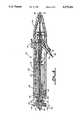
- FIG. 6is a longitudinal cross-sectional view of an alternative embodiment of a handle for an endoscope.
- a tube 46may be joined by an appropriate fitting 48 to a source of flush liquid which is made to flow through the tube 46 and down the working lumen 30 of the endoscope sheath 12.
- Connector 50is adapted to be coupled to a light source whereby light may be transmitted through optical fibers contained within the outer sheath 52 and then through the lumens 24 and 26 to the distal end 16 of the endoscope. The image information is transmitted back through lumen 28 and via cable 54 to an appropriate device for displaying the scene illuminated by the light source.
- the laser fiber 32is adapted to be coupled to a laser generator by a coupler 56. It passes through a tubular jacket 58 into the handle 36, via a bore formed through the knob 42. The laser fiber 32 in jacket 58 is appropriately routed through the handle and thence down the working lumen 30 of the endoscope sheath 12.
- a distal end cap 66is fitted onto the distal end of the body halves 60 and 62.
- the distal end cap 66tapers in both the vertical and horizontal direction to form a distal nose portion 68 having a central opening 70 formed therethrough for receiving the endoscope tube 12 therein.
- the element 126includes a tubular distal portion 128 fitted through the end cap 64 and into the bore 124.
- the integrally formed proximal segment 130 of element 126includes a counterbore 132 forming a chamber for an elastomeric valve member 134.
- the proximal end portion of the member 130includes a threaded surface 136 which is intended to mate with a molded plastic end cap 138.
Landscapes
- Health & Medical Sciences (AREA)
- Life Sciences & Earth Sciences (AREA)
- Biophysics (AREA)
- Pulmonology (AREA)
- Engineering & Computer Science (AREA)
- Anesthesiology (AREA)
- Biomedical Technology (AREA)
- Heart & Thoracic Surgery (AREA)
- Hematology (AREA)
- Animal Behavior & Ethology (AREA)
- General Health & Medical Sciences (AREA)
- Public Health (AREA)
- Veterinary Medicine (AREA)
- Endoscopes (AREA)
Abstract
Description
Claims (24)
Priority Applications (1)
| Application Number | Priority Date | Filing Date | Title |
|---|---|---|---|
| US07/804,933US5275151A (en) | 1991-12-11 | 1991-12-11 | Handle for deflectable catheter |
Applications Claiming Priority (1)
| Application Number | Priority Date | Filing Date | Title |
|---|---|---|---|
| US07/804,933US5275151A (en) | 1991-12-11 | 1991-12-11 | Handle for deflectable catheter |
Publications (1)
| Publication Number | Publication Date |
|---|---|
| US5275151Atrue US5275151A (en) | 1994-01-04 |
Family
ID=25190257
Family Applications (1)
| Application Number | Title | Priority Date | Filing Date |
|---|---|---|---|
| US07/804,933Expired - LifetimeUS5275151A (en) | 1991-12-11 | 1991-12-11 | Handle for deflectable catheter |
Country Status (1)
| Country | Link |
|---|---|
| US (1) | US5275151A (en) |
Cited By (162)
| Publication number | Priority date | Publication date | Assignee | Title |
|---|---|---|---|---|
| US5342299A (en)* | 1992-07-06 | 1994-08-30 | Catheter Imaging Systems | Steerable catheter |
| US5395329A (en)* | 1994-01-19 | 1995-03-07 | Daig Corporation | Control handle for steerable catheter |
| US5397321A (en)* | 1993-07-30 | 1995-03-14 | Ep Technologies, Inc. | Variable curve electrophysiology catheter |
| US5415158A (en)* | 1993-06-11 | 1995-05-16 | Clarus Medical Systems, Inc. | Flexible endoscope with force limiting spring coupler |
| US5454807A (en)* | 1993-05-14 | 1995-10-03 | Boston Scientific Corporation | Medical treatment of deeply seated tissue using optical radiation |
| US5458608A (en)* | 1993-06-03 | 1995-10-17 | Surgin Surgical Instrumentation Inc. | Laparoscopic instruments and methods |
| US5487757A (en)* | 1993-07-20 | 1996-01-30 | Medtronic Cardiorhythm | Multicurve deflectable catheter |
| US5514128A (en)* | 1992-08-18 | 1996-05-07 | Spectranetics Corporation | Fiber optic guide wire and support catheter therefor |
| FR2727024A1 (en)* | 1994-11-23 | 1996-05-24 | Uresil Corp | BLOCKING CATHETER SYSTEM |
| US5527279A (en)* | 1992-12-01 | 1996-06-18 | Cardiac Pathways Corporation | Control mechanism and system and method for steering distal extremity of a flexible elongate member |
| US5545200A (en)* | 1993-07-20 | 1996-08-13 | Medtronic Cardiorhythm | Steerable electrophysiology catheter |
| US5656030A (en)* | 1995-05-22 | 1997-08-12 | Boston Scientific Corporation | Bidirectional steerable catheter with deflectable distal tip |
| US5676635A (en)* | 1995-08-30 | 1997-10-14 | Levin; Bruce | Instrument for insertion of an endotracheal tube |
| US5730724A (en)* | 1995-11-24 | 1998-03-24 | Manan Medical Products, Inc. | Drainage catheter apparatus |
| USD398986S (en) | 1996-01-16 | 1998-09-29 | Catheter Imaging Systems, Inc. | Handle interface for steerable catheter |
| US5833604A (en)* | 1993-07-30 | 1998-11-10 | E.P. Technologies, Inc. | Variable stiffness electrophysiology catheter |
| US5846221A (en) | 1996-02-09 | 1998-12-08 | Catheter Imaging Systems, Inc. | Steerable catheter having disposable module and sterilizable handle and method of connecting same |
| US5857996A (en) | 1992-07-06 | 1999-01-12 | Catheter Imaging Systems | Method of epidermal surgery |
| USD405881S (en) | 1996-01-16 | 1999-02-16 | Catheter Imaging Systems, Inc. | Handle for steerable catheter |
| WO1999016355A1 (en)* | 1997-09-30 | 1999-04-08 | Boston Scientific Corporation | Drainage catheter anchor locking mechanisms |
| US5938616A (en)* | 1997-01-31 | 1999-08-17 | Acuson Corporation | Steering mechanism and steering line for a catheter-mounted ultrasonic transducer |
| US5944689A (en)* | 1993-07-30 | 1999-08-31 | E.P. Technologies, Inc. | Variable curve electrophysiology catheter |
| US5954716A (en)* | 1997-02-19 | 1999-09-21 | Oratec Interventions, Inc | Method for modifying the length of a ligament |
| US5954654A (en)* | 1997-01-31 | 1999-09-21 | Acuson Corporation | Steering mechanism and steering line for a catheter-mounted ultrasonic transducer |
| US5976075A (en)* | 1997-12-15 | 1999-11-02 | University Of Massachusetts | Endoscope deployment apparatus |
| US5980504A (en)* | 1996-08-13 | 1999-11-09 | Oratec Interventions, Inc. | Method for manipulating tissue of an intervertebral disc |
| US5987344A (en)* | 1996-08-08 | 1999-11-16 | Medtronic, Inc. | Handle for catheter assembly with multifunction wire |
| US6004320A (en)* | 1997-09-19 | 1999-12-21 | Oratec Interventions, Inc. | Clip on electrocauterizing sheath for orthopedic shave devices |
| US6007531A (en) | 1995-11-21 | 1999-12-28 | Catheter Imaging Systems, Inc. | Steerable catheter having disposable module and sterilizable handle and method of connecting same |
| US6007570A (en)* | 1996-08-13 | 1999-12-28 | Oratec Interventions, Inc. | Apparatus with functional element for performing function upon intervertebral discs |
| US6007533A (en)* | 1997-09-19 | 1999-12-28 | Oratec Interventions, Inc. | Electrocauterizing tip for orthopedic shave devices |
| US6068628A (en)* | 1996-08-20 | 2000-05-30 | Oratec Interventions, Inc. | Apparatus for treating chondromalacia |
| US6071273A (en)* | 1988-02-29 | 2000-06-06 | Scimed Life Systems, Inc. | Fixed wire dilatation balloon catheter |
| US6099514A (en)* | 1996-08-13 | 2000-08-08 | Oratec Interventions, Inc. | Method and apparatus for delivering or removing material from the interior of an intervertebral disc |
| US6135999A (en)* | 1997-02-12 | 2000-10-24 | Oratec Internationals, Inc. | Concave probe for arthroscopic surgery |
| US6168593B1 (en) | 1997-02-12 | 2001-01-02 | Oratec Interventions, Inc. | Electrode for electrosurgical coagulation of tissue |
| US6176857B1 (en) | 1997-10-22 | 2001-01-23 | Oratec Interventions, Inc. | Method and apparatus for applying thermal energy to tissue asymmetrically |
| US6200311B1 (en) | 1998-01-20 | 2001-03-13 | Eclipse Surgical Technologies, Inc. | Minimally invasive TMR device |
| US6214001B1 (en) | 1997-09-19 | 2001-04-10 | Oratec Interventions, Inc. | Electrocauterizing tool for orthopedic shave devices |
| US6231571B1 (en)* | 1999-05-03 | 2001-05-15 | Alan G. Ellman | Electrosurgical handpiece for treating tissue |
| US6283960B1 (en) | 1995-10-24 | 2001-09-04 | Oratec Interventions, Inc. | Apparatus for delivery of energy to a surgical site |
| USD455210S1 (en) | 1997-01-31 | 2002-04-02 | Acuson Corporation | Ultrasonic transducer assembly controller |
| US6450948B1 (en) | 1999-11-02 | 2002-09-17 | Vista Medical Technologies, Inc. | Deflecting tip for surgical cannula |
| US6461353B1 (en) | 1995-02-17 | 2002-10-08 | Oratec Interventions, Inc. | Orthopedic apparatus for controlled contraction of collagen tissue |
| US6464645B1 (en) | 1997-01-31 | 2002-10-15 | Acuson Corporation | Ultrasonic transducer assembly controller |
| USD465024S1 (en) | 1998-01-31 | 2002-10-29 | Acuson Corporation | Ultrasonic transducer assembly controller |
| US20020165535A1 (en)* | 2000-05-16 | 2002-11-07 | Lesh Michael D. | Deflectable tip catheter with guidewire tracking mechanism |
| US6482204B1 (en) | 1994-05-06 | 2002-11-19 | Oratec Interventions, Inc | Method and apparatus for controlled contraction of soft tissue |
| WO2002089891A3 (en)* | 2001-05-04 | 2003-03-20 | Cardiac Pacemakers Inc | Self-locking handle for steering a single or multiple-profile catheter |
| US6599296B1 (en)* | 2001-07-27 | 2003-07-29 | Advanced Cardiovascular Systems, Inc. | Ratcheting handle for intraluminal catheter systems |
| US6605033B1 (en)* | 1999-06-21 | 2003-08-12 | Pentax Corporation | Endoscope |
| US20030163085A1 (en)* | 2002-01-16 | 2003-08-28 | Tanner Howard M. | Catheter hand-piece apparatus and method of using the same |
| USD480807S1 (en) | 2002-09-06 | 2003-10-14 | C. R. Bard, Inc. | Control handle for a medical device used with an endoscope |
| US20030195577A1 (en)* | 2001-10-23 | 2003-10-16 | Pigott John D. | Steerable catheter and method for locating coronary sinus |
| US6638276B2 (en) | 2001-06-06 | 2003-10-28 | Oratec Interventions, Inc. | Intervertebral disc device employing prebent sheath |
| US6645203B2 (en) | 1997-02-12 | 2003-11-11 | Oratec Interventions, Inc. | Surgical instrument with off-axis electrode |
| US6673060B1 (en) | 2000-04-25 | 2004-01-06 | Manan Medical Products, Inc. | Drainage catheter and method for forming same |
| US20040024413A1 (en)* | 2002-07-31 | 2004-02-05 | Lentz David J. | Wire reinforced articulation segment |
| US20040030330A1 (en)* | 2002-04-18 | 2004-02-12 | Brassell James L. | Electrosurgery systems |
| US6695839B2 (en) | 2001-02-08 | 2004-02-24 | Oratec Interventions, Inc. | Method and apparatus for treatment of disrupted articular cartilage |
| US6726685B2 (en) | 2001-06-06 | 2004-04-27 | Oratec Interventions, Inc. | Intervertebral disc device employing looped probe |
| US6733496B2 (en) | 2001-06-06 | 2004-05-11 | Oratec Interventions, Inc. | Intervertebral disc device employing flexible probe |
| US6746412B1 (en)* | 1999-09-22 | 2004-06-08 | St. Jude Medical Ab | Device for manipulating a stylet unit |
| US6749605B2 (en) | 1996-10-23 | 2004-06-15 | Oratec Interventions, Inc. | Catheter for delivery of energy to a surgical site |
| US20040127963A1 (en)* | 1999-01-25 | 2004-07-01 | Uchida Andy H. | Intervertebral decompression |
| US20040215058A1 (en)* | 2002-09-06 | 2004-10-28 | Zirps Christopher T | Endoscopic accessory mounting adaptor |
| US20040220612A1 (en)* | 2003-04-30 | 2004-11-04 | Swainston Kyle W | Slidable capture catheter |
| US20040220449A1 (en)* | 2002-09-06 | 2004-11-04 | Zirps Christopher T. | External endoscopic accessory control system |
| US6832997B2 (en) | 2001-06-06 | 2004-12-21 | Oratec Interventions, Inc. | Electromagnetic energy delivery intervertebral disc treatment devices |
| US20050004515A1 (en)* | 2002-11-15 | 2005-01-06 | Hart Charles C. | Steerable kink resistant sheath |
| US20050070820A1 (en)* | 2003-09-30 | 2005-03-31 | Scimed Life Systems, Inc. | Side loading wire torquing device |
| US6878155B2 (en) | 2000-02-25 | 2005-04-12 | Oratec Interventions, Inc. | Method of treating intervertebral disc tissue employing attachment mechanism |
| US20050085848A1 (en)* | 2003-09-12 | 2005-04-21 | Johnson Steven W. | Actuating constraining mechanism |
| US20050096692A1 (en)* | 2003-09-12 | 2005-05-05 | Linder Richard J. | Methods, systems, and devices for providing embolic protection and removing embolic material |
| US20050149104A1 (en)* | 2003-10-03 | 2005-07-07 | Leeflang Stephen A. | Expandable guide sheath and apparatus and methods for making them |
| US20050159798A1 (en)* | 2003-11-07 | 2005-07-21 | Rainer Graumann | Method and apparatus for cardiac ablation |
| US20050187599A1 (en)* | 1994-05-06 | 2005-08-25 | Hugh Sharkey | Method and apparatus for controlled contraction of soft tissue |
| US20050245863A1 (en)* | 2001-12-31 | 2005-11-03 | Biosense Webster, Inc. | Dual-function catheter handle |
| US20050256452A1 (en)* | 2002-11-15 | 2005-11-17 | Demarchi Thomas | Steerable vascular sheath |
| US20050256375A1 (en)* | 2004-05-13 | 2005-11-17 | Scimed Life Systems, Inc. | Handle for steerable catheter |
| US6981945B1 (en) | 2004-11-12 | 2006-01-03 | Artann Laboratories, Inc. | Colonoscope handgrip with force and torque monitor |
| US20060047245A1 (en)* | 2004-08-24 | 2006-03-02 | Ruchir Sehra | Catheter control unit |
| US20060064054A1 (en)* | 2002-11-15 | 2006-03-23 | Applied Medical Resources Corporation | Longitudinal sheath enforcement |
| WO2006092014A1 (en)* | 2005-03-04 | 2006-09-08 | Cathrx Ltd | A catheter handle and a catheter assembly including such a handle |
| US20060217755A1 (en)* | 2004-10-04 | 2006-09-28 | Eversull Christian S | Expandable guide sheath with steerable backbone and methods for making and using them |
| US7150747B1 (en) | 2003-01-22 | 2006-12-19 | Smith & Nephew, Inc. | Electrosurgical cutter |
| US7189247B1 (en) | 2002-09-06 | 2007-03-13 | Conmed Endoscopic Technologies, Inc. | Endoscopic band ligator |
| US20070083187A1 (en)* | 2005-08-16 | 2007-04-12 | Eversull Christian S | Apparatus and methods for delivering stem cells and other agents into cardiac tissue |
| US20070167930A1 (en)* | 2005-11-23 | 2007-07-19 | Eversull Christian S | Slittable and Peelable Sheaths and Methods for Making and Using Them |
| US20070215268A1 (en)* | 2002-11-15 | 2007-09-20 | Applied Medical Resources Corporation | Method of making medical tubing having variable characteristics using thermal winding |
| US20070260225A1 (en)* | 2002-11-15 | 2007-11-08 | Applied Medical Resources Corporation | Steerable sheath actuator |
| US20070270640A1 (en)* | 2006-05-17 | 2007-11-22 | John Dimitriou | Endoscope tool coupling |
| US20070299437A1 (en)* | 2006-06-23 | 2007-12-27 | Podmore Jonathan L | Device for ablation and visualization |
| US20080015558A1 (en)* | 2006-04-04 | 2008-01-17 | The Spectranetics Corporation | Laser-assisted guidewire having a variable stiffness shaft |
| US20080015625A1 (en)* | 2004-10-04 | 2008-01-17 | Acumen Medical, Inc. | Shapeable for steerable guide sheaths and methods for making and using them |
| US20090024133A1 (en)* | 2007-07-16 | 2009-01-22 | Fionan Keady | Delivery device |
| US20090054890A1 (en)* | 2007-08-23 | 2009-02-26 | Decarlo Arnold V | Electrosurgical device with LED adapter |
| US7497853B2 (en) | 2005-05-05 | 2009-03-03 | Enpath Medical Inc. | Deflectable catheter steering and locking system |
| US20090125001A1 (en)* | 2007-06-15 | 2009-05-14 | Anderson Neil L | Deflectable stylet |
| US20100168834A1 (en)* | 2008-12-30 | 2010-07-01 | Wilson-Cook Medical Inc. | Delivery Device |
| US20100249773A1 (en)* | 2008-12-31 | 2010-09-30 | Ardian, Inc. | Handle assemblies for intravascular treatment devices and associated systems and methods |
| US20110005661A1 (en)* | 2004-01-28 | 2011-01-13 | Applied Medical Resources Corporation | Medical Tubing Having Variable Characteristics and Method of Making Same |
| US20110071429A1 (en)* | 2009-09-24 | 2011-03-24 | Michal Weisman | EUS-FNA Stylet Withdrawal into Handle |
| USD638934S1 (en) | 2010-10-22 | 2011-05-31 | Greatbatch Ltd. | Catheter handle |
| US20110190865A1 (en)* | 2010-01-29 | 2011-08-04 | Cook Medical Technologies Llc | Mechanically Expandable Delivery and Dilation Systems |
| USD648851S1 (en)* | 2011-04-15 | 2011-11-15 | Baylis Medical Company Inc. | Steerable catheter handle |
| USD653335S1 (en) | 2010-04-29 | 2012-01-31 | Greatbatch Ltd. | Catheter handle |
| EP2460558A1 (en)* | 2010-12-03 | 2012-06-06 | Biosense Webster, Inc. | Control handle with rotational cam mechanism for contraction/deflection of medical device |
| US20120203270A1 (en)* | 2011-02-04 | 2012-08-09 | Yuanyu Chen | Flexural laparascopic grasper |
| CN102641153A (en)* | 2010-12-30 | 2012-08-22 | 韦伯斯特生物官能公司 | Catheter with single axial sensors |
| US20120302835A1 (en)* | 2010-01-19 | 2012-11-29 | Axess Vision Technology | Medical endoscope comprising a consumable instrument having a fluid flow circuit |
| US20130035551A1 (en)* | 2011-08-03 | 2013-02-07 | Xiaoyu Yu | Articulating ophthalmic surgical probe |
| US8460237B2 (en) | 2011-11-10 | 2013-06-11 | Biosense Webster (Israel), Ltd. | Medical device control handle with multiplying linear motion |
| JP2013132432A (en)* | 2011-12-27 | 2013-07-08 | Sumitomo Bakelite Co Ltd | Medical device and method of manufacturing the same |
| US20140107582A1 (en)* | 2007-09-27 | 2014-04-17 | Biosense Webster, Inc. | Control handle with device advancing mechanism |
| US8932342B2 (en) | 2010-07-30 | 2015-01-13 | Cook Medical Technologies Llc | Controlled release and recapture prosthetic deployment device |
| RU2542088C2 (en)* | 2011-06-30 | 2015-02-20 | Байосенс Вебстер (Изрэйл), Лтд. | Catheter with adjusted arched distal section |
| US9308108B2 (en) | 2013-03-13 | 2016-04-12 | Cook Medical Technologies Llc | Controlled release and recapture stent-deployment device |
| US20170043158A1 (en)* | 2015-08-12 | 2017-02-16 | Medtronic, Inc. | Interventional medical systems and catheters |
| US9675782B2 (en) | 2013-10-10 | 2017-06-13 | Medtronic Vascular, Inc. | Catheter pull wire actuation mechanism |
| US10368910B2 (en) | 2002-05-30 | 2019-08-06 | Intuitive Surgical Operations, Inc. | Apparatus and methods for placing leads using direct visualization |
| US10492849B2 (en) | 2013-03-15 | 2019-12-03 | Cynosure, Llc | Surgical instruments and systems with multimodes of treatments and electrosurgical operation |
| US10617284B2 (en) | 2015-05-27 | 2020-04-14 | Ambu A/S | Endoscope |
| US10624531B2 (en) | 2015-05-27 | 2020-04-21 | Ambu A/S | Endoscope |
| US10624617B2 (en) | 2015-05-27 | 2020-04-21 | Ambu A/S | Endoscope |
| US10631716B2 (en) | 2015-05-27 | 2020-04-28 | Ambu A/S | Endoscope |
| US10645260B2 (en) | 2015-05-27 | 2020-05-05 | Ambu A/S | Endoscope |
| US10646107B2 (en) | 2015-05-27 | 2020-05-12 | Ambu A/S | Endoscope with a tool |
| US20200228787A1 (en)* | 2017-02-23 | 2020-07-16 | Karl Storz Se & Co. Kg | Apparatus for Capturing a Stereo Image |
| US10779710B2 (en) | 2015-05-27 | 2020-09-22 | Ambu A/S | Endoscope |
| US10849521B2 (en) | 2015-12-23 | 2020-12-01 | Biosense Webster (Israel) Ltd. | Multi-layered catheter shaft construction with embedded single axial sensors, and related methods |
| US11166627B2 (en) | 2018-01-26 | 2021-11-09 | Ambu A/S | Method for fixation of a wire portion of an endoscope, and an endoscope |
| US11291355B2 (en) | 2018-01-19 | 2022-04-05 | Ambu A/S | Method for fixation of a wire portion of an endoscope, and an endoscope |
| US20220110513A1 (en)* | 2020-08-19 | 2022-04-14 | Acclarent, Inc. | Ent instrument with deformable guide having translatable imaging feature |
| US20220160220A1 (en)* | 2020-11-23 | 2022-05-26 | Medos International Sárl | Arthroscopic medical implements and assemblies |
| US11474310B2 (en)* | 2020-02-28 | 2022-10-18 | Bard Access Systems, Inc. | Optical connection systems and methods thereof |
| US11525670B2 (en) | 2019-11-25 | 2022-12-13 | Bard Access Systems, Inc. | Shape-sensing systems with filters and methods thereof |
| US11624677B2 (en) | 2020-07-10 | 2023-04-11 | Bard Access Systems, Inc. | Continuous fiber optic functionality monitoring and self-diagnostic reporting system |
| US11622816B2 (en) | 2020-06-26 | 2023-04-11 | Bard Access Systems, Inc. | Malposition detection system |
| US11630009B2 (en) | 2020-08-03 | 2023-04-18 | Bard Access Systems, Inc. | Bragg grated fiber optic fluctuation sensing and monitoring system |
| US11819259B2 (en) | 2018-02-07 | 2023-11-21 | Cynosure, Inc. | Methods and apparatus for controlled RF treatments and RF generator system |
| USD1005484S1 (en) | 2019-07-19 | 2023-11-21 | Cynosure, Llc | Handheld medical instrument and docking base |
| US11850338B2 (en) | 2019-11-25 | 2023-12-26 | Bard Access Systems, Inc. | Optical tip-tracking systems and methods thereof |
| US11883609B2 (en) | 2020-06-29 | 2024-01-30 | Bard Access Systems, Inc. | Automatic dimensional frame reference for fiber optic |
| US11899249B2 (en) | 2020-10-13 | 2024-02-13 | Bard Access Systems, Inc. | Disinfecting covers for functional connectors of medical devices and methods thereof |
| US11931179B2 (en) | 2020-03-30 | 2024-03-19 | Bard Access Systems, Inc. | Optical and electrical diagnostic systems and methods thereof |
| US11931112B2 (en) | 2019-08-12 | 2024-03-19 | Bard Access Systems, Inc. | Shape-sensing system and methods for medical devices |
| US12064569B2 (en) | 2020-09-25 | 2024-08-20 | Bard Access Systems, Inc. | Fiber optics oximetry system for detection and confirmation |
| US12089815B2 (en) | 2022-03-17 | 2024-09-17 | Bard Access Systems, Inc. | Fiber optic medical systems and devices with atraumatic tip |
| US12140487B2 (en) | 2017-04-07 | 2024-11-12 | Bard Access Systems, Inc. | Optical fiber-based medical device tracking and monitoring system |
| US12220219B2 (en) | 2020-11-24 | 2025-02-11 | Bard Access Systems, Inc. | Steerable fiber optic shape sensing enabled elongated medical instrument |
| US12232821B2 (en) | 2021-01-06 | 2025-02-25 | Bard Access Systems, Inc. | Needle guidance using fiber optic shape sensing |
| US12232818B2 (en) | 2020-03-03 | 2025-02-25 | Bard Access Systems, Inc. | System and method for optic shape sensing and electrical signal conduction |
| US12246139B2 (en) | 2020-02-28 | 2025-03-11 | Bard Access Systems, Inc. | Catheter with optic shape sensing capabilities |
| US12285572B2 (en) | 2020-11-18 | 2025-04-29 | Bard Access Systems, Inc. | Optical-fiber stylet holders and methods thereof |
| US12318149B2 (en) | 2022-03-08 | 2025-06-03 | Bard Access Systems, Inc. | Medical shape sensing devices and systems |
| US12343117B2 (en) | 2022-06-28 | 2025-07-01 | Bard Access Systems, Inc. | Fiber optic medical systems and methods for identifying blood vessels |
| US12349984B2 (en) | 2022-06-29 | 2025-07-08 | Bard Access Systems, Inc. | System, method, and apparatus for improved confirm of an anatomical position of a medical instrument |
| US12396657B2 (en) | 2021-04-29 | 2025-08-26 | Biosense Webster (Israel) Ltd. | Non-linear single axis navigation sensor with strain relief |
| US12419694B2 (en) | 2021-10-25 | 2025-09-23 | Bard Access Systems, Inc. | Reference plane for medical device placement |
| US12426956B2 (en) | 2022-03-16 | 2025-09-30 | Bard Access Systems, Inc. | Medical system and method for monitoring medical device insertion and illumination patterns |
| US12426954B2 (en) | 2021-01-26 | 2025-09-30 | Bard Access Systems, Inc. | Fiber optic shape sensing system associated with port placement |
Citations (12)
| Publication number | Priority date | Publication date | Assignee | Title |
|---|---|---|---|---|
| US3850175A (en)* | 1972-07-03 | 1974-11-26 | J Lglesias | Resectoscope with continuous irrigation |
| US4421106A (en)* | 1976-03-19 | 1983-12-20 | Takami Uehara | Fiber scope for biopsy operable by a single operator |
| US4492230A (en)* | 1981-07-07 | 1985-01-08 | Sumitomo Electric Industries, Ltd. | Extension mechanism of adaptor for laser scalpel |
| US4586923A (en)* | 1984-06-25 | 1986-05-06 | Cordis Corporation | Curving tip catheter |
| US4686965A (en)* | 1985-02-08 | 1987-08-18 | Richard Wolf Gmbh | Instrument for endoscopic operations |
| US4737142A (en)* | 1984-11-28 | 1988-04-12 | Richard Wolf Gmbh | Instrument for examination and treatment of bodily passages |
| US4799496A (en)* | 1987-06-03 | 1989-01-24 | Lake Region Manufacturing Company, Inc. | Guide wire handle |
| US4898577A (en)* | 1988-09-28 | 1990-02-06 | Advanced Cardiovascular Systems, Inc. | Guiding cathether with controllable distal tip |
| US4917094A (en)* | 1987-10-28 | 1990-04-17 | Medical Parameters Inc. | Guidewire advancement system |
| US4996974A (en)* | 1989-04-17 | 1991-03-05 | Welch Allyn, Inc. | Adjustable steering control for flexible probe |
| US5098412A (en)* | 1989-11-04 | 1992-03-24 | Shiu Man F | Support system for catheter |
| US5117839A (en)* | 1990-09-18 | 1992-06-02 | Lake Region Manufacturing Co., Inc. | Exchangeable fixed wire catheter |
- 1991
- 1991-12-11USUS07/804,933patent/US5275151A/ennot_activeExpired - Lifetime
Patent Citations (12)
| Publication number | Priority date | Publication date | Assignee | Title |
|---|---|---|---|---|
| US3850175A (en)* | 1972-07-03 | 1974-11-26 | J Lglesias | Resectoscope with continuous irrigation |
| US4421106A (en)* | 1976-03-19 | 1983-12-20 | Takami Uehara | Fiber scope for biopsy operable by a single operator |
| US4492230A (en)* | 1981-07-07 | 1985-01-08 | Sumitomo Electric Industries, Ltd. | Extension mechanism of adaptor for laser scalpel |
| US4586923A (en)* | 1984-06-25 | 1986-05-06 | Cordis Corporation | Curving tip catheter |
| US4737142A (en)* | 1984-11-28 | 1988-04-12 | Richard Wolf Gmbh | Instrument for examination and treatment of bodily passages |
| US4686965A (en)* | 1985-02-08 | 1987-08-18 | Richard Wolf Gmbh | Instrument for endoscopic operations |
| US4799496A (en)* | 1987-06-03 | 1989-01-24 | Lake Region Manufacturing Company, Inc. | Guide wire handle |
| US4917094A (en)* | 1987-10-28 | 1990-04-17 | Medical Parameters Inc. | Guidewire advancement system |
| US4898577A (en)* | 1988-09-28 | 1990-02-06 | Advanced Cardiovascular Systems, Inc. | Guiding cathether with controllable distal tip |
| US4996974A (en)* | 1989-04-17 | 1991-03-05 | Welch Allyn, Inc. | Adjustable steering control for flexible probe |
| US5098412A (en)* | 1989-11-04 | 1992-03-24 | Shiu Man F | Support system for catheter |
| US5117839A (en)* | 1990-09-18 | 1992-06-02 | Lake Region Manufacturing Co., Inc. | Exchangeable fixed wire catheter |
Non-Patent Citations (8)
| Title |
|---|
| Onik, G., et al., "Automated Percutaneous Discectomy at the L5-S1 Level; Use of a Curved Cannula". Clinical Orthopaedics and Related Research, 238: 71-76 (Jan. 1989). |
| Onik, G., et al., "Automated Percutaneous Discectomy: Preliminary Experience", Acta Neurochirurgica, Suppl. 43: 58-62 (1988). |
| Onik, G., et al., Automated Percutaneous Discectomy at the L5 S1 Level; Use of a Curved Cannula . Clinical Orthopaedics and Related Research , 238: 71 76 (Jan. 1989).* |
| Onik, G., et al., Automated Percutaneous Discectomy: Preliminary Experience , Acta Neurochirurgica, Suppl. 43: 58 62 (1988).* |
| Schreiber, Adam, et al., "Does Percutaneous Nucleotomy With Discoscopy Replace Conventional Discectomy? Eight Years of Experience and Results in Treatment of Herniated Lumbar Disc". Clinical Orthopaedics and Related Research, 238: 35-42 (Jan. 1989). |
| Schreiber, Adam, et al., Does Percutaneous Nucleotomy With Discoscopy Replace Conventional Discectomy Eight Years of Experience and Results in Treatment of Herniated Lumbar Disc . Clinical Orthopaedics and Related Research , 238: 35 42 (Jan. 1989).* |
| Yonezawa, Takumi, et al., "The System and Procedures of Percutaneous Intradiscal Laser Nucleotomy". Spine. 15(11): 1175-1185 (1990). |
| Yonezawa, Takumi, et al., The System and Procedures of Percutaneous Intradiscal Laser Nucleotomy . Spine . 15(11): 1175 1185 (1990).* |
Cited By (312)
| Publication number | Priority date | Publication date | Assignee | Title |
|---|---|---|---|---|
| US6071273A (en)* | 1988-02-29 | 2000-06-06 | Scimed Life Systems, Inc. | Fixed wire dilatation balloon catheter |
| US5342299A (en)* | 1992-07-06 | 1994-08-30 | Catheter Imaging Systems | Steerable catheter |
| US6925323B2 (en) | 1992-07-06 | 2005-08-02 | Phillip Jack Snoke | System for enhancing visibility in the epidural space |
| US6470209B2 (en) | 1992-07-06 | 2002-10-22 | Catheter Imaging Systems, Inc. | System for enhancing visibility in the epidural space |
| US5437636A (en)* | 1992-07-06 | 1995-08-01 | Catheter Imaging Systems | Steerable catheter with fiberoptic scope inserting means |
| US6010493A (en) | 1992-07-06 | 2000-01-04 | Catheter Imaging Systems | Method of epidural surgery |
| US6464682B1 (en)* | 1992-07-06 | 2002-10-15 | Catheter Imaging Systems, Inc. | Method of epidural surgery |
| US5531687A (en)* | 1992-07-06 | 1996-07-02 | Catheter Imaging Systems | Steerable catheter |
| US5857996A (en) | 1992-07-06 | 1999-01-12 | Catheter Imaging Systems | Method of epidermal surgery |
| US5643251A (en)* | 1992-08-18 | 1997-07-01 | Spectranetics Corporation | Fibert optic guide wire and support catheter therefor |
| US5514128A (en)* | 1992-08-18 | 1996-05-07 | Spectranetics Corporation | Fiber optic guide wire and support catheter therefor |
| US5527279A (en)* | 1992-12-01 | 1996-06-18 | Cardiac Pathways Corporation | Control mechanism and system and method for steering distal extremity of a flexible elongate member |
| US5454807A (en)* | 1993-05-14 | 1995-10-03 | Boston Scientific Corporation | Medical treatment of deeply seated tissue using optical radiation |
| US5458608A (en)* | 1993-06-03 | 1995-10-17 | Surgin Surgical Instrumentation Inc. | Laparoscopic instruments and methods |
| US5415158A (en)* | 1993-06-11 | 1995-05-16 | Clarus Medical Systems, Inc. | Flexible endoscope with force limiting spring coupler |
| US5487757A (en)* | 1993-07-20 | 1996-01-30 | Medtronic Cardiorhythm | Multicurve deflectable catheter |
| US5545200A (en)* | 1993-07-20 | 1996-08-13 | Medtronic Cardiorhythm | Steerable electrophysiology catheter |
| US5944689A (en)* | 1993-07-30 | 1999-08-31 | E.P. Technologies, Inc. | Variable curve electrophysiology catheter |
| US5833604A (en)* | 1993-07-30 | 1998-11-10 | E.P. Technologies, Inc. | Variable stiffness electrophysiology catheter |
| US5397321A (en)* | 1993-07-30 | 1995-03-14 | Ep Technologies, Inc. | Variable curve electrophysiology catheter |
| US6074351A (en)* | 1993-07-30 | 2000-06-13 | Ep Technologies, Inc. | Variable curve electrophysiology catheter |
| US5395329A (en)* | 1994-01-19 | 1995-03-07 | Daig Corporation | Control handle for steerable catheter |
| US6482204B1 (en) | 1994-05-06 | 2002-11-19 | Oratec Interventions, Inc | Method and apparatus for controlled contraction of soft tissue |
| US20050187599A1 (en)* | 1994-05-06 | 2005-08-25 | Hugh Sharkey | Method and apparatus for controlled contraction of soft tissue |
| FR2727024A1 (en)* | 1994-11-23 | 1996-05-24 | Uresil Corp | BLOCKING CATHETER SYSTEM |
| US6461353B1 (en) | 1995-02-17 | 2002-10-08 | Oratec Interventions, Inc. | Orthopedic apparatus for controlled contraction of collagen tissue |
| US5656030A (en)* | 1995-05-22 | 1997-08-12 | Boston Scientific Corporation | Bidirectional steerable catheter with deflectable distal tip |
| US5906590A (en)* | 1995-05-22 | 1999-05-25 | Ep Technologies, Inc. | Bidirectional steerable catheter with deflectable distal tip |
| US5676635A (en)* | 1995-08-30 | 1997-10-14 | Levin; Bruce | Instrument for insertion of an endotracheal tube |
| US6283960B1 (en) | 1995-10-24 | 2001-09-04 | Oratec Interventions, Inc. | Apparatus for delivery of energy to a surgical site |
| US6017322A (en) | 1995-11-21 | 2000-01-25 | Catheter Imaging Systems, Inc. | Steerable catheter having disposable module and sterilizable handle and method of connecting same |
| US6007531A (en) | 1995-11-21 | 1999-12-28 | Catheter Imaging Systems, Inc. | Steerable catheter having disposable module and sterilizable handle and method of connecting same |
| US5860953A (en) | 1995-11-21 | 1999-01-19 | Catheter Imaging Systems, Inc. | Steerable catheter having disposable module and sterilizable handle and method of connecting same |
| US5730724A (en)* | 1995-11-24 | 1998-03-24 | Manan Medical Products, Inc. | Drainage catheter apparatus |
| USD398986S (en) | 1996-01-16 | 1998-09-29 | Catheter Imaging Systems, Inc. | Handle interface for steerable catheter |
| USD405881S (en) | 1996-01-16 | 1999-02-16 | Catheter Imaging Systems, Inc. | Handle for steerable catheter |
| US5846221A (en) | 1996-02-09 | 1998-12-08 | Catheter Imaging Systems, Inc. | Steerable catheter having disposable module and sterilizable handle and method of connecting same |
| US5987344A (en)* | 1996-08-08 | 1999-11-16 | Medtronic, Inc. | Handle for catheter assembly with multifunction wire |
| US6169916B1 (en) | 1996-08-08 | 2001-01-02 | Medtronic Inc. | Electrophysiology catheter with multifunctional wire and method for making |
| US6156027A (en)* | 1996-08-08 | 2000-12-05 | Medtronic, Inc. | Handle for catheter assembly with multifunction wire |
| US6099514A (en)* | 1996-08-13 | 2000-08-08 | Oratec Interventions, Inc. | Method and apparatus for delivering or removing material from the interior of an intervertebral disc |
| US6517568B1 (en) | 1996-08-13 | 2003-02-11 | Oratec Interventions, Inc. | Method and apparatus for treating intervertebral discs |
| US6095149A (en)* | 1996-08-13 | 2000-08-01 | Oratec Interventions, Inc. | Method for treating intervertebral disc degeneration |
| US6073051A (en)* | 1996-08-13 | 2000-06-06 | Oratec Interventions, Inc. | Apparatus for treating intervertebal discs with electromagnetic energy |
| US6122549A (en)* | 1996-08-13 | 2000-09-19 | Oratec Interventions, Inc. | Apparatus for treating intervertebral discs with resistive energy |
| US6126682A (en)* | 1996-08-13 | 2000-10-03 | Oratec Interventions, Inc. | Method for treating annular fissures in intervertebral discs |
| US20080051859A1 (en)* | 1996-08-13 | 2008-02-28 | Oratec Interventions, Inc. | Method for treating intervertebral discs |
| US7400930B2 (en) | 1996-08-13 | 2008-07-15 | Oratec Interventions, Inc. | Method for treating intervertebral discs |
| US20040102824A1 (en)* | 1996-08-13 | 2004-05-27 | Sharkey Hugh R. | Method for treating intervertebral discs |
| US20030181964A1 (en)* | 1996-08-13 | 2003-09-25 | Oratec Interventions, Inc. a Delaware corporation | Method and apparatus for treating annular fissures in intervertebral discs |
| US8187312B2 (en) | 1996-08-13 | 2012-05-29 | Neurotherm, Inc. | Method for treating intervertebral disc |
| US7267683B2 (en) | 1996-08-13 | 2007-09-11 | Oratec Interventions, Inc. | Method for treating intervertebral discs |
| US6997941B2 (en) | 1996-08-13 | 2006-02-14 | Oratec Interventions, Inc. | Method and apparatus for treating annular fissures in intervertebral discs |
| US20040111137A1 (en)* | 1996-08-13 | 2004-06-10 | Oratec Interventions, Inc., A Delaware Corporation | Method of treating intervertebral disc |
| US7282061B2 (en) | 1996-08-13 | 2007-10-16 | Oratec Interventions, Inc. | Method of treating intervertebral disc |
| US6261311B1 (en) | 1996-08-13 | 2001-07-17 | Oratec Interventions, Inc. | Method and apparatus for treating intervertebral discs |
| US7647123B2 (en) | 1996-08-13 | 2010-01-12 | Oratec Interventions, Inc. | Method for treating intervertebral discs |
| US8128619B2 (en) | 1996-08-13 | 2012-03-06 | Neurotherm, Inc. | Method for treating intervertebral discs |
| US6547810B1 (en) | 1996-08-13 | 2003-04-15 | Oratec Interventions, Inc. | Method for treating intervertebral discs |
| US6007570A (en)* | 1996-08-13 | 1999-12-28 | Oratec Interventions, Inc. | Apparatus with functional element for performing function upon intervertebral discs |
| US20080039908A1 (en)* | 1996-08-13 | 2008-02-14 | Oratec Interventions, Inc., A California Corporation | Method for treating intervertebral disc |
| US20080058910A1 (en)* | 1996-08-13 | 2008-03-06 | Oratec Interventions, Inc. | Method for Treating Intervertebral Discs |
| US5980504A (en)* | 1996-08-13 | 1999-11-09 | Oratec Interventions, Inc. | Method for manipulating tissue of an intervertebral disc |
| US8226697B2 (en) | 1996-08-13 | 2012-07-24 | Neurotherm, Inc. | Method for treating intervertebral disc |
| US6068628A (en)* | 1996-08-20 | 2000-05-30 | Oratec Interventions, Inc. | Apparatus for treating chondromalacia |
| US6749605B2 (en) | 1996-10-23 | 2004-06-15 | Oratec Interventions, Inc. | Catheter for delivery of energy to a surgical site |
| US7309336B2 (en) | 1996-10-23 | 2007-12-18 | Oratec Interventions, Inc. | Catheter for delivery of energy to a surgical site |
| US6767347B2 (en) | 1996-10-23 | 2004-07-27 | Oratec Interventions, Inc. | Catheter for delivery of energy to a surgical site |
| US20050149011A1 (en)* | 1996-10-23 | 2005-07-07 | Oratec Interventions, Inc. | Catheter for delivery of energy to a surgical site |
| USD455210S1 (en) | 1997-01-31 | 2002-04-02 | Acuson Corporation | Ultrasonic transducer assembly controller |
| US6464645B1 (en) | 1997-01-31 | 2002-10-15 | Acuson Corporation | Ultrasonic transducer assembly controller |
| US5938616A (en)* | 1997-01-31 | 1999-08-17 | Acuson Corporation | Steering mechanism and steering line for a catheter-mounted ultrasonic transducer |
| US6228032B1 (en) | 1997-01-31 | 2001-05-08 | Acuson Corporation | Steering mechanism and steering line for a catheter-mounted ultrasonic transducer |
| US5954654A (en)* | 1997-01-31 | 1999-09-21 | Acuson Corporation | Steering mechanism and steering line for a catheter-mounted ultrasonic transducer |
| US6168593B1 (en) | 1997-02-12 | 2001-01-02 | Oratec Interventions, Inc. | Electrode for electrosurgical coagulation of tissue |
| US6391028B1 (en) | 1997-02-12 | 2002-05-21 | Oratec Interventions, Inc. | Probe with distally orientated concave curve for arthroscopic surgery |
| US6135999A (en)* | 1997-02-12 | 2000-10-24 | Oratec Internationals, Inc. | Concave probe for arthroscopic surgery |
| US6645203B2 (en) | 1997-02-12 | 2003-11-11 | Oratec Interventions, Inc. | Surgical instrument with off-axis electrode |
| US5954716A (en)* | 1997-02-19 | 1999-09-21 | Oratec Interventions, Inc | Method for modifying the length of a ligament |
| US6214001B1 (en) | 1997-09-19 | 2001-04-10 | Oratec Interventions, Inc. | Electrocauterizing tool for orthopedic shave devices |
| US6004320A (en)* | 1997-09-19 | 1999-12-21 | Oratec Interventions, Inc. | Clip on electrocauterizing sheath for orthopedic shave devices |
| US6007533A (en)* | 1997-09-19 | 1999-12-28 | Oratec Interventions, Inc. | Electrocauterizing tip for orthopedic shave devices |
| WO1999016355A1 (en)* | 1997-09-30 | 1999-04-08 | Boston Scientific Corporation | Drainage catheter anchor locking mechanisms |
| US6176857B1 (en) | 1997-10-22 | 2001-01-23 | Oratec Interventions, Inc. | Method and apparatus for applying thermal energy to tissue asymmetrically |
| US6350262B1 (en) | 1997-10-22 | 2002-02-26 | Oratec Interventions, Inc. | Method and apparatus for applying thermal energy to tissue asymetrically |
| US5976075A (en)* | 1997-12-15 | 1999-11-02 | University Of Massachusetts | Endoscope deployment apparatus |
| US6200311B1 (en) | 1998-01-20 | 2001-03-13 | Eclipse Surgical Technologies, Inc. | Minimally invasive TMR device |
| USD465024S1 (en) | 1998-01-31 | 2002-10-29 | Acuson Corporation | Ultrasonic transducer assembly controller |
| US7449019B2 (en) | 1999-01-25 | 2008-11-11 | Smith & Nephew, Inc. | Intervertebral decompression |
| US20040127963A1 (en)* | 1999-01-25 | 2004-07-01 | Uchida Andy H. | Intervertebral decompression |
| US6231571B1 (en)* | 1999-05-03 | 2001-05-15 | Alan G. Ellman | Electrosurgical handpiece for treating tissue |
| US6605033B1 (en)* | 1999-06-21 | 2003-08-12 | Pentax Corporation | Endoscope |
| US6746412B1 (en)* | 1999-09-22 | 2004-06-08 | St. Jude Medical Ab | Device for manipulating a stylet unit |
| US6450948B1 (en) | 1999-11-02 | 2002-09-17 | Vista Medical Technologies, Inc. | Deflecting tip for surgical cannula |
| US6878155B2 (en) | 2000-02-25 | 2005-04-12 | Oratec Interventions, Inc. | Method of treating intervertebral disc tissue employing attachment mechanism |
| US7069087B2 (en) | 2000-02-25 | 2006-06-27 | Oratec Interventions, Inc. | Apparatus and method for accessing and performing a function within an intervertebral disc |
| US6673060B1 (en) | 2000-04-25 | 2004-01-06 | Manan Medical Products, Inc. | Drainage catheter and method for forming same |
| US20020165535A1 (en)* | 2000-05-16 | 2002-11-07 | Lesh Michael D. | Deflectable tip catheter with guidewire tracking mechanism |
| US7089063B2 (en) | 2000-05-16 | 2006-08-08 | Atrionix, Inc. | Deflectable tip catheter with guidewire tracking mechanism |
| US6695839B2 (en) | 2001-02-08 | 2004-02-24 | Oratec Interventions, Inc. | Method and apparatus for treatment of disrupted articular cartilage |
| WO2002089891A3 (en)* | 2001-05-04 | 2003-03-20 | Cardiac Pacemakers Inc | Self-locking handle for steering a single or multiple-profile catheter |
| US6652506B2 (en) | 2001-05-04 | 2003-11-25 | Cardiac Pacemakers, Inc. | Self-locking handle for steering a single or multiple-profile catheter |
| US20040193151A1 (en)* | 2001-06-06 | 2004-09-30 | Oratec Interventions, Inc. | Intervertebral disc device employing looped probe |
| US6832997B2 (en) | 2001-06-06 | 2004-12-21 | Oratec Interventions, Inc. | Electromagnetic energy delivery intervertebral disc treatment devices |
| US6733496B2 (en) | 2001-06-06 | 2004-05-11 | Oratec Interventions, Inc. | Intervertebral disc device employing flexible probe |
| US6726685B2 (en) | 2001-06-06 | 2004-04-27 | Oratec Interventions, Inc. | Intervertebral disc device employing looped probe |
| US6638276B2 (en) | 2001-06-06 | 2003-10-28 | Oratec Interventions, Inc. | Intervertebral disc device employing prebent sheath |
| US6599296B1 (en)* | 2001-07-27 | 2003-07-29 | Advanced Cardiovascular Systems, Inc. | Ratcheting handle for intraluminal catheter systems |
| US20030195577A1 (en)* | 2001-10-23 | 2003-10-16 | Pigott John D. | Steerable catheter and method for locating coronary sinus |
| US7842025B2 (en) | 2001-12-31 | 2010-11-30 | Biosense Webster, Inc. | Dual-function catheter handle |
| US7503914B2 (en)* | 2001-12-31 | 2009-03-17 | Biosense Webster, Inc. | Dual-function catheter handle |
| US20090149805A1 (en)* | 2001-12-31 | 2009-06-11 | James Coleman | Dual-function catheter handle |
| US20050245863A1 (en)* | 2001-12-31 | 2005-11-03 | Biosense Webster, Inc. | Dual-function catheter handle |
| US20030163085A1 (en)* | 2002-01-16 | 2003-08-28 | Tanner Howard M. | Catheter hand-piece apparatus and method of using the same |
| US20040030330A1 (en)* | 2002-04-18 | 2004-02-12 | Brassell James L. | Electrosurgery systems |
| US11633213B2 (en) | 2002-05-30 | 2023-04-25 | Intuitive Surgical Operations, Inc. | Catheter systems with imaging assemblies |
| US11058458B2 (en) | 2002-05-30 | 2021-07-13 | Intuitive Surgical Operations, Inc. | Catheter systems with imaging assemblies |
| US10368910B2 (en) | 2002-05-30 | 2019-08-06 | Intuitive Surgical Operations, Inc. | Apparatus and methods for placing leads using direct visualization |
| US7004937B2 (en) | 2002-07-31 | 2006-02-28 | Cryocor, Inc. | Wire reinforced articulation segment |
| US20040024413A1 (en)* | 2002-07-31 | 2004-02-05 | Lentz David J. | Wire reinforced articulation segment |
| US20040220449A1 (en)* | 2002-09-06 | 2004-11-04 | Zirps Christopher T. | External endoscopic accessory control system |
| US7189247B1 (en) | 2002-09-06 | 2007-03-13 | Conmed Endoscopic Technologies, Inc. | Endoscopic band ligator |
| US7204804B2 (en) | 2002-09-06 | 2007-04-17 | C.R. Bard, Inc. | Endoscopic accessory mounting adaptor |
| US7223230B2 (en) | 2002-09-06 | 2007-05-29 | C. R. Bard, Inc. | External endoscopic accessory control system |
| USD480807S1 (en) | 2002-09-06 | 2003-10-14 | C. R. Bard, Inc. | Control handle for a medical device used with an endoscope |
| US20070191674A1 (en)* | 2002-09-06 | 2007-08-16 | C. R. Bard, Inc. | External endoscopic acessory control system |
| US7717846B2 (en) | 2002-09-06 | 2010-05-18 | C.R. Bard, Inc. | External endoscopic accessory control system |
| US20040215058A1 (en)* | 2002-09-06 | 2004-10-28 | Zirps Christopher T | Endoscopic accessory mounting adaptor |
| US20110066105A1 (en)* | 2002-11-15 | 2011-03-17 | Applied Medical Resources Corporation | Steerable kink-resistant sheath |
| US20050256452A1 (en)* | 2002-11-15 | 2005-11-17 | Demarchi Thomas | Steerable vascular sheath |
| US20050004515A1 (en)* | 2002-11-15 | 2005-01-06 | Hart Charles C. | Steerable kink resistant sheath |
| US20070277921A1 (en)* | 2002-11-15 | 2007-12-06 | Applied Medical Resources Corporation | Steerable kink-resistant sheath |
| US9675378B2 (en) | 2002-11-15 | 2017-06-13 | Applied Medical Resources Corporation | Steerable kink-resistant sheath |
| US20070260225A1 (en)* | 2002-11-15 | 2007-11-08 | Applied Medical Resources Corporation | Steerable sheath actuator |
| US7850811B2 (en) | 2002-11-15 | 2010-12-14 | Hart Charles C | Steerable kink-resistant sheath |
| US8721826B2 (en) | 2002-11-15 | 2014-05-13 | Applied Medical Resources Corporation | Steerable kink-resistant sheath |
| US20070215268A1 (en)* | 2002-11-15 | 2007-09-20 | Applied Medical Resources Corporation | Method of making medical tubing having variable characteristics using thermal winding |
| US20060064054A1 (en)* | 2002-11-15 | 2006-03-23 | Applied Medical Resources Corporation | Longitudinal sheath enforcement |
| US8529719B2 (en) | 2002-11-15 | 2013-09-10 | Applied Medical Resources Corporation | Method of making medical tubing having variable characteristics using thermal winding |
| US8691035B2 (en) | 2002-11-15 | 2014-04-08 | Applied Medical Resources Corporation | Method of making medical tubing having variable characteristics using thermal winding |
| US7150747B1 (en) | 2003-01-22 | 2006-12-19 | Smith & Nephew, Inc. | Electrosurgical cutter |
| US20040220612A1 (en)* | 2003-04-30 | 2004-11-04 | Swainston Kyle W | Slidable capture catheter |
| US20050096692A1 (en)* | 2003-09-12 | 2005-05-05 | Linder Richard J. | Methods, systems, and devices for providing embolic protection and removing embolic material |
| US7699865B2 (en) | 2003-09-12 | 2010-04-20 | Rubicon Medical, Inc. | Actuating constraining mechanism |
| US8535344B2 (en) | 2003-09-12 | 2013-09-17 | Rubicon Medical, Inc. | Methods, systems, and devices for providing embolic protection and removing embolic material |
| US20050085848A1 (en)* | 2003-09-12 | 2005-04-21 | Johnson Steven W. | Actuating constraining mechanism |
| US7717865B2 (en) | 2003-09-30 | 2010-05-18 | Boston Scientific Scimed, Inc. | Side loading wire torquing device |
| US20050070820A1 (en)* | 2003-09-30 | 2005-03-31 | Scimed Life Systems, Inc. | Side loading wire torquing device |
| US20100191152A1 (en)* | 2003-09-30 | 2010-07-29 | Boston Scientific Scimed, Inc. | Side Loading Wire Torquing Device |
| US7713281B2 (en) | 2003-10-03 | 2010-05-11 | Medtronic, Inc. | Expandable guide sheath and apparatus and methods for making them |
| US20050149104A1 (en)* | 2003-10-03 | 2005-07-07 | Leeflang Stephen A. | Expandable guide sheath and apparatus and methods for making them |
| US8252015B2 (en) | 2003-10-03 | 2012-08-28 | Medtronic, Inc. | Expandable guide sheath and apparatus and methods for making them |
| US20100160952A1 (en)* | 2003-10-03 | 2010-06-24 | Medtronic, Inc. | Expandable Guide Sheath and Apparatus and Methods for Making Them |
| US20050159798A1 (en)* | 2003-11-07 | 2005-07-21 | Rainer Graumann | Method and apparatus for cardiac ablation |
| US8715441B2 (en) | 2004-01-28 | 2014-05-06 | Applied Medical Resources Corporation | Medical tubing having variable characteristics and method of making same |
| US9987460B2 (en) | 2004-01-28 | 2018-06-05 | Applied Medical Resources Corporation | Medical tubing having variable characteristcs and method of making same |
| US20110005661A1 (en)* | 2004-01-28 | 2011-01-13 | Applied Medical Resources Corporation | Medical Tubing Having Variable Characteristics and Method of Making Same |
| US10765832B2 (en) | 2004-01-28 | 2020-09-08 | Applied Medical Resources Corporation | Medical tubing having variable characteristics and method of making same |
| US20050256375A1 (en)* | 2004-05-13 | 2005-11-17 | Scimed Life Systems, Inc. | Handle for steerable catheter |
| US8465442B2 (en)* | 2004-05-13 | 2013-06-18 | Boston Scientific Scimed, Inc. | Handle for steerable catheter |
| US20060047245A1 (en)* | 2004-08-24 | 2006-03-02 | Ruchir Sehra | Catheter control unit |
| US20080015625A1 (en)* | 2004-10-04 | 2008-01-17 | Acumen Medical, Inc. | Shapeable for steerable guide sheaths and methods for making and using them |
| US7993350B2 (en) | 2004-10-04 | 2011-08-09 | Medtronic, Inc. | Shapeable or steerable guide sheaths and methods for making and using them |
| US20060217755A1 (en)* | 2004-10-04 | 2006-09-28 | Eversull Christian S | Expandable guide sheath with steerable backbone and methods for making and using them |
| US7875049B2 (en)* | 2004-10-04 | 2011-01-25 | Medtronic, Inc. | Expandable guide sheath with steerable backbone and methods for making and using them |
| US6981945B1 (en) | 2004-11-12 | 2006-01-03 | Artann Laboratories, Inc. | Colonoscope handgrip with force and torque monitor |
| US8690871B2 (en) | 2005-03-04 | 2014-04-08 | Cathrx Ltd. | Catheter handle and a catheter assembly including such a handle |
| WO2006092014A1 (en)* | 2005-03-04 | 2006-09-08 | Cathrx Ltd | A catheter handle and a catheter assembly including such a handle |
| US20080275388A1 (en)* | 2005-03-04 | 2008-11-06 | Matthew Partlett | Catheter Handle and a Catheter Assembly Including Such a Handle |
| US7678074B2 (en) | 2005-05-05 | 2010-03-16 | Enpath Medical, Inc. | Deflectable catheter steering and locking system |
| US7497853B2 (en) | 2005-05-05 | 2009-03-03 | Enpath Medical Inc. | Deflectable catheter steering and locking system |
| US20090137953A1 (en)* | 2005-05-05 | 2009-05-28 | Enpath Medical Inc. | Deflectable catheter steering and locking system |
| US20100160858A1 (en)* | 2005-05-05 | 2010-06-24 | Greatbatch, Ltd. | Deflectable catheter steering and locking system |
| US8048026B2 (en) | 2005-05-05 | 2011-11-01 | Greatbatch Ltd. | Deflectable catheter steering and locking system |
| US7744564B2 (en) | 2005-08-16 | 2010-06-29 | Medtronic, Inc. | Apparatus and methods for delivering stem cells and other agents into cardiac tissue |
| US20070083187A1 (en)* | 2005-08-16 | 2007-04-12 | Eversull Christian S | Apparatus and methods for delivering stem cells and other agents into cardiac tissue |
| US7575569B2 (en) | 2005-08-16 | 2009-08-18 | Medtronic, Inc. | Apparatus and methods for delivering stem cells and other agents into cardiac tissue |
| US7637902B2 (en) | 2005-11-23 | 2009-12-29 | Medtronic, Inc. | Slittable and peelable sheaths and methods for making and using them |
| US20070167930A1 (en)* | 2005-11-23 | 2007-07-19 | Eversull Christian S | Slittable and Peelable Sheaths and Methods for Making and Using Them |
| US20100057012A1 (en)* | 2005-11-23 | 2010-03-04 | Medtronic, Inc. | Slittable and Peelable Sheaths and Methods for Making and Using Them |
| US8048034B2 (en) | 2005-11-23 | 2011-11-01 | Medronic, Inc. | Slittable and peelable sheaths and methods for making and using them |
| US20110034876A1 (en)* | 2005-11-23 | 2011-02-10 | Medtronic, Inc. | Slittable and Peelable Sheaths and Methods for Making and Using Them |
| US7837671B2 (en) | 2005-11-23 | 2010-11-23 | Medtronic, Inc. | Slittable and peelable sheaths and methods for making and using them |
| US9283039B2 (en) | 2006-04-04 | 2016-03-15 | The Spectranetics Corporation | Laser-assisted guidewire having a variable stiffness shaft |
| US20080015558A1 (en)* | 2006-04-04 | 2008-01-17 | The Spectranetics Corporation | Laser-assisted guidewire having a variable stiffness shaft |
| US8758333B2 (en) | 2006-04-04 | 2014-06-24 | The Spectranetics Corporation | Laser-assisted guidewire having a variable stiffness shaft |
| US20090221995A1 (en)* | 2006-04-04 | 2009-09-03 | The Spectranetics Corporation | Laser-assisted guidewire having a variable stiffness shaft |
| US8414568B2 (en) | 2006-04-04 | 2013-04-09 | The Spectranetics Corporation | Laser-assisted guidewire having a variable stiffness shaft |
| US11445892B2 (en) | 2006-04-04 | 2022-09-20 | The Spectranetics Corporation | Laser-assisted guidewire having a variable stiffness shaft |
| US20070270640A1 (en)* | 2006-05-17 | 2007-11-22 | John Dimitriou | Endoscope tool coupling |
| US7927271B2 (en) | 2006-05-17 | 2011-04-19 | C.R. Bard, Inc. | Endoscope tool coupling |
| US20070299437A1 (en)* | 2006-06-23 | 2007-12-27 | Podmore Jonathan L | Device for ablation and visualization |
| US8052683B2 (en)* | 2006-06-23 | 2011-11-08 | St. Jude Medical, Atrial Fibrillation Division, Inc. | Device for ablation and visualization |
| US20090125001A1 (en)* | 2007-06-15 | 2009-05-14 | Anderson Neil L | Deflectable stylet |
| US8506562B2 (en) | 2007-06-15 | 2013-08-13 | Cathrx Ltd. | Deflectable stylet |
| US20090024133A1 (en)* | 2007-07-16 | 2009-01-22 | Fionan Keady | Delivery device |
| US9149379B2 (en) | 2007-07-16 | 2015-10-06 | Cook Medical Technologies Llc | Delivery device |
| US20090054890A1 (en)* | 2007-08-23 | 2009-02-26 | Decarlo Arnold V | Electrosurgical device with LED adapter |
| US8506565B2 (en) | 2007-08-23 | 2013-08-13 | Covidien Lp | Electrosurgical device with LED adapter |
| US10238838B2 (en) | 2007-09-27 | 2019-03-26 | Biosense Webster, Inc. | Control handle with device advancing mechanism |
| US9220531B2 (en)* | 2007-09-27 | 2015-12-29 | Biosense Webster, Inc. | Control handle with device advancing mechanism |
| US11951264B2 (en) | 2007-09-27 | 2024-04-09 | Biosense Webster, Inc. | Control handle with device advancing mechanism |
| US9545500B2 (en) | 2007-09-27 | 2017-01-17 | Biosense Webster, Inc. | Control handle with device advancing mechanism |
| US11285295B2 (en) | 2007-09-27 | 2022-03-29 | Biosense Webster, Inc. | Control handle with device advancing mechanism |
| US20140107582A1 (en)* | 2007-09-27 | 2014-04-17 | Biosense Webster, Inc. | Control handle with device advancing mechanism |
| US20100168834A1 (en)* | 2008-12-30 | 2010-07-01 | Wilson-Cook Medical Inc. | Delivery Device |
| US9615949B2 (en) | 2008-12-30 | 2017-04-11 | Cook Medical Technologies Llc | Delivery device |
| US8808345B2 (en) | 2008-12-31 | 2014-08-19 | Medtronic Ardian Luxembourg S.A.R.L. | Handle assemblies for intravascular treatment devices and associated systems and methods |
| US20100249773A1 (en)* | 2008-12-31 | 2010-09-30 | Ardian, Inc. | Handle assemblies for intravascular treatment devices and associated systems and methods |
| US20110071429A1 (en)* | 2009-09-24 | 2011-03-24 | Michal Weisman | EUS-FNA Stylet Withdrawal into Handle |
| US20120302835A1 (en)* | 2010-01-19 | 2012-11-29 | Axess Vision Technology | Medical endoscope comprising a consumable instrument having a fluid flow circuit |
| US8876705B2 (en)* | 2010-01-19 | 2014-11-04 | Axess Vision Technology | Medical endoscope comprising a consumable instrument having a fluid flow circuit |
| US20110190865A1 (en)* | 2010-01-29 | 2011-08-04 | Cook Medical Technologies Llc | Mechanically Expandable Delivery and Dilation Systems |
| US9314356B2 (en) | 2010-01-29 | 2016-04-19 | Cook Medical Technologies Llc | Mechanically expandable delivery and dilation systems |
| USD653335S1 (en) | 2010-04-29 | 2012-01-31 | Greatbatch Ltd. | Catheter handle |
| US8932342B2 (en) | 2010-07-30 | 2015-01-13 | Cook Medical Technologies Llc | Controlled release and recapture prosthetic deployment device |
| USD638934S1 (en) | 2010-10-22 | 2011-05-31 | Greatbatch Ltd. | Catheter handle |
| US10252031B2 (en) | 2010-12-03 | 2019-04-09 | Biosense Webster, Inc. | Control handle with rotational cam mechanism for contraction/deflection of medical device |
| US8617087B2 (en) | 2010-12-03 | 2013-12-31 | Biosense Webster, Inc. | Control handle with rotational cam mechanism for contraction/deflection of medical device |
| US9220868B2 (en) | 2010-12-03 | 2015-12-29 | Biosense Webster, Inc. | Control handle with rotational cam mechanism for contraction/deflection of medical device |
| US11931527B2 (en) | 2010-12-03 | 2024-03-19 | Biosense Webster (Israel) Ltd. | Control handle with rotational cam mechanism for contraction/deflection of medical device |
| AU2011253715B2 (en)* | 2010-12-03 | 2015-06-18 | Biosense Webster, Inc. | Control handle with rotational cam mechanism for contraction/deflection of medical device |
| US11213655B2 (en) | 2010-12-03 | 2022-01-04 | Biosense Webster, Inc. | Control handle with rotational cam mechanism for contraction/deflection of medical device |
| EP2460558A1 (en)* | 2010-12-03 | 2012-06-06 | Biosense Webster, Inc. | Control handle with rotational cam mechanism for contraction/deflection of medical device |
| CN102525646A (en)* | 2010-12-03 | 2012-07-04 | 韦伯斯特生物官能公司 | Control handle with rotational cam mechanism for contraction/deflection of medical device |
| US9682214B2 (en) | 2010-12-03 | 2017-06-20 | Biosense Webster (Israel) Ltd. | Control handle with rotational cam mechanism for contraction/deflection of medical device |
| CN102641153B (en)* | 2010-12-30 | 2015-11-25 | 韦伯斯特生物官能公司 | There is the conduit of single-axis sensors |
| CN102641153A (en)* | 2010-12-30 | 2012-08-22 | 韦伯斯特生物官能公司 | Catheter with single axial sensors |
| EP2471455A3 (en)* | 2010-12-30 | 2012-10-17 | Biosense Webster, Inc. | Catheter with single axial sensors |
| US10405774B2 (en) | 2010-12-30 | 2019-09-10 | Biosense Webster, Inc. | Catheter with single axial sensors |
| US11950897B2 (en) | 2010-12-30 | 2024-04-09 | Biosense Webster, Inc. | Catheter with single axial sensors |
| US11523748B2 (en) | 2010-12-30 | 2022-12-13 | Biosense Webster, Inc. | Catheter with single axial sensors |
| US8792962B2 (en) | 2010-12-30 | 2014-07-29 | Biosense Webster, Inc. | Catheter with single axial sensors |
| RU2503408C2 (en)* | 2010-12-30 | 2014-01-10 | Байосенс Уэбстер, Инк. | Catheter with uniaxial sensors |
| US20120203270A1 (en)* | 2011-02-04 | 2012-08-09 | Yuanyu Chen | Flexural laparascopic grasper |
| USD648851S1 (en)* | 2011-04-15 | 2011-11-15 | Baylis Medical Company Inc. | Steerable catheter handle |
| RU2542088C2 (en)* | 2011-06-30 | 2015-02-20 | Байосенс Вебстер (Изрэйл), Лтд. | Catheter with adjusted arched distal section |
| US9795505B2 (en)* | 2011-08-03 | 2017-10-24 | Alcon Research, Ltd. | Articulating ophthalmic surgical probe |
| US20180049919A1 (en)* | 2011-08-03 | 2018-02-22 | Novartis Ag | Articulating ophthalmic surgical probe |
| CN103717121A (en)* | 2011-08-03 | 2014-04-09 | 爱尔康研究有限公司 | Articulating ophthalmic surgical probe |
| US20130035551A1 (en)* | 2011-08-03 | 2013-02-07 | Xiaoyu Yu | Articulating ophthalmic surgical probe |
| CN103717121B (en)* | 2011-08-03 | 2016-05-25 | 爱尔康研究有限公司 | Oscillating type ophthalmologic operation probe |
| US10085883B2 (en)* | 2011-08-03 | 2018-10-02 | Alcon Research, Ltd. | Articulating ophthalmic surgical probe |
| US8460237B2 (en) | 2011-11-10 | 2013-06-11 | Biosense Webster (Israel), Ltd. | Medical device control handle with multiplying linear motion |
| JP2013132432A (en)* | 2011-12-27 | 2013-07-08 | Sumitomo Bakelite Co Ltd | Medical device and method of manufacturing the same |
| US9308108B2 (en) | 2013-03-13 | 2016-04-12 | Cook Medical Technologies Llc | Controlled release and recapture stent-deployment device |
| US11389226B2 (en) | 2013-03-15 | 2022-07-19 | Cynosure, Llc | Surgical instruments and systems with multimodes of treatments and electrosurgical operation |
| US10492849B2 (en) | 2013-03-15 | 2019-12-03 | Cynosure, Llc | Surgical instruments and systems with multimodes of treatments and electrosurgical operation |
| US9675782B2 (en) | 2013-10-10 | 2017-06-13 | Medtronic Vascular, Inc. | Catheter pull wire actuation mechanism |
| US11337588B2 (en) | 2015-05-27 | 2022-05-24 | Ambu A/S | Endoscope |
| US10631716B2 (en) | 2015-05-27 | 2020-04-28 | Ambu A/S | Endoscope |
| US10617284B2 (en) | 2015-05-27 | 2020-04-14 | Ambu A/S | Endoscope |
| US10624531B2 (en) | 2015-05-27 | 2020-04-21 | Ambu A/S | Endoscope |
| US10624617B2 (en) | 2015-05-27 | 2020-04-21 | Ambu A/S | Endoscope |
| US10965844B2 (en) | 2015-05-27 | 2021-03-30 | Ambu A/S | Endoscope |
| US10779710B2 (en) | 2015-05-27 | 2020-09-22 | Ambu A/S | Endoscope |
| US11553113B2 (en) | 2015-05-27 | 2023-01-10 | Ambu A/S | Endoscope |
| US12200327B2 (en) | 2015-05-27 | 2025-01-14 | Ambu A/S | Endoscope |
| US10645260B2 (en) | 2015-05-27 | 2020-05-05 | Ambu A/S | Endoscope |
| US10646107B2 (en) | 2015-05-27 | 2020-05-12 | Ambu A/S | Endoscope with a tool |
| US12201268B2 (en) | 2015-05-27 | 2025-01-21 | Ambu A/S | Endoscope |
| US11478135B2 (en) | 2015-05-27 | 2022-10-25 | Ambu A/S | Endoscope |
| US20170043158A1 (en)* | 2015-08-12 | 2017-02-16 | Medtronic, Inc. | Interventional medical systems and catheters |
| US10849521B2 (en) | 2015-12-23 | 2020-12-01 | Biosense Webster (Israel) Ltd. | Multi-layered catheter shaft construction with embedded single axial sensors, and related methods |
| US20200228787A1 (en)* | 2017-02-23 | 2020-07-16 | Karl Storz Se & Co. Kg | Apparatus for Capturing a Stereo Image |
| US11546573B2 (en)* | 2017-02-23 | 2023-01-03 | Karl Storz Se & Co. Kg | Apparatus for capturing a stereo image |
| US12140487B2 (en) | 2017-04-07 | 2024-11-12 | Bard Access Systems, Inc. | Optical fiber-based medical device tracking and monitoring system |
| US11832792B2 (en) | 2018-01-19 | 2023-12-05 | Ambu A/S | Method for fixation of a wire portion of an endoscope, and an endoscope |
| US11291355B2 (en) | 2018-01-19 | 2022-04-05 | Ambu A/S | Method for fixation of a wire portion of an endoscope, and an endoscope |
| US11166627B2 (en) | 2018-01-26 | 2021-11-09 | Ambu A/S | Method for fixation of a wire portion of an endoscope, and an endoscope |
| US11819259B2 (en) | 2018-02-07 | 2023-11-21 | Cynosure, Inc. | Methods and apparatus for controlled RF treatments and RF generator system |
| USD1097149S1 (en) | 2019-07-19 | 2025-10-07 | Cynosure, Llc | Handheld medical instrument |
| USD1025356S1 (en) | 2019-07-19 | 2024-04-30 | Cynosure, Llc | Handheld medical instrument and optional docking base |
| USD1005484S1 (en) | 2019-07-19 | 2023-11-21 | Cynosure, Llc | Handheld medical instrument and docking base |
| US11931112B2 (en) | 2019-08-12 | 2024-03-19 | Bard Access Systems, Inc. | Shape-sensing system and methods for medical devices |
| US11850338B2 (en) | 2019-11-25 | 2023-12-26 | Bard Access Systems, Inc. | Optical tip-tracking systems and methods thereof |
| US11525670B2 (en) | 2019-11-25 | 2022-12-13 | Bard Access Systems, Inc. | Shape-sensing systems with filters and methods thereof |
| US12403288B2 (en) | 2019-11-25 | 2025-09-02 | Bard Access Systems, Inc. | Optical tip-tracking systems and methods thereof |
| US12130127B2 (en) | 2019-11-25 | 2024-10-29 | Bard Access Systems, Inc. | Shape-sensing systems with filters and methods thereof |
| US12246139B2 (en) | 2020-02-28 | 2025-03-11 | Bard Access Systems, Inc. | Catheter with optic shape sensing capabilities |
| US20230266543A1 (en)* | 2020-02-28 | 2023-08-24 | Bard Access Systems, Inc. | Optical Connection Systems and Methods Thereof |
| US11638536B1 (en)* | 2020-02-28 | 2023-05-02 | Bard Access Systems, Inc. | Optical connection systems and methods thereof |
| US12287520B2 (en)* | 2020-02-28 | 2025-04-29 | Bard Access Systems, Inc. | Optical connection systems and methods thereof |
| US11474310B2 (en)* | 2020-02-28 | 2022-10-18 | Bard Access Systems, Inc. | Optical connection systems and methods thereof |
| US12232818B2 (en) | 2020-03-03 | 2025-02-25 | Bard Access Systems, Inc. | System and method for optic shape sensing and electrical signal conduction |
| US11931179B2 (en) | 2020-03-30 | 2024-03-19 | Bard Access Systems, Inc. | Optical and electrical diagnostic systems and methods thereof |
| US12376794B2 (en) | 2020-03-30 | 2025-08-05 | Bard Access Systems, Inc. | Optical and electrical diagnostic systems and methods thereof |
| US11622816B2 (en) | 2020-06-26 | 2023-04-11 | Bard Access Systems, Inc. | Malposition detection system |
| US12390283B2 (en) | 2020-06-26 | 2025-08-19 | Bard Access Systems, Inc. | Malposition detection system |
| US11883609B2 (en) | 2020-06-29 | 2024-01-30 | Bard Access Systems, Inc. | Automatic dimensional frame reference for fiber optic |
| US12397131B2 (en) | 2020-06-29 | 2025-08-26 | Bard Access Systems, Inc. | Automatic dimensional frame reference for fiber optic |
| US11624677B2 (en) | 2020-07-10 | 2023-04-11 | Bard Access Systems, Inc. | Continuous fiber optic functionality monitoring and self-diagnostic reporting system |
| US12264996B2 (en) | 2020-07-10 | 2025-04-01 | Bard Access Systems, Inc. | Continuous fiber optic functionality monitoring and self-diagnostic reporting system |
| US12038338B2 (en) | 2020-08-03 | 2024-07-16 | Bard Access Systems, Inc. | Bragg grated fiber optic fluctuation sensing and monitoring system |
| US11630009B2 (en) | 2020-08-03 | 2023-04-18 | Bard Access Systems, Inc. | Bragg grated fiber optic fluctuation sensing and monitoring system |
| US20220110513A1 (en)* | 2020-08-19 | 2022-04-14 | Acclarent, Inc. | Ent instrument with deformable guide having translatable imaging feature |
| US12414684B2 (en)* | 2020-08-19 | 2025-09-16 | Acclarent, Inc. | ENT instrument with deformable guide having translatable imaging feature |
| US12064569B2 (en) | 2020-09-25 | 2024-08-20 | Bard Access Systems, Inc. | Fiber optics oximetry system for detection and confirmation |
| US11899249B2 (en) | 2020-10-13 | 2024-02-13 | Bard Access Systems, Inc. | Disinfecting covers for functional connectors of medical devices and methods thereof |
| US12181720B2 (en) | 2020-10-13 | 2024-12-31 | Bard Access Systems, Inc. | Disinfecting covers for functional connectors of medical devices and methods thereof |
| US12285572B2 (en) | 2020-11-18 | 2025-04-29 | Bard Access Systems, Inc. | Optical-fiber stylet holders and methods thereof |
| US20220160220A1 (en)* | 2020-11-23 | 2022-05-26 | Medos International Sárl | Arthroscopic medical implements and assemblies |
| US12220219B2 (en) | 2020-11-24 | 2025-02-11 | Bard Access Systems, Inc. | Steerable fiber optic shape sensing enabled elongated medical instrument |
| US12232821B2 (en) | 2021-01-06 | 2025-02-25 | Bard Access Systems, Inc. | Needle guidance using fiber optic shape sensing |
| US12426954B2 (en) | 2021-01-26 | 2025-09-30 | Bard Access Systems, Inc. | Fiber optic shape sensing system associated with port placement |
| US12396657B2 (en) | 2021-04-29 | 2025-08-26 | Biosense Webster (Israel) Ltd. | Non-linear single axis navigation sensor with strain relief |
| US12419694B2 (en) | 2021-10-25 | 2025-09-23 | Bard Access Systems, Inc. | Reference plane for medical device placement |
| US12318149B2 (en) | 2022-03-08 | 2025-06-03 | Bard Access Systems, Inc. | Medical shape sensing devices and systems |
| US12426956B2 (en) | 2022-03-16 | 2025-09-30 | Bard Access Systems, Inc. | Medical system and method for monitoring medical device insertion and illumination patterns |
| US12089815B2 (en) | 2022-03-17 | 2024-09-17 | Bard Access Systems, Inc. | Fiber optic medical systems and devices with atraumatic tip |
| US12343117B2 (en) | 2022-06-28 | 2025-07-01 | Bard Access Systems, Inc. | Fiber optic medical systems and methods for identifying blood vessels |
| US12349984B2 (en) | 2022-06-29 | 2025-07-08 | Bard Access Systems, Inc. | System, method, and apparatus for improved confirm of an anatomical position of a medical instrument |
Similar Documents
| Publication | Publication Date | Title |
|---|---|---|
| US5275151A (en) | Handle for deflectable catheter | |
| US11013396B2 (en) | Portable endoscope with disposable steerable cannula | |
| US9289111B2 (en) | Controllable endoscopic sheath apparatus and related method of use | |
| US10188372B2 (en) | Surgical instrument guide device | |
| US5415158A (en) | Flexible endoscope with force limiting spring coupler | |
| US5746770A (en) | Endoscopic retriever | |
| US5857961A (en) | Surgical instrument for use with a viewing system | |
| US4524770A (en) | Endoscope injection needle | |
| US5318526A (en) | Flexible endoscope with hypotube activating wire support | |
| EP1558124B1 (en) | Endoscopic imaging system including removable deflection device | |
| US5865800A (en) | Deflectable catheter | |
| WO1992019146A1 (en) | Surgical instrument | |
| WO1998019732A1 (en) | Steerable instrument for use in medical procedures | |
| US20200323420A1 (en) | Endoscopic multi-tool | |
| KR20250135785A (en) | Endoscopic aspiration method and device | |
| US10159401B2 (en) | Assist device and endoscopic system | |
| CA3040092A1 (en) | Endoscopic multi-tool | |
| WO2024226665A2 (en) | Tip structure and methods for endoscopic procedures | |
| EP1652483B1 (en) | Directional endoscopic surgical device | |
| HK1131875B (en) | Surgical instrument guide device |
Legal Events
| Date | Code | Title | Description |
|---|---|---|---|
| AS | Assignment | Owner name:MEDILASE, INC., MINNESOTA Free format text:ASSIGNMENT OF ASSIGNORS INTEREST.;ASSIGNORS:SHOCKEY, RICK L.;MCFARLIN, WHITNEY A.;BLAKEMORE, STEVEN M.;REEL/FRAME:005950/0800 Effective date:19911202 | |
| AS | Assignment | Owner name:CLARUS MEDICAL SYSTEMS, INC. Free format text:CHANGE OF NAME;ASSIGNOR:MEDILASE, INC.;REEL/FRAME:006054/0085 Effective date:19920122 | |
| AS | Assignment | Owner name:CLARUS MEDICAL SYSTEMS, INC., MINNESOTA Free format text:ASSIGNMENT OF ASSIGNORS INTEREST;ASSIGNOR:CLARUS MEDICAL SYSTEMS, INC.;REEL/FRAME:006535/0063 Effective date:19930325 | |
| STCF | Information on status: patent grant | Free format text:PATENTED CASE | |
| FEPP | Fee payment procedure | Free format text:PAYOR NUMBER ASSIGNED (ORIGINAL EVENT CODE: ASPN); ENTITY STATUS OF PATENT OWNER: SMALL ENTITY | |
| AS | Assignment | Owner name:SILICON VALLEY BANK COMMERCIAL FINANCE DIVISION, C Free format text:SECURITY AGREEMENT;ASSIGNOR:CLARUS MEDICAL SYSTEMS, INC.;REEL/FRAME:008006/0131 Effective date:19960829 | |
| FEPP | Fee payment procedure | Free format text:PAT HLDR NO LONGER CLAIMS SMALL ENT STAT AS SMALL BUSINESS (ORIGINAL EVENT CODE: LSM2); ENTITY STATUS OF PATENT OWNER: SMALL ENTITY | |
| FPAY | Fee payment | Year of fee payment:4 | |
| AS | Assignment | Owner name:CLARUS MEDICAL SYSTEMS, INC., MINNESOTA Free format text:RELEASE OF SECURITY INTEREST;ASSIGNOR:SILICON VALLEY BANK;REEL/FRAME:009614/0767 Effective date:19981116 | |
| AS | Assignment | Owner name:TRANSAMERICA BUSINESS CREDIT CORPORATION, CALIFORN Free format text:SECURITY INTEREST;ASSIGNOR:CLARUS MEDICAL SYSTEMS, INC.;REEL/FRAME:009648/0416 Effective date:19981123 Owner name:TRANSAMERICA BUSINESS CREDIT CORPORATION, ILLINOIS Free format text:SECURITY INTEREST;ASSIGNOR:CLARUS MEDICAL SYSTEMS, INC.;REEL/FRAME:009648/0416 Effective date:19981123 | |
| FEPP | Fee payment procedure | Free format text:PAT HOLDER CLAIMS SMALL ENTITY STATUS - SMALL BUSINESS (ORIGINAL EVENT CODE: SM02); ENTITY STATUS OF PATENT OWNER: SMALL ENTITY | |
| AS | Assignment | Owner name:TRANSAMERICA BUSINESS CREDIT CORPORATION, ILLINOIS Free format text:ASSIGNMENT OF ASSIGNORS INTEREST;ASSIGNOR:CLARUS MEDICAL SYSTEMS, INC.;REEL/FRAME:011783/0628 Effective date:20000310 Owner name:CLARUS MEDICAL, LLC, MINNESOTA Free format text:CHANGE OF NAME;ASSIGNOR:LASE MEDICAL, LLC.;REEL/FRAME:011783/0878 Effective date:20000323 Owner name:LASE MEDICAL LLC, MINNESOTA Free format text:ASSIGNMENT OF ASSIGNORS INTEREST;ASSIGNOR:TRANSAMERICA BUSINESS CREDIT CORPORATION;REEL/FRAME:011783/0890 Effective date:20000310 | |
| FPAY | Fee payment | Year of fee payment:8 | |
| FPAY | Fee payment | Year of fee payment:12 |