US5275053A - Fiber optic pressure sensor systems - Google Patents
Fiber optic pressure sensor systemsDownload PDFInfo
- Publication number
- US5275053A US5275053AUS07/748,082US74808291AUS5275053AUS 5275053 AUS5275053 AUS 5275053AUS 74808291 AUS74808291 AUS 74808291AUS 5275053 AUS5275053 AUS 5275053A
- Authority
- US
- United States
- Prior art keywords
- temperature
- pressure
- light signal
- fiber
- fiber optic
- Prior art date
- Legal status (The legal status is an assumption and is not a legal conclusion. Google has not performed a legal analysis and makes no representation as to the accuracy of the status listed.)
- Expired - Lifetime
Links
- 239000000835fiberSubstances0.000titleclaimsabstractdescription86
- 230000006903response to temperatureEffects0.000claimsabstractdescription3
- 230000005540biological transmissionEffects0.000claimsdescription30
- 230000003287optical effectEffects0.000claimsdescription23
- 238000005259measurementMethods0.000claimsdescription12
- 239000013307optical fiberSubstances0.000claimsdescription11
- 230000004044responseEffects0.000claimsdescription10
- 230000008859changeEffects0.000claimsdescription9
- 238000012545processingMethods0.000claimsdescription9
- 230000001747exhibiting effectEffects0.000claimsdescription5
- 239000003989dielectric materialSubstances0.000claimsdescription3
- 230000007704transitionEffects0.000claims8
- 238000006073displacement reactionMethods0.000claims1
- 238000013459approachMethods0.000abstractdescription12
- 238000009529body temperature measurementMethods0.000abstractdescription10
- 238000009826distributionMethods0.000abstractdescription7
- 230000006872improvementEffects0.000abstractdescription6
- 230000009699differential effectEffects0.000abstractdescription3
- 238000000034methodMethods0.000description31
- 238000000576coating methodMethods0.000description17
- 238000002485combustion reactionMethods0.000description17
- 239000011248coating agentSubstances0.000description16
- 230000035945sensitivityEffects0.000description13
- 230000002277temperature effectEffects0.000description11
- 230000008901benefitEffects0.000description8
- 230000009977dual effectEffects0.000description8
- 230000000694effectsEffects0.000description8
- 239000000463materialSubstances0.000description7
- 230000001419dependent effectEffects0.000description6
- 239000007789gasSubstances0.000description6
- 238000009530blood pressure measurementMethods0.000description5
- 230000005693optoelectronicsEffects0.000description5
- 230000009467reductionEffects0.000description5
- 238000005452bendingMethods0.000description4
- 238000012937correctionMethods0.000description4
- 238000013461designMethods0.000description4
- 230000007613environmental effectEffects0.000description4
- 238000012986modificationMethods0.000description4
- 230000004048modificationEffects0.000description4
- 238000010586diagramMethods0.000description3
- 238000002310reflectometryMethods0.000description3
- 230000036962time dependentEffects0.000description3
- 238000000411transmission spectrumMethods0.000description3
- XKRFYHLGVUSROY-UHFFFAOYSA-NArgonChemical compound[Ar]XKRFYHLGVUSROY-UHFFFAOYSA-N0.000description2
- VYPSYNLAJGMNEJ-UHFFFAOYSA-NSilicium dioxideChemical compoundO=[Si]=OVYPSYNLAJGMNEJ-UHFFFAOYSA-N0.000description2
- GWEVSGVZZGPLCZ-UHFFFAOYSA-NTitan oxideChemical compoundO=[Ti]=OGWEVSGVZZGPLCZ-UHFFFAOYSA-N0.000description2
- 230000006399behaviorEffects0.000description2
- 238000004422calculation algorithmMethods0.000description2
- 238000005516engineering processMethods0.000description2
- 238000004519manufacturing processMethods0.000description2
- 239000002184metalSubstances0.000description2
- 229910052751metalInorganic materials0.000description2
- 238000012544monitoring processMethods0.000description2
- 230000001151other effectEffects0.000description2
- 230000000737periodic effectEffects0.000description2
- 230000002035prolonged effectEffects0.000description2
- 238000001228spectrumMethods0.000description2
- 229910001369BrassInorganic materials0.000description1
- 230000003466anti-cipated effectEffects0.000description1
- 229910052786argonInorganic materials0.000description1
- QVGXLLKOCUKJST-UHFFFAOYSA-Natomic oxygenChemical compound[O]QVGXLLKOCUKJST-UHFFFAOYSA-N0.000description1
- 230000002238attenuated effectEffects0.000description1
- 230000015572biosynthetic processEffects0.000description1
- 230000036772blood pressureEffects0.000description1
- 239000010951brassSubstances0.000description1
- 238000006243chemical reactionMethods0.000description1
- 238000001514detection methodMethods0.000description1
- 230000005672electromagnetic fieldEffects0.000description1
- 239000000446fuelSubstances0.000description1
- 238000010348incorporationMethods0.000description1
- 239000011261inert gasSubstances0.000description1
- 239000004973liquid crystal related substanceSubstances0.000description1
- 230000007774longtermEffects0.000description1
- 230000007246mechanismEffects0.000description1
- 239000012528membraneSubstances0.000description1
- 150000002739metalsChemical class0.000description1
- 230000003647oxidationEffects0.000description1
- 238000007254oxidation reactionMethods0.000description1
- 239000001301oxygenSubstances0.000description1
- 229910052760oxygenInorganic materials0.000description1
- 230000036961partial effectEffects0.000description1
- 230000008569processEffects0.000description1
- 238000007789sealingMethods0.000description1
- 238000011896sensitive detectionMethods0.000description1
- 238000000926separation methodMethods0.000description1
- 230000035939shockEffects0.000description1
- 235000012239silicon dioxideNutrition0.000description1
- 239000000377silicon dioxideSubstances0.000description1
- 230000003595spectral effectEffects0.000description1
- 229910001220stainless steelInorganic materials0.000description1
- 239000010935stainless steelSubstances0.000description1
- 230000001360synchronised effectEffects0.000description1
- 238000012360testing methodMethods0.000description1
- 230000000930thermomechanical effectEffects0.000description1
- 239000010936titaniumSubstances0.000description1
- 239000004408titanium dioxideSubstances0.000description1
- 238000012795verificationMethods0.000description1
- XLYOFNOQVPJJNP-UHFFFAOYSA-NwaterChemical compoundOXLYOFNOQVPJJNP-UHFFFAOYSA-N0.000description1
Images


Classifications
- G—PHYSICS
- G01—MEASURING; TESTING
- G01L—MEASURING FORCE, STRESS, TORQUE, WORK, MECHANICAL POWER, MECHANICAL EFFICIENCY, OR FLUID PRESSURE
- G01L11/00—Measuring steady or quasi-steady pressure of a fluid or a fluent solid material by means not provided for in group G01L7/00 or G01L9/00
- G01L11/02—Measuring steady or quasi-steady pressure of a fluid or a fluent solid material by means not provided for in group G01L7/00 or G01L9/00 by optical means
- G—PHYSICS
- G01—MEASURING; TESTING
- G01L—MEASURING FORCE, STRESS, TORQUE, WORK, MECHANICAL POWER, MECHANICAL EFFICIENCY, OR FLUID PRESSURE
- G01L23/00—Devices or apparatus for measuring or indicating or recording rapid changes, such as oscillations, in the pressure of steam, gas, or liquid; Indicators for determining work or energy of steam, internal-combustion, or other fluid-pressure engines from the condition of the working fluid
- G01L23/08—Devices or apparatus for measuring or indicating or recording rapid changes, such as oscillations, in the pressure of steam, gas, or liquid; Indicators for determining work or energy of steam, internal-combustion, or other fluid-pressure engines from the condition of the working fluid operated electrically
- G01L23/16—Devices or apparatus for measuring or indicating or recording rapid changes, such as oscillations, in the pressure of steam, gas, or liquid; Indicators for determining work or energy of steam, internal-combustion, or other fluid-pressure engines from the condition of the working fluid operated electrically by photoelectric means
- G—PHYSICS
- G01—MEASURING; TESTING
- G01L—MEASURING FORCE, STRESS, TORQUE, WORK, MECHANICAL POWER, MECHANICAL EFFICIENCY, OR FLUID PRESSURE
- G01L9/00—Measuring steady of quasi-steady pressure of fluid or fluent solid material by electric or magnetic pressure-sensitive elements; Transmitting or indicating the displacement of mechanical pressure-sensitive elements, used to measure the steady or quasi-steady pressure of a fluid or fluent solid material, by electric or magnetic means
- G01L9/0041—Transmitting or indicating the displacement of flexible diaphragms
- G01L9/0076—Transmitting or indicating the displacement of flexible diaphragms using photoelectric means
- G01L9/0077—Transmitting or indicating the displacement of flexible diaphragms using photoelectric means for measuring reflected light
Definitions
- This inventionrelates to improvements in fiber optic sensor systems, and in particular, to the provision of temperature measurement and compensation mechanisms, calibration systems, and additional improvements both in operating methodologies and design features.
- Optical fiber sensing systemshave found applications in various environments.
- the measurement of intravascular blood pressure of human patientshas been accomplished using equipment manufactured by the present assignee, FiberOptic Sensor Technologies, Inc. (FST) in which a diaphragm at the fiber sensing tip deforms in response to pressure differentials, and thus modulates through a reflection, a light signal sent through the fiber.
- FSTFiberOptic Sensor Technologies, Inc.
- Changes in the distance between the deformed diaphragm and the optical fiber end, and the diaphragm shapemodulate the amplitude of light that is reflected back into the optical fiber. Accordingly, the intensity of the returned light signal is related to pressure acting on the sensing tip.
- a pressure sensorOne particularly demanding application for a pressure sensor is that of sensing within an internal combustion engine combustion chamber.
- engine operating parameterssuch as spark timing, air/fuel ratio, exhaust gas recirculation (EGR), etc.
- EGRexhaust gas recirculation
- Such an applicationis an extremely demanding one for a sensor. Extreme temperatures and temperature ranges would be encountered during use, with high accuracy and low cost required for such a product.
- the combustion chamber environmentexposes the sensor to intense electromagnetic fields, mechanical shock, and a corrosive atmosphere.
- That calibration schemeis capable of calibrating the pressure responsive light signals for all of the principal variables affecting response along the length of the optical fiber. That system is not, however, capable of compensating for parameters aside from pressure which affect the pressure measuring light signal beyond the filament end. Accordingly, although that "dual wavelength" scheme operates extremely well in environments where temperature ranges are low, and where single uses are contemplated, it has limitations in environments where extreme temperature variations and time dependent changes can be anticipated.
- Temperatureis the primary source of inaccuracies of high temperature fiber optic pressure sensors operated on the principal of a flexing diaphragm. Temperature fluctuations and extremes affect each of the four primary areas of these sensors including, the: sensing diaphragm; sensing tip; fiber optic link; and the associated opto-electronics and electronics.
- high temperature extremessuch as encountered in automotive engine combustion chambers at the sensing diaphragm, and somewhat lower temperature fluctuations at the sensing tip, are the two dominating sources of errors.
- Large temperature extremeschange mechanical properties of the diaphragm, mostly Young's modulus, resulting in temperature dependent deflection. Temperature induced expansion of the elements of the sensing tip change the relative position of the fiber end and the diaphragm, and causes transmission changes through the fiber.
- One feature of this inventionis a technique for temperature compensation in diaphragm - based fiber optic pressure sensors.
- the techniqueis designed to eliminate, or significantly reduce, undesired temperature effects on the deflecting diaphragm, sensor tip, optical link, and electronic interface.
- An underlying principal of the compensation technique described in this specificationis the simultaneous measurement of diaphragm deflection and sensing tip temperature, and real time software correction for the temperature effect.
- a temperature sensing light signalis chosen to have a wavelength at near the cut-off wavelength (i.e. boundary between high reflectivity and high transmissivity) of a filter coating on the optical fiber end at the sensing tip. Since the cut-off wavelength of a multilayer dielectic film filter changes in accordance with temperature, the intensity of a reflected back signal for a temperature compensating light signal can be used as a measure of temperature.
- the wavelengthcan also overlap a region of a sharp peak in transmissivity which is often found in such filter coatings. Since the wavelength of such a peak will shift in response to temperature it also provides a convenient opportunity for temperature measurement.
- two light signalsare injected into the optical fiber having different launching conditions. It has been found that certain transmission modes are affected by temperature in a differential manner for applicants' sensor systems. For example, a launching condition in which the injected light intensity is concentrated mostly along the outer surface of the fiber is attenuated in response to higher temperatures more so than a mode which is concentrated at the center of the fiber, which is only weakly coupled to the fiber outer surface.
- Another facet of this inventionis a technique for reducing the distortion effect of temperature variation and other factors beyond the optical filament end which does not require actually measuring temperature.
- This techniqueis used with dual wavelength systems as described in assignees U.S. Pat. No. 4,924,870 and involves allowing a calibration light signal to be partially transmitted and partially reflected by the filament end filter coating. This approach can be shown to reduce the span of errors which are not directly compensated for through the dual wavelength system.
- This specificationfurther describes a temperature shielding feature for fiber optic pressure sensor tips exposed to high temperatures, such as those found in internal combustion engines. By reducing the range of temperatures to which the sensor tip is exposed, some of the temperature dependent effects can be reduced.
- this inventionfurther contemplates techniques for multiplexing a number of identical sensors performing simultaneous pressure measurement.
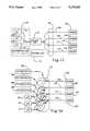
- FIG. 1is a block diagram of a pressure sensing system in accordance with a first embodiment of this invention.
- FIG. 2ais a wavelength versus transmission spectrum showing three different wavelength sources and the transmission characteristic of a optical filament filter coating used to provide temperature compensation in accordance with an embodiment of this invention.
- FIG. 2bis a wavelength versus transmission spectrum showing three different wavelength sources like that shown in FIG. 2a but showing a peaked transmission response of the filter coating overlapping one source for temperature sensitivity.
- FIG. 3is a wavelength versus transmission spectrum showing a method for temperature compensation based on differential temperature modulation of light signals based on their launching conditions.
- FIG. 4is a pictorial view showing a light source providing a launching condition for an inputted light which produces maximum intensity near the fiber outer surfaces.
- FIG. 5is a pictorial view showing a light source providing a launching condition for an inputted light which produces maximum intensity near the fiber center.
- FIG. 6is a cross sectional view of a sensing tip of this invention defining a closed gas volume acting on one side of the sensing diaphragm.
- FIG. 7is a pictorial view of a fiber optic pressure sensing tip with cable and optical connector in accordance with this invention which provides a means for shielding the deformable pressure sensing element of the sensing tip.
- FIG. 8is a wavelength versus transmission distribution for a system according to an embodiment of this invention for reducing calibration error by allowing a portion of the reference light signal to leak past the fiber en coating in which the transmission curve has an elevated minimum transmission characteristic.
- FIG. 9is a wavelength versus transmission distribution for a system similar to that of FIG. 7 except that the filter cut-off wavelength partly overlaps the reference light source spectrum.
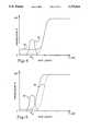
- FIG. 10is a curve showing a reduction in error attributable to operation in accordance with FIGS. 7 or 8.
- FIG. 11is a schematic drawing of a multiplexing system in which a common photodetector is used to monitor the output from plural sensors.
- FIG. 12shows an optical shutter system used in conjunction with the system of FIG. 11 using optoelectric shutters.
- FIG. 13shows an optical modulation system used in conjunction with the system of FIG. 11 using piezoelectric microbend attenuators.
- FIG. 14is a schematic drawing of multiplexing system in which a common set of light sources is used with designated photodetectors for each sensor.
- FIG. 1A generalized fiber optic pressure sensing system is shown in FIG. 1 and is generally designated there by reference number 10.
- System 10includes fiber optic cable 12 which has a sensing tip 14 at its terminal end.
- Optical filament 11passes through ferrule 13 to which it is bonded or interference fit.
- Cylinder 15surrounds ferrule 13.
- Deflectable diaphragm cap 16has a center membrane portion which deforms in response to pressure differentials across it, and thus changes the amplitude of light launched into optical filament 11 at the opposite end of the filament which is returned back into the filament.
- a vent passage 19is provided to maintain the fiber side of the diaphragm cap 16 at a desired pressure.
- FIG. 1A temperature compensating system using optical means of temperature measurement according to an embodiment of this invention is shown in FIG. 1.
- the system 10consists of an opto-electronic interface 18 containing three LEDs 20, 22 and 24, each emitting light in distinct wavelength bands; photodetectors 26 and 28; and a coupler (not shown) for launching light from the LEDs into optical filament 11, and directing the returned signals to be incident on the photodetectors. Some of the light from the LED's is directed to fall on photodetector 26 which provides a source intensity reference.
- Three output signals from the opto-electronic interface 18are converted into a digital form by A to D converter 28 and transmitted to digital signal processing (DSP) module 34. These three signals are related to the intensity of the returned signals of the three LEDs.
- the outputs of module 30are pressure and temperature readings.
- the DSP module 34 and associated host microprocessorcontrol the operation of LEDs 20, 22 and 24, and perform real time computations and conversions.
- a computation algorithmis used to deconvolve temperature effects from the pressure output and is derived from the fundamental relationships between diaphragm deflection, pressure, and temperature. Experimentally derived correction factors may be also used as inputs to the compensation algorithm.
- the deflection of the diaphragm cap 16is measured using the dual wavelength technique described in U.S. Pat. No. 4,924,870 in which the light signal from LED 20 is reflected by filter layer 17, whereas the light pulse from LED 24 passes through the filter to be modulated by diaphragm cap 16.
- the use of the referencing wavelength from LED 20 in this approachpermits compensation for environmental effects on the system such as vibration, connector instability, bending effects, and some of the sensing tip sensitivities.
- Fiber optic temperature measurement of the sensor tip 14is performed in a novel way according to this invention and does not require any modifications to the sensor designed for dual wavelength operation but instead only requires modifications to interface 18. This is an important consideration for price sensitive applications, such as in automobiles, where the price of replaceable elements has to be very low.
- temperatureis measured by monitoring the intensity of the third wavelength produced by LED 2 returned into the fiber at sensing tip 14, and time division multiplexed the signal from photodetector 28 with the other two wavelengths.
- This temperature sensitive wavelengthis selected such that the corresponding signal is most sensitive to temperature changes at the sensor tip 14.
- One location for the wavelengthis between the other two wavelength bands produced by LEDs 20 and 24, and overlapping with the cut-off wavelength of filter 17.
- the output spectra of LEDs 20, 22 and 24are shown as curves 36, 38 and 40, and can be designated as the reference, temperature and pressure sensitive wavelengths, respectively.
- the cut-off slope of filter 17, designated by curve 42moves around its nominal position at a temperature T 2 .
- T 1the cut-off slope moves towards shorter wavelengths, increasing the intensity of the transmitted temperature sensing wavelength (lambda t ). If the coating parameters are correctly selected, the transmission levels of the reference wavelength light (lambda r ) and the pressure sensitive wavelength light (lambda p ) change very little.
- the cut-off slope of the transmission curveis not the only temperature sensitive range of the curve.
- a region of the curve exhibiting the side-lobe behavioras shown in FIG. 2b designated by reference number 43, exhibits possibly even higher temperature sensitivity because it is typically narrow than the line-width of LED 20 and it shifts by the same amount that the cut-off slope does.
- an alternative temperature measuring techniqueis possible, as shown schematically in FIG. 2b.
- the temperature dependent changes in lambda tare obtained by taking a ratio of the signals at lambda p and lambda t where:
- V p (p,t)is the intensity of lambda p
- V t (p,t) of lambda tis modulated by both pressure and temperature, however the ratio v t depends only on temperature. In operation, the LEDs 20, 22 and 24 would be fired sequentially with the output of photodetector 28 gated to ensure output synchronization.
- Temperature sensingis also possible within a flat portion of the transmission curve as shown in FIG. 3.
- a necessary conditionis that the temperature sensing wavelength is differently affected by temperature than the referencing wavelength.
- a novel technique, and an alternative to the technique described above,is to differentiate the temperature effect between the referencing and temperature sensing wavelengths through the differentiating of the launching conditions between the two wavelengths. This can be accomplished in a simple manner in optoelectronic interface 18 by restricting the numerical aperture of the pressure and reference sensing LEDs (underfilling the launch) or overfilling the modes for the measuring wavelengths. For short fibers, such as of interest here, the launching condition at interface 18 is very well preserved all the way to sensing tip 14 and back to the interface such that the two wavelengths have different modal distributions.
- a different launch conditionmay result, in principle, in somewhat different sensitivity to filament bending, and fiber or connector instabilities.
- temperature effects at sensing tip 14are so large that the launching mismatch needed for temperature measurement does not significantly affect sensitivities to other environmental effects.
- FIGS. 4 and 5provide simplified illustrations of techniques for providing different launching conditions for two signals which are differentially affected by temperature.
- LED 44is shown projecting light through aperture 46 and into fiber optic filament 11.
- Aperture 46has the property that it blocks light from entering at near the center longitudinal axis of filament 11 and, therefore, produces a maximum intensity distribution which is near the radially outer surface of the filament.
- this launching conditionis well preserved along filament 11 and, therefore, an intensity distribution of light through any cross-section of the filament will reveal peak intensities near the outer surface of the filament.
- FIG. 5is similar to FIG. 4, except showing aperture 48 which produces a maximum intensity along the central longitudinal axis of filament 11. In that launching condition, a maximum light intensity distribution will be found around the center core area of the filament.
- the effectiveness of the temperature compensation described in this inventiondepends on the ability of accurately relating the signals v p and v t . In principal, these signals are coupled through three effects: the fundamental thermo-mechanical properties of the diaphragm cap 16 material, the temperature expansion of the elements of sensing tip 14, and the pressure and temperature dependent transmission changes of the optical signals.
- a temperature compensated pressure readingis obtained by what is equivalent to a real time inversion of the functional dependence between the changes in optical signal and diaphragm deflection, which in turn depends on both temperature and pressure as follows:
- a particular look-up or curve fitting techniqueis implemented based on two primary factors: the degree of the accuracy of the theoretical model, and the accuracy of the deflection and temperature readings.
- the correction factorsare identical for all sensors and identical correction parameters are stored in the memory of the system based on an unique inversion relationship.
- some kind of individual sensor calibrationneeds to be instituted because of the manufacturing variability.
- a two (or more) point calibration techniquecould be implemented.
- Time dependent changes in the optical system of sensor 10can be expected to occur resulting for example, from reflectivity changes of diaphragm cap 16, and changes in the transmission of the optical filament 11.
- a zero-offset techniquecan be implemented.
- "re-zeroing" of the sensor pressure outputcan be provided during the engine shut-off periods when the combustion chamber pressure is equal to the atmospheric pressure. Because combustion pressure does not instantaneously reach atmospheric pressure after the engine shuts down, alternative verification of the pressure equilibrium is needed. One way of doing so is to wait a certain amount of time after engine shut down. The necessary delay can be easily determined and stored electronically. In an automobile, this re-zeroing can also be performed during the regular engine status check preceding engine ignition.
- the reflecting diaphragm 16, the optical coating 17, and the bonding material usedmay deteriorate over time.
- Periodic calibration described abovewill be effective if the resulting changes in optical signals are smaller than required by the dynamic range of the system.
- a technique of sealing of the area between the fiber 11 end face and diaphragm 16is described here. As shown in FIG. 6, the area behind diaphragm 16 is not vented to atmospheric pressure. If a gas is used to fill this space, temperature dependent back pressure changes will result. However, this temperature effect is well behaved and will be compensated for by the temperature compensation technique described in this specification.
- An inert gassuch as for example argon, would be used eliminating any residues of oxygen and water vapor that are the main causes of potential optical changes inside the sensor.
- the sealed gaswill exert pressure on diagram cap 16 as dictated by the Ideal Gas Law. The changes in this pressure would be a component of a lumped correction parameter.
- vent passage 30as shown in FIG. 1 could be used to enlarge the sealed volume.
- vent passage 30would be plugged along fiber optic cable 12 along its length or at interface 18.
- the advantage of such a configurationis that for some applications, such as combustion chamber pressure measurement, the average temperature of the sealed gas would be closer to ambient temperature, thus reducing the pressure change acting on diagram 16 dictated by the Ideal Gas Law, and further reducing the rate of temperature change of the trapped gas.
- diaphragm cap 16Another critical issue for long term accuracy and reliability of a fiber optic sensor system is the mechanical stability and durability of the material of diaphragm cap 16.
- a diaphragm directly exposed to the combustion chambermay be subjected to temperature between -50 degrees C. and 550 degrees C. This represents a daunting environment for the most temperature resilient metals.
- fiber optic cable 12is shown specifically adapted for incorporation into an automotive internal combustion engine for measuring combustion chamber pressure.
- Fiber optic cable 12is shown housed within mounting plug 52, which is threaded to be received in an associated port exposed to the combustion chamber.
- mounting plug 52has an internal cavity for supporting fiber optic cable 12.
- the opposite end of the cable 12has an optical connector 54.
- a shield 56is provided, positioned between sensing tip 14 and the combustion chamber. Shield 56 is made from sintered material such as that frequently employed in pressure lines.
- Such a materialis made of pressed metal bids (can be stainless steel or brass) which form a porous structure of very high heat mass capable of rapid temperature increases.
- Shield 56is in the form of a disk, a few millimeter thick, thermally coupled to mounting plug 52 and reduces temperature extremes by hundreds of degrees. Furthermore, this material does not reduce the frequency response of the sensor. By selecting the size and material of the bids, disk 56 may additionally attenuate high frequency jitter on the pressure waveforms as may result from the presence of the cavity above the sensor diaphragm.
- An additional benefit of placing shield 56 in front of sensing tip 14is protection of diaphragm cap 16 against formation of deposits on its surface. Such deposits may alter the diaphragm's dynamic characteristics over prolonged operation and result in sensor inaccuracies.
- This aspect of the inventionrelates to an improvement to the dual wavelength technique that results in significant reduction in the differential effect at the tip and overall reduction in sensor error. This benefit is achieved without a direct measurement of sensing tip 14 temperature, as is conducted in accordance with the prior embodiments.
- the basic principal of this embodiment of the inventionis allowing the reference wavelength light signal to partially leak through coating 17 and benefit from the resulting larger reduction in the differential effect at sensing tip 14 compared to the reduction in the full scale pressure change (span).
- the transmission curve of coating 17is modified compared to the original profile shown in FIGS. 2 and 3 such that the reference signal is partially transmitted.
- Two approachesare depicted by the figures for allowing the reference light signal to be partially transmitted.
- the modified transmission curve 58 of filter 17is shown in which the transmissance of the filter does not reach zero within the range of wavelengths of interest. As shown in FIG. 8, a large proportion of the total energy of the reference wavelength is transmitted past filter coating 17.
- partial leakage of the reference wavelength light signalis achieved by partially overlapping the cut-off range of filter 17 with the reference wavelength signal, using a filter with the characteristics of curve 60. Care has to be exercised in selecting an optical source such that launching condition is essentially the same for both the reference and pressure sensing wavelengths. Low bend sensitivity can be used as a test of good launch overlap.
- the benefit of leaking a portion of the reference wavelength light signalstems from the dependence of the ratio of tip sensitivity and span.
- the intensity of the two signalscan be expressed as:
- I iis the intensity of the signals
- F iis the transmission factor representing the lumped transmission coefficient of filament 11 up to the fiber end
- R i and T iare the reflection and transmission coefficients, respectively, of the coating
- Dis the pressure dependent reflection coefficient of the diaphragm.
- the voltage output of the sensoris proportional to the ratio of the signals of the previous equation.
- the span of the sensorcan be expressed, in a small change approximation, as
- FIG. 10illustrates that increases in transmission coefficient results in lower error.
- this disclosuredescribes techniques of multiplexing a number of identical sensors 14a through d that can perform simultaneous pressure measurements. Such measurements are needed for automotive engine controls based on combustion pressure measured in individual engine cylinders. Two schemes are described here: a first that utilizes a single measuring photo detector as shown in FIG. 11, and a second based on multiple of measuring detectors, shown in FIG. 14.
- the multiplexing scheme shown in FIG. 11is a combination of three techniques: wavelength, time, and frequency multiplexing. Wavelength and time division multiplexing are used as previously described, for compensating for temperature and environmental effects acting on an individual sensor. Frequency multiplexing is employed to multiplex different sensors shown as 14a through d without increasing the complexity and cost of the opto-electronic interface 18. This modulation is realized by using electronically driven shutters integrated within an in-line connector 64 which are operated by controller 74.
- FIG. 12One approach, as depicted in FIG. 12, is based on four piezoelectrically driven shutters 66a through d introduced between the ends of interconnecting fibers 11a through d. This technique requires the use of an expanded beam connector between the fibers 11a through d and mixing rod 70 to minimize transmission losses resulting from separation of the fibers.
- piezoelectric squeezer shutters 68a through dapply pressure alongside the fiber. If the squeezer 68 has a tooth-like shape, intensity modulation can be induced through the microbending effect. It is further contemplated that liquid crystal shutters could be employed. This approach eliminates the use of mechanical devices and ensures long time reliability.
- the shutters 66 or 68can operate in two alternative modes.
- One moderequires that all four shutters continuously close and open, each at different frequency.
- the signals of different frequenciesare separated then using phase sensitive detection.
- phase sensitive detectionoffers additional benefits of improved signal-to-noise ratio.
- An alternative approachrequires opening and closing the shutters 66 or 68 sequentially.
- Each of the sensors 14a through dis interrogated at a different time in essentially the same manner as in the case of an individual sensor.
- Each of the four channelscomprises fibers 11a through d carry the three time division multiplexed signals corresponding to the three wavelengths 36, 38 and 40. These signals are processed by the DSP module 34 to extract the pressure and temperature information for each sensor 14a through d. Four pressure outputs from DSP module 34 are transmitted then in an appropriate format to an Electronic Control Module (ECM) of an automobile.
- ECMElectronic Control Module
- FIG. 14A time division multiplexed multiple detector design is used.
- Each of the three LEDs 20, 22 and 24is connected, via a fiber lens interface 72, to each of the four sensing fibers 11a through d.
- the return signal from each of the fibers 11a through dis detected by individual measuring detectors 28a through d, provided for each sensor 14a through d.
- the signals of the four detectors 28a through dare processed independently, synchronized to the emitting LEDs 20, 22 and 24 the same way it is done for a single channel sensor described herein.
Landscapes
- Physics & Mathematics (AREA)
- General Physics & Mathematics (AREA)
- Chemical & Material Sciences (AREA)
- Engineering & Computer Science (AREA)
- Combustion & Propulsion (AREA)
- Measuring Fluid Pressure (AREA)
- Arrangements For Transmission Of Measured Signals (AREA)
Abstract
Description
v(t)=V.sub.t (p,t)/V.sub.p (p)
and
V.sub.t (p,t)=V.sub.t (t) * V.sub.t (p)
v.sub.out (p)=F.sup.-1 {v.sub.t ]v.sub.d (p,t),t]}V.sub.i =I.sub.i F.sub.i (R.sub.i +T.sub.i.sup.2 D)
V.sub.o =V.sub.m /V.sub.r =(R.sub.m +T.sub.m.sup.2 D)/(R.sub.r +T.sub.r.sup.2 D)
W=dI.sub.m /I.sub.m -dI.sub.r /I.sub.r =(r+2T.sub.m t D)/(R.sub.m +T.sub.m.sup.2 D)=(r+2 T.sub.r t D)/(R.sub.r +T.sub.r.sup.2 D)
S=T.sub.m.sup.2 /(R.sub.m +T.sub.m.sup.2 D)-T.sub.m.sup.2 /(R.sub.m +T.sub.m.sup.2 D)
Error=W/S
Claims (17)
Priority Applications (5)
| Application Number | Priority Date | Filing Date | Title |
|---|---|---|---|
| US07/748,082US5275053A (en) | 1991-08-21 | 1991-08-21 | Fiber optic pressure sensor systems |
| CA002068033ACA2068033A1 (en) | 1991-08-21 | 1992-05-05 | Fiberoptic pressure sensor systems |
| JP4181109AJPH05196528A (en) | 1991-08-21 | 1992-07-08 | Optical fiber pressure sensor device |
| EP19920307449EP0528657A3 (en) | 1991-08-21 | 1992-08-14 | Improved fiber optic pressure sensor systems |
| US08/132,718US5385053A (en) | 1991-08-21 | 1993-10-06 | Fiber optic pressure sensor systems |
Applications Claiming Priority (1)
| Application Number | Priority Date | Filing Date | Title |
|---|---|---|---|
| US07/748,082US5275053A (en) | 1991-08-21 | 1991-08-21 | Fiber optic pressure sensor systems |
Related Child Applications (1)
| Application Number | Title | Priority Date | Filing Date |
|---|---|---|---|
| US08/132,718DivisionUS5385053A (en) | 1991-08-21 | 1993-10-06 | Fiber optic pressure sensor systems |
Publications (1)
| Publication Number | Publication Date |
|---|---|
| US5275053Atrue US5275053A (en) | 1994-01-04 |
Family
ID=25007926
Family Applications (2)
| Application Number | Title | Priority Date | Filing Date |
|---|---|---|---|
| US07/748,082Expired - LifetimeUS5275053A (en) | 1991-08-21 | 1991-08-21 | Fiber optic pressure sensor systems |
| US08/132,718Expired - LifetimeUS5385053A (en) | 1991-08-21 | 1993-10-06 | Fiber optic pressure sensor systems |
Family Applications After (1)
| Application Number | Title | Priority Date | Filing Date |
|---|---|---|---|
| US08/132,718Expired - LifetimeUS5385053A (en) | 1991-08-21 | 1993-10-06 | Fiber optic pressure sensor systems |
Country Status (4)
| Country | Link |
|---|---|
| US (2) | US5275053A (en) |
| EP (1) | EP0528657A3 (en) |
| JP (1) | JPH05196528A (en) |
| CA (1) | CA2068033A1 (en) |
Cited By (67)
| Publication number | Priority date | Publication date | Assignee | Title |
|---|---|---|---|---|
| US5422478A (en)* | 1992-04-17 | 1995-06-06 | Fiberoptic Sensor Technologies, Inc. | Fiberoptic pressure sensor having drift correction means for insitu calibration |
| US5446280A (en)* | 1993-08-31 | 1995-08-29 | Center For Innovative Technology | Split-spectrum self-referenced fiber optic sensor |
| US5446279A (en)* | 1993-08-27 | 1995-08-29 | Hughes Aircraft Company | Fiber optic sensor sensing curvature of a diaphragm |
| US5657163A (en)* | 1995-05-31 | 1997-08-12 | Delco Electronics Corporation | Fiber optic illumination of HUD image source |
| WO1998017988A1 (en)* | 1996-10-23 | 1998-04-30 | Optrand, Inc. | Integrated fiber optic combustion pressure sensor |
| US5747793A (en)* | 1995-10-04 | 1998-05-05 | Advanced Fiber Optechs, Inc. | Variable light source compensated optical fiber sensing system |
| US5763769A (en)* | 1995-10-16 | 1998-06-09 | Kluzner; Michael | Fiber optic misfire, knock and LPP detector for internal combustion engines |
| US5832157A (en)* | 1996-07-12 | 1998-11-03 | Mcdermott Technology, Inc. | Fiber optic acoustic emission sensor |
| US5987995A (en)* | 1997-07-17 | 1999-11-23 | Sentec Corporation | Fiber optic pressure catheter |
| WO2000017618A1 (en)* | 1998-09-22 | 2000-03-30 | Hutton Peter B | Pressure-measuring device and method using flexible, light-reflective foil |
| US6097478A (en)* | 1998-04-02 | 2000-08-01 | Mcdermott Technology, Inc. | Fiber optic acoustic emission sensor |
| US6094990A (en)* | 1998-06-30 | 2000-08-01 | Cooper Automotive Products, Inc. | Spark plug with concentric pressure sensor |
| US6204594B1 (en) | 1998-06-12 | 2001-03-20 | Cooper Automotive Products, Inc. | Spark plug with pressure sensor |
| US6301957B1 (en)* | 1997-12-15 | 2001-10-16 | Hitachi, Ltd. | Fiber-optic cylinder pressure sensor |
| US6525307B1 (en)* | 1999-09-16 | 2003-02-25 | Ut-Battelle, Llc | Integrated optical interrogation of micro-structures |
| US20040031326A1 (en)* | 2002-06-11 | 2004-02-19 | Thomas Lenzing | Fiber-optic pressure sensor |
| US20040074281A1 (en)* | 2002-10-16 | 2004-04-22 | Lobdell Donn D. | Testing of pressure sensor in surgical cassette |
| US20040261534A1 (en)* | 2003-06-30 | 2004-12-30 | Mikhail Boukhny | Noninvasive pressure sensing assembly |
| US6955073B2 (en) | 2002-10-16 | 2005-10-18 | Alcon, Inc. | Pressure sensing in surgical console |
| US20050243308A1 (en)* | 1999-06-18 | 2005-11-03 | Samba Sensors Ab | Method and a device for bending compensation in intensity-based fibre-optical measuring systems |
| US20060011820A1 (en)* | 2004-07-16 | 2006-01-19 | Kin-Man Yip And Chow-Shing Shin | Fiber-optic sensing system |
| US20060204164A1 (en)* | 2005-03-08 | 2006-09-14 | Gennadii Ivtsenkov | Low cost fiber-optic gage and associated multi-channel all-optical data collecting system |
| US20070165238A1 (en)* | 2006-01-13 | 2007-07-19 | Luna Innovations Incorporated | Demodulation method and apparatus for fiber optic sensors |
| US20090027659A1 (en)* | 1999-06-18 | 2009-01-29 | Sambra Sensors Ab | Measuring system for measuring a physical parameter influencing a sensor element |
| US20090156926A1 (en)* | 2007-11-26 | 2009-06-18 | C.R. Bard, Inc. | Integrated System for Intravascular Placement of a Catheter |
| US20090203989A1 (en)* | 2008-02-11 | 2009-08-13 | C. R. Bard, Inc. | Systems and methods for positioning a catheter |
| US20090234328A1 (en)* | 2007-11-26 | 2009-09-17 | C.R. Bard, Inc. | Systems and methods for breaching a sterile field for intravascular placement of a catheter |
| US20090259124A1 (en)* | 2006-10-23 | 2009-10-15 | Rothenberg Peter M | Method of locating the tip of a central venous catheter |
| US20100222664A1 (en)* | 2008-08-22 | 2010-09-02 | C. R. Bard. Inc. | Catheter assembly including ecg sensor and magnetic assemblies |
| US7794407B2 (en) | 2006-10-23 | 2010-09-14 | Bard Access Systems, Inc. | Method of locating the tip of a central venous catheter |
| US20110087107A1 (en)* | 2009-10-08 | 2011-04-14 | C.R. Bard, Inc. | Spacers for use with an ultrasound probe |
| US20120165996A1 (en)* | 2009-08-06 | 2012-06-28 | Vestas Wind Systems A/S | Rotor blade control based on detecting turbulence |
| US8437833B2 (en) | 2008-10-07 | 2013-05-07 | Bard Access Systems, Inc. | Percutaneous magnetic gastrostomy |
| USD699359S1 (en) | 2011-08-09 | 2014-02-11 | C. R. Bard, Inc. | Ultrasound probe head |
| US8760637B2 (en) | 2010-08-30 | 2014-06-24 | Alcon Research, Ltd. | Optical sensing system including electronically switched optical magnification |
| US8781555B2 (en) | 2007-11-26 | 2014-07-15 | C. R. Bard, Inc. | System for placement of a catheter including a signal-generating stylet |
| US8784336B2 (en) | 2005-08-24 | 2014-07-22 | C. R. Bard, Inc. | Stylet apparatuses and methods of manufacture |
| US8801693B2 (en) | 2010-10-29 | 2014-08-12 | C. R. Bard, Inc. | Bioimpedance-assisted placement of a medical device |
| US8849382B2 (en) | 2007-11-26 | 2014-09-30 | C. R. Bard, Inc. | Apparatus and display methods relating to intravascular placement of a catheter |
| US20150020599A1 (en)* | 2012-03-16 | 2015-01-22 | Oxsensis Ltd | Optical pressure sensor |
| USD724745S1 (en) | 2011-08-09 | 2015-03-17 | C. R. Bard, Inc. | Cap for an ultrasound probe |
| US9125578B2 (en) | 2009-06-12 | 2015-09-08 | Bard Access Systems, Inc. | Apparatus and method for catheter navigation and tip location |
| US9211107B2 (en) | 2011-11-07 | 2015-12-15 | C. R. Bard, Inc. | Ruggedized ultrasound hydrogel insert |
| US9339206B2 (en) | 2009-06-12 | 2016-05-17 | Bard Access Systems, Inc. | Adaptor for endovascular electrocardiography |
| US9445734B2 (en) | 2009-06-12 | 2016-09-20 | Bard Access Systems, Inc. | Devices and methods for endovascular electrography |
| US9456766B2 (en) | 2007-11-26 | 2016-10-04 | C. R. Bard, Inc. | Apparatus for use with needle insertion guidance system |
| US9492097B2 (en) | 2007-11-26 | 2016-11-15 | C. R. Bard, Inc. | Needle length determination and calibration for insertion guidance system |
| US9521961B2 (en) | 2007-11-26 | 2016-12-20 | C. R. Bard, Inc. | Systems and methods for guiding a medical instrument |
| US9532724B2 (en) | 2009-06-12 | 2017-01-03 | Bard Access Systems, Inc. | Apparatus and method for catheter navigation using endovascular energy mapping |
| US9554716B2 (en) | 2007-11-26 | 2017-01-31 | C. R. Bard, Inc. | Insertion guidance system for needles and medical components |
| US9636031B2 (en) | 2007-11-26 | 2017-05-02 | C.R. Bard, Inc. | Stylets for use with apparatus for intravascular placement of a catheter |
| US20170152814A1 (en)* | 2015-12-01 | 2017-06-01 | GM Global Technology Operations LLC | Purge Pressure Sensor Offset And Diagnostic Systems And Methods |
| US9839372B2 (en) | 2014-02-06 | 2017-12-12 | C. R. Bard, Inc. | Systems and methods for guidance and placement of an intravascular device |
| US10046139B2 (en) | 2010-08-20 | 2018-08-14 | C. R. Bard, Inc. | Reconfirmation of ECG-assisted catheter tip placement |
| US10190515B2 (en) | 2015-12-01 | 2019-01-29 | GM Global Technology Operations LLC | Fuel vapor flow estimation systems and methods |
| US10267247B2 (en) | 2015-12-01 | 2019-04-23 | GM Global Technology Operations LLC | Purge pump control systems and methods |
| US10349890B2 (en) | 2015-06-26 | 2019-07-16 | C. R. Bard, Inc. | Connector interface for ECG-based catheter positioning system |
| US10449330B2 (en) | 2007-11-26 | 2019-10-22 | C. R. Bard, Inc. | Magnetic element-equipped needle assemblies |
| US10524691B2 (en) | 2007-11-26 | 2020-01-07 | C. R. Bard, Inc. | Needle assembly including an aligned magnetic element |
| US10639008B2 (en) | 2009-10-08 | 2020-05-05 | C. R. Bard, Inc. | Support and cover structures for an ultrasound probe head |
| US10751509B2 (en) | 2007-11-26 | 2020-08-25 | C. R. Bard, Inc. | Iconic representations for guidance of an indwelling medical device |
| US10820885B2 (en) | 2012-06-15 | 2020-11-03 | C. R. Bard, Inc. | Apparatus and methods for detection of a removable cap on an ultrasound probe |
| US10973584B2 (en) | 2015-01-19 | 2021-04-13 | Bard Access Systems, Inc. | Device and method for vascular access |
| US10992079B2 (en) | 2018-10-16 | 2021-04-27 | Bard Access Systems, Inc. | Safety-equipped connection systems and methods thereof for establishing electrical connections |
| US11000207B2 (en) | 2016-01-29 | 2021-05-11 | C. R. Bard, Inc. | Multiple coil system for tracking a medical device |
| US11125636B2 (en)* | 2018-06-07 | 2021-09-21 | Baker Hughes, A Ge Company, Llc | Quadrature detection for optical MEMS pressure gauge |
| CN120628220A (en)* | 2025-08-18 | 2025-09-12 | 中联德冠科技(北京)有限公司 | A method and system for decoupling mixed signals of high and low temperature alternating environments based on multi-core optical fiber |
Families Citing this family (22)
| Publication number | Priority date | Publication date | Assignee | Title |
|---|---|---|---|---|
| JPH06307953A (en)* | 1993-04-27 | 1994-11-04 | Hitachi Ltd | Physical quantity detection device |
| AUPN297195A0 (en)* | 1995-05-15 | 1995-06-08 | University Of Sydney, The | Optical fibre filter sensor |
| US5689107A (en)* | 1995-09-01 | 1997-11-18 | Hughes Aircraft Company | Displacement-based opto-electronic accelerometer and pressure sensor |
| US5706372A (en)* | 1996-08-12 | 1998-01-06 | Delco Electronics Corporation | Integrated optoelectronic combustion pressure sensor |
| JP2001512564A (en)* | 1997-02-06 | 2001-08-21 | オプトランド,インコーポレイテッド | Injector with built-in fiber optic pressure sensor and associated compensation status monitoring device |
| US6787758B2 (en)* | 2001-02-06 | 2004-09-07 | Baker Hughes Incorporated | Wellbores utilizing fiber optic-based sensors and operating devices |
| US6005242A (en)* | 1997-08-15 | 1999-12-21 | Alconi Sensline | Environmental media and pressure sensor |
| US6612174B2 (en) | 2000-02-11 | 2003-09-02 | Rosemount Inc. | Optical pressure sensor |
| US7191660B2 (en)* | 2004-04-15 | 2007-03-20 | Davidson Instruments Inc. | Flame shield for high temperature pressure transducer |
| RU2270428C1 (en)* | 2004-08-16 | 2006-02-20 | Государственное образовательное учреждение высшего профессионального образования Санкт-Петербургский государственный горный институт им. Г.В. Плеханова (технический университет) | Fiber-optic pressure indicator |
| US7689071B2 (en)* | 2004-12-22 | 2010-03-30 | Opsens Inc. | Fiber optic pressure sensor for catheter use |
| WO2008047859A1 (en) | 2006-10-18 | 2008-04-24 | Fujikura Ltd. | Optical fiber thermometer and temperature compensation optical fiber sensor |
| EP2072986B1 (en)* | 2007-12-18 | 2016-08-10 | Services Pétroliers Schlumberger | A pressure measuring device and method |
| US7697798B2 (en)* | 2008-02-11 | 2010-04-13 | The United States Of America As Represented By The Secretary Of The Navy | Fiber optic pressure sensors and catheters |
| CN103328033B (en) | 2010-11-09 | 2016-05-18 | 奥普森斯公司 | There is the seal wire of internal pressure sensor |
| EP2720020A1 (en) | 2012-10-15 | 2014-04-16 | HIDRIA AET Druzba za proizvodnjo vzignih sistemov in elektronike d.o.o. | Pressure sensing plug with integrated optical pressure sensor |
| US20150090030A1 (en)* | 2013-09-27 | 2015-04-02 | Infineon Technologies Ag | Transducer arrangement comprising a transducer die and method of covering a transducer die |
| KR101970623B1 (en)* | 2017-04-11 | 2019-04-19 | (주)파이버피아 | Apparatus and method for sensing similar gasoline using optical sensor |
| WO2019079689A1 (en)* | 2017-10-20 | 2019-04-25 | University Of Florida Research Foundation, Inc. | Multi-hole probe pressure sensors |
| EP3546697B1 (en)* | 2018-03-30 | 2021-11-03 | FBGS Technologies GmbH | Optical sensing system |
| CN111238822A (en)* | 2018-11-29 | 2020-06-05 | 北京致感致联科技有限公司 | Combustion chamber dynamic pressure on-line monitoring system |
| USD926199S1 (en) | 2019-05-17 | 2021-07-27 | Opsens, Inc. | Display screen or portion thereof with graphical user interface |
Citations (18)
| Publication number | Priority date | Publication date | Assignee | Title |
|---|---|---|---|---|
| US3853386A (en)* | 1972-09-19 | 1974-12-10 | Balzers Patent Beteilig Ag | Low-loss, highly reflective multilayer coating system formed of alternate highly refractive and low-refractive oxide layers |
| US4182935A (en)* | 1976-12-07 | 1980-01-08 | International Standard Electric Corporation | Optical fiber data transmission system |
| US4228349A (en)* | 1978-08-28 | 1980-10-14 | Rca Corporation | III-V Direct-bandgap semiconductor optical filter |
| US4356396A (en)* | 1980-12-17 | 1982-10-26 | Siemens Corporation | Fiber optical measuring device with compensating properties |
| US4487206A (en)* | 1982-10-13 | 1984-12-11 | Honeywell Inc. | Fiber optic pressure sensor with temperature compensation and reference |
| US4523092A (en)* | 1982-07-29 | 1985-06-11 | Aetna Telecommunications Laboratories | Fiber optic sensors for simultaneously detecting different parameters in a single sensing tip |
| US4564755A (en)* | 1982-08-17 | 1986-01-14 | Siemens Aktiengesellschaft | Transmission and reception device for a fiber-optical sensor system |
| US4678904A (en)* | 1984-07-06 | 1987-07-07 | Technology Dynamics, Inc. | Optical measuring device using a spectral modulation sensor having an optically resonant structure |
| US4681395A (en)* | 1985-02-22 | 1987-07-21 | Eldec Corporation | Time-domain intensity normalization for fiber optic sensing |
| US4691709A (en)* | 1986-07-01 | 1987-09-08 | Cordis Corporation | Apparatus for measuring velocity of blood flow in a blood vessel |
| US4703175A (en)* | 1985-08-19 | 1987-10-27 | Tacan Corporation | Fiber-optic sensor with two different wavelengths of light traveling together through the sensor head |
| US4883062A (en)* | 1988-04-25 | 1989-11-28 | Medex, Inc. | Temperture and pressure monitors utilizing interference filters |
| US4911015A (en)* | 1988-11-14 | 1990-03-27 | Asea Brown Boveri Inc. | Non-electrical monitoring of a physical condition |
| US4924870A (en)* | 1989-01-13 | 1990-05-15 | Fiberoptic Sensor Technologies, Inc. | Fiber optic sensors |
| US4986671A (en)* | 1989-04-12 | 1991-01-22 | Luxtron Corporation | Three-parameter optical fiber sensor and system |
| US4991590A (en)* | 1989-01-30 | 1991-02-12 | Martin Goffman Associates | Fiber optic intravascular blood pressure transducer |
| US5018529A (en)* | 1986-06-25 | 1991-05-28 | Radisensor Ab | Miniaturized sensor for physiological pressure measurements |
| US5107847A (en)* | 1983-05-25 | 1992-04-28 | Camino Laboratories | Fiber-optic transducer apparatus |
Family Cites Families (16)
| Publication number | Priority date | Publication date | Assignee | Title |
|---|---|---|---|---|
| US3273447A (en)* | 1963-08-26 | 1966-09-20 | Franklin Institute | Detection and measurement device having a small flexible fiber transmission line |
| CH523509A (en)* | 1970-09-18 | 1972-05-31 | Balzers Patent Beteilig Ag | Interference filter, consisting of a plurality of alternating high and low refractive index light-permeable layers on a light-permeable carrier, which reflects a certain wavelength band within a certain wavelength range, but allows the radiation of the other parts of the mentioned range to pass through |
| US3962062A (en)* | 1974-12-09 | 1976-06-08 | Northern Electric Company Limited | Sputtered dielectric thin films |
| US4313647A (en)* | 1975-12-23 | 1982-02-02 | Mamiya Koki Kabushiki Kaisha | Nonreflective coating |
| SE413555B (en)* | 1978-09-15 | 1980-06-02 | Asea Ab | FIBEROPTICAL METDON |
| US4210029A (en)* | 1979-05-04 | 1980-07-01 | Lad Research Industries, Inc. | Differential fiber optic differential pressure sensor |
| DE3106993A1 (en)* | 1980-01-18 | 1982-09-09 | Robert Bosch Gmbh, 7000 Stuttgart | Sensor arrangement |
| DE3011501C2 (en)* | 1980-03-25 | 1994-01-20 | Siemens Ag | Optical edge filter |
| US4620093A (en)* | 1983-10-31 | 1986-10-28 | Rockwell International Corporation | Optical pressure sensor |
| JPS61296304A (en)* | 1985-06-25 | 1986-12-27 | Horiba Ltd | Interference filter made of multi-layered film |
| JPS6212827A (en)* | 1985-07-10 | 1987-01-21 | Hitachi Ltd | Detector for combustion pressure of engine |
| EP0215371A3 (en)* | 1985-09-17 | 1989-01-04 | Siemens Aktiengesellschaft | Edge interference filters for a wavelength division multiplexing optical communication system |
| EP0215372A3 (en)* | 1985-09-17 | 1989-01-04 | Siemens Aktiengesellschaft | Edge interference filters for a wavelength division multiplexing optical communication system |
| US4711246A (en)* | 1986-09-02 | 1987-12-08 | Fiberoptic Sensor Technologies, Inc. | Fiber optic coupled pressure transducer using single fiber and method of fabrication |
| US4787396A (en)* | 1987-06-18 | 1988-11-29 | Fiberoptic Sensor Technologies, Inc. | Fiberoptic pressure transducer |
| US5325865A (en)* | 1990-02-26 | 1994-07-05 | Baxter International, Inc. | Intracranial pressure monitoring system |
- 1991
- 1991-08-21USUS07/748,082patent/US5275053A/ennot_activeExpired - Lifetime
- 1992
- 1992-05-05CACA002068033Apatent/CA2068033A1/ennot_activeAbandoned
- 1992-07-08JPJP4181109Apatent/JPH05196528A/enactivePending
- 1992-08-14EPEP19920307449patent/EP0528657A3/ennot_activeWithdrawn
- 1993
- 1993-10-06USUS08/132,718patent/US5385053A/ennot_activeExpired - Lifetime
Patent Citations (18)
| Publication number | Priority date | Publication date | Assignee | Title |
|---|---|---|---|---|
| US3853386A (en)* | 1972-09-19 | 1974-12-10 | Balzers Patent Beteilig Ag | Low-loss, highly reflective multilayer coating system formed of alternate highly refractive and low-refractive oxide layers |
| US4182935A (en)* | 1976-12-07 | 1980-01-08 | International Standard Electric Corporation | Optical fiber data transmission system |
| US4228349A (en)* | 1978-08-28 | 1980-10-14 | Rca Corporation | III-V Direct-bandgap semiconductor optical filter |
| US4356396A (en)* | 1980-12-17 | 1982-10-26 | Siemens Corporation | Fiber optical measuring device with compensating properties |
| US4523092A (en)* | 1982-07-29 | 1985-06-11 | Aetna Telecommunications Laboratories | Fiber optic sensors for simultaneously detecting different parameters in a single sensing tip |
| US4564755A (en)* | 1982-08-17 | 1986-01-14 | Siemens Aktiengesellschaft | Transmission and reception device for a fiber-optical sensor system |
| US4487206A (en)* | 1982-10-13 | 1984-12-11 | Honeywell Inc. | Fiber optic pressure sensor with temperature compensation and reference |
| US5107847A (en)* | 1983-05-25 | 1992-04-28 | Camino Laboratories | Fiber-optic transducer apparatus |
| US4678904A (en)* | 1984-07-06 | 1987-07-07 | Technology Dynamics, Inc. | Optical measuring device using a spectral modulation sensor having an optically resonant structure |
| US4681395A (en)* | 1985-02-22 | 1987-07-21 | Eldec Corporation | Time-domain intensity normalization for fiber optic sensing |
| US4703175A (en)* | 1985-08-19 | 1987-10-27 | Tacan Corporation | Fiber-optic sensor with two different wavelengths of light traveling together through the sensor head |
| US5018529A (en)* | 1986-06-25 | 1991-05-28 | Radisensor Ab | Miniaturized sensor for physiological pressure measurements |
| US4691709A (en)* | 1986-07-01 | 1987-09-08 | Cordis Corporation | Apparatus for measuring velocity of blood flow in a blood vessel |
| US4883062A (en)* | 1988-04-25 | 1989-11-28 | Medex, Inc. | Temperture and pressure monitors utilizing interference filters |
| US4911015A (en)* | 1988-11-14 | 1990-03-27 | Asea Brown Boveri Inc. | Non-electrical monitoring of a physical condition |
| US4924870A (en)* | 1989-01-13 | 1990-05-15 | Fiberoptic Sensor Technologies, Inc. | Fiber optic sensors |
| US4991590A (en)* | 1989-01-30 | 1991-02-12 | Martin Goffman Associates | Fiber optic intravascular blood pressure transducer |
| US4986671A (en)* | 1989-04-12 | 1991-01-22 | Luxtron Corporation | Three-parameter optical fiber sensor and system |
Cited By (122)
| Publication number | Priority date | Publication date | Assignee | Title |
|---|---|---|---|---|
| US5422478A (en)* | 1992-04-17 | 1995-06-06 | Fiberoptic Sensor Technologies, Inc. | Fiberoptic pressure sensor having drift correction means for insitu calibration |
| US5446279A (en)* | 1993-08-27 | 1995-08-29 | Hughes Aircraft Company | Fiber optic sensor sensing curvature of a diaphragm |
| US5446280A (en)* | 1993-08-31 | 1995-08-29 | Center For Innovative Technology | Split-spectrum self-referenced fiber optic sensor |
| US5657163A (en)* | 1995-05-31 | 1997-08-12 | Delco Electronics Corporation | Fiber optic illumination of HUD image source |
| US5747793A (en)* | 1995-10-04 | 1998-05-05 | Advanced Fiber Optechs, Inc. | Variable light source compensated optical fiber sensing system |
| US5763769A (en)* | 1995-10-16 | 1998-06-09 | Kluzner; Michael | Fiber optic misfire, knock and LPP detector for internal combustion engines |
| US6289143B1 (en) | 1996-07-12 | 2001-09-11 | Mcdermott Technology, Inc. | Fiber optic acoustic emission sensor |
| US5832157A (en)* | 1996-07-12 | 1998-11-03 | Mcdermott Technology, Inc. | Fiber optic acoustic emission sensor |
| WO1998017988A1 (en)* | 1996-10-23 | 1998-04-30 | Optrand, Inc. | Integrated fiber optic combustion pressure sensor |
| US5987995A (en)* | 1997-07-17 | 1999-11-23 | Sentec Corporation | Fiber optic pressure catheter |
| US6301957B1 (en)* | 1997-12-15 | 2001-10-16 | Hitachi, Ltd. | Fiber-optic cylinder pressure sensor |
| US6097478A (en)* | 1998-04-02 | 2000-08-01 | Mcdermott Technology, Inc. | Fiber optic acoustic emission sensor |
| US6204594B1 (en) | 1998-06-12 | 2001-03-20 | Cooper Automotive Products, Inc. | Spark plug with pressure sensor |
| US6094990A (en)* | 1998-06-30 | 2000-08-01 | Cooper Automotive Products, Inc. | Spark plug with concentric pressure sensor |
| WO2000017618A1 (en)* | 1998-09-22 | 2000-03-30 | Hutton Peter B | Pressure-measuring device and method using flexible, light-reflective foil |
| US20050243308A1 (en)* | 1999-06-18 | 2005-11-03 | Samba Sensors Ab | Method and a device for bending compensation in intensity-based fibre-optical measuring systems |
| US20090027659A1 (en)* | 1999-06-18 | 2009-01-29 | Sambra Sensors Ab | Measuring system for measuring a physical parameter influencing a sensor element |
| US6525307B1 (en)* | 1999-09-16 | 2003-02-25 | Ut-Battelle, Llc | Integrated optical interrogation of micro-structures |
| US20040031326A1 (en)* | 2002-06-11 | 2004-02-19 | Thomas Lenzing | Fiber-optic pressure sensor |
| US6820488B2 (en)* | 2002-06-11 | 2004-11-23 | Robert Bosch Gmbh | Fiber-optic pressure sensor |
| US20040074281A1 (en)* | 2002-10-16 | 2004-04-22 | Lobdell Donn D. | Testing of pressure sensor in surgical cassette |
| US6955073B2 (en) | 2002-10-16 | 2005-10-18 | Alcon, Inc. | Pressure sensing in surgical console |
| US6868720B2 (en) | 2002-10-16 | 2005-03-22 | Alcon, Inc. | Testing of pressure sensor in surgical cassette |
| US20040261534A1 (en)* | 2003-06-30 | 2004-12-30 | Mikhail Boukhny | Noninvasive pressure sensing assembly |
| US6941813B2 (en) | 2003-06-30 | 2005-09-13 | Alcon, Inc. | Noninvasive pressure sensing assembly |
| US20060011820A1 (en)* | 2004-07-16 | 2006-01-19 | Kin-Man Yip And Chow-Shing Shin | Fiber-optic sensing system |
| US7196318B2 (en) | 2004-07-16 | 2007-03-27 | Kin-Man Yip | Fiber-optic sensing system |
| US20060204164A1 (en)* | 2005-03-08 | 2006-09-14 | Gennadii Ivtsenkov | Low cost fiber-optic gage and associated multi-channel all-optical data collecting system |
| US10004875B2 (en) | 2005-08-24 | 2018-06-26 | C. R. Bard, Inc. | Stylet apparatuses and methods of manufacture |
| US11207496B2 (en) | 2005-08-24 | 2021-12-28 | C. R. Bard, Inc. | Stylet apparatuses and methods of manufacture |
| US8784336B2 (en) | 2005-08-24 | 2014-07-22 | C. R. Bard, Inc. | Stylet apparatuses and methods of manufacture |
| WO2007087040A3 (en)* | 2006-01-13 | 2009-04-02 | Luna Innovations Inc | Demodulation method and apparatus for fiber optic sensors |
| US20070165238A1 (en)* | 2006-01-13 | 2007-07-19 | Luna Innovations Incorporated | Demodulation method and apparatus for fiber optic sensors |
| US7561276B2 (en) | 2006-01-13 | 2009-07-14 | Luna Innovations Incorporated | Demodulation method and apparatus for fiber optic sensors |
| US9345422B2 (en) | 2006-10-23 | 2016-05-24 | Bard Acess Systems, Inc. | Method of locating the tip of a central venous catheter |
| US8512256B2 (en) | 2006-10-23 | 2013-08-20 | Bard Access Systems, Inc. | Method of locating the tip of a central venous catheter |
| US7794407B2 (en) | 2006-10-23 | 2010-09-14 | Bard Access Systems, Inc. | Method of locating the tip of a central venous catheter |
| US9833169B2 (en) | 2006-10-23 | 2017-12-05 | Bard Access Systems, Inc. | Method of locating the tip of a central venous catheter |
| US9265443B2 (en) | 2006-10-23 | 2016-02-23 | Bard Access Systems, Inc. | Method of locating the tip of a central venous catheter |
| US8388546B2 (en) | 2006-10-23 | 2013-03-05 | Bard Access Systems, Inc. | Method of locating the tip of a central venous catheter |
| US8858455B2 (en) | 2006-10-23 | 2014-10-14 | Bard Access Systems, Inc. | Method of locating the tip of a central venous catheter |
| US8774907B2 (en) | 2006-10-23 | 2014-07-08 | Bard Access Systems, Inc. | Method of locating the tip of a central venous catheter |
| US20090259124A1 (en)* | 2006-10-23 | 2009-10-15 | Rothenberg Peter M | Method of locating the tip of a central venous catheter |
| US10751509B2 (en) | 2007-11-26 | 2020-08-25 | C. R. Bard, Inc. | Iconic representations for guidance of an indwelling medical device |
| US10238418B2 (en) | 2007-11-26 | 2019-03-26 | C. R. Bard, Inc. | Apparatus for use with needle insertion guidance system |
| US9999371B2 (en) | 2007-11-26 | 2018-06-19 | C. R. Bard, Inc. | Integrated system for intravascular placement of a catheter |
| US10105121B2 (en) | 2007-11-26 | 2018-10-23 | C. R. Bard, Inc. | System for placement of a catheter including a signal-generating stylet |
| US8781555B2 (en) | 2007-11-26 | 2014-07-15 | C. R. Bard, Inc. | System for placement of a catheter including a signal-generating stylet |
| US20090234328A1 (en)* | 2007-11-26 | 2009-09-17 | C.R. Bard, Inc. | Systems and methods for breaching a sterile field for intravascular placement of a catheter |
| US11134915B2 (en) | 2007-11-26 | 2021-10-05 | C. R. Bard, Inc. | System for placement of a catheter including a signal-generating stylet |
| US8849382B2 (en) | 2007-11-26 | 2014-09-30 | C. R. Bard, Inc. | Apparatus and display methods relating to intravascular placement of a catheter |
| US8388541B2 (en) | 2007-11-26 | 2013-03-05 | C. R. Bard, Inc. | Integrated system for intravascular placement of a catheter |
| US11123099B2 (en) | 2007-11-26 | 2021-09-21 | C. R. Bard, Inc. | Apparatus for use with needle insertion guidance system |
| US11779240B2 (en) | 2007-11-26 | 2023-10-10 | C. R. Bard, Inc. | Systems and methods for breaching a sterile field for intravascular placement of a catheter |
| US10165962B2 (en) | 2007-11-26 | 2019-01-01 | C. R. Bard, Inc. | Integrated systems for intravascular placement of a catheter |
| US10966630B2 (en) | 2007-11-26 | 2021-04-06 | C. R. Bard, Inc. | Integrated system for intravascular placement of a catheter |
| US10849695B2 (en) | 2007-11-26 | 2020-12-01 | C. R. Bard, Inc. | Systems and methods for breaching a sterile field for intravascular placement of a catheter |
| US9681823B2 (en) | 2007-11-26 | 2017-06-20 | C. R. Bard, Inc. | Integrated system for intravascular placement of a catheter |
| US11707205B2 (en) | 2007-11-26 | 2023-07-25 | C. R. Bard, Inc. | Integrated system for intravascular placement of a catheter |
| US10602958B2 (en) | 2007-11-26 | 2020-03-31 | C. R. Bard, Inc. | Systems and methods for guiding a medical instrument |
| US10231753B2 (en) | 2007-11-26 | 2019-03-19 | C. R. Bard, Inc. | Insertion guidance system for needles and medical components |
| US20090156926A1 (en)* | 2007-11-26 | 2009-06-18 | C.R. Bard, Inc. | Integrated System for Intravascular Placement of a Catheter |
| US10524691B2 (en) | 2007-11-26 | 2020-01-07 | C. R. Bard, Inc. | Needle assembly including an aligned magnetic element |
| US10449330B2 (en) | 2007-11-26 | 2019-10-22 | C. R. Bard, Inc. | Magnetic element-equipped needle assemblies |
| US9456766B2 (en) | 2007-11-26 | 2016-10-04 | C. R. Bard, Inc. | Apparatus for use with needle insertion guidance system |
| US9492097B2 (en) | 2007-11-26 | 2016-11-15 | C. R. Bard, Inc. | Needle length determination and calibration for insertion guidance system |
| US9521961B2 (en) | 2007-11-26 | 2016-12-20 | C. R. Bard, Inc. | Systems and methods for guiding a medical instrument |
| US9526440B2 (en) | 2007-11-26 | 2016-12-27 | C.R. Bard, Inc. | System for placement of a catheter including a signal-generating stylet |
| US10342575B2 (en) | 2007-11-26 | 2019-07-09 | C. R. Bard, Inc. | Apparatus for use with needle insertion guidance system |
| US9549685B2 (en) | 2007-11-26 | 2017-01-24 | C. R. Bard, Inc. | Apparatus and display methods relating to intravascular placement of a catheter |
| US9554716B2 (en) | 2007-11-26 | 2017-01-31 | C. R. Bard, Inc. | Insertion guidance system for needles and medical components |
| US11529070B2 (en) | 2007-11-26 | 2022-12-20 | C. R. Bard, Inc. | System and methods for guiding a medical instrument |
| US9636031B2 (en) | 2007-11-26 | 2017-05-02 | C.R. Bard, Inc. | Stylets for use with apparatus for intravascular placement of a catheter |
| US9649048B2 (en) | 2007-11-26 | 2017-05-16 | C. R. Bard, Inc. | Systems and methods for breaching a sterile field for intravascular placement of a catheter |
| US20090203989A1 (en)* | 2008-02-11 | 2009-08-13 | C. R. Bard, Inc. | Systems and methods for positioning a catheter |
| US8971994B2 (en) | 2008-02-11 | 2015-03-03 | C. R. Bard, Inc. | Systems and methods for positioning a catheter |
| US8478382B2 (en) | 2008-02-11 | 2013-07-02 | C. R. Bard, Inc. | Systems and methods for positioning a catheter |
| US20100222664A1 (en)* | 2008-08-22 | 2010-09-02 | C. R. Bard. Inc. | Catheter assembly including ecg sensor and magnetic assemblies |
| US11027101B2 (en) | 2008-08-22 | 2021-06-08 | C. R. Bard, Inc. | Catheter assembly including ECG sensor and magnetic assemblies |
| US9901714B2 (en) | 2008-08-22 | 2018-02-27 | C. R. Bard, Inc. | Catheter assembly including ECG sensor and magnetic assemblies |
| US8437833B2 (en) | 2008-10-07 | 2013-05-07 | Bard Access Systems, Inc. | Percutaneous magnetic gastrostomy |
| US9907513B2 (en) | 2008-10-07 | 2018-03-06 | Bard Access Systems, Inc. | Percutaneous magnetic gastrostomy |
| US9339206B2 (en) | 2009-06-12 | 2016-05-17 | Bard Access Systems, Inc. | Adaptor for endovascular electrocardiography |
| US9125578B2 (en) | 2009-06-12 | 2015-09-08 | Bard Access Systems, Inc. | Apparatus and method for catheter navigation and tip location |
| US11419517B2 (en) | 2009-06-12 | 2022-08-23 | Bard Access Systems, Inc. | Apparatus and method for catheter navigation using endovascular energy mapping |
| US10912488B2 (en) | 2009-06-12 | 2021-02-09 | Bard Access Systems, Inc. | Apparatus and method for catheter navigation and tip location |
| US9445734B2 (en) | 2009-06-12 | 2016-09-20 | Bard Access Systems, Inc. | Devices and methods for endovascular electrography |
| US10231643B2 (en) | 2009-06-12 | 2019-03-19 | Bard Access Systems, Inc. | Apparatus and method for catheter navigation and tip location |
| US9532724B2 (en) | 2009-06-12 | 2017-01-03 | Bard Access Systems, Inc. | Apparatus and method for catheter navigation using endovascular energy mapping |
| US10271762B2 (en) | 2009-06-12 | 2019-04-30 | Bard Access Systems, Inc. | Apparatus and method for catheter navigation using endovascular energy mapping |
| US20120165996A1 (en)* | 2009-08-06 | 2012-06-28 | Vestas Wind Systems A/S | Rotor blade control based on detecting turbulence |
| US9014863B2 (en)* | 2009-08-06 | 2015-04-21 | Vestas Wind Systems A/S | Rotor blade control based on detecting turbulence |
| US10639008B2 (en) | 2009-10-08 | 2020-05-05 | C. R. Bard, Inc. | Support and cover structures for an ultrasound probe head |
| US11998386B2 (en) | 2009-10-08 | 2024-06-04 | C. R. Bard, Inc. | Support and cover structures for an ultrasound probe head |
| US20110087107A1 (en)* | 2009-10-08 | 2011-04-14 | C.R. Bard, Inc. | Spacers for use with an ultrasound probe |
| US11103213B2 (en) | 2009-10-08 | 2021-08-31 | C. R. Bard, Inc. | Spacers for use with an ultrasound probe |
| US10046139B2 (en) | 2010-08-20 | 2018-08-14 | C. R. Bard, Inc. | Reconfirmation of ECG-assisted catheter tip placement |
| US8760637B2 (en) | 2010-08-30 | 2014-06-24 | Alcon Research, Ltd. | Optical sensing system including electronically switched optical magnification |
| US9415188B2 (en) | 2010-10-29 | 2016-08-16 | C. R. Bard, Inc. | Bioimpedance-assisted placement of a medical device |
| US8801693B2 (en) | 2010-10-29 | 2014-08-12 | C. R. Bard, Inc. | Bioimpedance-assisted placement of a medical device |
| USD699359S1 (en) | 2011-08-09 | 2014-02-11 | C. R. Bard, Inc. | Ultrasound probe head |
| USD754357S1 (en) | 2011-08-09 | 2016-04-19 | C. R. Bard, Inc. | Ultrasound probe head |
| USD724745S1 (en) | 2011-08-09 | 2015-03-17 | C. R. Bard, Inc. | Cap for an ultrasound probe |
| US9211107B2 (en) | 2011-11-07 | 2015-12-15 | C. R. Bard, Inc. | Ruggedized ultrasound hydrogel insert |
| US9581514B2 (en)* | 2012-03-16 | 2017-02-28 | Oxsensis Limited | Optical pressure sensor |
| US20150020599A1 (en)* | 2012-03-16 | 2015-01-22 | Oxsensis Ltd | Optical pressure sensor |
| US9778125B2 (en) | 2012-03-16 | 2017-10-03 | Oxsensis Limited | Optical pressure sensor |
| US10820885B2 (en) | 2012-06-15 | 2020-11-03 | C. R. Bard, Inc. | Apparatus and methods for detection of a removable cap on an ultrasound probe |
| US9839372B2 (en) | 2014-02-06 | 2017-12-12 | C. R. Bard, Inc. | Systems and methods for guidance and placement of an intravascular device |
| US10863920B2 (en) | 2014-02-06 | 2020-12-15 | C. R. Bard, Inc. | Systems and methods for guidance and placement of an intravascular device |
| US10973584B2 (en) | 2015-01-19 | 2021-04-13 | Bard Access Systems, Inc. | Device and method for vascular access |
| US10349890B2 (en) | 2015-06-26 | 2019-07-16 | C. R. Bard, Inc. | Connector interface for ECG-based catheter positioning system |
| US11026630B2 (en) | 2015-06-26 | 2021-06-08 | C. R. Bard, Inc. | Connector interface for ECG-based catheter positioning system |
| US10267247B2 (en) | 2015-12-01 | 2019-04-23 | GM Global Technology Operations LLC | Purge pump control systems and methods |
| US10344715B2 (en)* | 2015-12-01 | 2019-07-09 | GM Global Technology Operations LLC | Purge pressure sensor offset and diagnostic systems and methods |
| US20170152814A1 (en)* | 2015-12-01 | 2017-06-01 | GM Global Technology Operations LLC | Purge Pressure Sensor Offset And Diagnostic Systems And Methods |
| US10190515B2 (en) | 2015-12-01 | 2019-01-29 | GM Global Technology Operations LLC | Fuel vapor flow estimation systems and methods |
| US11000207B2 (en) | 2016-01-29 | 2021-05-11 | C. R. Bard, Inc. | Multiple coil system for tracking a medical device |
| US11125636B2 (en)* | 2018-06-07 | 2021-09-21 | Baker Hughes, A Ge Company, Llc | Quadrature detection for optical MEMS pressure gauge |
| US10992079B2 (en) | 2018-10-16 | 2021-04-27 | Bard Access Systems, Inc. | Safety-equipped connection systems and methods thereof for establishing electrical connections |
| US11621518B2 (en) | 2018-10-16 | 2023-04-04 | Bard Access Systems, Inc. | Safety-equipped connection systems and methods thereof for establishing electrical connections |
| CN120628220A (en)* | 2025-08-18 | 2025-09-12 | 中联德冠科技(北京)有限公司 | A method and system for decoupling mixed signals of high and low temperature alternating environments based on multi-core optical fiber |
Also Published As
| Publication number | Publication date |
|---|---|
| EP0528657A2 (en) | 1993-02-24 |
| CA2068033A1 (en) | 1993-02-22 |
| EP0528657A3 (en) | 1993-05-26 |
| JPH05196528A (en) | 1993-08-06 |
| US5385053A (en) | 1995-01-31 |
Similar Documents
| Publication | Publication Date | Title |
|---|---|---|
| US5275053A (en) | Fiber optic pressure sensor systems | |
| EP1015855B1 (en) | Fuel injectors with integral fiber optic pressure sensors and associated compensation and status monitoring devices | |
| US6838660B2 (en) | Fiber optic sensor system and method for measuring the pressure of media | |
| US8218916B2 (en) | Fiber optic temperature and pressure sensor and system incorporating same | |
| EP2330390B1 (en) | Optical fiber sensing system | |
| US5760391A (en) | Passive optical wavelength analyzer with a passive nonuniform optical grating | |
| CA2074289C (en) | Fabry-perot optical sensing device for measuring a physical parameter | |
| US20060170909A1 (en) | Fuel injectors with integral fiber optic pressure sensors and associated compensation and status monitoring devices | |
| US5422478A (en) | Fiberoptic pressure sensor having drift correction means for insitu calibration | |
| US5844667A (en) | Fiber optic pressure sensor with passive temperature compensation | |
| US5247171A (en) | Drift correction for fiberoptic pressure sensors | |
| US5258614A (en) | Optical fiber loop temperature sensor | |
| JP2531940B2 (en) | Method for fiber optic transmission of spectrally coded values of variable physical measurands and apparatus for implementing the method | |
| US20080285916A1 (en) | All-Fiber Architecture for an Embedded Flight Sensor for Aeropropulsion Applications | |
| US5196694A (en) | Temperature compensated self-referenced fiber optic microbend pressure transducer | |
| US20060204174A1 (en) | Dynamic optical waveguide sensor | |
| US4430565A (en) | Correlating fiber optical measuring device | |
| JPH07260617A (en) | Pressure sensor and pressure measuring system using the same | |
| US5270538A (en) | System for accurately detecting changes in temperature and pressure | |
| CN104458080A (en) | Optical fiber pressure sensing measurement method and device | |
| RU2082119C1 (en) | Fiber-optical multiplexer which measures temperature | |
| AU2020280807B2 (en) | Fibre-optic acoustic sensor and associated measurement system, vehicle and measurement method | |
| Beheim | Fiber-optic temperature sensor using a thin-film Fabry-Perot interferometer | |
| Senior et al. | Single LED based dual wavelength referenced optical fibre sensor system using intensity modulation | |
| CN119086499B (en) | Water quality multi-parameter detection optical fiber sensing system and method based on FMCW |
Legal Events
| Date | Code | Title | Description |
|---|---|---|---|
| AS | Assignment | Owner name:FIBEROPTIC SENSOR TECHNOLOGIES, INC., A CORPORATIO Free format text:ASSIGNMENT OF ASSIGNORS INTEREST.;ASSIGNORS:WLODARCZYK, MAREK T.;VOKOVICH, DANIEL;REEL/FRAME:005823/0720;SIGNING DATES FROM | |
| STCF | Information on status: patent grant | Free format text:PATENTED CASE | |
| CC | Certificate of correction | ||
| AS | Assignment | Owner name:BARD ACQUISITION COMPANY, INC., MICHIGAN Free format text:ASSIGNMENT OF ASSIGNORS INTEREST;ASSIGNOR:FIBER-OPTEC SENSOR TECHNOLOGIES, INC.;REEL/FRAME:007505/0610 Effective date:19950602 | |
| AS | Assignment | Owner name:BARD FIBEROPTIC TECHNOLOGIES, INC., MICHIGAN Free format text:CHANGE OF NAME;ASSIGNOR:BARD ACQUISITION COMPANY, INC.;REEL/FRAME:008209/0639 Effective date:19951204 Owner name:C.R. BARD, INC., NEW JERSEY Free format text:ASSIGNMENT OF ASSIGNORS INTEREST;ASSIGNOR:BARD FIBEROPTIC TECHNOLOGIES, INC.;REEL/FRAME:008209/0573 Effective date:19960919 | |
| FEPP | Fee payment procedure | Free format text:PAT HLDR NO LONGER CLAIMS SMALL ENT STAT AS SMALL BUSINESS (ORIGINAL EVENT CODE: LSM2); ENTITY STATUS OF PATENT OWNER: LARGE ENTITY | |
| FPAY | Fee payment | Year of fee payment:4 | |
| FEPP | Fee payment procedure | Free format text:PAYOR NUMBER ASSIGNED (ORIGINAL EVENT CODE: ASPN); ENTITY STATUS OF PATENT OWNER: LARGE ENTITY | |
| FPAY | Fee payment | Year of fee payment:8 | |
| FPAY | Fee payment | Year of fee payment:12 |