US5274379A - Optical identification friend-or-foe - Google Patents
Optical identification friend-or-foeDownload PDFInfo
- Publication number
- US5274379A US5274379AUS07/915,302US91530292AUS5274379AUS 5274379 AUS5274379 AUS 5274379AUS 91530292 AUS91530292 AUS 91530292AUS 5274379 AUS5274379 AUS 5274379A
- Authority
- US
- United States
- Prior art keywords
- signal
- retroreflector
- radiation
- reflector
- detector
- Prior art date
- Legal status (The legal status is an assumption and is not a legal conclusion. Google has not performed a legal analysis and makes no representation as to the accuracy of the status listed.)
- Expired - Fee Related
Links
- 230000003287optical effectEffects0.000titledescription9
- 230000005540biological transmissionEffects0.000claimsabstractdescription24
- 230000005855radiationEffects0.000claimsabstractdescription20
- 238000001514detection methodMethods0.000claimsdescription15
- NIOPZPCMRQGZCE-WEVVVXLNSA-N2,4-dinitro-6-(octan-2-yl)phenyl (E)-but-2-enoateChemical compoundCCCCCCC(C)C1=CC([N+]([O-])=O)=CC([N+]([O-])=O)=C1OC(=O)\C=C\CNIOPZPCMRQGZCE-WEVVVXLNSA-N0.000claimsdescription8
- 230000000903blocking effectEffects0.000claims6
- 238000000034methodMethods0.000description5
- 238000013461designMethods0.000description3
- 230000000007visual effectEffects0.000description2
- 230000003213activating effectEffects0.000description1
- 238000013459approachMethods0.000description1
- 239000012141concentrateSubstances0.000description1
- 239000013078crystalSubstances0.000description1
- 230000001419dependent effectEffects0.000description1
- 238000010586diagramMethods0.000description1
- 239000002184metalSubstances0.000description1
- 238000012986modificationMethods0.000description1
- 230000004048modificationEffects0.000description1
- 238000012545processingMethods0.000description1
- 238000001931thermographyMethods0.000description1
- 230000001960triggered effectEffects0.000description1
Images
Classifications
- G—PHYSICS
- G01—MEASURING; TESTING
- G01S—RADIO DIRECTION-FINDING; RADIO NAVIGATION; DETERMINING DISTANCE OR VELOCITY BY USE OF RADIO WAVES; LOCATING OR PRESENCE-DETECTING BY USE OF THE REFLECTION OR RERADIATION OF RADIO WAVES; ANALOGOUS ARRANGEMENTS USING OTHER WAVES
- G01S17/00—Systems using the reflection or reradiation of electromagnetic waves other than radio waves, e.g. lidar systems
- G01S17/74—Systems using reradiation of electromagnetic waves other than radio waves, e.g. IFF, i.e. identification of friend or foe
- H—ELECTRICITY
- H04—ELECTRIC COMMUNICATION TECHNIQUE
- H04B—TRANSMISSION
- H04B10/00—Transmission systems employing electromagnetic waves other than radio-waves, e.g. infrared, visible or ultraviolet light, or employing corpuscular radiation, e.g. quantum communication
- H04B10/25—Arrangements specific to fibre transmission
- H04B10/2587—Arrangements specific to fibre transmission using a single light source for multiple stations
Definitions
- the inventionrelates to interrogation-answering systems, in particular to battlefield identification friend-or-foe (IFF) systems, in which a transmitter in one vehicle transmits a coded signal to a target which responds with a signal after the target has analyzed the coded signal and verified, from the codes, that the transmitter is friendly.
- IFFbattlefield identification friend-or-foe
- Detectionis not only based on visual means, such as panoramic or telescopic sights, but is also considerably enhanced by using thermal imaging equipment.
- identification of land vehiclesis not straightforward.
- the signatures of land vehicles detected by those types of thermal viewersare dependent, to a very large degree, on uncontrollable factors such as the time a vehicle's engine has been running, the time a vehicle has been exposed to direct sunlight, etc.
- Identification of friend-or-foe (IFF)presents a very difficult decision for a tank commander who must often decide in a split-second whether or not to engage a detected target while, at the same time, trying to minimize any possibility of fratricide killing.
- This systemis based on the idea that an illuminating radar would detect only a small reflected signal from a good antenna which is terminated in a matched load. However, all of the energy intercepted by that antenna will be re-radiated when the antenna terminating impedance provides a short circuit. A substantial reflected signal is then created which may be detected by the source of the illuminating radar beam. Therefore, an antenna on a target vehicle with a variable terminating impedance can modulate a re-radiated radar beam to the source and provide an identification signal with the passively reflected beam.
- the present inventiongenerally falls into the Optical IFF (OIFF) category but, although based on a similar principle of operation, differs markedly from the prior art in the means used. Many of the techniques in the prior art give rise to very complex systems and their coding techniques are much less secure than those according to the present invention.
- OFDMOptical IFF
- An identification friend-or-foe (IFF) system for vehiclesrequires that a radiation transmitter and a receiver for detecting radiation transmitted by other vehicles be located on each vehicle with each receiver having a means to detect and identify a first coded signal transmitted by transmitters on other vehicles and a means to provide an unblocking signal to a means to clear a radiation transmission path in the vehicle, the path containing a reflector to reflect a received signal after a predetermined code is identified and the path unblocked by said unblocking signal, the reflector including means to add a further predetermined code to a signal reflected from the reflector with each vehicle having a further means to detect the reflected signal.
- IFFidentification friend-or-foe
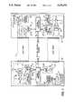
- FIG. 1is a block diagram of an identification friend-or-foe system according to one embodiment of the present invention.
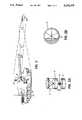
- FIG. 2is a prospective view illustrating the operation of the system shown in FIG. 1 with some components being shown in enlarged views in FIG. 2A and 2B.
- FIG. 1An Optical Identification Friend-or-Foe (OIFF) system according to the present invention is illustrated in FIG. 1 and consists of a unit 10 that is located on one land vehicle, i.e. tank 20 and an identical unit 10 located on another tank 20' as shown in FIG. 2.
- Each unit 10, 10'includes an infrared laser transmitter 1 located in a gunner's sight with a coder/modulator 2 connected to a laser diode 14.
- Coder/modulator 2is used to control and add predetermined codes to the emission from laser 14, which emission is transmitted through beam expanding optics 15 as a narrow beam along light path 11.
- a panoramic laser radiation detection unit 3including a detector 21 and an amplifier 22, is located on each tank 20 and is connected to a signal processor 7 which can identify predetermined codes in laser transmissions detected by unit 3.
- Each unit 10, 10'also includes a rotating retroreflector corner cube 4 with a coding mask 12 (FIG. 2A and 2B) installed in an aperture of retroreflector 4.
- Retroreflector 4is rotated by motor 5 under the control of a driver 16 which varies the rotational speed so that a predetermined code is added to any signal reflected by 4 back along light path 11'. Normally, the optical path to retroreflector 4 is blocked by an opaque cylinder 6 which surrounds retroreflector 4.
- a solenoid 17can raise cylinder 6 so that the optical path to retroreflector 4 is cleared. These are the positions of cylinders 6 shown in FIG. 1. Solenoid 17 is activated when a predetermined code is identified by processor 7 as being in a transmission detected by unit 3.
- the units 10also include a narrow field of view detection system 8, including a detector 23 and an amplifier 24, for detection of any signal reflected by retroreflector 4 back along light path 11'.
- Detection system 8is also connected to signal processor 7 where a predetermined code added by retroreflector 4 to a reflected signal can be identified. If that predetermined code is detected in a reflected signal by signal processor 7, the signal processor 7 sends a warning signal to the gunner and commander that a friendly tank is being engaged as well as a signal along cables 9 to a fire control system (not shown) which locks that fire control system to prevent that particular target from being engaged.
- each friendly tankbe equipped with a unit 10 or 10' with the operation of the system being illustrated in FIG. 2.
- the gunner in tank 20wants to engage a target, in this case tank 20', he first triggers a laser rangefinder to acquire range data for the fire-control system in tank 20.
- the OIFF laser transmitter 1is triggered to emit a series of coded laser pulses under the control of a coder or modulator 2 in order to transmit a pre-programmed code-of-the-day.
- the coded laser pulsesare collimated by lenses 15 so that they are transmitted in a narrow angular cone with an angle of ⁇ ° along light path 11.
- the emitted pulseswill irradiate only one target 20' of interest and not other targets that may be in the immediate surrounding area as a result of the narrow beam.
- the target 20'is an unfriendly one, one not equipped with an OIFF system 10
- only a diffuse reflection of the transmitted pulseswill be reflected back and picked up by the narrow field of view detection system 8, system 8 being also directed along the same light path 11.
- the transmitted coded pulseswill be detected by the target's own panoramic laser radiation detection unit 3 and analyzed by its signal processor 7 where a decision is made as to the validity of the transmitted code.
- the target's OIFF system 10'send a warning to its commander that an unfriendly laser transmission has been detected if, after analysis, it is determined that the received code bears little resemblance to a predetermined code-of-the day. However, steps are taken to respond to a friendly interrogating laser source if the signal processor determines that the detected laser code is in agreement with the pre-programmed code-of-the day.
- the steps taken to respond to a friendly interrogating laser transmitteris to first wait for a second transmission from the source 20 which will follow the first transmission after a preprogrammed known delay if the source is friendly.
- the signal processor 7, under control of the second transmission timing,will then clear the optical path to the rotating retroreflector corner cube 4 by activating the mechanical or electro-optical shutter 6. This will cause the second transmission to be strongly reflected back, in the form of a narrow beam, by reflector 4 along the light path 11' towards the source 20.
- a double modulationis added to the signal reflected back along light path 11' by retroreflector 4 which modulation can be analyzed by the source 20 of the laser transmissions.
- the first modulationis provided by a computer controlled motor driver 16 which controls the speed of rotation of retroreflector 4 in a programmable manner.
- the rotation of retroreflector 4acts as a light chopper on the laser beam being reflected such that the programmable speed of rotation will modulate the reflected beam with a predetermined code-of-the day.
- the second modulation of the reflected beamis produced by a mask 12 installed in the aperture of retroreflector 4. The mask 12, as shown in FIG.
- each tankwould have a different mask 12 installed in the aperture so that each mask 12 would provide a second modulation to the reflected beam which is specific to that tank and, as such, that modulation can be used to completely identify the particular tank which is being illuminated by the laser transmissions.
- the double modulated reflected beamcan then be picked-up by the narrow field of view detector 8 of the transmission source, i.e. tank 20 in FIG. 2, where the reflected beam is analyzed by a signal processor 7 and interpreted as the return of a beam reflected from a friendly tank 20'.
- the OIFF unit 10then immediately sends a warning to the gunner and commander of tank 20 that a friendly tank 20' is being engaged and, at the same time, the processing electronics locks the fire-control systems of tank 20 so that the target 20' cannot be fired upon.
- the laser transmitter 14is a solid-state laser of conventional design which preferably operates at an eye-safe laser wavelength, i.e. over 1.5 microns, and whose transmission is coded either by generating a sequence of pulses representing a binary code or by modulating the transmissions amplitude or pulse width with a pre-programmed information code.
- the laser transmittercan share the same beam expanding optics with the gunner's sight rangefinder to maintain the divergence of the laser transmission to an acceptable level or may have its own separate beam expanding optics 15.
- the laser transmittercould be separate from the rangefinder laser or the same laser could be operated for both purposes.
- the panoramic detection system 3may be an off-axis paraboloid mirror, an off-axis spheroid mirror or simply a section of a reflecting cone which concentrates energy from all over the horizon onto a single detector.
- the 360° field of view coveragemay be provided by four detectors, each covering a 90° field of view, arranged at right angles to each other so that no mirror is required.
- This panoramic detector assemblyis of a conventional design which is familiar to those skilled in the art.
- the mechanical or electro-optical shutter 6 in one preferred embodimentis an opaque cylinder which can be moved up or down by a solenoid 17 in order to clear or block an optical path to the rotating corner reflector 4.
- the optical transmission path to corner-reflector 4can be controlled using well known electro-optical techniques such as by using PLZT crystals.
- the rotating corner cube retroreflectorneeds to be located such that any interrogating beam is retroreflected to a transmitting source 20 for all azimuthal angles of arrival of transmissions from any transmitting sources.
- the rotating corner reflector cubeis, as a result, able to answer multiple friendly interrogations simultaneously.
- Modulation of the radiation reflected by the corner cube retroreflectoris obtained by varying its rate of rotation, the rotation being controlled by a computer controlled motor driver 16.
- the mask 12, which is installed in the aperture of the corner cube retroreflector to provide a second level of modulation to the reflected signal,can be simply a set of various width metal or plastic vertical bars directly glued onto the retroreflector. This second level of modulation provides a unique identification code for each target.
- the narrow field of view detector 8can share the same optics as the laser transmitter 1 by using a beam splitter or it can have its own optics of a conventional design. Alternatively, the narrow field of view detector 8 may be integrated in the gunner's sight where it would share the same optics as the rangefinder. In this last embodiment, the rangefinder detector can also be used as the narrow field of view detector.
- a military platform equipped with this type of OIFF systemwould be able to interrogate another, similarly equipped, one with a narrow coded laser beam which only irradiates a small target area so that the code could only become known to the target tank.
- the response code of the interrogated tankis completely passive, only reflecting an interrogation beam, and can become known only if the appropriate identification code has been received to unblock the transmission path to the retroreflector cube.
Landscapes
- Physics & Mathematics (AREA)
- Electromagnetism (AREA)
- Engineering & Computer Science (AREA)
- Computer Networks & Wireless Communication (AREA)
- General Physics & Mathematics (AREA)
- Radar, Positioning & Navigation (AREA)
- Remote Sensing (AREA)
- Signal Processing (AREA)
- Optical Radar Systems And Details Thereof (AREA)
Abstract
Description
The invention relates to interrogation-answering systems, in particular to battlefield identification friend-or-foe (IFF) systems, in which a transmitter in one vehicle transmits a coded signal to a target which responds with a signal after the target has analyzed the coded signal and verified, from the codes, that the transmitter is friendly.
One of the problems that face platform commanders on a modern land battlefield is to positively identify targets which are detected within range of their weapon systems. Detection is not only based on visual means, such as panoramic or telescopic sights, but is also considerably enhanced by using thermal imaging equipment. However, even with the most sophisticated thermal viewers, identification of land vehicles is not straightforward. The signatures of land vehicles detected by those types of thermal viewers are dependent, to a very large degree, on uncontrollable factors such as the time a vehicle's engine has been running, the time a vehicle has been exposed to direct sunlight, etc. Identification of friend-or-foe (IFF) presents a very difficult decision for a tank commander who must often decide in a split-second whether or not to engage a detected target while, at the same time, trying to minimize any possibility of fratricide killing.
No current systems exists which provide reliable, rapid and positive identification of friend-or-foe (IFF) vehicles on modern land battlefields. Commanders still rely on low-resolution visual and infrared images to determine if detected targets, be they tanks or other support vehicles, are enemy ones or not. That information may be possibly supported by information derived from a radio network. However, it is not always possible to obtain information from a radio since tank commanders often have to operate under radio silence in order to avoid being detected by the enemy.
A few techniques of IFF are known with one way to achieve an IFF function being for a vehicle, such as a tank, to carry a transponder that emits a coded return when a radar pulse is received by its receiver. This type of system is described in U.S. Pat. No. 4,851,849 by Otto Albersdoerfer. A similar type of system is described in U.S. Pat. No. 4,694,297 by Alan Sewards. However, the system in the U.S. Pat. No. 4,694,297 does not require an active transponder but only an antenna on a target vehicle which can re-radiate or reflect a radar beam and modulate that re-radiated beam in a distinctive manner. This system is based on the idea that an illuminating radar would detect only a small reflected signal from a good antenna which is terminated in a matched load. However, all of the energy intercepted by that antenna will be re-radiated when the antenna terminating impedance provides a short circuit. A substantial reflected signal is then created which may be detected by the source of the illuminating radar beam. Therefore, an antenna on a target vehicle with a variable terminating impedance can modulate a re-radiated radar beam to the source and provide an identification signal with the passively reflected beam.
A few other techniques (mainly Optical IFF) are known such as those described in German Patents 2,215,463 (Precitronic Feinmech); 2,142,944 (Precintronic Ges Feinmech); 3,323,698 (Ant. Machr Ichtentech) and 3,113,154 (Precitronic Ges FEI). IFF systems are also described in French Patent 2,605,416 by Joquiet J. C. and U.S. Pat. No. 4,814,769 by Leon Robin et al.
The present invention generally falls into the Optical IFF (OIFF) category but, although based on a similar principle of operation, differs markedly from the prior art in the means used. Many of the techniques in the prior art give rise to very complex systems and their coding techniques are much less secure than those according to the present invention.
An identification friend-or-foe (IFF) system for vehicles, according to one embodiment of the present invention, requires that a radiation transmitter and a receiver for detecting radiation transmitted by other vehicles be located on each vehicle with each receiver having a means to detect and identify a first coded signal transmitted by transmitters on other vehicles and a means to provide an unblocking signal to a means to clear a radiation transmission path in the vehicle, the path containing a reflector to reflect a received signal after a predetermined code is identified and the path unblocked by said unblocking signal, the reflector including means to add a further predetermined code to a signal reflected from the reflector with each vehicle having a further means to detect the reflected signal.
The following detailed description of the invention will be more readily understood when considered in conjunction with the accompanying drawings, in which
FIG. 1 is a block diagram of an identification friend-or-foe system according to one embodiment of the present invention, and
FIG. 2 is a prospective view illustrating the operation of the system shown in FIG. 1 with some components being shown in enlarged views in FIG. 2A and 2B.
An Optical Identification Friend-or-Foe (OIFF) system according to the present invention is illustrated in FIG. 1 and consists of aunit 10 that is located on one land vehicle, i.e.tank 20 and anidentical unit 10 located on another tank 20' as shown in FIG. 2. Eachunit infrared laser transmitter 1 located in a gunner's sight with a coder/modulator 2 connected to alaser diode 14. Coder/modulator 2 is used to control and add predetermined codes to the emission fromlaser 14, which emission is transmitted throughbeam expanding optics 15 as a narrow beam along light path 11. A panoramic laser radiation detection unit 3, including adetector 21 and anamplifier 22, is located on eachtank 20 and is connected to asignal processor 7 which can identify predetermined codes in laser transmissions detected by unit 3. Eachunit retroreflector corner cube 4 with a coding mask 12 (FIG. 2A and 2B) installed in an aperture ofretroreflector 4. Retroreflector 4 is rotated bymotor 5 under the control of adriver 16 which varies the rotational speed so that a predetermined code is added to any signal reflected by 4 back along light path 11'. Normally, the optical path toretroreflector 4 is blocked by anopaque cylinder 6 which surroundsretroreflector 4. However, a solenoid 17 can raisecylinder 6 so that the optical path toretroreflector 4 is cleared. These are the positions ofcylinders 6 shown in FIG. 1. Solenoid 17 is activated when a predetermined code is identified byprocessor 7 as being in a transmission detected by unit 3.
Theunits 10 also include a narrow field ofview detection system 8, including adetector 23 and anamplifier 24, for detection of any signal reflected byretroreflector 4 back along light path 11'.Detection system 8 is also connected tosignal processor 7 where a predetermined code added byretroreflector 4 to a reflected signal can be identified. If that predetermined code is detected in a reflected signal bysignal processor 7, thesignal processor 7 sends a warning signal to the gunner and commander that a friendly tank is being engaged as well as a signal alongcables 9 to a fire control system (not shown) which locks that fire control system to prevent that particular target from being engaged.
Operation of the OIFF system requires that each friendly tank be equipped with aunit tank 20 wants to engage a target, in this case tank 20', he first triggers a laser rangefinder to acquire range data for the fire-control system intank 20. Immediately after the rangefinder pulse has been emitted, or at the same time, the OIFFlaser transmitter 1 is triggered to emit a series of coded laser pulses under the control of a coder ormodulator 2 in order to transmit a pre-programmed code-of-the-day. The coded laser pulses are collimated bylenses 15 so that they are transmitted in a narrow angular cone with an angle of Θ° along light path 11. The emitted pulses will irradiate only one target 20' of interest and not other targets that may be in the immediate surrounding area as a result of the narrow beam. In the case when the target 20' is an unfriendly one, one not equipped with anOIFF system 10,, only a diffuse reflection of the transmitted pulses will be reflected back and picked up by the narrow field ofview detection system 8,system 8 being also directed along the same light path 11. In the case of a friendly target, which is one provided withsimilar OIFF system 10', the transmitted coded pulses will be detected by the target's own panoramic laser radiation detection unit 3 and analyzed by itssignal processor 7 where a decision is made as to the validity of the transmitted code. The target'sOIFF system 10' send a warning to its commander that an unfriendly laser transmission has been detected if, after analysis, it is determined that the received code bears little resemblance to a predetermined code-of-the day. However, steps are taken to respond to a friendly interrogating laser source if the signal processor determines that the detected laser code is in agreement with the pre-programmed code-of-the day.
The steps taken to respond to a friendly interrogating laser transmitter is to first wait for a second transmission from thesource 20 which will follow the first transmission after a preprogrammed known delay if the source is friendly. Thesignal processor 7, under control of the second transmission timing, will then clear the optical path to the rotatingretroreflector corner cube 4 by activating the mechanical or electro-optical shutter 6. This will cause the second transmission to be strongly reflected back, in the form of a narrow beam, byreflector 4 along the light path 11' towards thesource 20.
A double modulation is added to the signal reflected back along light path 11' byretroreflector 4 which modulation can be analyzed by thesource 20 of the laser transmissions. The first modulation is provided by a computer controlledmotor driver 16 which controls the speed of rotation ofretroreflector 4 in a programmable manner. The rotation ofretroreflector 4 acts as a light chopper on the laser beam being reflected such that the programmable speed of rotation will modulate the reflected beam with a predetermined code-of-the day. The second modulation of the reflected beam is produced by amask 12 installed in the aperture ofretroreflector 4. Themask 12, as shown in FIG. 2B, consists of a series of vertical bars of varied widths and/or spacing which act as small light chopper blades on the laser beam reflected by therotating retroreflector 4. Each tank would have adifferent mask 12 installed in the aperture so that eachmask 12 would provide a second modulation to the reflected beam which is specific to that tank and, as such, that modulation can be used to completely identify the particular tank which is being illuminated by the laser transmissions.
The double modulated reflected beam can then be picked-up by the narrow field ofview detector 8 of the transmission source, i.e.tank 20 in FIG. 2, where the reflected beam is analyzed by asignal processor 7 and interpreted as the return of a beam reflected from a friendly tank 20'. TheOIFF unit 10 then immediately sends a warning to the gunner and commander oftank 20 that a friendly tank 20' is being engaged and, at the same time, the processing electronics locks the fire-control systems oftank 20 so that the target 20' cannot be fired upon.
In a preferred embodiment, thelaser transmitter 14 is a solid-state laser of conventional design which preferably operates at an eye-safe laser wavelength, i.e. over 1.5 microns, and whose transmission is coded either by generating a sequence of pulses representing a binary code or by modulating the transmissions amplitude or pulse width with a pre-programmed information code. The laser transmitter can share the same beam expanding optics with the gunner's sight rangefinder to maintain the divergence of the laser transmission to an acceptable level or may have its own separatebeam expanding optics 15. The laser transmitter could be separate from the rangefinder laser or the same laser could be operated for both purposes.
The panoramic detection system 3 may be an off-axis paraboloid mirror, an off-axis spheroid mirror or simply a section of a reflecting cone which concentrates energy from all over the horizon onto a single detector. In an even simpler approach, the 360° field of view coverage may be provided by four detectors, each covering a 90° field of view, arranged at right angles to each other so that no mirror is required. This panoramic detector assembly is of a conventional design which is familiar to those skilled in the art.
The mechanical or electro-optical shutter 6 in one preferred embodiment is an opaque cylinder which can be moved up or down by a solenoid 17 in order to clear or block an optical path to therotating corner reflector 4. In other embodiments, the optical transmission path to corner-reflector 4 can be controlled using well known electro-optical techniques such as by using PLZT crystals.
The rotating corner cube retroreflector needs to be located such that any interrogating beam is retroreflected to a transmittingsource 20 for all azimuthal angles of arrival of transmissions from any transmitting sources. The rotating corner reflector cube is, as a result, able to answer multiple friendly interrogations simultaneously. Modulation of the radiation reflected by the corner cube retroreflector is obtained by varying its rate of rotation, the rotation being controlled by a computer controlledmotor driver 16. Themask 12, which is installed in the aperture of the corner cube retroreflector to provide a second level of modulation to the reflected signal, can be simply a set of various width metal or plastic vertical bars directly glued onto the retroreflector. This second level of modulation provides a unique identification code for each target.
The narrow field ofview detector 8 can share the same optics as thelaser transmitter 1 by using a beam splitter or it can have its own optics of a conventional design. Alternatively, the narrow field ofview detector 8 may be integrated in the gunner's sight where it would share the same optics as the rangefinder. In this last embodiment, the rangefinder detector can also be used as the narrow field of view detector.
A military platform equipped with this type of OIFF system would be able to interrogate another, similarly equipped, one with a narrow coded laser beam which only irradiates a small target area so that the code could only become known to the target tank. The response code of the interrogated tank is completely passive, only reflecting an interrogation beam, and can become known only if the appropriate identification code has been received to unblock the transmission path to the retroreflector cube. These features optimize security for the OIFF system.
Various modifications may be made to the preferred embodiments without departing from the spirit and scope of the invention as defined in the appended claims.
Claims (19)
1. An identification friend-or-foe system for vehicles comprising, in each vehicle, a narrow-beam radiation transmitter and a receiver with a panoramic detection means for detecting radiation transmitted by other vehicles from any direction around the horizon, the transmitter having a means for transmitting a first coded signal, and the receiver comprising a reflector, blocking means, having a blocking mode in which said blocking means completely encircles said reflector, for, in said blocking mode, blocking transmission to said reflector, and means for detecting and identifying the first coded signal transmitted by other vehicles and for, responsive thereto, providing an unblocking signal to the blocking means so as to clear a radiation transmission path completely around the reflector so that the reflector reflects a received signal received from any direction around the horizon after a predetermined code is identified and the transmission path is cleared responsive to said unblocking signal, the reflector comprising a continuously rotating retroreflector that reflects a signal received from any direction around the horizon back in that direction and said retroreflector including means for adding a further predetermined code to a signal reflected from said retroreflector, each vehicle including a further means directed in the same direction as the radiation transmitter for detecting a reflected signal.
2. A system as defined in claim 1, wherein the radiation transmitter is a laser that transmits a narrow beam.
3. A system as defined in claim 2, wherein the detection means is a panoramic laser radiation detection unit.
4. A system as defined in claim 3, wherein said further means is a narrow field of view detector for the reflected signal.
5. A system as defined in claim 4, wherein the detection means comprises a reflector having the shape of a section of a cone which reflects radiation from all over the horizon onto a single detector.
6. A system as defined in claim 4, wherein the detection means is a paraboloid mirror which reflects radiation onto a detector.
7. A system as defined in claim 4, wherein the detection means is a spheroid mirror reflecting light onto a detector.
8. A system as defined in claim 4, wherein the detection means comprises four 90° field of view detectors arranged to cover a 360° field of view.
9. A system as defined in claim 4, wherein the rotating retroreflector is a rotating corner cube retroreflector provided with a computer controlled motor drive which adds said further pre-determined code to the reflected signal by varying the speed of rotation.
10. A system as defined in claim 9, wherein a mask is installed in an aperture of the rotating corner cube retroreflector, the mask providing a second level of modulation to the reflected signal.
11. A system as defined in claim 10, wherein apertures in the mask are formed by spaced apart vertical bars which provide said second level of modulation.
12. A system as defined in claim 4, wherein the rotating retroreflector is a rotating corner cube retroreflector and the means to clear a radiation transmission path is a movable opaque cylinder surrounding the retroreflector and a solenoid to move the cylinder away from the retroreflector.
13. A system as defined in claim 4, wherein the rotating retroreflector is a rotating corner cube retroreflector and the means to clear a radiation transmission path is an electro-optical shutter.
14. A system as defined in claim 4, wherein the vehicles are provided with a fire-control system for a gunner including a laser rangefinder.
15. A system as defined in claim 14, wherein the narrow field of view detector is connected to a signal processor which identifies codes in a reflected signal and locks the fire-control system when the further predetermined code is detected.
16. A system as defined in claim 4, wherein the vehicles are provided with a fire-control system for a gunner including a laser rangefinder that shares beam expanding optics with the radiation transmitter.
17. A system as defined in claim 4, wherein the laser transmitter and the narrow field of view detector share the same optics through a beam splitter.
18. A system as defined in claim 16, wherein the narrow field of view detector is connected to a signal processor which identifies codes in a reflected signal and locks the fire-control system when the further predetermined code is detected.
19. A system as defined in claim 17 wherein the narrow field of view detector is connected to a signal processor which identifies codes in a reflected signal and locks a fire-control system when the further predetermined code is detected.
Applications Claiming Priority (2)
| Application Number | Priority Date | Filing Date | Title |
|---|---|---|---|
| CA2055198 | 1991-11-08 | ||
| CA002055198ACA2055198A1 (en) | 1991-11-08 | 1991-11-08 | Optical identification friend-or-foe |
Publications (1)
| Publication Number | Publication Date |
|---|---|
| US5274379Atrue US5274379A (en) | 1993-12-28 |
Family
ID=4148724
Family Applications (1)
| Application Number | Title | Priority Date | Filing Date |
|---|---|---|---|
| US07/915,302Expired - Fee RelatedUS5274379A (en) | 1991-11-08 | 1992-07-20 | Optical identification friend-or-foe |
Country Status (2)
| Country | Link |
|---|---|
| US (1) | US5274379A (en) |
| CA (1) | CA2055198A1 (en) |
Cited By (75)
| Publication number | Priority date | Publication date | Assignee | Title |
|---|---|---|---|---|
| US5355241A (en)* | 1991-12-09 | 1994-10-11 | Kelley Clifford W | Identification friend or foe discriminator |
| US5396243A (en)* | 1992-12-23 | 1995-03-07 | The United States Of America As Represented By The Secretary Of The Air Force | Infrared laser battlefield identification beacon |
| US5422645A (en)* | 1994-02-14 | 1995-06-06 | The United States Of America As Represented By The Secretary Of The Army | Delayed laser retroreflector pulse technique and system |
| US5459470A (en)* | 1992-04-01 | 1995-10-17 | Electronics & Space Corp. | Beam steered laser IFF system |
| WO1995034922A1 (en)* | 1994-06-16 | 1995-12-21 | Hann Lenn R | Method and apparatus for modulating a doppler radar signal |
| US5539565A (en)* | 1995-09-27 | 1996-07-23 | Motorola, Inc. | Method and apparatus for a selective optical retroreflector |
| US5686722A (en)* | 1996-02-28 | 1997-11-11 | Her Majesty The Queen In Right Of Canada, As Represented By The Minister Of National Defence Of Her Majesty's Canadian Government | Selective wavelength identification friend or foe (SWIFF) |
| US5748138A (en)* | 1996-09-30 | 1998-05-05 | Telle; John M. | Synchronous identification of friendly targets |
| US5767802A (en)* | 1997-01-10 | 1998-06-16 | Northrop Grumman Corporation | IFF system including a low radar cross-section synthetic aperture radar (SAR) |
| US5796362A (en)* | 1994-06-13 | 1998-08-18 | Hittite Microwave Corporation | Post launch on-board identification friend or foe system |
| US5819164A (en)* | 1996-01-29 | 1998-10-06 | The United States Of America As Represented By The Secretary Of The Army | Modulated retroreflection system for secure communication and identification |
| US5966227A (en)* | 1996-11-01 | 1999-10-12 | Her Majesty The Queen In Right Of Canada, As Represented By The Minister Of National Defence | Active cooperative tuned identification friend or foe (ACTIFF) |
| US6057520A (en)* | 1999-06-30 | 2000-05-02 | Mcnc | Arc resistant high voltage micromachined electrostatic switch |
| US6097330A (en)* | 1993-01-19 | 2000-08-01 | Itt Corporation | Optical friendly fire avoidance system |
| US6100840A (en)* | 1998-08-26 | 2000-08-08 | Spectra Research, Inc. | Radio frequency tag system |
| US6137623A (en)* | 1998-03-17 | 2000-10-24 | Mcnc | Modulatable reflectors and methods for using same |
| US6229683B1 (en) | 1999-06-30 | 2001-05-08 | Mcnc | High voltage micromachined electrostatic switch |
| US6236491B1 (en) | 1999-05-27 | 2001-05-22 | Mcnc | Micromachined electrostatic actuator with air gap |
| US6275320B1 (en) | 1999-09-27 | 2001-08-14 | Jds Uniphase, Inc. | MEMS variable optical attenuator |
| WO2002096015A1 (en)* | 2001-05-21 | 2002-11-28 | Nanochron, Llc | Optical device for identifying friends and foes using real-time optical encryption and method for producing the same |
| US6586738B2 (en) | 2001-04-13 | 2003-07-01 | Mcnc | Electromagnetic radiation detectors having a micromachined electrostatic chopper device |
| US20030147651A1 (en)* | 2002-02-01 | 2003-08-07 | Roes John B. | Secure covert combat identification friend-or-foe (IFF) system for the dismounted soldier |
| US20040046123A1 (en)* | 2001-04-13 | 2004-03-11 | Mcnc Research And Development Institute | Electromagnetic radiation detectors having a microelectromechanical shutter device |
| US20040068651A1 (en)* | 2002-05-21 | 2004-04-08 | Pender Michael J. | Optical device for identifying friends and foes using real-time optical encryption and method for producing the same |
| US20050105914A1 (en)* | 2003-11-17 | 2005-05-19 | Chen Chungte W. | Method for identifying an interrogated object using a dynamic optical tag identification system |
| US20060003701A1 (en)* | 2004-06-30 | 2006-01-05 | Daoud Bassel H | Alignment system for communications |
| US20070236384A1 (en)* | 2006-02-12 | 2007-10-11 | Gennadii Ivtsenkov | Cost-effective friend-or-foe (IFF) combat infrared alert and identification system (CID) |
| US20070278391A1 (en)* | 2003-07-18 | 2007-12-06 | Honeywell International Inc. | Method for Targeting a Source of an Incoming Laser |
| US20090010644A1 (en)* | 2002-02-01 | 2009-01-08 | Cubic Corporation | Integrated optical communication and range finding system and applications thereof |
| US20090045996A1 (en)* | 2007-03-13 | 2009-02-19 | Gennadii Ivtsenkov | Combined IR-RF combat identification friend-or-foe (IFF) system for the dismounted soldier |
| US20090074422A1 (en)* | 2007-07-20 | 2009-03-19 | Jerry Stewart | Methods and Apparatus for Target Identification |
| US20090079616A1 (en)* | 2007-09-20 | 2009-03-26 | Lockheed Martin Corporation | Covert long range positive friendly identification system |
| US20090116850A1 (en)* | 2007-10-29 | 2009-05-07 | Cubic Corporation | Resonant quantum well modulator driver |
| US20090116025A1 (en)* | 2007-11-06 | 2009-05-07 | Cubic Corporation | Field test of a retro-reflector and detector assembly |
| US20090202254A1 (en)* | 2008-02-12 | 2009-08-13 | Arun Kumar Majumdar | Wide field-of-view amplified fiber-retro for secure high data rate communications and remote data transfer |
| US20100135670A1 (en)* | 2008-11-21 | 2010-06-03 | Cubic Corporation | Phase-modulating communication device |
| US20100277364A1 (en)* | 2006-06-20 | 2010-11-04 | Telespazio S.P.A. | Target identification method for a synthetic aperature radar system |
| US20110036983A1 (en)* | 2007-11-27 | 2011-02-17 | Ford Timothy D F | Identification system and method using highly collimated source of electromagnetic radiation |
| US8051597B1 (en) | 2007-06-14 | 2011-11-08 | Cubic Corporation | Scout sniper observation scope |
| US20120098693A1 (en)* | 2009-07-28 | 2012-04-26 | Timothy Bradley | Scene illuminator |
| US8224189B1 (en) | 2007-02-02 | 2012-07-17 | Sunlight Photonics Inc. | Retro-directive target for free-space optical communication and method of producing the same |
| US20120189312A1 (en)* | 2010-07-19 | 2012-07-26 | Cubic Corporation | Near field combat identification |
| US20130176570A1 (en)* | 2012-01-11 | 2013-07-11 | The Aerospace Corporation | System, Apparatus, and Method for Tracking Atmospheric Differential Absorption |
| US9068798B2 (en) | 2010-07-19 | 2015-06-30 | Cubic Corporation | Integrated multifunction scope for optical combat identification and other uses |
| EP2990840A1 (en)* | 2014-08-29 | 2016-03-02 | Thales | System for detecting posture with a retroreflector comprising a wire mesh |
| US20160285551A1 (en)* | 2015-03-24 | 2016-09-29 | The United States Of America As Represented By The Secretary Of The Navy | Methods and systems for identification and communication using free space optical systems including wearable systems |
| US9519853B2 (en) | 2013-11-01 | 2016-12-13 | James P Tolle | Wearable, non-visible identification device for friendly force identification and intruder detection |
| US20170146659A1 (en)* | 2014-06-12 | 2017-05-25 | Terabee S.A.S. | Dynamic Tracking System and Automatic Guidance Method Based on 3D Time-of-Flight Cameras |
| US20170343671A1 (en)* | 2016-05-24 | 2017-11-30 | Autoliv Asp, Inc. | Direct Detection LiDAR System and Method with Pulse Amplitude Modulation (AM) Transmitter and Quadrature Receiver |
| WO2018057657A3 (en)* | 2016-09-20 | 2018-05-11 | Apple Inc. | Retroreflectors |
| US10270528B1 (en)* | 2016-06-30 | 2019-04-23 | Google Llc | Serial communication to device through lighting control |
| US10416292B2 (en) | 2016-05-24 | 2019-09-17 | Veoneer Us, Inc. | Direct detection LiDAR system and method with frequency modulation (FM) transmitter and quadrature receiver |
| US10473784B2 (en) | 2016-05-24 | 2019-11-12 | Veoneer Us, Inc. | Direct detection LiDAR system and method with step frequency modulation (FM) pulse-burst envelope modulation transmission and quadrature demodulation |
| CN110492936A (en)* | 2019-08-08 | 2019-11-22 | Oppo广东移动通信有限公司 | Addition good friend method, apparatus and mobile terminal based on visible light communication |
| US10613200B2 (en) | 2017-09-19 | 2020-04-07 | Veoneer, Inc. | Scanning lidar system and method |
| US10684370B2 (en) | 2017-09-29 | 2020-06-16 | Veoneer Us, Inc. | Multifunction vehicle detection system |
| US10782400B2 (en)* | 2015-10-11 | 2020-09-22 | Israel Aerospace Industries Ltd. | Identification friend or foe (IFF) system and method |
| US10838043B2 (en) | 2017-11-15 | 2020-11-17 | Veoneer Us, Inc. | Scanning LiDAR system and method with spatial filtering for reduction of ambient light |
| US10880035B2 (en) | 2009-07-28 | 2020-12-29 | The United States Of America, As Represented By The Secretary Of The Navy | Unauthorized electro-optics (EO) device detection and response system |
| US11047984B2 (en)* | 2015-05-18 | 2021-06-29 | Arcachon Holdings Llc | System, method, and apparatus for synchronizing local flashing in a marker system |
| US11092478B2 (en) | 2017-08-02 | 2021-08-17 | X-Beamer Technologies Ltd. | Retro-reflective interferometer |
| US11194022B2 (en) | 2017-09-29 | 2021-12-07 | Veoneer Us, Inc. | Detection system with reflection member and offset detection array |
| US11313969B2 (en) | 2019-10-28 | 2022-04-26 | Veoneer Us, Inc. | LiDAR homodyne transceiver using pulse-position modulation |
| US11326758B1 (en) | 2021-03-12 | 2022-05-10 | Veoneer Us, Inc. | Spotlight illumination system using optical element |
| US11460550B2 (en) | 2017-09-19 | 2022-10-04 | Veoneer Us, Llc | Direct detection LiDAR system and method with synthetic doppler processing |
| US11474218B2 (en) | 2019-07-15 | 2022-10-18 | Veoneer Us, Llc | Scanning LiDAR system and method with unitary optical element |
| RU2787082C2 (en)* | 2017-12-08 | 2022-12-28 | Велодайн Лидар, Инк | Systems and methods for improvement of detection of echo signal in optical ranging and detection system |
| US11579257B2 (en) | 2019-07-15 | 2023-02-14 | Veoneer Us, Llc | Scanning LiDAR system and method with unitary optical element |
| US11585901B2 (en) | 2017-11-15 | 2023-02-21 | Veoneer Us, Llc | Scanning lidar system and method with spatial filtering for reduction of ambient light |
| US11732858B2 (en) | 2021-06-18 | 2023-08-22 | Veoneer Us, Llc | Headlight illumination system using optical element |
| US11771164B2 (en) | 2015-05-18 | 2023-10-03 | Arcachon Holdings Llc | System, method, and apparatus for synchronizing local flashing in a marker system |
| US12044800B2 (en) | 2021-01-14 | 2024-07-23 | Magna Electronics, Llc | Scanning LiDAR system and method with compensation for transmit laser pulse effects |
| US12092278B2 (en) | 2022-10-07 | 2024-09-17 | Magna Electronics, Llc | Generating a spotlight |
| US12202396B1 (en) | 2023-12-19 | 2025-01-21 | Magna Electronics, Llc | Line-scan-gated imaging for LiDAR headlight |
| US12228653B2 (en) | 2022-10-07 | 2025-02-18 | Magna Electronics, Llc | Integrating a sensing system into headlight optics |
Citations (17)
| Publication number | Priority date | Publication date | Assignee | Title |
|---|---|---|---|---|
| DE2142944A1 (en)* | 1971-08-27 | 1973-03-08 | Precitronic | FRIEND / ENEMY IDENTIFICATION SYSTEM AND AUTOMATIC WEAPON SECURITY OR - RELEASE DEVICE FOR THE AREA OF OPTICAL VIEW IN CONNECTION WITH A COMMUNICATION DEVICE |
| US3721950A (en)* | 1969-08-13 | 1973-03-20 | Sanders Associates Inc | Responsive navigation beacon |
| DE2215463A1 (en)* | 1972-03-29 | 1973-10-11 | Precitronic | IDENTIFICATION AND SIGNAL TRANSMISSION SYSTEM FOR FRIENDS / FEMESE DETECTION USING LASER LIGHT VIA ROOM-STABILIZED EQUIPMENT |
| US3989942A (en)* | 1974-12-13 | 1976-11-02 | International Telephone And Telegraph Corporation | Retro-reflecting laser responser and data modulator |
| US4134008A (en)* | 1977-01-25 | 1979-01-09 | Thomson-Csf | Light retro-reflecting responser and data modulator arrangement |
| US4143263A (en)* | 1974-11-08 | 1979-03-06 | Kurt Eichweber | Receiver-transmitter device for transmitting data by means of focused modulated, light beams |
| US4249265A (en)* | 1978-10-06 | 1981-02-03 | Societe Anonyme De Telecommunications | Device for receiving and transmitting coded light signals and IFF system incorporating this device |
| US4361911A (en)* | 1981-05-21 | 1982-11-30 | The United States Of American As Represented By The Secretary Of The Army | Laser retroreflector system for identification of friend or foe |
| DE3113154A1 (en)* | 1981-04-01 | 1982-12-02 | Precitronic Gesellschaft für Feinmechanik und Electronic mbH, 2000 Hamburg | System for optronic data input in laser communications devices |
| DE3323698A1 (en)* | 1983-07-01 | 1985-01-03 | ANT Nachrichtentechnik GmbH, 7150 Backnang | Method for identifying devices |
| GB2186457A (en)* | 1984-10-18 | 1987-08-12 | Gec Avionics | Optical communications |
| US4694297A (en)* | 1984-02-27 | 1987-09-15 | Her Majesty The Queen In Right Of Canada, As Represented By The Minister Of National Defence | Remote identification device |
| US4731879A (en)* | 1983-08-05 | 1988-03-15 | Messerschmitt-Boelkow-Blohm Gmbh | Remote data monitoring system |
| FR2605416A1 (en)* | 1986-10-15 | 1988-04-22 | Lmt Radio Professionelle | BATTLEFIELD IFF IDENTIFICATION METHOD AND IFF IMPLEMENTATION SYSTEM |
| US4763361A (en)* | 1986-02-13 | 1988-08-09 | The United States Of America As Represented By The Secretary Of The Army | System and device for recognition or IFF use |
| US4814769A (en)* | 1984-12-14 | 1989-03-21 | Thomson - Csf | Friend-foe interrogation method and a system using this method |
| US4851849A (en)* | 1973-11-09 | 1989-07-25 | Siemens Aktiengesellschaft | Interrogation-answering system with a primary radar |
- 1991
- 1991-11-08CACA002055198Apatent/CA2055198A1/ennot_activeAbandoned
- 1992
- 1992-07-20USUS07/915,302patent/US5274379A/ennot_activeExpired - Fee Related
Patent Citations (17)
| Publication number | Priority date | Publication date | Assignee | Title |
|---|---|---|---|---|
| US3721950A (en)* | 1969-08-13 | 1973-03-20 | Sanders Associates Inc | Responsive navigation beacon |
| DE2142944A1 (en)* | 1971-08-27 | 1973-03-08 | Precitronic | FRIEND / ENEMY IDENTIFICATION SYSTEM AND AUTOMATIC WEAPON SECURITY OR - RELEASE DEVICE FOR THE AREA OF OPTICAL VIEW IN CONNECTION WITH A COMMUNICATION DEVICE |
| DE2215463A1 (en)* | 1972-03-29 | 1973-10-11 | Precitronic | IDENTIFICATION AND SIGNAL TRANSMISSION SYSTEM FOR FRIENDS / FEMESE DETECTION USING LASER LIGHT VIA ROOM-STABILIZED EQUIPMENT |
| US4851849A (en)* | 1973-11-09 | 1989-07-25 | Siemens Aktiengesellschaft | Interrogation-answering system with a primary radar |
| US4143263A (en)* | 1974-11-08 | 1979-03-06 | Kurt Eichweber | Receiver-transmitter device for transmitting data by means of focused modulated, light beams |
| US3989942A (en)* | 1974-12-13 | 1976-11-02 | International Telephone And Telegraph Corporation | Retro-reflecting laser responser and data modulator |
| US4134008A (en)* | 1977-01-25 | 1979-01-09 | Thomson-Csf | Light retro-reflecting responser and data modulator arrangement |
| US4249265A (en)* | 1978-10-06 | 1981-02-03 | Societe Anonyme De Telecommunications | Device for receiving and transmitting coded light signals and IFF system incorporating this device |
| DE3113154A1 (en)* | 1981-04-01 | 1982-12-02 | Precitronic Gesellschaft für Feinmechanik und Electronic mbH, 2000 Hamburg | System for optronic data input in laser communications devices |
| US4361911A (en)* | 1981-05-21 | 1982-11-30 | The United States Of American As Represented By The Secretary Of The Army | Laser retroreflector system for identification of friend or foe |
| DE3323698A1 (en)* | 1983-07-01 | 1985-01-03 | ANT Nachrichtentechnik GmbH, 7150 Backnang | Method for identifying devices |
| US4731879A (en)* | 1983-08-05 | 1988-03-15 | Messerschmitt-Boelkow-Blohm Gmbh | Remote data monitoring system |
| US4694297A (en)* | 1984-02-27 | 1987-09-15 | Her Majesty The Queen In Right Of Canada, As Represented By The Minister Of National Defence | Remote identification device |
| GB2186457A (en)* | 1984-10-18 | 1987-08-12 | Gec Avionics | Optical communications |
| US4814769A (en)* | 1984-12-14 | 1989-03-21 | Thomson - Csf | Friend-foe interrogation method and a system using this method |
| US4763361A (en)* | 1986-02-13 | 1988-08-09 | The United States Of America As Represented By The Secretary Of The Army | System and device for recognition or IFF use |
| FR2605416A1 (en)* | 1986-10-15 | 1988-04-22 | Lmt Radio Professionelle | BATTLEFIELD IFF IDENTIFICATION METHOD AND IFF IMPLEMENTATION SYSTEM |
Cited By (116)
| Publication number | Priority date | Publication date | Assignee | Title |
|---|---|---|---|---|
| US5355241A (en)* | 1991-12-09 | 1994-10-11 | Kelley Clifford W | Identification friend or foe discriminator |
| US5459470A (en)* | 1992-04-01 | 1995-10-17 | Electronics & Space Corp. | Beam steered laser IFF system |
| US5396243A (en)* | 1992-12-23 | 1995-03-07 | The United States Of America As Represented By The Secretary Of The Air Force | Infrared laser battlefield identification beacon |
| US6097330A (en)* | 1993-01-19 | 2000-08-01 | Itt Corporation | Optical friendly fire avoidance system |
| US5422645A (en)* | 1994-02-14 | 1995-06-06 | The United States Of America As Represented By The Secretary Of The Army | Delayed laser retroreflector pulse technique and system |
| US5796362A (en)* | 1994-06-13 | 1998-08-18 | Hittite Microwave Corporation | Post launch on-board identification friend or foe system |
| WO1995034922A1 (en)* | 1994-06-16 | 1995-12-21 | Hann Lenn R | Method and apparatus for modulating a doppler radar signal |
| US5508704A (en)* | 1994-06-16 | 1996-04-16 | Hann; Lenn R. | Method and apparatus for modulating a doppler radar signal |
| US5539565A (en)* | 1995-09-27 | 1996-07-23 | Motorola, Inc. | Method and apparatus for a selective optical retroreflector |
| US5819164A (en)* | 1996-01-29 | 1998-10-06 | The United States Of America As Represented By The Secretary Of The Army | Modulated retroreflection system for secure communication and identification |
| US5686722A (en)* | 1996-02-28 | 1997-11-11 | Her Majesty The Queen In Right Of Canada, As Represented By The Minister Of National Defence Of Her Majesty's Canadian Government | Selective wavelength identification friend or foe (SWIFF) |
| US5748138A (en)* | 1996-09-30 | 1998-05-05 | Telle; John M. | Synchronous identification of friendly targets |
| US5966227A (en)* | 1996-11-01 | 1999-10-12 | Her Majesty The Queen In Right Of Canada, As Represented By The Minister Of National Defence | Active cooperative tuned identification friend or foe (ACTIFF) |
| US5767802A (en)* | 1997-01-10 | 1998-06-16 | Northrop Grumman Corporation | IFF system including a low radar cross-section synthetic aperture radar (SAR) |
| US6233088B1 (en) | 1998-03-17 | 2001-05-15 | Mcnc | Methods for modulating a radiation signal |
| US6137623A (en)* | 1998-03-17 | 2000-10-24 | Mcnc | Modulatable reflectors and methods for using same |
| US6100840A (en)* | 1998-08-26 | 2000-08-08 | Spectra Research, Inc. | Radio frequency tag system |
| US6236491B1 (en) | 1999-05-27 | 2001-05-22 | Mcnc | Micromachined electrostatic actuator with air gap |
| US6229683B1 (en) | 1999-06-30 | 2001-05-08 | Mcnc | High voltage micromachined electrostatic switch |
| US6057520A (en)* | 1999-06-30 | 2000-05-02 | Mcnc | Arc resistant high voltage micromachined electrostatic switch |
| US6275320B1 (en) | 1999-09-27 | 2001-08-14 | Jds Uniphase, Inc. | MEMS variable optical attenuator |
| US6586738B2 (en) | 2001-04-13 | 2003-07-01 | Mcnc | Electromagnetic radiation detectors having a micromachined electrostatic chopper device |
| US7026602B2 (en) | 2001-04-13 | 2006-04-11 | Research Triangle Institute | Electromagnetic radiation detectors having a microelectromechanical shutter device |
| US20040046123A1 (en)* | 2001-04-13 | 2004-03-11 | Mcnc Research And Development Institute | Electromagnetic radiation detectors having a microelectromechanical shutter device |
| WO2002096015A1 (en)* | 2001-05-21 | 2002-11-28 | Nanochron, Llc | Optical device for identifying friends and foes using real-time optical encryption and method for producing the same |
| US20040028357A1 (en)* | 2001-05-21 | 2004-02-12 | Pender Michael J. | Optical matrix photonic logic device and method for producing the same |
| US7720388B2 (en)* | 2002-02-01 | 2010-05-18 | Cubic Corporation | Integrated optical communication and range finding system and application thereof |
| US20090142053A1 (en)* | 2002-02-01 | 2009-06-04 | Cubic Corporation | Integrated optical communication and range finding system and application thereof |
| US20030147651A1 (en)* | 2002-02-01 | 2003-08-07 | Roes John B. | Secure covert combat identification friend-or-foe (IFF) system for the dismounted soldier |
| US7983565B2 (en)* | 2002-02-01 | 2011-07-19 | Cubic Corporation | Integrated optical communication and range finding system and application thereof |
| US7831150B2 (en)* | 2002-02-01 | 2010-11-09 | Cubic Defense Systems, Inc. | Secure covert combat identification friend-or-foe (IFF) system for the dismounted soldier |
| US20090245788A1 (en)* | 2002-02-01 | 2009-10-01 | Cubic Corporation | Integrated optical communication and range finding system and application thereof |
| US7308202B2 (en) | 2002-02-01 | 2007-12-11 | Cubic Corporation | Secure covert combat identification friend-or-foe (IFF) system for the dismounted soldier |
| US20090058712A1 (en)* | 2002-02-01 | 2009-03-05 | Cubic Corporation | Secure covert combat identification friend-or-foe (IFF) system for the dismounted soldier |
| US7489865B2 (en)* | 2002-02-01 | 2009-02-10 | Cubic Corporation | Integrated optical communication and range finding system and applications thereof |
| US20090010644A1 (en)* | 2002-02-01 | 2009-01-08 | Cubic Corporation | Integrated optical communication and range finding system and applications thereof |
| US20040068651A1 (en)* | 2002-05-21 | 2004-04-08 | Pender Michael J. | Optical device for identifying friends and foes using real-time optical encryption and method for producing the same |
| EP2051106A1 (en) | 2003-06-13 | 2009-04-22 | Cubic Corporation | Integrated optical communication and range finding system and applications thereof |
| EP2051105A1 (en) | 2003-06-13 | 2009-04-22 | Cubic Corporation | Integrated optical communication and range finding system and applications thereof |
| US20070278391A1 (en)* | 2003-07-18 | 2007-12-06 | Honeywell International Inc. | Method for Targeting a Source of an Incoming Laser |
| US7427732B2 (en)* | 2003-07-18 | 2008-09-23 | Honeywell International Inc. | Method for targeting a source of an incoming laser |
| US20050105914A1 (en)* | 2003-11-17 | 2005-05-19 | Chen Chungte W. | Method for identifying an interrogated object using a dynamic optical tag identification system |
| US7308207B2 (en) | 2003-11-17 | 2007-12-11 | Raytheon Company | Method for identifying an interrogated object using a dynamic optical tag identification system |
| US20060003701A1 (en)* | 2004-06-30 | 2006-01-05 | Daoud Bassel H | Alignment system for communications |
| US20070236384A1 (en)* | 2006-02-12 | 2007-10-11 | Gennadii Ivtsenkov | Cost-effective friend-or-foe (IFF) combat infrared alert and identification system (CID) |
| US8405539B2 (en)* | 2006-06-20 | 2013-03-26 | Telespazio S.P.A. | Target identification method for a synthetic aperture radar system |
| US20100277364A1 (en)* | 2006-06-20 | 2010-11-04 | Telespazio S.P.A. | Target identification method for a synthetic aperature radar system |
| US8224189B1 (en) | 2007-02-02 | 2012-07-17 | Sunlight Photonics Inc. | Retro-directive target for free-space optical communication and method of producing the same |
| US20090045996A1 (en)* | 2007-03-13 | 2009-02-19 | Gennadii Ivtsenkov | Combined IR-RF combat identification friend-or-foe (IFF) system for the dismounted soldier |
| US8051597B1 (en) | 2007-06-14 | 2011-11-08 | Cubic Corporation | Scout sniper observation scope |
| US20150256255A1 (en)* | 2007-07-20 | 2015-09-10 | At&T Intellectual Property I, L.P. | Methods and apparatus for target identification |
| US20090074422A1 (en)* | 2007-07-20 | 2009-03-19 | Jerry Stewart | Methods and Apparatus for Target Identification |
| US8457498B2 (en) | 2007-07-20 | 2013-06-04 | At&T Intellectual Property I, L.P. | Methods and apparatus for target identification |
| US9537569B2 (en)* | 2007-07-20 | 2017-01-03 | At&T Intellectual Property I, L.P. | Methods and apparatus for target identification |
| US8269664B2 (en)* | 2007-09-20 | 2012-09-18 | Lockheed Martin Corporation | Covert long range positive friendly identification system |
| US20090079616A1 (en)* | 2007-09-20 | 2009-03-26 | Lockheed Martin Corporation | Covert long range positive friendly identification system |
| US20090116850A1 (en)* | 2007-10-29 | 2009-05-07 | Cubic Corporation | Resonant quantum well modulator driver |
| US8027591B2 (en) | 2007-10-29 | 2011-09-27 | Cubic Corporation | Resonant quantum well modulator driver |
| US20090116025A1 (en)* | 2007-11-06 | 2009-05-07 | Cubic Corporation | Field test of a retro-reflector and detector assembly |
| US7859675B2 (en) | 2007-11-06 | 2010-12-28 | Cubic Corporation | Field test of a retro-reflector and detector assembly |
| US8723121B2 (en) | 2007-11-27 | 2014-05-13 | The Flewelling Ford Family Trust | Identification system and method using highly collimated source of electromagnetic radiation |
| US20110036983A1 (en)* | 2007-11-27 | 2011-02-17 | Ford Timothy D F | Identification system and method using highly collimated source of electromagnetic radiation |
| US20090202254A1 (en)* | 2008-02-12 | 2009-08-13 | Arun Kumar Majumdar | Wide field-of-view amplified fiber-retro for secure high data rate communications and remote data transfer |
| US8301032B2 (en)* | 2008-02-12 | 2012-10-30 | Arun Kumar Majumdar | Wide field-of-view amplified fiber-retro for secure high data rate communications and remote data transfer |
| US8204384B2 (en)* | 2008-11-21 | 2012-06-19 | Cubic Corporation | Phase-modulating communication device |
| US20100135670A1 (en)* | 2008-11-21 | 2010-06-03 | Cubic Corporation | Phase-modulating communication device |
| US10880035B2 (en) | 2009-07-28 | 2020-12-29 | The United States Of America, As Represented By The Secretary Of The Navy | Unauthorized electro-optics (EO) device detection and response system |
| US20140241716A1 (en)* | 2009-07-28 | 2014-08-28 | Timothy Bradley | Scene illuminator |
| US20120098693A1 (en)* | 2009-07-28 | 2012-04-26 | Timothy Bradley | Scene illuminator |
| US9306701B2 (en)* | 2009-07-28 | 2016-04-05 | The United States Of America As Represented By The Secretary Of The Navy | Scene illuminator |
| US8581771B2 (en)* | 2009-07-28 | 2013-11-12 | The United States Of America As Represented By The Secretary Of The Navy | Scene illuminator |
| US20120189312A1 (en)* | 2010-07-19 | 2012-07-26 | Cubic Corporation | Near field combat identification |
| US8831429B2 (en)* | 2010-07-19 | 2014-09-09 | Cubic Corporation | Near field combat identification |
| US9068798B2 (en) | 2010-07-19 | 2015-06-30 | Cubic Corporation | Integrated multifunction scope for optical combat identification and other uses |
| US8823938B2 (en)* | 2012-01-11 | 2014-09-02 | The Aerospace Corporation | System, apparatus, and method for tracking atmospheric differential absorption |
| US20130176570A1 (en)* | 2012-01-11 | 2013-07-11 | The Aerospace Corporation | System, Apparatus, and Method for Tracking Atmospheric Differential Absorption |
| US9519853B2 (en) | 2013-11-01 | 2016-12-13 | James P Tolle | Wearable, non-visible identification device for friendly force identification and intruder detection |
| US11016194B2 (en)* | 2014-06-12 | 2021-05-25 | Terabee Sas | Dynamic tracking system and automatic guidance method based on 3D time-of-flight cameras |
| US20170146659A1 (en)* | 2014-06-12 | 2017-05-25 | Terabee S.A.S. | Dynamic Tracking System and Automatic Guidance Method Based on 3D Time-of-Flight Cameras |
| US9754381B2 (en) | 2014-08-29 | 2017-09-05 | Thales | Posture detection system with retroreflector comprising a wire-meshing |
| EP2990840A1 (en)* | 2014-08-29 | 2016-03-02 | Thales | System for detecting posture with a retroreflector comprising a wire mesh |
| FR3025307A1 (en)* | 2014-08-29 | 2016-03-04 | Thales Sa | POSTURE DETECTION SYSTEM WITH RETROREFLECTOR COMPRISING A WIRE MESH |
| US20160285551A1 (en)* | 2015-03-24 | 2016-09-29 | The United States Of America As Represented By The Secretary Of The Navy | Methods and systems for identification and communication using free space optical systems including wearable systems |
| US9602203B2 (en)* | 2015-03-24 | 2017-03-21 | The United States Of America As Represented By The Secretary Of The Navy | Methods and systems for identification and communication using free space optical systems including wearable systems |
| US11771164B2 (en) | 2015-05-18 | 2023-10-03 | Arcachon Holdings Llc | System, method, and apparatus for synchronizing local flashing in a marker system |
| US12096813B2 (en) | 2015-05-18 | 2024-09-24 | Arcachon Holdings Llc | System, method, and apparatus for detecting IR radiation in a marker system |
| US11047984B2 (en)* | 2015-05-18 | 2021-06-29 | Arcachon Holdings Llc | System, method, and apparatus for synchronizing local flashing in a marker system |
| US10782400B2 (en)* | 2015-10-11 | 2020-09-22 | Israel Aerospace Industries Ltd. | Identification friend or foe (IFF) system and method |
| US10416292B2 (en) | 2016-05-24 | 2019-09-17 | Veoneer Us, Inc. | Direct detection LiDAR system and method with frequency modulation (FM) transmitter and quadrature receiver |
| US10473784B2 (en) | 2016-05-24 | 2019-11-12 | Veoneer Us, Inc. | Direct detection LiDAR system and method with step frequency modulation (FM) pulse-burst envelope modulation transmission and quadrature demodulation |
| US10838062B2 (en)* | 2016-05-24 | 2020-11-17 | Veoneer Us, Inc. | Direct detection LiDAR system and method with pulse amplitude modulation (AM) transmitter and quadrature receiver |
| US20170343671A1 (en)* | 2016-05-24 | 2017-11-30 | Autoliv Asp, Inc. | Direct Detection LiDAR System and Method with Pulse Amplitude Modulation (AM) Transmitter and Quadrature Receiver |
| US10270528B1 (en)* | 2016-06-30 | 2019-04-23 | Google Llc | Serial communication to device through lighting control |
| US10651936B1 (en)* | 2016-06-30 | 2020-05-12 | Google Llc | Communication to device through lighting control |
| US12164124B2 (en) | 2016-09-20 | 2024-12-10 | Apple Inc. | Retroreflectors |
| WO2018057657A3 (en)* | 2016-09-20 | 2018-05-11 | Apple Inc. | Retroreflectors |
| US11092478B2 (en) | 2017-08-02 | 2021-08-17 | X-Beamer Technologies Ltd. | Retro-reflective interferometer |
| US10613200B2 (en) | 2017-09-19 | 2020-04-07 | Veoneer, Inc. | Scanning lidar system and method |
| US11073604B2 (en) | 2017-09-19 | 2021-07-27 | Veoneer Us, Inc. | Scanning LiDAR system and method |
| US11460550B2 (en) | 2017-09-19 | 2022-10-04 | Veoneer Us, Llc | Direct detection LiDAR system and method with synthetic doppler processing |
| US11194022B2 (en) | 2017-09-29 | 2021-12-07 | Veoneer Us, Inc. | Detection system with reflection member and offset detection array |
| US10684370B2 (en) | 2017-09-29 | 2020-06-16 | Veoneer Us, Inc. | Multifunction vehicle detection system |
| US11480659B2 (en) | 2017-09-29 | 2022-10-25 | Veoneer Us, Llc | Detection system with reflective member illuminated from multiple sides |
| US10838043B2 (en) | 2017-11-15 | 2020-11-17 | Veoneer Us, Inc. | Scanning LiDAR system and method with spatial filtering for reduction of ambient light |
| US11585901B2 (en) | 2017-11-15 | 2023-02-21 | Veoneer Us, Llc | Scanning lidar system and method with spatial filtering for reduction of ambient light |
| RU2787082C2 (en)* | 2017-12-08 | 2022-12-28 | Велодайн Лидар, Инк | Systems and methods for improvement of detection of echo signal in optical ranging and detection system |
| US11579257B2 (en) | 2019-07-15 | 2023-02-14 | Veoneer Us, Llc | Scanning LiDAR system and method with unitary optical element |
| US11474218B2 (en) | 2019-07-15 | 2022-10-18 | Veoneer Us, Llc | Scanning LiDAR system and method with unitary optical element |
| CN110492936A (en)* | 2019-08-08 | 2019-11-22 | Oppo广东移动通信有限公司 | Addition good friend method, apparatus and mobile terminal based on visible light communication |
| US11313969B2 (en) | 2019-10-28 | 2022-04-26 | Veoneer Us, Inc. | LiDAR homodyne transceiver using pulse-position modulation |
| US12044800B2 (en) | 2021-01-14 | 2024-07-23 | Magna Electronics, Llc | Scanning LiDAR system and method with compensation for transmit laser pulse effects |
| US11326758B1 (en) | 2021-03-12 | 2022-05-10 | Veoneer Us, Inc. | Spotlight illumination system using optical element |
| US11732858B2 (en) | 2021-06-18 | 2023-08-22 | Veoneer Us, Llc | Headlight illumination system using optical element |
| US12092278B2 (en) | 2022-10-07 | 2024-09-17 | Magna Electronics, Llc | Generating a spotlight |
| US12228653B2 (en) | 2022-10-07 | 2025-02-18 | Magna Electronics, Llc | Integrating a sensing system into headlight optics |
| US12202396B1 (en) | 2023-12-19 | 2025-01-21 | Magna Electronics, Llc | Line-scan-gated imaging for LiDAR headlight |
Also Published As
| Publication number | Publication date |
|---|---|
| CA2055198A1 (en) | 1993-05-09 |
Similar Documents
| Publication | Publication Date | Title |
|---|---|---|
| US5274379A (en) | Optical identification friend-or-foe | |
| US5966227A (en) | Active cooperative tuned identification friend or foe (ACTIFF) | |
| US5686722A (en) | Selective wavelength identification friend or foe (SWIFF) | |
| US6707052B1 (en) | Infrared deception countermeasure system | |
| US6493123B1 (en) | Modulated-retroreflector based optical identification system | |
| US4834531A (en) | Dead reckoning optoelectronic intelligent docking system | |
| US5459470A (en) | Beam steered laser IFF system | |
| EP2065724B1 (en) | Light detection and ranging system | |
| US5396243A (en) | Infrared laser battlefield identification beacon | |
| US4763361A (en) | System and device for recognition or IFF use | |
| US8269664B2 (en) | Covert long range positive friendly identification system | |
| US5142288A (en) | Electro-optical IFF system | |
| US5375008A (en) | Systems for distinguishing between friendly ground targets and those of a foe | |
| US20070008514A1 (en) | LADAR system with SAL follower | |
| US4234141A (en) | Range gated retroreflective missile guidance system | |
| US4245560A (en) | Antitank weapon system and elements therefor | |
| WO1999026214A1 (en) | Device and method for detection of aircraft wire hazard | |
| US20050105914A1 (en) | Method for identifying an interrogated object using a dynamic optical tag identification system | |
| GB2046550A (en) | LIDAR system | |
| US4896031A (en) | Proximity fuse optical radiation receiver having wedge-shaped damping filter positioned adjacent photocell | |
| AU2022221487A1 (en) | Optical Detection System and Method for Detecting a Hostile Optical Component | |
| EP1055134B1 (en) | Target detection arrangement | |
| EP3011255B1 (en) | Gated conjugation laser | |
| GB2354312A (en) | Defence against terminally guided ammunition | |
| US7781721B1 (en) | Active electro-optic missile warning system |
Legal Events
| Date | Code | Title | Description |
|---|---|---|---|
| AS | Assignment | Owner name:MINISTER OF NATIONAL DEFENCE OF HER MAJESTY'S CANA Free format text:ASSIGNMENT OF ASSIGNORS INTEREST.;ASSIGNOR:CARBONNEAU ET AL;REEL/FRAME:006348/0430 Effective date:19920916 | |
| FEPP | Fee payment procedure | Free format text:PAYOR NUMBER ASSIGNED (ORIGINAL EVENT CODE: ASPN); ENTITY STATUS OF PATENT OWNER: LARGE ENTITY | |
| REMI | Maintenance fee reminder mailed | ||
| LAPS | Lapse for failure to pay maintenance fees | ||
| FP | Lapsed due to failure to pay maintenance fee | Effective date:19971231 | |
| STCH | Information on status: patent discontinuation | Free format text:PATENT EXPIRED DUE TO NONPAYMENT OF MAINTENANCE FEES UNDER 37 CFR 1.362 |