US5273537A - Power-assisted inflation apparatus - Google Patents
Power-assisted inflation apparatusDownload PDFInfo
- Publication number
- US5273537A US5273537AUS07/847,826US84782692AUS5273537AUS 5273537 AUS5273537 AUS 5273537AUS 84782692 AUS84782692 AUS 84782692AUS 5273537 AUS5273537 AUS 5273537A
- Authority
- US
- United States
- Prior art keywords
- motor
- piston
- barrel
- chamber
- frame
- Prior art date
- Legal status (The legal status is an assumption and is not a legal conclusion. Google has not performed a legal analysis and makes no representation as to the accuracy of the status listed.)
- Expired - Lifetime
Links
Images


Classifications
- A—HUMAN NECESSITIES
- A61—MEDICAL OR VETERINARY SCIENCE; HYGIENE
- A61M—DEVICES FOR INTRODUCING MEDIA INTO, OR ONTO, THE BODY; DEVICES FOR TRANSDUCING BODY MEDIA OR FOR TAKING MEDIA FROM THE BODY; DEVICES FOR PRODUCING OR ENDING SLEEP OR STUPOR
- A61M25/00—Catheters; Hollow probes
- A61M25/10—Balloon catheters
- A61M25/1018—Balloon inflating or inflation-control devices
- A61M25/10184—Means for controlling or monitoring inflation or deflation
- A61M25/10187—Indicators for the level of inflation or deflation
- A—HUMAN NECESSITIES
- A61—MEDICAL OR VETERINARY SCIENCE; HYGIENE
- A61M—DEVICES FOR INTRODUCING MEDIA INTO, OR ONTO, THE BODY; DEVICES FOR TRANSDUCING BODY MEDIA OR FOR TAKING MEDIA FROM THE BODY; DEVICES FOR PRODUCING OR ENDING SLEEP OR STUPOR
- A61M25/00—Catheters; Hollow probes
- A61M25/10—Balloon catheters
- A61M25/1018—Balloon inflating or inflation-control devices
- A61M25/10181—Means for forcing inflation fluid into the balloon
- A61M25/10182—Injector syringes
- A—HUMAN NECESSITIES
- A61—MEDICAL OR VETERINARY SCIENCE; HYGIENE
- A61M—DEVICES FOR INTRODUCING MEDIA INTO, OR ONTO, THE BODY; DEVICES FOR TRANSDUCING BODY MEDIA OR FOR TAKING MEDIA FROM THE BODY; DEVICES FOR PRODUCING OR ENDING SLEEP OR STUPOR
- A61M2205/00—General characteristics of the apparatus
- A61M2205/50—General characteristics of the apparatus with microprocessors or computers
Definitions
- This inventionrelates to an inflation apparatus for inflating dilatation balloons used in angioplasty procedures, and particularly to inflation apparatus employing power-assisted pressure applicators.
- Angioplasty proceduresare accepted to dilatate stenoses or blockages within a human body. Examples of such procedures include percutaneous transluminal coronary angioplasty (PTCA) procedures and urological procedures.
- PTCApercutaneous transluminal coronary angioplasty
- the present inventionwill be described with application to PTCA procedures, although the invention is equally applicable to other PTA procedures.
- the PTCA procedureemploys a percutaneous intrusion into the arterial system and advancement of a dilatation balloon catheter to the location of the stenosis.
- the dilatation balloonis positioned across the stenosis, and the balloon is inflated through use of an inflation device connected to the catheter and in fluid communication with the balloon through a lumen in the catheter.
- Inflation devicesinclude a syringe having a chamber in fluid communication with the lumen of the catheter, and a piston within the chamber connected to a plunger operable by the cardiologist to increase the pressure of inflation fluid within the chamber.
- the pressure applied to the balloonmay be as great as 15 atmospheres or more, during a typical PTCA procedure. It is not unusual to inflate the balloon to pressures as high as 200 to 250 pounds per square inch.
- a typical PTCA procedurerequires use of at least an introducer, a guide catheter, and a balloon catheter.
- the introducerprovides percutaneous intrusion through the skin into the arterial system
- the guide catheterprovides a guide for delivery of the balloon catheter and other items within the arterial system
- the dilatation balloon catheteris advanced within the guide catheter to the stenosis where the balloon is positioned to dilatate the same.
- a guidewireis often also used to guide the guide catheter and/or the balloon catheter during their respective advancements.
- the componentsare advanced until each component is at the position desired by the cardiologist, whereupon each component is held in a fixed position relative to the other elements, and relative to the stenosis.
- the inflation deviceWith the position of each component fixed, the inflation device is attached to the proximal end of the balloon catheter and pressure is applied thereto.
- the procedurerequires at least two people, and sometimes more, one to hold the position of the components and another to operate the inflation device. It has not been possible for one person to easily and accurately simultaneously maintain component position and operate the manually-operated inflation device.
- Power-assisted inflation apparatushave been proposed, but they have not been entirely satisfactory to cardiologists. As an example, it is important that the components used in the PTCA procedure, including the inflation device, be sterile. Manually-operated inflation devices are reasonably economic that they may be discarded after each procedure rather than sterilized. However, most proposed power-assisted inflation devices would be so costly to manufacture that it would not be economically feasible to discard them after each use. Sterilization of such devices after use would also be expensive. Moreover, the PTCA procedure performed with most proposed power-assisted inflation devices would still require two or more persons, so such proposed power-assisted inflation devices would not meet the needs of the users. Further, many proposed power-assisted inflation devices would not provide accurate control over pressure applied to the dilatation balloon. Consequently, power-assisted inflation devices have not been accepted by the users.
- a power-assisted inflation apparatuswhich may be operated with one hand so that the cardiologist may use the other hand for other purposes (including maintaining the position of the catheter components), and which is economically returnable to a sterile state after use, and which provides easy, accurate control over pressure within the dilatation balloon.
- the present inventionrelates to an inflation apparatus for inflating a dilatation balloon of a catheter having a lumen in fluid communication with the dilatation balloon during an angioplasty procedure.
- the apparatusincludes a frame having a first receiver supporting the barrel of a syringe, and an operator having a second receiver supporting the piston of the syringe.
- the syringeincludes a connector for connecting the syringe chamber to fluid communication with the lumen of the catheter.
- a motoris supported by the frame and operatively connected to the operator to move the piston to change fluid pressure within the syringe chamber.
- a circuitselectively operates the motor.
- a pressure sensoris mounted to the frame and arranged to measure the pressure in the chamber of the syringe.
- the pressure sensorprovides an electric signal representative of fluid pressure within the chamber, and display means is responsive to the electric signal to display data.
- One feature of the inventionresides in the use of a disposable syringe, the syringe barrel being closed with a diaphragm to transmit pressure to the pressure sensor.
- Another feature of the inventionresides in the inclusion of a release mechanism to permit release of pressure in the syringe and balloon catheter without operation of the motor.
- Another feature of the inventionresides in the provision of a microprocessor to receive signals from the pressure sensor to provide display and/or recordation of inflation and duration information and to calculate other information relating to the procedure.
- Another feature of the inventionresides in the use of the microprocessor to control the inflation/deflation procedure, either under program control or through inflation controls operable by the cardiologist, the microprocessor providing control for the motor.
- Another feature of the present inventionresides in the provision of inflation controls permitting the cardiologist to select inflation pressures or rates of inflation.
- FIG. 1is a side view, partly in cutaway cross-section, of an inflation apparatus according to one embodiment of the present invention.
- FIG. 2is a perspective view of an operator mechanism for operating the plunger of the inflation apparatus illustrated in FIG. 1.
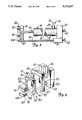
- FIG. 3is a side view, partly in cutaway cross-section, of an inflation apparatus in accordance with the presently preferred embodiment of the present invention.
- FIGS. 4 and 5illustrate the operator mechanism for operating the plunger of the inflation apparatus illustrated in FIG. 3.
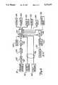
- FIG. 6is a block diagram of the control and display circuit for operating the inflation apparatus according to the present invention and for displaying information concerning the procedure.
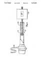
- FIG. 7is an illustration showing the use of the inflation apparatus according to the present invention in a PTCA procedure.
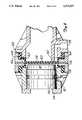
- FIG. 8is a section view of a portion of an inflation apparatus according to the present invention, illustrating an alternative arrangement of the diaphragm.
- FIG. 9is a side view, partly in cutaway cross-section, of an inflation apparatus according to another embodiment of the present invention.
- FIGS. 1 and 2illustrate an inflation apparatus in accordance with one embodiment of the present invention.
- the inflation apparatusincludes a disposable syringe 10 having a barrel 12 containing piston 14 connected to one end of plunger 16.
- Plunger actuator 18is connected to the other end of plunger 16 and is operable to move the plunger, and hence piston 14, axially within barrel 12.
- One end of barrel 12is closed by stainless diaphragm 20. That same end also includes an external lip 22.
- Port 24provides fluid communication between the internal chamber 26 of syringe 10 and the lumen of a balloon catheter (not shown) whose proximal end is connected to connector 28, in fluid communication with port 24.
- Disposable syringe 10is placed within a housing having a frame 30 to which is attached cap 32.
- Detents 34bear against lip 22 of barrel 12 so that forward face 36 of barrel 12 bears against O-ring 38 attached to cap 32.
- Pressure sensor 40is mounted in cap 32 and includes a sensor surface which extends beyond the plane of O-ring 38 to bear tightly against diaphragm 20. Sensor 40 provides an electric signal on leads 42, to be described below.
- Plunger operator 50includes a receiver comprising a first slot 52 sized to receive plunger actuator 18, and a second smaller slot 54 through which plunger 16 extends. Operator 50 is connected to the shaft 56 of motor 58 which in turn is mounted to frame 30. In one form of the invention, motor 58 is mounted to release mechanism 59 which in turn is releasably mounted to frame 30. Release mechanism 59, which may contain compression springs and the like, is arranged to be manually disconnected (such as by a button similar to button 104 described below) from frame 30 to bias motor 58 to the left (in the illustration of FIG. 1), to force plunger 1b to the left (in the illustration of FIG.
- disposable syringe 10is mounted to frame 30 by snapping the distal end of barrel 12 into cap 32 so that detents 34 bear against lip 22 to hold the barrel to the cap.
- diaphragm 20mates snugly against pressure sensor 40 so that pressure in chamber 26 is transferred to sensor 40.
- Actuator 18is received in slot 52 of operator 50.
- syringe 10is axially aligned with motor 58 and its shaft 56. Chamber 26 of syringe 10 may be preloaded with a suitable inflation fluid prior to mounting the syringe into frame 30.
- chamber 26may be automatically loaded with an inflation fluid after the syringe has been mounted to the frame through connection to a fluid supply and operating plunger 16 through microprocessor 120 and motor 58 to draw fluid into the chamber.
- the inflation fluidis a sterile saline and radiopaque mixture.
- the proximal end of a balloon catheter(not shown) is connected through a manifold and tube (not shown in FIG. 1) to connector 28 in fluid communication with chamber 26.
- Motor 58is electrically energized to move operator 50 and plunger 16 to cause piston 14 to move axially in barrel 12 to change the pressure of the fluid in chamber 26.
- the pressure within chamber 26is transmitted through the lumen of the catheter to the dilatation balloon, and is transmitted through diaphragm 20 to pressure sensor 40 to provide a signal output indicative of the pressure within the distal dilatation balloon.
- FIGS. 3-5illustrate a preferred embodiment of the inflation apparatus of the present invention, the preferred embodiment differing from the embodiment shown and described in connection with FIGS. 1 and 2 by the orientation of the motor and the structure of the plunger operator.
- Syringe 10has its forward end connected to frame 70 in the same manner as syringe 10 was connected to frame 30 and cap 32 in FIG. 1.
- Frame 70supports a pressure sensor arranged to bear against a diaphragm on syringe 10, the diaphragm being in fluid communication with chamber 26 of the syringe in the manner described and shown in FIG. 1.
- Connector 28is mounted to the proximal end of tube 72 whose lumen 74 is in fluid communication with chamber 26 as previously described and in fluid communication with the lumen of the balloon catheter (not shown).
- the pressure sensorprovides a signal output via leads 42, as described above.
- Motor 76which receives power through leads 60, is mounted to frame 70 near the forward end of syringe 10.
- Motor shaft 78is connected to plunger operator for axially operating the plunger and changing the pressure of inflation fluid in chamber 26, as heretofore described.
- Plunger operator 80(FIG. 4) includes a first housing 82 having a first slot 84 for receiving plunger actuator 18 (FIG. 3) and a second slot 86 through which plunger 16 extends.
- Second housing 87is fastened to first housing 82 and includes an opening 89 whose width is larger than the width of slot 84.
- a pair of internal slots 88are positioned in the vertical legs of second housing 87 in opening 89 for receiving flanges 90 of a first slide mechanism 92.
- Slide mechanism 92has an opening 93 at least as large as slot 84 to permit passage of plunger actuator 18 therethrough.
- a second slide mechanism 94has a pair of flanges 96 arranged to be received in slots 98 in the opening formed in slide mechanism 92.
- Slide mechanism 94 and portion 100 on slide mechanism 92are arranged to engage the end surface of actuator 18 (FIG. 3) when the actuator is in slot 84.
- housings 82 and 87may be a single member, with slot 84 open through opening 89 to permit passage of plunger actuator 18. Housings 82 and 87 are shown separately in FIG. 4 for clarity. In either case, slide mechanisms 92 and 94 are arranged to slide within opening 89 to open and close opening 89 to permit release of plunger 16 of the syringe.
- Spacers 102connect button 104 to slide mechanism 92.
- Button 104has a pair of flanges 105 that are engaged with engaging slots (not shown) in slot 106 of housing 82 to permit button 104 to reciprocate vertically (in FIG. 4) within slot 106.
- Slide mechanisms 92 and 94are arranged to reciprocate vertically (in FIG. 4) under the influence of button 104 to release plunger actuator 18 from operator 80.
- a scissors mechanism 107(FIG. 5) is pivotally attached to button 104 and to slide mechanism 94 and includes pins 108 engaging slot 110 on housing 82.
- the arrangementis such that upward movement of button 104 (in FIGS. 4 and 5) carries slide mechanism 92 upwardly and pulls slide mechanism 94 downwardly to move the slide mechanisms to clear opening 93 to be free of plunger actuator 18.
- FIG. 6is a block circuit diagram of the apparatus for operating the inflation apparatus, and for displaying and recording pressure information.
- Microprocessor 120receives digital signals representative of pressure from pressure sensor 40 via leads 42, amplifier 122, voltage-controlled oscillator (VCO) 124 and astable multivibrator 126. More particularly, pressure sensor 40 provides an analog signal which is amplified by amplifier 122, the analog signal being converted to an oscillating signal by VCO 124. The oscillating signal operates multivibrator 126 to provide pulses to microprocessor 120, the pulse rate being representative of fluid pressure within chamber 26 of syringe 10.
- VCOvoltage-controlled oscillator
- Microprocessor 120also receives a clock input from clock 128 as well as data from data card 130, electronically programmable read only memory (EPROM) 132 and random access memory (RAM) 134.
- Data card 130may, for example, be a data card unique for each patient on which data is recorded concerning the patient and the patient's history, and onto which microprocessor 120 may record information concerning the PTCA procedure, including the type of catheter used.
- RAM 134contains programs and data for use by the microprocessor during the performance of the procedure, and EPROM 132 contains other data and programs unique to the particular procedure.
- EPROM 132may contain data concerning the profile or diameter of plural dilatation balloons at various pressures.
- Keyboard or wand 136may also be provided for inputting other data to microprocessor 120.
- data concerning the specific dilatation balloon employed in the proceduremay be input through keyboard 136 or by reading encoded stripes on the catheter via a wand.
- Microprocessor 120provides display output on display 138, and/or an alarm output at alarm 140.
- pressure data, time of inflation, numbers of inflations, etc.may all be calculated and processed by microprocessor 120 through the use of pressure data from pressure sensor 40 and time data from clock 128, or prerecorded information from data card 130, EPROM 132 and/or RAM 134.
- Thresholds for inflation parametersmay be preselected or may be calculated using prerecorded algorithms. It is known that dilatation balloons exhibit specific diameters at specific pressures.
- EPROM 132may contain a look-up table or an algorithm to permit microprocessor 120 to calculate balloon diameter correlating to current pressure data for the identified balloon to permit display of information relating to balloon diameter on display 138 for use by the cardiologist.
- Microprocessor 120also receives input from inflation/deflation control 142 and fast vacuum control 144.
- Inflation/deflation control 142may, for example, comprise a rocker switch for inflating the dilatation balloon (in one position) or deflating it (in the opposite position) or it may comprise a slide switch for fast and slow rate of inflation and deflation. A simple rocker or slide switch controls the rate of change pressure.
- control 142may provide a digital signal representative of a desired pressure to direct the microprocessor to operate the motor to inflate or deflate the balloon to a specific pressure, selected by control 142, and measured by the pressure sensor. It is preferred that a fast vacuum control switch 144 also be employed to operate the motor to rapidly deflate the dilatation balloon and apply a vacuum to the syringe.
- Controls 142 and 144are connected by cable 146 to microprocessor 120.
- Microprocessor 120provides an output via digital-to-analog (D/A) converter 148, motor drive circuit 150 to motor 58,76.
- D/Adigital-to-analog
- motor 58,76is operated under the control microprocessor 120. This permits the cardiologist to pre-program an inflation/deflation cycle or series of cycles, including pressure limits and limits on the number of inflations and the duration of inflation, as well as stepped inflation and/or deflation cycles.
- controls 42 and 144may be connected by cable 146 directly to motor drive control 150, so the motor would not operate under the control of microprocessor 120. While direct connection of controls 142 and 144 to the motor drive control provides simpler control, control through the microprocessor permits greater versatility, including pre-programmed inflation/deflation cycles.
- FIG. 7One feature of the present invention is illustrated in FIG. 7 in that the inflation apparatus may be operated with one hand.
- the cardiologistwithout the assistance of a trained aide, may maintain the position of the catheter system 152 (which might comprise an introducer, guide catheter, dilatation catheter and guide wire) with one hand, and operate controls 142 and 144 on housing 154 with the other.
- housing 154may be physically attached to tube 156 extending from connector 28 on syringe 10 to the manifold associated with catheter system 152.
- Microprocessor 120may be mounted within housing 158 and connected via cable 146 (FIG. 6) embedded within tube 152 to housing 154 containing controls 142 and 144.
- housing 154 containing controls 142 and 144may be separate from tube 156 and connected by a separated cable 146 to the microprocessor.
- controls 142 and 144may be connected by a wireless link, such as infrared, ultrasonic, radio or magnetic modulated or pulse rate transmission to a receiver operatively associated with housing 158.
- display 138is mounted in housing 158 for view by the cardiologist.
- Release button 104is also mounted to housing 158 to release the plunger actuator and permit release of pressure from syringe 10 as heretofore described.
- FIG. 7Another optional but desirable release mechanism is also illustrated in FIG. 7 wherein a hand-operated disposable syringe 153 is connected through Y-connector 155 to tube 156.
- Syringe 153has a lock (not shown) to maintain the position of its piston and plunger at a forward end of the barrel when pressure is applied to the chamber of the syringe due to pressure in tube 156.
- the plunger of syringe 153may be moved rearwardly to draw fluid into the syringe and create a vacuum in the balloon.
- Syringe 153may also serve as a supply of inflation fluid to automatically load syringe 10 as described above.
- FIG. 8illustrates a modified form of the diaphragm arrangement wherein syringe barrel 12 includes port 28 and a rubber diaphragm 160 sandwiched between shoulder 162 on barrel 12 and shoulder 164 on cap 166.
- Cap 166is permanently attached to barrel 12, such as by adhesive bonding at annular interface 168.
- Cap 32includes transducer 40 supported by O-ring 170 and retainer 172 in cap 32. Rubber diaphragm 174 is sandwiched between cap body 32 and closure 176, which are bonded together at interface 178.
- FIG. 9illustrates another embodiment of the invention wherein piston 14 of syringe 10 is attached directly to the shaft 180 of motor 182.
- Release mechanism 184is mounted to motor 182 to release shaft 180, release mechanism 184 being manually operable by a button, like button 104.
- release mechanism 184includes bias means, such as a compression spring, to positively move shaft 180 to the right (as depicted in FIG. 9) to draw a vacuum within chamber 26, and hence within the balloon attached to the distal end of catheter 186.
- the embodiment of FIG. 9illustrates two features. First, the emergency release releases the motor shaft rather than the motor (as in the embodiment of FIG. 1) or the plunger (as in the embodiment of FIGS. 3-5).
- piston 14is attached directly to the motor shaft, rather than attaching the plunger to the motor shaft.
- piston 14may be fitted with a receptacle, such as a threaded receiver, to receive the end of motor shaft 180.
- the pistonmay be attached to and detached from the motor shaft for each use. The syringe and piston may be discarded after use.
- the present inventionthus provides an effective power-activated inflation apparatus which is easily and effectively operated with a single hand.
- the apparatusemploys an inexpensive syringe which may be discarded after each procedure, the syringe being the principal portion of the inflation apparatus required to be sterile. Consequently, sterilization problems associated with prior motor-activated inflation devices are eliminated.
- the diaphragm used in the disposable syringe described hereinmay be metal (such as stainless steel) or rubber or plastic. In any case it should exhibit adequate resiliency to transfer fluid pressure in the syringe chamber to the pressure sensor. Additionally, the diaphragm should provide a good fluid seal for the chamber.
- Motor 58, 76may be any suitable motor operated by a signal from motor drive circuit 150.
- the motormay be a stepper motor, linear motor or other motor capable of precision movement.
- the motormay include a gear drive or reduction assembly for added precision or to minimize resistance force on the motor due to pressure on the plunger.
- the motormust be capable of imparting force on piston 14 to produce pressures up to about 300 psi within chamber 26, and hence the dilatation balloon.
- pressure sensor 40is shown mounted to the frame and part of the reusable assembly, the sensor may conveniently be mounted within the disposable syringe (such as to piston 14) and connected through a connector (such as mounted in the plunger operator) to the operating circuit.
- the syringemay be provided with an additional port and fluid connector for manual connection to the pressure sensor at the start of the procedure. While these alternative arrangements for the sensor provide more positive association of the sensor and the pressure within the syringe chamber, they also require that the sensor be disposed or sterilized after each use, thereby adding to the overall cost of the procedure.
Landscapes
- Health & Medical Sciences (AREA)
- Life Sciences & Earth Sciences (AREA)
- Heart & Thoracic Surgery (AREA)
- Engineering & Computer Science (AREA)
- Biophysics (AREA)
- Pulmonology (AREA)
- Child & Adolescent Psychology (AREA)
- Anesthesiology (AREA)
- Biomedical Technology (AREA)
- Hematology (AREA)
- Animal Behavior & Ethology (AREA)
- General Health & Medical Sciences (AREA)
- Public Health (AREA)
- Veterinary Medicine (AREA)
- Media Introduction/Drainage Providing Device (AREA)
Abstract
Description
Claims (23)
Priority Applications (1)
| Application Number | Priority Date | Filing Date | Title |
|---|---|---|---|
| US07/847,826US5273537A (en) | 1992-03-06 | 1992-03-06 | Power-assisted inflation apparatus |
Applications Claiming Priority (1)
| Application Number | Priority Date | Filing Date | Title |
|---|---|---|---|
| US07/847,826US5273537A (en) | 1992-03-06 | 1992-03-06 | Power-assisted inflation apparatus |
Publications (1)
| Publication Number | Publication Date |
|---|---|
| US5273537Atrue US5273537A (en) | 1993-12-28 |
Family
ID=25301602
Family Applications (1)
| Application Number | Title | Priority Date | Filing Date |
|---|---|---|---|
| US07/847,826Expired - LifetimeUS5273537A (en) | 1992-03-06 | 1992-03-06 | Power-assisted inflation apparatus |
Country Status (1)
| Country | Link |
|---|---|
| US (1) | US5273537A (en) |
Cited By (91)
| Publication number | Priority date | Publication date | Assignee | Title |
|---|---|---|---|---|
| US5459700A (en)* | 1993-11-22 | 1995-10-17 | Advanced Cardiovascular Systems, Inc. | Manual timer control for inflation device |
| US5460609A (en)* | 1993-11-22 | 1995-10-24 | Advanced Cardiovascular Systems, Inc. | Electromechanical inflation/deflation system |
| WO1995031245A1 (en)* | 1994-05-17 | 1995-11-23 | Hadasit Medical Research Services & Development Company Ltd. | A system and method for cononary angioplasty |
| EP0702966A3 (en)* | 1994-09-21 | 1996-08-07 | Medrad Inc | Contrast medium delivery systems with patient specific dosage and methods |
| US5545133A (en)* | 1994-09-16 | 1996-08-13 | Scimed Life Systems, Inc. | Balloon catheter with improved pressure source |
| US5562621A (en)* | 1993-11-22 | 1996-10-08 | Advanced Cardiovascular Systems, Inc. | Communication system for linking a medical device with a remote console |
| US5562614A (en)* | 1993-11-22 | 1996-10-08 | Advanced Cardiovascular Systems, Inc. | Programmable manifold system for automatic fluid delivery |
| US5599301A (en)* | 1993-11-22 | 1997-02-04 | Advanced Cardiovascular Systems, Inc. | Motor control system for an automatic catheter inflation system |
| US5647847A (en)* | 1994-09-16 | 1997-07-15 | Scimed Life Systems, Inc. | Balloon catheter with improved pressure source |
| US5695468A (en)* | 1994-09-16 | 1997-12-09 | Scimed Life Systems, Inc. | Balloon catheter with improved pressure source |
| US5739508A (en)* | 1994-07-12 | 1998-04-14 | Medrad, Inc. | Closed loop information path for medical fluid delivery systems |
| US5806519A (en)* | 1993-10-28 | 1998-09-15 | Medrad, Inc. | Total system for contrast delivery |
| US6149627A (en)* | 1993-10-28 | 2000-11-21 | Medrad, Inc. | Multi-patient fluid dispensing |
| US6190354B1 (en) | 1994-09-16 | 2001-02-20 | Scimed Life Systems, Inc. | Balloon catheter with improved pressure source |
| US20040193045A1 (en)* | 2003-02-21 | 2004-09-30 | Nelson Scarborough | Spinal fluid introduction |
| US20040260238A1 (en)* | 2003-05-05 | 2004-12-23 | Call Evan W. | Infusion syringe |
| US20050004518A1 (en)* | 2003-05-05 | 2005-01-06 | Call Evan W. | Infusion syringe |
| US20050209630A1 (en)* | 2004-03-16 | 2005-09-22 | Walter Lutz | Control device for a balloon catheter |
| US20050273056A1 (en)* | 2004-04-08 | 2005-12-08 | Haury John A | Control device for a fluid delivery system |
| US20060095063A1 (en)* | 2004-11-04 | 2006-05-04 | Fujinon Corporation | Balloon controller for endoscopic apparatus |
| EP1654975A1 (en)* | 2004-11-04 | 2006-05-10 | Fujinon Corporation | Balloon controller for endoscope apparatus |
| EP1654979A1 (en)* | 2004-11-05 | 2006-05-10 | Fujinon Corporation | Balloon controller for endoscopic apparatus |
| US20070213662A1 (en)* | 2004-11-24 | 2007-09-13 | Medrad, Inc. | System And Apparatus For Modeling Pressures Generated During An Injection Procedure |
| US7273053B2 (en) | 1997-12-24 | 2007-09-25 | Mario Zocca | Monitoring and control for a laryngeal mask airway device |
| USRE39938E1 (en) | 1996-03-01 | 2007-12-18 | Indian Ocean Medical, Inc. | Gastro-laryngeal mask |
| USD562447S1 (en) | 2004-01-30 | 2008-02-19 | Physician Industries, Inc. | Portion of a syringe |
| US7331346B2 (en) | 1997-12-24 | 2008-02-19 | Indian Ocean Medical, Inc. | Monitoring and control for a laryngeal mask airway device |
| USD579561S1 (en) | 2004-01-30 | 2008-10-28 | Physician Industries, Inc. | Portion of a syringe |
| EP2014330A2 (en) | 2007-07-09 | 2009-01-14 | Mego Afek Ac. Ltd. | Inflation/deflation system for a catheter |
| US7493901B2 (en) | 1998-10-06 | 2009-02-24 | The Laryngeal Mask Company Ltd. | Laryngeal mask airway device |
| AU2001269309B2 (en)* | 2000-07-07 | 2009-09-24 | Indian Ocean Medical Inc. | Monitoring and control for a laryngeal mask airway device |
| US7641668B2 (en) | 2003-05-16 | 2010-01-05 | Scimed Life Systems, Inc. | Fluid delivery system and related methods of use |
| US20100114040A1 (en)* | 2008-11-05 | 2010-05-06 | Medrad, Inc. | Fluid mixing control device for a multi-fluid delivery system |
| US20110082450A1 (en)* | 2009-10-02 | 2011-04-07 | Cardiofocus, Inc. | Cardiac ablation system with inflatable member having multiple inflation settings |
| WO2012051474A1 (en)* | 2010-10-15 | 2012-04-19 | Phoenix Biomedical, Inc. | Controlled inflation of an expandable member during a medical procedure |
| US8192397B2 (en) | 2005-06-21 | 2012-06-05 | Medrad, Inc. | Medical fluid injection and inflation system |
| US8398654B2 (en) | 2008-04-17 | 2013-03-19 | Allergan, Inc. | Implantable access port device and attachment system |
| US8409221B2 (en) | 2008-04-17 | 2013-04-02 | Allergan, Inc. | Implantable access port device having a safety cap |
| US8506532B2 (en) | 2009-08-26 | 2013-08-13 | Allergan, Inc. | System including access port and applicator tool |
| US8585594B2 (en) | 2006-05-24 | 2013-11-19 | Phoenix Biomedical, Inc. | Methods of assessing inner surfaces of body lumens or organs |
| US8708979B2 (en) | 2009-08-26 | 2014-04-29 | Apollo Endosurgery, Inc. | Implantable coupling device |
| US8715158B2 (en) | 2009-08-26 | 2014-05-06 | Apollo Endosurgery, Inc. | Implantable bottom exit port |
| US8747358B2 (en) | 2000-10-18 | 2014-06-10 | Bayer Medical Care Inc. | Injector system with a manual control device |
| US8783256B2 (en) | 2005-05-27 | 2014-07-22 | The Laryngeal Mask Company Ltd. | Laryngeal mask airway device |
| US8801597B2 (en) | 2011-08-25 | 2014-08-12 | Apollo Endosurgery, Inc. | Implantable access port with mesh attachment rivets |
| US8821373B2 (en) | 2011-05-10 | 2014-09-02 | Apollo Endosurgery, Inc. | Directionless (orientation independent) needle injection port |
| US8858421B2 (en) | 2011-11-15 | 2014-10-14 | Apollo Endosurgery, Inc. | Interior needle stick guard stems for tubes |
| US8882655B2 (en) | 2010-09-14 | 2014-11-11 | Apollo Endosurgery, Inc. | Implantable access port system |
| US8882728B2 (en) | 2010-02-10 | 2014-11-11 | Apollo Endosurgery, Inc. | Implantable injection port |
| US8905916B2 (en) | 2010-08-16 | 2014-12-09 | Apollo Endosurgery, Inc. | Implantable access port system |
| US8986247B2 (en) | 2011-06-29 | 2015-03-24 | Stuart H. Miller | Insufflation pump |
| US8992415B2 (en) | 2010-04-30 | 2015-03-31 | Apollo Endosurgery, Inc. | Implantable device to protect tubing from puncture |
| US9008759B2 (en) | 2007-07-17 | 2015-04-14 | Bayer Medical Care Inc. | Devices and systems for determination of parameters for a procedure, for estimation of cardiopulmonary function and for fluid delivery |
| US9089395B2 (en) | 2011-11-16 | 2015-07-28 | Appolo Endosurgery, Inc. | Pre-loaded septum for use with an access port |
| US9125718B2 (en) | 2010-04-30 | 2015-09-08 | Apollo Endosurgery, Inc. | Electronically enhanced access port for a fluid filled implant |
| US9192501B2 (en) | 2010-04-30 | 2015-11-24 | Apollo Endosurgery, Inc. | Remotely powered remotely adjustable gastric band system |
| US9199069B2 (en) | 2011-10-20 | 2015-12-01 | Apollo Endosurgery, Inc. | Implantable injection port |
| US9265904B2 (en) | 2009-07-06 | 2016-02-23 | Teleflex Life Sciences | Artificial airway |
| US20160058985A1 (en)* | 2014-08-29 | 2016-03-03 | Acclarent, Inc. | Automated inflator for balloon dilator |
| US9302044B2 (en) | 2006-12-29 | 2016-04-05 | Bayer Healthcare Llc | Patient-based parameter generation systems for medical injection procedures |
| US9307893B2 (en) | 2011-12-29 | 2016-04-12 | Cook Medical Technologies Llc | Space-optimized visualization catheter with camera train holder in a catheter with off-centered lumens |
| US9421330B2 (en) | 2008-11-03 | 2016-08-23 | Bayer Healthcare Llc | Mitigation of contrast-induced nephropathy |
| US9433730B2 (en) | 2013-03-14 | 2016-09-06 | Bayer Healthcare Llc | Fluid mixing control device for a multi-fluid delivery system |
| US9528897B2 (en) | 2009-08-13 | 2016-12-27 | Chimden Medical Pty Ltd | Pressure indicator |
| US9616166B2 (en) | 2004-11-16 | 2017-04-11 | Bayer Healthcare Llc | Systems and methods of determining injection protocols for diagnostic imaging procedures |
| EP3043859A4 (en)* | 2013-09-12 | 2017-05-10 | Hansa Medical Products, INC. | Tissue modification methods and apparatus |
| US9668643B2 (en) | 2011-12-29 | 2017-06-06 | Cook Medical Technologies Llc | Space-optimized visualization catheter with oblong shape |
| US9675772B2 (en) | 2010-10-15 | 2017-06-13 | The Laryngeal Mask Company Limited | Artificial airway device |
| US9700672B2 (en) | 2011-09-21 | 2017-07-11 | Bayer Healthcare Llc | Continuous multi-fluid pump device, drive and actuating system and method |
| US9943651B2 (en) | 2011-10-11 | 2018-04-17 | Hospitech Respiration Ltd. | Pressure regulating syringe and method therefor |
| US9949704B2 (en) | 2012-05-14 | 2018-04-24 | Bayer Healthcare Llc | Systems and methods for determination of pharmaceutical fluid injection protocols based on x-ray tube voltage |
| US9959389B2 (en) | 2010-06-24 | 2018-05-01 | Bayer Healthcare Llc | Modeling of pharmaceutical propagation and parameter generation for injection protocols |
| US9974912B2 (en) | 2010-10-01 | 2018-05-22 | Teleflex Life Sciences Unlimited Company | Artificial airway device |
| US10118024B2 (en) | 2015-02-19 | 2018-11-06 | Stuart H. Miller | Insufflation pump |
| US10244927B2 (en) | 2011-12-29 | 2019-04-02 | Cook Medical Technologies Llc | Space-optimized visualization catheter with camera train holder |
| US10507319B2 (en) | 2015-01-09 | 2019-12-17 | Bayer Healthcare Llc | Multiple fluid delivery system with multi-use disposable set and features thereof |
| US10549054B2 (en) | 2011-02-02 | 2020-02-04 | Teleflex Life Sciences Unlimited Company | Artificial airway |
| US10576229B2 (en) | 2009-03-03 | 2020-03-03 | The Laryngeal Mask Company Limited | Artificial airway device |
| US10806327B2 (en) | 2011-11-30 | 2020-10-20 | Teleflex Life Sciences Pte, Ltd. | Laryngeal mask for use with an endoscope |
| US10898638B2 (en) | 2016-03-03 | 2021-01-26 | Bayer Healthcare Llc | System and method for improved fluid delivery in multi-fluid injector systems |
| US20210205578A1 (en)* | 2020-01-03 | 2021-07-08 | Stanley Batiste | Catheter clearance device and method of use |
| US11141535B2 (en) | 2017-08-31 | 2021-10-12 | Bayer Healthcare Llc | Fluid path impedance assessment for improving fluid delivery performance |
| US11278853B2 (en) | 2013-03-13 | 2022-03-22 | Bayer Healthcare Llc | Method for controlling fluid accuracy and backflow compensation |
| US11478581B2 (en) | 2017-08-31 | 2022-10-25 | Bayer Healthcare Llc | Fluid injector system volume compensation system and method |
| US11598664B2 (en) | 2017-08-31 | 2023-03-07 | Bayer Healthcare Llc | Injector pressure calibration system and method |
| US11779702B2 (en) | 2017-08-31 | 2023-10-10 | Bayer Healthcare Llc | Method for dynamic pressure control in a fluid injector system |
| US11786652B2 (en) | 2017-08-31 | 2023-10-17 | Bayer Healthcare Llc | System and method for drive member position and fluid injector system mechanical calibration |
| US12208239B2 (en) | 2018-08-28 | 2025-01-28 | Bayer Healthcare Llc | Fluid injector system, method of preventing fluid backflow, and computer program product |
| US12251544B2 (en) | 2018-04-19 | 2025-03-18 | Bayer Healthcare Llc | System and method for air detection in fluid injector |
| US12263326B2 (en) | 2016-11-14 | 2025-04-01 | Bayer Healthcare Llc | Methods and systems for verifying the contents of a syringe used for medical fluid delivery |
| US12427249B2 (en) | 2018-08-28 | 2025-09-30 | Bayer Healthcare Llc | Fluid injector system with improved ratio performance |
Citations (51)
| Publication number | Priority date | Publication date | Assignee | Title |
|---|---|---|---|---|
| US3155090A (en)* | 1962-01-10 | 1964-11-03 | Holter Company | Hypodermic syringe operating means |
| US3425416A (en)* | 1966-05-23 | 1969-02-04 | Horton Hampton Loughry | Hypodermic injection syringe controlled by pressure of discharge |
| DE1909540A1 (en)* | 1969-02-26 | 1970-09-17 | Dibbern Dr Rer Nat Hans Werner | Microdosing device |
| US3631847A (en)* | 1966-03-04 | 1972-01-04 | James C Hobbs | Method and apparatus for injecting fluid into the vascular system |
| US3701345A (en)* | 1970-09-29 | 1972-10-31 | Medrad Inc | Angiographic injector equipment |
| US3720199A (en)* | 1971-05-14 | 1973-03-13 | Avco Corp | Safety connector for balloon pump |
| US3858581A (en)* | 1973-07-02 | 1975-01-07 | Dean Kamen | Medication injection device |
| US3945379A (en)* | 1974-08-08 | 1976-03-23 | Smithkline Corporation | Injection device |
| US4036232A (en)* | 1976-04-19 | 1977-07-19 | Abbott Laboratories | Aspiration device |
| US4180067A (en)* | 1976-09-28 | 1979-12-25 | Pye (Electronic Products) Limited | Apparatus for delivering fluids with controlled rates of flow |
| US4191187A (en)* | 1977-03-09 | 1980-03-04 | National Research Development Corporation | Medical apparatus |
| US4269185A (en)* | 1979-01-08 | 1981-05-26 | Whitney Douglass G | Self contained mechanical injector |
| US4285340A (en)* | 1979-03-16 | 1981-08-25 | Gezari Walter A | Apparatus for controlling the pressure in a tracheal cuff |
| US4331156A (en)* | 1980-03-28 | 1982-05-25 | University Patents, Inc. | Esophageal cardiac pulse monitoring apparatus and method |
| US4332254A (en)* | 1980-11-17 | 1982-06-01 | Advanced Catheter Systems, Inc. | System for filling and inflating and deflating a vascular dilating cathether assembly |
| US4407659A (en)* | 1980-06-06 | 1983-10-04 | Varian Associates, Inc. | Drive system |
| US4409986A (en)* | 1980-03-28 | 1983-10-18 | University Patents, Inc. | Esophageal cardiac pulse monitoring apparatus and method |
| US4435173A (en)* | 1982-03-05 | 1984-03-06 | Delta Medical Industries | Variable rate syringe pump for insulin delivery |
| US4439185A (en)* | 1981-10-21 | 1984-03-27 | Advanced Cardiovascular Systems, Inc. | Inflating and deflating device for vascular dilating catheter assembly |
| US4439186A (en)* | 1981-09-29 | 1984-03-27 | Adolf Kuhl | Dilation device |
| US4508532A (en)* | 1983-09-09 | 1985-04-02 | Ninetronix, Inc. | Ophthalmic aspirator/irrigator and cystotome |
| US4525156A (en)* | 1983-02-16 | 1985-06-25 | Benusa John E | Method for stomach lavage |
| US4529401A (en)* | 1982-01-11 | 1985-07-16 | Cardiac Pacemakers, Inc. | Ambulatory infusion pump having programmable parameters |
| US4529397A (en)* | 1982-02-09 | 1985-07-16 | Sartorius Gmbh | Cardioplegic controlling and regulating system |
| US4560979A (en)* | 1983-04-22 | 1985-12-24 | Intermedicat Gmbh | Method for triggering an alarm in an infusion syringe |
| US4573992A (en)* | 1982-05-17 | 1986-03-04 | Solco Basel Ag | Apparatus for receiving and reinfusing blood |
| US4585439A (en)* | 1983-09-07 | 1986-04-29 | Disetronic Ag. | Portable infusion unit |
| US4613327A (en)* | 1984-01-26 | 1986-09-23 | Tegrarian Haig V | Apparatus for infusing blood and other related fluids into a patient's body |
| US4627835A (en)* | 1985-03-11 | 1986-12-09 | Strato Medical Corporation | Tubing assembly for infusion device |
| US4666430A (en)* | 1984-12-05 | 1987-05-19 | I-Flow Corporation | Infusion pump |
| US4668220A (en)* | 1984-10-26 | 1987-05-26 | Infors Gmbh | Infusion pump |
| US4697574A (en)* | 1985-02-20 | 1987-10-06 | Medicorp Research Laboratories Corp. | Pump for assistance in circulation |
| US4731058A (en)* | 1986-05-22 | 1988-03-15 | Pharmacia Deltec, Inc. | Drug delivery system |
| US4767406A (en)* | 1985-10-11 | 1988-08-30 | Vickers Plc. | Syringe pumps |
| US4804368A (en)* | 1986-12-05 | 1989-02-14 | C. R. Bard, Inc. | Battery operated miniature syringe infusion pump and improved halfnut therefor |
| US4887608A (en)* | 1986-01-31 | 1989-12-19 | Boston Scientific Corporation | Method and apparatus for estimating tissue damage |
| US4909783A (en)* | 1986-07-16 | 1990-03-20 | Morrison David P | Intra-ocular pressure apparatus |
| US4934996A (en)* | 1984-02-27 | 1990-06-19 | Boston Scientific Corporation | Pressure-controlled intermittent coronary sinus occlusion apparatus and method |
| US4944726A (en)* | 1988-11-03 | 1990-07-31 | Applied Vascular Devices | Device for power injection of fluids |
| US4969470A (en)* | 1984-02-27 | 1990-11-13 | Boston Scientific Corporation | Heart analysis using pressure-controlled intermittent coronary sinus occlusion |
| US4978335A (en)* | 1989-09-29 | 1990-12-18 | Medex, Inc. | Infusion pump with bar code input to computer |
| US5004472A (en)* | 1988-08-10 | 1991-04-02 | Wallace William D | Medical pressure sensing and display system |
| US5006112A (en)* | 1988-11-12 | 1991-04-09 | Mts Schweinfurt Gmbh | Syringe pump |
| US5015223A (en)* | 1989-12-06 | 1991-05-14 | Zip-Pak, Incorporated | Hotseal jaws and cutoff knife assembly for processing thermoplastic film bag making material |
| US5019037A (en)* | 1989-07-06 | 1991-05-28 | Alcon Laboratories, Inc. | Pneumatic retinopexy injector |
| US5034003A (en)* | 1988-11-21 | 1991-07-23 | Raymond Denance | Injection device having a stabilizing sight which actuates a safety valve for the needle |
| US5047012A (en)* | 1989-02-01 | 1991-09-10 | Richard Wolf, Gmbh | Motorized syringe with multiple port manifold |
| US5090963A (en)* | 1990-10-19 | 1992-02-25 | Product Development (Z.G.S.) Ltd. | Electrochemically driven metering medicament dispenser |
| US5135488A (en)* | 1989-03-17 | 1992-08-04 | Merit Medical Systems, Inc. | System and method for monitoring, displaying and recording balloon catheter inflation data |
| US5152776A (en)* | 1990-04-03 | 1992-10-06 | Cordis Corporation | Balloon inflation device |
| US5171299A (en)* | 1991-08-02 | 1992-12-15 | Baxter International Inc. | Balloon catheter inflation pressure and diameter display apparatus and method |
- 1992
- 1992-03-06USUS07/847,826patent/US5273537A/ennot_activeExpired - Lifetime
Patent Citations (55)
| Publication number | Priority date | Publication date | Assignee | Title |
|---|---|---|---|---|
| US3155090A (en)* | 1962-01-10 | 1964-11-03 | Holter Company | Hypodermic syringe operating means |
| US3631847A (en)* | 1966-03-04 | 1972-01-04 | James C Hobbs | Method and apparatus for injecting fluid into the vascular system |
| US3425416A (en)* | 1966-05-23 | 1969-02-04 | Horton Hampton Loughry | Hypodermic injection syringe controlled by pressure of discharge |
| DE1909540A1 (en)* | 1969-02-26 | 1970-09-17 | Dibbern Dr Rer Nat Hans Werner | Microdosing device |
| US3701345A (en)* | 1970-09-29 | 1972-10-31 | Medrad Inc | Angiographic injector equipment |
| US3720199A (en)* | 1971-05-14 | 1973-03-13 | Avco Corp | Safety connector for balloon pump |
| US3858581A (en)* | 1973-07-02 | 1975-01-07 | Dean Kamen | Medication injection device |
| US3945379A (en)* | 1974-08-08 | 1976-03-23 | Smithkline Corporation | Injection device |
| US4036232A (en)* | 1976-04-19 | 1977-07-19 | Abbott Laboratories | Aspiration device |
| US4180067A (en)* | 1976-09-28 | 1979-12-25 | Pye (Electronic Products) Limited | Apparatus for delivering fluids with controlled rates of flow |
| US4191187A (en)* | 1977-03-09 | 1980-03-04 | National Research Development Corporation | Medical apparatus |
| US4269185A (en)* | 1979-01-08 | 1981-05-26 | Whitney Douglass G | Self contained mechanical injector |
| US4285340A (en)* | 1979-03-16 | 1981-08-25 | Gezari Walter A | Apparatus for controlling the pressure in a tracheal cuff |
| US4331156A (en)* | 1980-03-28 | 1982-05-25 | University Patents, Inc. | Esophageal cardiac pulse monitoring apparatus and method |
| US4409986A (en)* | 1980-03-28 | 1983-10-18 | University Patents, Inc. | Esophageal cardiac pulse monitoring apparatus and method |
| US4407659A (en)* | 1980-06-06 | 1983-10-04 | Varian Associates, Inc. | Drive system |
| US4332254A (en)* | 1980-11-17 | 1982-06-01 | Advanced Catheter Systems, Inc. | System for filling and inflating and deflating a vascular dilating cathether assembly |
| US4439186A (en)* | 1981-09-29 | 1984-03-27 | Adolf Kuhl | Dilation device |
| US4439185A (en)* | 1981-10-21 | 1984-03-27 | Advanced Cardiovascular Systems, Inc. | Inflating and deflating device for vascular dilating catheter assembly |
| US4529401A (en)* | 1982-01-11 | 1985-07-16 | Cardiac Pacemakers, Inc. | Ambulatory infusion pump having programmable parameters |
| US4529397A (en)* | 1982-02-09 | 1985-07-16 | Sartorius Gmbh | Cardioplegic controlling and regulating system |
| US4435173A (en)* | 1982-03-05 | 1984-03-06 | Delta Medical Industries | Variable rate syringe pump for insulin delivery |
| US4573992A (en)* | 1982-05-17 | 1986-03-04 | Solco Basel Ag | Apparatus for receiving and reinfusing blood |
| US4525156A (en)* | 1983-02-16 | 1985-06-25 | Benusa John E | Method for stomach lavage |
| US4560979A (en)* | 1983-04-22 | 1985-12-24 | Intermedicat Gmbh | Method for triggering an alarm in an infusion syringe |
| US4585439A (en)* | 1983-09-07 | 1986-04-29 | Disetronic Ag. | Portable infusion unit |
| US4508532A (en)* | 1983-09-09 | 1985-04-02 | Ninetronix, Inc. | Ophthalmic aspirator/irrigator and cystotome |
| US4613327A (en)* | 1984-01-26 | 1986-09-23 | Tegrarian Haig V | Apparatus for infusing blood and other related fluids into a patient's body |
| US4934996A (en)* | 1984-02-27 | 1990-06-19 | Boston Scientific Corporation | Pressure-controlled intermittent coronary sinus occlusion apparatus and method |
| US4969470A (en)* | 1984-02-27 | 1990-11-13 | Boston Scientific Corporation | Heart analysis using pressure-controlled intermittent coronary sinus occlusion |
| US4668220A (en)* | 1984-10-26 | 1987-05-26 | Infors Gmbh | Infusion pump |
| US4666430A (en)* | 1984-12-05 | 1987-05-19 | I-Flow Corporation | Infusion pump |
| US4697574A (en)* | 1985-02-20 | 1987-10-06 | Medicorp Research Laboratories Corp. | Pump for assistance in circulation |
| US4627835A (en)* | 1985-03-11 | 1986-12-09 | Strato Medical Corporation | Tubing assembly for infusion device |
| US4767406A (en)* | 1985-10-11 | 1988-08-30 | Vickers Plc. | Syringe pumps |
| US4887608A (en)* | 1986-01-31 | 1989-12-19 | Boston Scientific Corporation | Method and apparatus for estimating tissue damage |
| US4731058A (en)* | 1986-05-22 | 1988-03-15 | Pharmacia Deltec, Inc. | Drug delivery system |
| US4909783A (en)* | 1986-07-16 | 1990-03-20 | Morrison David P | Intra-ocular pressure apparatus |
| US4804368A (en)* | 1986-12-05 | 1989-02-14 | C. R. Bard, Inc. | Battery operated miniature syringe infusion pump and improved halfnut therefor |
| US5021046A (en)* | 1988-08-10 | 1991-06-04 | Utah Medical Products, Inc. | Medical pressure sensing and display system |
| US5004472B1 (en)* | 1988-08-10 | 1995-02-28 | Utah Medical Products Inc | Medical pressure sensing and display system |
| US5004472A (en)* | 1988-08-10 | 1991-04-02 | Wallace William D | Medical pressure sensing and display system |
| US5009662A (en)* | 1988-08-10 | 1991-04-23 | Wallace William D | Medical pressure sensing and display system |
| US5009662B1 (en)* | 1988-08-10 | 1995-02-14 | Utah Medical Products | Medical pressure sensing and display system |
| US4944726A (en)* | 1988-11-03 | 1990-07-31 | Applied Vascular Devices | Device for power injection of fluids |
| US5006112A (en)* | 1988-11-12 | 1991-04-09 | Mts Schweinfurt Gmbh | Syringe pump |
| US5034003A (en)* | 1988-11-21 | 1991-07-23 | Raymond Denance | Injection device having a stabilizing sight which actuates a safety valve for the needle |
| US5047012A (en)* | 1989-02-01 | 1991-09-10 | Richard Wolf, Gmbh | Motorized syringe with multiple port manifold |
| US5135488A (en)* | 1989-03-17 | 1992-08-04 | Merit Medical Systems, Inc. | System and method for monitoring, displaying and recording balloon catheter inflation data |
| US5019037A (en)* | 1989-07-06 | 1991-05-28 | Alcon Laboratories, Inc. | Pneumatic retinopexy injector |
| US4978335A (en)* | 1989-09-29 | 1990-12-18 | Medex, Inc. | Infusion pump with bar code input to computer |
| US5015223A (en)* | 1989-12-06 | 1991-05-14 | Zip-Pak, Incorporated | Hotseal jaws and cutoff knife assembly for processing thermoplastic film bag making material |
| US5152776A (en)* | 1990-04-03 | 1992-10-06 | Cordis Corporation | Balloon inflation device |
| US5090963A (en)* | 1990-10-19 | 1992-02-25 | Product Development (Z.G.S.) Ltd. | Electrochemically driven metering medicament dispenser |
| US5171299A (en)* | 1991-08-02 | 1992-12-15 | Baxter International Inc. | Balloon catheter inflation pressure and diameter display apparatus and method |
Cited By (151)
| Publication number | Priority date | Publication date | Assignee | Title |
|---|---|---|---|---|
| US6901283B2 (en) | 1993-10-28 | 2005-05-31 | Medrad, Inc. | Adjusting a condition of a fluid medium to produce an image of a patient |
| US6306117B1 (en) | 1993-10-28 | 2001-10-23 | Medrad, Inc. | Multi-patient fluid dispensing |
| US6149627A (en)* | 1993-10-28 | 2000-11-21 | Medrad, Inc. | Multi-patient fluid dispensing |
| US5806519A (en)* | 1993-10-28 | 1998-09-15 | Medrad, Inc. | Total system for contrast delivery |
| US7427281B2 (en) | 1993-10-28 | 2008-09-23 | Medrad, Inc. | Method of delivering fluid mixtures to multiple patients |
| US6731971B2 (en) | 1993-10-28 | 2004-05-04 | Medrad, Inc. | Fluid delivery system including a reusable flow path and a per-patient disposable fluid path |
| US6442418B1 (en) | 1993-10-28 | 2002-08-27 | Medrad, Inc. | Total system for contrast delivery |
| US5599301A (en)* | 1993-11-22 | 1997-02-04 | Advanced Cardiovascular Systems, Inc. | Motor control system for an automatic catheter inflation system |
| US5562614A (en)* | 1993-11-22 | 1996-10-08 | Advanced Cardiovascular Systems, Inc. | Programmable manifold system for automatic fluid delivery |
| US5562621A (en)* | 1993-11-22 | 1996-10-08 | Advanced Cardiovascular Systems, Inc. | Communication system for linking a medical device with a remote console |
| US5460609A (en)* | 1993-11-22 | 1995-10-24 | Advanced Cardiovascular Systems, Inc. | Electromechanical inflation/deflation system |
| US5459700A (en)* | 1993-11-22 | 1995-10-17 | Advanced Cardiovascular Systems, Inc. | Manual timer control for inflation device |
| WO1995031245A1 (en)* | 1994-05-17 | 1995-11-23 | Hadasit Medical Research Services & Development Company Ltd. | A system and method for cononary angioplasty |
| US5891089A (en)* | 1994-05-17 | 1999-04-06 | Hadasit Medical Research Services & Development | System and method for coronary angioplasty |
| US5739508A (en)* | 1994-07-12 | 1998-04-14 | Medrad, Inc. | Closed loop information path for medical fluid delivery systems |
| US5920054A (en)* | 1994-07-12 | 1999-07-06 | Medrad, Inc. | Closed loop information path for medical fluid delivery systems |
| US5728064A (en)* | 1994-09-16 | 1998-03-17 | Scimed Life Systems, Inc. | Balloon catheter with improved pressure source |
| US6190354B1 (en) | 1994-09-16 | 2001-02-20 | Scimed Life Systems, Inc. | Balloon catheter with improved pressure source |
| US5695468A (en)* | 1994-09-16 | 1997-12-09 | Scimed Life Systems, Inc. | Balloon catheter with improved pressure source |
| US5647847A (en)* | 1994-09-16 | 1997-07-15 | Scimed Life Systems, Inc. | Balloon catheter with improved pressure source |
| US5545133A (en)* | 1994-09-16 | 1996-08-13 | Scimed Life Systems, Inc. | Balloon catheter with improved pressure source |
| US6385483B1 (en) | 1994-09-21 | 2002-05-07 | Medrad, Inc. | Patient specific dosing contrast delivery systems and methods |
| US5840026A (en)* | 1994-09-21 | 1998-11-24 | Medrad, Inc. | Patient specific dosing contrast delivery systems and methods |
| EP0702966A3 (en)* | 1994-09-21 | 1996-08-07 | Medrad Inc | Contrast medium delivery systems with patient specific dosage and methods |
| EP1262206A3 (en)* | 1994-09-21 | 2003-03-19 | Medrad, Inc. | Patient specific dosing contrast media delivery systems |
| US7313431B2 (en) | 1994-09-21 | 2007-12-25 | Medrad, Inc. | System and method for inflating a balloon catheter and delivering fluid media to a patient |
| US6889074B2 (en) | 1994-09-21 | 2005-05-03 | Medrad, Inc. | Patient specific dosing contrast delivery systems and methods |
| USRE39938E1 (en) | 1996-03-01 | 2007-12-18 | Indian Ocean Medical, Inc. | Gastro-laryngeal mask |
| US7331346B2 (en) | 1997-12-24 | 2008-02-19 | Indian Ocean Medical, Inc. | Monitoring and control for a laryngeal mask airway device |
| US7273053B2 (en) | 1997-12-24 | 2007-09-25 | Mario Zocca | Monitoring and control for a laryngeal mask airway device |
| US7506648B2 (en) | 1998-10-06 | 2009-03-24 | The Laryngeal Mask Company Ltd. | Laryngeal mask airway device |
| US7493901B2 (en) | 1998-10-06 | 2009-02-24 | The Laryngeal Mask Company Ltd. | Laryngeal mask airway device |
| AU2001269309B2 (en)* | 2000-07-07 | 2009-09-24 | Indian Ocean Medical Inc. | Monitoring and control for a laryngeal mask airway device |
| US8747358B2 (en) | 2000-10-18 | 2014-06-10 | Bayer Medical Care Inc. | Injector system with a manual control device |
| US9764081B2 (en) | 2000-10-18 | 2017-09-19 | Bayer Healthcare Llc | Fluid path containing a pressure isolation valve |
| US9833559B2 (en) | 2000-10-18 | 2017-12-05 | Bayer Healthcare Llc | Pressure isolation mechanisms, method of use thereof and fluid delivery systems including pressure isolation mechanisms |
| US20100094229A1 (en)* | 2003-02-21 | 2010-04-15 | Smith & Nephew, Inc. | Spinal fluid introduction |
| US7662133B2 (en) | 2003-02-21 | 2010-02-16 | Smith & Nephew, Inc. | Spinal fluid introduction |
| US20040193045A1 (en)* | 2003-02-21 | 2004-09-30 | Nelson Scarborough | Spinal fluid introduction |
| US7291131B2 (en) | 2003-05-05 | 2007-11-06 | Physicians Industries, Inc. | Infusion syringe |
| US7351223B2 (en) | 2003-05-05 | 2008-04-01 | Physicians Industries, Inc. | Infusion syringe with integrated pressure transducer |
| US20050004518A1 (en)* | 2003-05-05 | 2005-01-06 | Call Evan W. | Infusion syringe |
| US20040260238A1 (en)* | 2003-05-05 | 2004-12-23 | Call Evan W. | Infusion syringe |
| US7641668B2 (en) | 2003-05-16 | 2010-01-05 | Scimed Life Systems, Inc. | Fluid delivery system and related methods of use |
| US8628555B2 (en) | 2003-05-16 | 2014-01-14 | Boston Scientific Scimed, Inc. | Fluid delivery system and related methods of use |
| US8147511B2 (en) | 2003-05-16 | 2012-04-03 | Boston Scientific Scimed, Inc. | Fluid delivery system and related methods of use |
| USD562447S1 (en) | 2004-01-30 | 2008-02-19 | Physician Industries, Inc. | Portion of a syringe |
| USD579561S1 (en) | 2004-01-30 | 2008-10-28 | Physician Industries, Inc. | Portion of a syringe |
| US20050209630A1 (en)* | 2004-03-16 | 2005-09-22 | Walter Lutz | Control device for a balloon catheter |
| EP1576981A3 (en)* | 2004-03-16 | 2005-12-07 | WL-tec GmbH | Controller for a balloon catheter |
| US7879008B2 (en) | 2004-04-08 | 2011-02-01 | Medrad, Inc. | Control device for a fluid delivery system |
| US20050273056A1 (en)* | 2004-04-08 | 2005-12-08 | Haury John A | Control device for a fluid delivery system |
| US20060116549A1 (en)* | 2004-11-04 | 2006-06-01 | Fujinon Corporation | Balloon controller for endoscope apparatus |
| US20060095063A1 (en)* | 2004-11-04 | 2006-05-04 | Fujinon Corporation | Balloon controller for endoscopic apparatus |
| EP1654975A1 (en)* | 2004-11-04 | 2006-05-10 | Fujinon Corporation | Balloon controller for endoscope apparatus |
| US7713191B2 (en) | 2004-11-04 | 2010-05-11 | Fujinon Corporation | Balloon controller for endoscope apparatus |
| US8439825B2 (en)* | 2004-11-04 | 2013-05-14 | Fujifilm Corporation | Balloon controller for endoscopic apparatus |
| EP1654979A1 (en)* | 2004-11-05 | 2006-05-10 | Fujinon Corporation | Balloon controller for endoscopic apparatus |
| US20060116586A1 (en)* | 2004-11-05 | 2006-06-01 | Fujinon Corporation | Balloon controller for endoscopic apparatus |
| US7901347B2 (en) | 2004-11-05 | 2011-03-08 | Fujinon Corporation | Balloon controller for endoscopic apparatus |
| US9616166B2 (en) | 2004-11-16 | 2017-04-11 | Bayer Healthcare Llc | Systems and methods of determining injection protocols for diagnostic imaging procedures |
| US9950107B2 (en) | 2004-11-24 | 2018-04-24 | Bayer Healthcare Llc | Systems and methods for managing workflow for injection procedures |
| US10166326B2 (en) | 2004-11-24 | 2019-01-01 | Bayer Healthcare Llc | Devices, systems and methods for determining parameters of one or more phases of an injection procedure |
| US20070213662A1 (en)* | 2004-11-24 | 2007-09-13 | Medrad, Inc. | System And Apparatus For Modeling Pressures Generated During An Injection Procedure |
| US7925330B2 (en) | 2004-11-24 | 2011-04-12 | Medrad, Inc. | Devices, systems and methods for determining parameters of one or more phases of an injection procedure |
| US9238099B2 (en) | 2004-11-24 | 2016-01-19 | Bayer Healthcare Llc | System and apparatus for modeling pressures generated during an injection procedure |
| US20070282263A1 (en)* | 2004-11-24 | 2007-12-06 | Medrad, Inc. | Devices, systems and methods for determining parameters of one or more phases of an injection procedure |
| US9498591B2 (en) | 2005-05-27 | 2016-11-22 | The Laryngeal Mask Company Ltd. | Laryngeal mask airway device with a support for preventing occlusion |
| US9522245B2 (en) | 2005-05-27 | 2016-12-20 | The Laryngeal Mask Company Ltd. | Laryngeal mask airway device and method of manufacture |
| US9662465B2 (en) | 2005-05-27 | 2017-05-30 | The Laryngeal Mask Company Ltd. | Laryngeal mask airway device |
| US8783256B2 (en) | 2005-05-27 | 2014-07-22 | The Laryngeal Mask Company Ltd. | Laryngeal mask airway device |
| US8192397B2 (en) | 2005-06-21 | 2012-06-05 | Medrad, Inc. | Medical fluid injection and inflation system |
| US8585594B2 (en) | 2006-05-24 | 2013-11-19 | Phoenix Biomedical, Inc. | Methods of assessing inner surfaces of body lumens or organs |
| US9302044B2 (en) | 2006-12-29 | 2016-04-05 | Bayer Healthcare Llc | Patient-based parameter generation systems for medical injection procedures |
| US10463782B2 (en) | 2006-12-29 | 2019-11-05 | Bayer Healthcare Llc | Patient-based parameter generation systems for medical injection procedures |
| EP2014330A2 (en) | 2007-07-09 | 2009-01-14 | Mego Afek Ac. Ltd. | Inflation/deflation system for a catheter |
| US7981078B2 (en) | 2007-07-09 | 2011-07-19 | Mego Afek Ac Ltd. | Inflation/deflation system for a catheter |
| US20090018499A1 (en)* | 2007-07-09 | 2009-01-15 | Mego Afek Ac Ltd. | Inflation/deflation system for a catheter |
| US9008759B2 (en) | 2007-07-17 | 2015-04-14 | Bayer Medical Care Inc. | Devices and systems for determination of parameters for a procedure, for estimation of cardiopulmonary function and for fluid delivery |
| US9023063B2 (en) | 2008-04-17 | 2015-05-05 | Apollo Endosurgery, Inc. | Implantable access port device having a safety cap |
| US8409221B2 (en) | 2008-04-17 | 2013-04-02 | Allergan, Inc. | Implantable access port device having a safety cap |
| US8398654B2 (en) | 2008-04-17 | 2013-03-19 | Allergan, Inc. | Implantable access port device and attachment system |
| US9023062B2 (en) | 2008-04-17 | 2015-05-05 | Apollo Endosurgery, Inc. | Implantable access port device and attachment system |
| US9421330B2 (en) | 2008-11-03 | 2016-08-23 | Bayer Healthcare Llc | Mitigation of contrast-induced nephropathy |
| US9861742B2 (en) | 2008-11-05 | 2018-01-09 | Bayer Healthcare Llc | Fluid mixing control device for a multi-fluid delivery system |
| US9011377B2 (en) | 2008-11-05 | 2015-04-21 | Bayer Medical Care Inc. | Fluid mixing control device for a multi-fluid delivery system |
| US20100114040A1 (en)* | 2008-11-05 | 2010-05-06 | Medrad, Inc. | Fluid mixing control device for a multi-fluid delivery system |
| US10441716B2 (en) | 2008-11-05 | 2019-10-15 | Bayer Healthcare Llc | Fluid mixing control device for a multi-fluid delivery system |
| US10576229B2 (en) | 2009-03-03 | 2020-03-03 | The Laryngeal Mask Company Limited | Artificial airway device |
| US10576230B2 (en) | 2009-07-06 | 2020-03-03 | Teleflex Life Sciences Unlimited Company | Artificial airway |
| US9265904B2 (en) | 2009-07-06 | 2016-02-23 | Teleflex Life Sciences | Artificial airway |
| US10126197B2 (en) | 2009-08-13 | 2018-11-13 | Teleflex Life Sciences | Pressure indicator |
| US9528897B2 (en) | 2009-08-13 | 2016-12-27 | Chimden Medical Pty Ltd | Pressure indicator |
| US8715158B2 (en) | 2009-08-26 | 2014-05-06 | Apollo Endosurgery, Inc. | Implantable bottom exit port |
| US8708979B2 (en) | 2009-08-26 | 2014-04-29 | Apollo Endosurgery, Inc. | Implantable coupling device |
| US8506532B2 (en) | 2009-08-26 | 2013-08-13 | Allergan, Inc. | System including access port and applicator tool |
| US20110082450A1 (en)* | 2009-10-02 | 2011-04-07 | Cardiofocus, Inc. | Cardiac ablation system with inflatable member having multiple inflation settings |
| US8882728B2 (en) | 2010-02-10 | 2014-11-11 | Apollo Endosurgery, Inc. | Implantable injection port |
| US9125718B2 (en) | 2010-04-30 | 2015-09-08 | Apollo Endosurgery, Inc. | Electronically enhanced access port for a fluid filled implant |
| US8992415B2 (en) | 2010-04-30 | 2015-03-31 | Apollo Endosurgery, Inc. | Implantable device to protect tubing from puncture |
| US9192501B2 (en) | 2010-04-30 | 2015-11-24 | Apollo Endosurgery, Inc. | Remotely powered remotely adjustable gastric band system |
| US9241819B2 (en) | 2010-04-30 | 2016-01-26 | Apollo Endosurgery, Inc. | Implantable device to protect tubing from puncture |
| US9959389B2 (en) | 2010-06-24 | 2018-05-01 | Bayer Healthcare Llc | Modeling of pharmaceutical propagation and parameter generation for injection protocols |
| US8905916B2 (en) | 2010-08-16 | 2014-12-09 | Apollo Endosurgery, Inc. | Implantable access port system |
| US8882655B2 (en) | 2010-09-14 | 2014-11-11 | Apollo Endosurgery, Inc. | Implantable access port system |
| US9974912B2 (en) | 2010-10-01 | 2018-05-22 | Teleflex Life Sciences Unlimited Company | Artificial airway device |
| US10842962B2 (en) | 2010-10-15 | 2020-11-24 | Teleflex Life Sciences Pte. Ltd. | Artificial airway device |
| US9675772B2 (en) | 2010-10-15 | 2017-06-13 | The Laryngeal Mask Company Limited | Artificial airway device |
| WO2012051474A1 (en)* | 2010-10-15 | 2012-04-19 | Phoenix Biomedical, Inc. | Controlled inflation of an expandable member during a medical procedure |
| US10549054B2 (en) | 2011-02-02 | 2020-02-04 | Teleflex Life Sciences Unlimited Company | Artificial airway |
| US8821373B2 (en) | 2011-05-10 | 2014-09-02 | Apollo Endosurgery, Inc. | Directionless (orientation independent) needle injection port |
| US8986247B2 (en) | 2011-06-29 | 2015-03-24 | Stuart H. Miller | Insufflation pump |
| US8801597B2 (en) | 2011-08-25 | 2014-08-12 | Apollo Endosurgery, Inc. | Implantable access port with mesh attachment rivets |
| US9700672B2 (en) | 2011-09-21 | 2017-07-11 | Bayer Healthcare Llc | Continuous multi-fluid pump device, drive and actuating system and method |
| US9943651B2 (en) | 2011-10-11 | 2018-04-17 | Hospitech Respiration Ltd. | Pressure regulating syringe and method therefor |
| US9199069B2 (en) | 2011-10-20 | 2015-12-01 | Apollo Endosurgery, Inc. | Implantable injection port |
| US8858421B2 (en) | 2011-11-15 | 2014-10-14 | Apollo Endosurgery, Inc. | Interior needle stick guard stems for tubes |
| US9089395B2 (en) | 2011-11-16 | 2015-07-28 | Appolo Endosurgery, Inc. | Pre-loaded septum for use with an access port |
| US10806327B2 (en) | 2011-11-30 | 2020-10-20 | Teleflex Life Sciences Pte, Ltd. | Laryngeal mask for use with an endoscope |
| US9668643B2 (en) | 2011-12-29 | 2017-06-06 | Cook Medical Technologies Llc | Space-optimized visualization catheter with oblong shape |
| US9307893B2 (en) | 2011-12-29 | 2016-04-12 | Cook Medical Technologies Llc | Space-optimized visualization catheter with camera train holder in a catheter with off-centered lumens |
| US10244927B2 (en) | 2011-12-29 | 2019-04-02 | Cook Medical Technologies Llc | Space-optimized visualization catheter with camera train holder |
| US9949704B2 (en) | 2012-05-14 | 2018-04-24 | Bayer Healthcare Llc | Systems and methods for determination of pharmaceutical fluid injection protocols based on x-ray tube voltage |
| US11191501B2 (en) | 2012-05-14 | 2021-12-07 | Bayer Healthcare Llc | Systems and methods for determination of pharmaceutical fluid injection protocols based on x-ray tube voltage |
| US11278853B2 (en) | 2013-03-13 | 2022-03-22 | Bayer Healthcare Llc | Method for controlling fluid accuracy and backflow compensation |
| US9433730B2 (en) | 2013-03-14 | 2016-09-06 | Bayer Healthcare Llc | Fluid mixing control device for a multi-fluid delivery system |
| US9974933B2 (en) | 2013-09-12 | 2018-05-22 | Hansa Medical Products, Inc. | Tissue modification methods and apparatus |
| EP3043859A4 (en)* | 2013-09-12 | 2017-05-10 | Hansa Medical Products, INC. | Tissue modification methods and apparatus |
| CN106794331A (en)* | 2014-08-29 | 2017-05-31 | 阿克拉伦特公司 | For the automatic force lift of balloon dilatation catheter |
| WO2016032743A1 (en)* | 2014-08-29 | 2016-03-03 | Acclarent, Inc. | Automated inflator for balloon dilator |
| US20160058985A1 (en)* | 2014-08-29 | 2016-03-03 | Acclarent, Inc. | Automated inflator for balloon dilator |
| US10507319B2 (en) | 2015-01-09 | 2019-12-17 | Bayer Healthcare Llc | Multiple fluid delivery system with multi-use disposable set and features thereof |
| US12201802B2 (en) | 2015-01-09 | 2025-01-21 | Bayer Healthcare Llc | Multiple fluid delivery system with multi-use disposable set and features thereof |
| US11491318B2 (en) | 2015-01-09 | 2022-11-08 | Bayer Healthcare Llc | Multiple fluid delivery system with multi-use disposable set and features thereof |
| US10695544B2 (en) | 2015-02-19 | 2020-06-30 | Miller Medical Llc | Insufflation pump |
| US10118024B2 (en) | 2015-02-19 | 2018-11-06 | Stuart H. Miller | Insufflation pump |
| US10898638B2 (en) | 2016-03-03 | 2021-01-26 | Bayer Healthcare Llc | System and method for improved fluid delivery in multi-fluid injector systems |
| US11672902B2 (en) | 2016-03-03 | 2023-06-13 | Bayer Healthcare Llc | System and method for improved fluid delivery in multi-fluid injector systems |
| US12263326B2 (en) | 2016-11-14 | 2025-04-01 | Bayer Healthcare Llc | Methods and systems for verifying the contents of a syringe used for medical fluid delivery |
| US11141535B2 (en) | 2017-08-31 | 2021-10-12 | Bayer Healthcare Llc | Fluid path impedance assessment for improving fluid delivery performance |
| US11598664B2 (en) | 2017-08-31 | 2023-03-07 | Bayer Healthcare Llc | Injector pressure calibration system and method |
| US11779702B2 (en) | 2017-08-31 | 2023-10-10 | Bayer Healthcare Llc | Method for dynamic pressure control in a fluid injector system |
| US11786652B2 (en) | 2017-08-31 | 2023-10-17 | Bayer Healthcare Llc | System and method for drive member position and fluid injector system mechanical calibration |
| US11826553B2 (en) | 2017-08-31 | 2023-11-28 | Bayer Healthcare Llc | Fluid path impedance assessment for improving fluid delivery performance |
| US11478581B2 (en) | 2017-08-31 | 2022-10-25 | Bayer Healthcare Llc | Fluid injector system volume compensation system and method |
| US12214155B2 (en) | 2017-08-31 | 2025-02-04 | Bayer Healthcare Llc | Fluid injector system volume compensation system and method |
| US12251544B2 (en) | 2018-04-19 | 2025-03-18 | Bayer Healthcare Llc | System and method for air detection in fluid injector |
| US12208239B2 (en) | 2018-08-28 | 2025-01-28 | Bayer Healthcare Llc | Fluid injector system, method of preventing fluid backflow, and computer program product |
| US12427249B2 (en) | 2018-08-28 | 2025-09-30 | Bayer Healthcare Llc | Fluid injector system with improved ratio performance |
| US20210205578A1 (en)* | 2020-01-03 | 2021-07-08 | Stanley Batiste | Catheter clearance device and method of use |
| US12303649B2 (en)* | 2020-01-03 | 2025-05-20 | Stanley Batiste | Catheter clearance device and method of use |
Similar Documents
| Publication | Publication Date | Title |
|---|---|---|
| US5273537A (en) | Power-assisted inflation apparatus | |
| US5460609A (en) | Electromechanical inflation/deflation system | |
| US6190354B1 (en) | Balloon catheter with improved pressure source | |
| US5472424A (en) | Syringe with volume displacement apparatus | |
| US5459700A (en) | Manual timer control for inflation device | |
| US5318533A (en) | Balloon catheter inflation device including apparatus for monitoring and wireless transmission of inflation data, and system | |
| US5647847A (en) | Balloon catheter with improved pressure source | |
| US5749853A (en) | Inflation control system with elapsed time measurement | |
| EP0467924B1 (en) | System and method for monitoring, displaying and recording balloon catheter inflation data | |
| US5009662A (en) | Medical pressure sensing and display system | |
| US5453091A (en) | RF transmission module for wirelessly transmitting balloon catheter data in a syringe inflation system | |
| US5171299A (en) | Balloon catheter inflation pressure and diameter display apparatus and method | |
| EP0574536B1 (en) | Totally self-contained, digitally controlled, disposable syringe inflation system | |
| US5387194A (en) | Remote display of patient monitored data | |
| US5011468A (en) | Retroperfusion and retroinfusion control apparatus, system and method | |
| US5449345A (en) | Detachable and reusable digital control unit for monitoring balloon catheter data in a syringe inflation system | |
| NL1001217C2 (en) | Balloon catheter with an improved pressure source. | |
| US8192397B2 (en) | Medical fluid injection and inflation system | |
| US5152776A (en) | Balloon inflation device | |
| US4872483A (en) | Conveniently hand held self-contained electronic manometer and pressure modulating device | |
| US5059167A (en) | Retroperfusion and retroinfusion control apparatus, system and method | |
| US5599301A (en) | Motor control system for an automatic catheter inflation system | |
| US5437083A (en) | Stent-loading mechanism | |
| EP0507935A4 (en) | Digital display system for balloon catheter | |
| EP0297723A2 (en) | Retroperfusion and retroinfusion control apparatus, system and method |
Legal Events
| Date | Code | Title | Description |
|---|---|---|---|
| AS | Assignment | Owner name:SCIMED LIFE SYSTEMS, INC., MINNESOTA Free format text:ASSIGNMENT OF ASSIGNORS INTEREST.;ASSIGNORS:HASKVITZ, DAVID J.;HUMPHREY, JOHN W.;KRATOSKA, WILLIAM F.;AND OTHERS;REEL/FRAME:006049/0450 Effective date:19920306 | |
| STCF | Information on status: patent grant | Free format text:PATENTED CASE | |
| CC | Certificate of correction | ||
| FPAY | Fee payment | Year of fee payment:4 | |
| FEPP | Fee payment procedure | Free format text:PAYOR NUMBER ASSIGNED (ORIGINAL EVENT CODE: ASPN); ENTITY STATUS OF PATENT OWNER: LARGE ENTITY | |
| FPAY | Fee payment | Year of fee payment:8 | |
| FPAY | Fee payment | Year of fee payment:12 | |
| AS | Assignment | Owner name:BOSTON SCIENTIFIC SCIMED, INC., MINNESOTA Free format text:CHANGE OF NAME;ASSIGNOR:SCIMED LIFE SYSTEMS, INC.;REEL/FRAME:018505/0868 Effective date:20050101 Owner name:BOSTON SCIENTIFIC SCIMED, INC.,MINNESOTA Free format text:CHANGE OF NAME;ASSIGNOR:SCIMED LIFE SYSTEMS, INC.;REEL/FRAME:018505/0868 Effective date:20050101 |