US5272803A - Method and apparatus for electric motor assembly with bearing preload - Google Patents
Method and apparatus for electric motor assembly with bearing preloadDownload PDFInfo
- Publication number
- US5272803A US5272803AUS08/014,342US1434293AUS5272803AUS 5272803 AUS5272803 AUS 5272803AUS 1434293 AUS1434293 AUS 1434293AUS 5272803 AUS5272803 AUS 5272803A
- Authority
- US
- United States
- Prior art keywords
- bearing
- preload
- race
- hub
- press fit
- Prior art date
- Legal status (The legal status is an assumption and is not a legal conclusion. Google has not performed a legal analysis and makes no representation as to the accuracy of the status listed.)
- Expired - Lifetime
Links
- 230000036316preloadEffects0.000titleclaimsabstractdescription45
- 238000000034methodMethods0.000titleclaimsdescription12
- 239000003292glueSubstances0.000claimsabstractdescription15
- 238000005304joiningMethods0.000claimsabstractdescription4
- 238000003825pressingMethods0.000claimsdescription2
- 230000014509gene expressionEffects0.000description2
- 230000008878couplingEffects0.000description1
- 238000010168coupling processMethods0.000description1
- 238000005859coupling reactionMethods0.000description1
- 238000004519manufacturing processMethods0.000description1
Images


Classifications
- H—ELECTRICITY
- H02—GENERATION; CONVERSION OR DISTRIBUTION OF ELECTRIC POWER
- H02K—DYNAMO-ELECTRIC MACHINES
- H02K15/00—Processes or apparatus specially adapted for manufacturing, assembling, maintaining or repairing of dynamo-electric machines
- H02K15/16—Centring rotors within the stators
- F—MECHANICAL ENGINEERING; LIGHTING; HEATING; WEAPONS; BLASTING
- F16—ENGINEERING ELEMENTS AND UNITS; GENERAL MEASURES FOR PRODUCING AND MAINTAINING EFFECTIVE FUNCTIONING OF MACHINES OR INSTALLATIONS; THERMAL INSULATION IN GENERAL
- F16C—SHAFTS; FLEXIBLE SHAFTS; ELEMENTS OR CRANKSHAFT MECHANISMS; ROTARY BODIES OTHER THAN GEARING ELEMENTS; BEARINGS
- F16C35/00—Rigid support of bearing units; Housings, e.g. caps, covers
- F16C35/04—Rigid support of bearing units; Housings, e.g. caps, covers in the case of ball or roller bearings
- F16C35/06—Mounting or dismounting of ball or roller bearings; Fixing them onto shaft or in housing
- F—MECHANICAL ENGINEERING; LIGHTING; HEATING; WEAPONS; BLASTING
- F16—ENGINEERING ELEMENTS AND UNITS; GENERAL MEASURES FOR PRODUCING AND MAINTAINING EFFECTIVE FUNCTIONING OF MACHINES OR INSTALLATIONS; THERMAL INSULATION IN GENERAL
- F16C—SHAFTS; FLEXIBLE SHAFTS; ELEMENTS OR CRANKSHAFT MECHANISMS; ROTARY BODIES OTHER THAN GEARING ELEMENTS; BEARINGS
- F16C19/00—Bearings with rolling contact, for exclusively rotary movement
- F16C19/54—Systems consisting of a plurality of bearings with rolling friction
- F—MECHANICAL ENGINEERING; LIGHTING; HEATING; WEAPONS; BLASTING
- F16—ENGINEERING ELEMENTS AND UNITS; GENERAL MEASURES FOR PRODUCING AND MAINTAINING EFFECTIVE FUNCTIONING OF MACHINES OR INSTALLATIONS; THERMAL INSULATION IN GENERAL
- F16C—SHAFTS; FLEXIBLE SHAFTS; ELEMENTS OR CRANKSHAFT MECHANISMS; ROTARY BODIES OTHER THAN GEARING ELEMENTS; BEARINGS
- F16C2229/00—Setting preload
- Y—GENERAL TAGGING OF NEW TECHNOLOGICAL DEVELOPMENTS; GENERAL TAGGING OF CROSS-SECTIONAL TECHNOLOGIES SPANNING OVER SEVERAL SECTIONS OF THE IPC; TECHNICAL SUBJECTS COVERED BY FORMER USPC CROSS-REFERENCE ART COLLECTIONS [XRACs] AND DIGESTS
- Y10—TECHNICAL SUBJECTS COVERED BY FORMER USPC
- Y10T—TECHNICAL SUBJECTS COVERED BY FORMER US CLASSIFICATION
- Y10T29/00—Metal working
- Y10T29/49—Method of mechanical manufacture
- Y10T29/49002—Electrical device making
- Y10T29/49009—Dynamoelectric machine
- Y—GENERAL TAGGING OF NEW TECHNOLOGICAL DEVELOPMENTS; GENERAL TAGGING OF CROSS-SECTIONAL TECHNOLOGIES SPANNING OVER SEVERAL SECTIONS OF THE IPC; TECHNICAL SUBJECTS COVERED BY FORMER USPC CROSS-REFERENCE ART COLLECTIONS [XRACs] AND DIGESTS
- Y10—TECHNICAL SUBJECTS COVERED BY FORMER USPC
- Y10T—TECHNICAL SUBJECTS COVERED BY FORMER US CLASSIFICATION
- Y10T29/00—Metal working
- Y10T29/49—Method of mechanical manufacture
- Y10T29/49826—Assembling or joining
- Y10T29/49904—Assembling a subassembly, then assembling with a second subassembly
- Y—GENERAL TAGGING OF NEW TECHNOLOGICAL DEVELOPMENTS; GENERAL TAGGING OF CROSS-SECTIONAL TECHNOLOGIES SPANNING OVER SEVERAL SECTIONS OF THE IPC; TECHNICAL SUBJECTS COVERED BY FORMER USPC CROSS-REFERENCE ART COLLECTIONS [XRACs] AND DIGESTS
- Y10—TECHNICAL SUBJECTS COVERED BY FORMER USPC
- Y10T—TECHNICAL SUBJECTS COVERED BY FORMER US CLASSIFICATION
- Y10T29/00—Metal working
- Y10T29/53—Means to assemble or disassemble
- Y10T29/5313—Means to assemble electrical device
- Y10T29/53143—Motor or generator
Definitions
- the present inventionrelates to a method and apparatus for assembling electric motors and in particular includes a provision for preloading the bearings of the electric motor during assembly.
- a rotary hub assemblyhouses permanent magnet members and encloses a stator assembly which includes stator coils surrounding an electromagnet.
- the hub assemblyis joined to the stator assembly which includes a rotor shaft through upper and lower bearings.
- the stator assembly shaftis joined to both upper and lower bearings along the inner race of each while the hub is affixed to the outer race of both the upper and lower bearings.
- a particular problem that is encountered in the use of such bearingsis that, depending upon how the motor is assembled, the coupling between the rotary hub assembly and the stator assembly can be either too loose or too tight. If the bearings are too loose there is too much play in the hub assembly, and in tightly constructed configurations the hub assembly may actually be impeded in its attempt to rotate properly. On the other hand, if the bearings are too stiff there can be too much friction between the hub assembly and the stator, and the motor will not provide the necessary torque for the particular application.
- the present inventionprovides a method and apparatus for assembling an electric motor where the motor includes a hub portion having an upper bearing comprising an inside race and an outside race and a shaft assembly portion which includes a rotor shaft extending through a lower bearing where the lower bearing also has an inside race and an outside race.
- a press fit machinemaintains a predetermined amount of preload force on the bearings both while the two motor halves are press fitted together and for a short while afterwards while the glue sets.
- the hub assembly portionis placed in an upper press fixture and a predetermined preload weight is placed on the inner race of the upper bearing.
- the shaft assembly portion with anaerobic glue applied to the shaftis placed in a lower press fixture and a predetermined preload force is maintained on the inner race of the lower bearing.
- the shaft assembly portion and the hub assembly portionare pressed together by the press fixtures so as to join the two together.
- the hub portionis then disengaged from the upper press fixture while at the same time a preload weight is maintained on the inner race of the upper bearings for a predetermined period of time and the lower bearing is preloaded by its core weight. After the predetermined period of time the glue sets and the assembled motor is removed from the press fitting machine.
- the press fitting machineincludes a preload weight which is supported by support cylinders which are selectively actuated to allow the preload weight to rest on the inner race of the upper bearing.
- the lower fixture of the press fitting machineincludes a spring-loaded mounting base which allows the weight of the core of the stator assembly to preload the lower bearing.
- the lower press fittingincludes a spring-loaded chuck that raises the shaft slightly so that the core weight is suspended by the outer race of the lower bearing.
- the upper press fittingincludes a vacuum chamber for holding the hub assembly and further includes an alignment piston for aligning the shaft of the stator assembly with the center of the hub assembly to guide the shaft through the upper bearing.
- a preload weightis supported on a cylinder that surrounds the alignment piston and which bears against the inner race of the upper bearing.
- This apparatusinsures that a preload force is maintained on the inner races of the upper and lower bearings during motor assembly. Once the motor is assembled it will be neither too loose nor too stiff as a result of the aforementioned preload being maintained during manufacture, before the glue joining the upper and lower halves of the motor has had time to set. Once the glue sets, the bearings will have the proper degree of stiffness.
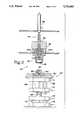
- FIG. 1is a side cutaway view of two halves of an electric motor to be assembled by means of the method and apparatus described herein.
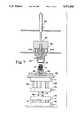
- FIG. 2is a side cutaway view of the motor assembly apparatus of the present invention.
- FIG. 3is a side cutaway view of the motor assembly of FIG. 2 with the motor halves of FIG. 1 installed therein prior to assembly.
- FIG. 4is a side cutaway view of the motor and assembly apparatus of FIG. 3 with the motor shaft alignment piston extended.
- FIG. 5is a side cutaway view of the motor assembly apparatus and motor showing the step of pressing the two halves of the motor assembly together.
- FIG. 6is a side cutaway view of the motor and motor assembly machine of FIG. 5 illustrating the preload position for the motor assembly machine.
- FIG. 7is a side cutaway view of the motor assembly machine and motor llustrating the position of the motor assembly machine when a motor is completely assembled.
- FIG. 8is a partial side cutaway view showing in detail the shaft alignment step of FIG. 4.
- FIG. 9is a partial side cutaway view illustrating in detail the press fitting step of FIG. 5.
- FIG. 10is a partial side cutaway view illustrating in detail the preload step of FIG. 6.
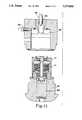
- FIG. 11is a partial side cutaway view illustrating the completed motor assembly shown more generally in FIG. 7.
- an electric motor 10shown in two parts prior to assembly, comprises a hub assembly 12 and a stator assembly 14.
- the stator assembly 14includes a central shaft 16 and stator coils 18 surrounding stator poles 19.
- the shaft 16extends through the stator coils 18 to a connector 20 at which electrical connections are made which provide power and timing signals for control of the motor.
- the shaft assemblyincludes a lower bearing 22 which permits the rotation of a core portion 24 joined to an outer race 26 of the bearing 22.
- the inner race of the bearing 22is joined to the shaft 16.
- the hub assembly 12includes permanent magnet members 30 and a lower flanged portion 32 which will join with the rotary core 24 once the hub assembly 12 is press fitted to the stator assembly 14.
- the hub assemblyincludes an essentially cylindrical housing 34 which is joined to a bearing 36 (hereinafter referred to as "the upper bearing") at its outside race 38.
- the inner race 40 of the upper bearing 36is intended to be joined to the rotor shaft 16 by glue or the like as will be described below.
- a press fit machine 42includes an upper fixture 44 and a lower fixture 46.
- the upper fixture 44includes a vacuum chamber 48 and a source of negative pressure 50 designed to hold the hub assembly 12 in the upper fixture 44 prior to assembly.
- the upper fixture 44also includes a preload weight 52 and preload weight support cylinders 54a and 54b.
- An alignment piston 56is controlled by an alignment cylinder 58.
- the lower press fixture 46includes an upper platform 60 which supports a stationary base 62.
- the stationary base 62is rigid and does not move with respect to the platform 60.
- a cylindrical well inside the base 62holds a spring-loaded chuck 64.
- the platform 60rests on a frame 66 which houses an air intake line 68 and an air outlet line 70 for a press cylinder 72.
- the press cylinder 72is shown in its retracted position, and the direction of air flow is shown by the arrows at the inlet line 68 and the outlet line 70.
- a second frame 74houses air inlet and outlet lines 76 and 78, respectively, of a preload cylinder 80.
- the preload cylinder 80is in the extended position.
- the arrowsshow the direction of air flow.
- the first step in assembling the motor 10is to load the hub assembly 12 into the vacuum chamber 48 of the upper press fixture 44.
- the vacuum line 50is then vacuated which holds the hub assembly 12 in such a way that the preload weight 52 is pushed up by the hub assembly.
- the preload weight 52is supported by a cylinder 82 which encloses the alignment piston 56 and which has a foot 84 of reduced radius that bears directly against the top of the inner race 40 of the upper bearing 36.
- the preload weight 52weighs about three pounds, but the preload weight cylinders 54a and 54b relieve about two pounds of this weight with the result that a one-pound net force rests on the inner race 40.
- the preload weight cylinders 54a,54bare designed to relieve some of the magnetic attraction force otherwise occasioned by the proximity of the permanent magnets 30 to the stator coils 18 as the motor halves are brought together.
- the outer race 38is pulled up with the rest of the hub assembly 12 by the vacuum force 50 to bear against an upper O-ring 86 and a lower O-ring 81.
- the stator assembly 14rests partially on the stationary support 62 and partially on the spring-loaded chuck 64.
- the flanged portion 21has a foot 23 that rests directly on top of the spring-loaded chuck 64.
- the rotary core portion 24also has a foot 25 and this foot nearly rests on top of the stationary support 62, but because the chuck 64 is slightly raised with respect to the support 62, the weight of the core 24 bears down on the outer race 26 of the bearing 22.
- the rotary core 24is connected to the outer race 26 and it rotates with respect to the central section 15.
- FIG. 4shows an expanded view of the apparatus shown in FIG. 8.
- the alignment piston 56extends to engage the center of the shaft 16. This will guide the shaft through the upper bearing 36.
- preload cylinder 80is extended but the press cylinder 72 remains retracted.
- the two halves of the motor 10may be press fitted together.
- the press cylinder 72is extended. This cylinder will push the rotor shaft assembly 14 into the hub assembly 12 until the flanged portion 32 fully engages the stationary support 62. Once this occurs there will be zero pressure on the outlet side 70 of the cylinder 72 and the cylinder will halt.
- gluethat has been placed on the outside of the rotor shaft 16 and on the outside of the rotary support 24 will begin to harden.
- the glueis applied prior to placing the motor 20 in the press fit apparatus. This is an anaerobic glue that will begin to set only when the surfaces to be joined are press fitted together. It is important that the upper and lower bearings remain preloaded with a predetermined amount of force while the hardening of the glue takes place. In order to accomplish this, the vacuum source 50 is turned off and the preload cylinder 80 retracts. At the same time this occurs, the preload weight cylinders 54a and 54b retract allowing the entire amount of the preload weight 52 to be borne by the inner race 40 of the upper bearing 36.
- the weight of the hub assembly which is affixed to the core 24weights the outer race 26 of the lower bearing 22 because the spring-loaded chuck 64 lifts the central section 15 so that the foot of the core 24 is slightly above the stationary support 62.
- the bearingsremain in this preloaded condition for about 15 seconds while the glue sets.
- the press cylinder 72may be retracted allowing the motor to be removed. This resets all cylinders so that the machine is ready for the next motor.
Landscapes
- Engineering & Computer Science (AREA)
- General Engineering & Computer Science (AREA)
- Manufacturing & Machinery (AREA)
- Power Engineering (AREA)
- Mechanical Engineering (AREA)
- Manufacture Of Motors, Generators (AREA)
- Support Of The Bearing (AREA)
Abstract
Description
The present invention relates to a method and apparatus for assembling electric motors and in particular includes a provision for preloading the bearings of the electric motor during assembly.
Electric motors are generally manufactured in two major parts. A rotary hub assembly houses permanent magnet members and encloses a stator assembly which includes stator coils surrounding an electromagnet. The hub assembly is joined to the stator assembly which includes a rotor shaft through upper and lower bearings. The stator assembly shaft is joined to both upper and lower bearings along the inner race of each while the hub is affixed to the outer race of both the upper and lower bearings. When the coils of the stator are energized, the hub assembly and its permanent magnet members will rotate about the shaft.
A particular problem that is encountered in the use of such bearings is that, depending upon how the motor is assembled, the coupling between the rotary hub assembly and the stator assembly can be either too loose or too tight. If the bearings are too loose there is too much play in the hub assembly, and in tightly constructed configurations the hub assembly may actually be impeded in its attempt to rotate properly. On the other hand, if the bearings are too stiff there can be too much friction between the hub assembly and the stator, and the motor will not provide the necessary torque for the particular application.
Heretofore, the bearing stiffness that resulted from the way in which the hub and stator were joined together was largely a matter of chance because there was no attempt made to control the bearing stiffness during assembly. Whether the bearings were preloaded in any way was determined by the orientation of the parts when the glue joining the parts together set. This haphazard approach to motor assembly caused many motors to fail.
The present invention provides a method and apparatus for assembling an electric motor where the motor includes a hub portion having an upper bearing comprising an inside race and an outside race and a shaft assembly portion which includes a rotor shaft extending through a lower bearing where the lower bearing also has an inside race and an outside race. A press fit machine maintains a predetermined amount of preload force on the bearings both while the two motor halves are press fitted together and for a short while afterwards while the glue sets.
According to this method, the hub assembly portion is placed in an upper press fixture and a predetermined preload weight is placed on the inner race of the upper bearing. At the same time the shaft assembly portion with anaerobic glue applied to the shaft is placed in a lower press fixture and a predetermined preload force is maintained on the inner race of the lower bearing. The shaft assembly portion and the hub assembly portion are pressed together by the press fixtures so as to join the two together. The hub portion is then disengaged from the upper press fixture while at the same time a preload weight is maintained on the inner race of the upper bearings for a predetermined period of time and the lower bearing is preloaded by its core weight. After the predetermined period of time the glue sets and the assembled motor is removed from the press fitting machine.
The press fitting machine includes a preload weight which is supported by support cylinders which are selectively actuated to allow the preload weight to rest on the inner race of the upper bearing. The lower fixture of the press fitting machine includes a spring-loaded mounting base which allows the weight of the core of the stator assembly to preload the lower bearing. The lower press fitting includes a spring-loaded chuck that raises the shaft slightly so that the core weight is suspended by the outer race of the lower bearing. The upper press fitting includes a vacuum chamber for holding the hub assembly and further includes an alignment piston for aligning the shaft of the stator assembly with the center of the hub assembly to guide the shaft through the upper bearing. A preload weight is supported on a cylinder that surrounds the alignment piston and which bears against the inner race of the upper bearing.
This apparatus insures that a preload force is maintained on the inner races of the upper and lower bearings during motor assembly. Once the motor is assembled it will be neither too loose nor too stiff as a result of the aforementioned preload being maintained during manufacture, before the glue joining the upper and lower halves of the motor has had time to set. Once the glue sets, the bearings will have the proper degree of stiffness.
FIG. 1 is a side cutaway view of two halves of an electric motor to be assembled by means of the method and apparatus described herein.
FIG. 2 is a side cutaway view of the motor assembly apparatus of the present invention.
FIG. 3 is a side cutaway view of the motor assembly of FIG. 2 with the motor halves of FIG. 1 installed therein prior to assembly.
FIG. 4 is a side cutaway view of the motor and assembly apparatus of FIG. 3 with the motor shaft alignment piston extended.
FIG. 5 is a side cutaway view of the motor assembly apparatus and motor showing the step of pressing the two halves of the motor assembly together.
FIG. 6 is a side cutaway view of the motor and motor assembly machine of FIG. 5 illustrating the preload position for the motor assembly machine.
FIG. 7 is a side cutaway view of the motor assembly machine and motor llustrating the position of the motor assembly machine when a motor is completely assembled.
FIG. 8 is a partial side cutaway view showing in detail the shaft alignment step of FIG. 4.
FIG. 9 is a partial side cutaway view illustrating in detail the press fitting step of FIG. 5.
FIG. 10 is a partial side cutaway view illustrating in detail the preload step of FIG. 6.
FIG. 11 is a partial side cutaway view illustrating the completed motor assembly shown more generally in FIG. 7.
Referring to FIG. 1, anelectric motor 10, shown in two parts prior to assembly, comprises ahub assembly 12 and astator assembly 14. Thestator assembly 14 includes acentral shaft 16 andstator coils 18 surroundingstator poles 19. Theshaft 16 extends through thestator coils 18 to aconnector 20 at which electrical connections are made which provide power and timing signals for control of the motor. The shaft assembly includes alower bearing 22 which permits the rotation of acore portion 24 joined to anouter race 26 of thebearing 22. The inner race of thebearing 22 is joined to theshaft 16.
Thehub assembly 12 includespermanent magnet members 30 and a lower flangedportion 32 which will join with therotary core 24 once thehub assembly 12 is press fitted to thestator assembly 14. The hub assembly includes an essentiallycylindrical housing 34 which is joined to a bearing 36 (hereinafter referred to as "the upper bearing") at itsoutside race 38. Theinner race 40 of the upper bearing 36 is intended to be joined to therotor shaft 16 by glue or the like as will be described below.
Referring to FIG. 2, apress fit machine 42 includes anupper fixture 44 and alower fixture 46. Theupper fixture 44 includes avacuum chamber 48 and a source ofnegative pressure 50 designed to hold thehub assembly 12 in theupper fixture 44 prior to assembly. Theupper fixture 44 also includes apreload weight 52 and preloadweight support cylinders alignment piston 56 is controlled by analignment cylinder 58.
Thelower press fixture 46 includes anupper platform 60 which supports astationary base 62. Thestationary base 62 is rigid and does not move with respect to theplatform 60. A cylindrical well inside thebase 62 holds a spring-loadedchuck 64. Theplatform 60 rests on aframe 66 which houses anair intake line 68 and anair outlet line 70 for apress cylinder 72. In FIG. 2 thepress cylinder 72 is shown in its retracted position, and the direction of air flow is shown by the arrows at theinlet line 68 and theoutlet line 70. Asecond frame 74 houses air inlet andoutlet lines preload cylinder 80. In FIG. 2, thepreload cylinder 80 is in the extended position. The arrows show the direction of air flow.
Referring now to FIG. 3, the first step in assembling themotor 10 is to load thehub assembly 12 into thevacuum chamber 48 of theupper press fixture 44. Thevacuum line 50 is then vacuated which holds thehub assembly 12 in such a way that thepreload weight 52 is pushed up by the hub assembly. This is shown in more detail in FIG. 8. Thepreload weight 52 is supported by acylinder 82 which encloses thealignment piston 56 and which has afoot 84 of reduced radius that bears directly against the top of theinner race 40 of theupper bearing 36. Thepreload weight 52 weighs about three pounds, but thepreload weight cylinders inner race 40. This preloads the bearing 36 while the two motor halves are being assembled, and prevents theshaft 16 from knocking thebearing 36 out of alignment. Also, thepreload weight cylinders permanent magnets 30 to the stator coils 18 as the motor halves are brought together. Theouter race 38 is pulled up with the rest of thehub assembly 12 by thevacuum force 50 to bear against an upper O-ring 86 and a lower O-ring 81.
Thestator assembly 14 rests partially on thestationary support 62 and partially on the spring-loadedchuck 64. Acentral section 15, which includes theshaft 16 and theconnector 20, also includes aflanged portion 21 which supports theinner race 28 of thebearing 22. As FIG. 8 shows, theflanged portion 21 is relieved radially outwardly of theinner race 28 so that it does no bear against the outer race of thebearing 26. Theflanged portion 21 has afoot 23 that rests directly on top of the spring-loadedchuck 64. Therotary core portion 24 also has afoot 25 and this foot nearly rests on top of thestationary support 62, but because thechuck 64 is slightly raised with respect to thesupport 62, the weight of the core 24 bears down on theouter race 26 of thebearing 22. Therotary core 24 is connected to theouter race 26 and it rotates with respect to thecentral section 15.
FIG. 4 shows an expanded view of the apparatus shown in FIG. 8. In FIG. 4 thealignment piston 56 extends to engage the center of theshaft 16. This will guide the shaft through theupper bearing 36. At thistime preload cylinder 80 is extended but thepress cylinder 72 remains retracted.
Referring now to FIGS. 5 and 9, once thealignment cylinder 58 has caused thealignment piston 56 to engage theshaft 16, the two halves of themotor 10 may be press fitted together. In order to do this, thepress cylinder 72 is extended. This cylinder will push therotor shaft assembly 14 into thehub assembly 12 until theflanged portion 32 fully engages thestationary support 62. Once this occurs there will be zero pressure on theoutlet side 70 of thecylinder 72 and the cylinder will halt.
Once the two halves of the motor are press fitted together, glue that has been placed on the outside of therotor shaft 16 and on the outside of therotary support 24 will begin to harden. The glue is applied prior to placing themotor 20 in the press fit apparatus. This is an anaerobic glue that will begin to set only when the surfaces to be joined are press fitted together. It is important that the upper and lower bearings remain preloaded with a predetermined amount of force while the hardening of the glue takes place. In order to accomplish this, thevacuum source 50 is turned off and thepreload cylinder 80 retracts. At the same time this occurs, thepreload weight cylinders preload weight 52 to be borne by theinner race 40 of theupper bearing 36. With thepreload cylinder 80 retracted, the weight of the hub assembly which is affixed to the core 24 weights theouter race 26 of thelower bearing 22 because the spring-loadedchuck 64 lifts thecentral section 15 so that the foot of thecore 24 is slightly above thestationary support 62. The bearings remain in this preloaded condition for about 15 seconds while the glue sets. Finally, as shown in FIGS. 11 and 7, thepress cylinder 72 may be retracted allowing the motor to be removed. This resets all cylinders so that the machine is ready for the next motor.
The terms and expressions which have been employed in the foregoing specification are used therein as terms of description and not of limitation, and there is no intention, in the use of such terms and expressions, of excluding equivalents of the features shown and described or portions thereof, it being recognized that the scope of the invention is defined and limited only by the claims which follow.
Claims (12)
1. A method of assembling an electric motor, said motor including a hub assembly portion having an upper bearing, said bearing having an inside race and an outside race, and a stator assembly portion having a rotor shaft extending through a lower bearing, said lower bearing having an inside race and an outside race, comprising the steps of:
(a) placing the hub assembly portion in a first press fixture;
(b) placing the stator assembly portion in a second press fixture;
(c) impressing a first preload force on the upper bearing of the hub assembly portion;
(d) impressing a second preload force on the lower bearing of the stator assembly portion;
(e) pressing the first and second press fixtures together thereby joining the hub assembly portion to the stator assembly portion; and
(f) maintaining third and fourth preload forces, respectively, on the upper and lower bearings for a predetermined period of time.
2. The method of claim 1 wherein at least a portion of said first and second preload forces are maintained on their respective bearings during step (e).
3. The method of claim 1 wherein the first preload force is impressed on the inner race of the upper bearing.
4. The method of claim 3 wherein the second preload force is impressed on the outer race of the lower bearing.
5. The method of claim 1 wherein the third preload force is maintained on the inner race of the upper bearing and the fourth preload force is maintained on the outer race of the lower bearing.
6. The method of claim 1 further including the step of applying an anaerobic glue to selected surfaces of the hub portion and the stator portion prior to executing step (a).
7. The method of claim 6 wherein the predetermined period of time of step (f) is selected to be sufficiently long to allow the anaerobic glue to cure.
8. A press fit machine for assembling an electric motor, said electric motor including a hub portion having an upper bearing and a stator portion having a lower bearing. Said upper bearing and said lower bearing each including an inside race and an outside race, respectively comprising:
(a) an upper fixture for holding the hub portion, said upper fixture including means for impressing a preload force on the upper bearing;
(b) a lower press fit fixture for holding the stator portion, said lower fixture including means for impressing a preload force on the lower bearing;
(c) a press cylinder for pushing the upper and lower fixtures together; and
(d) means for holding said respective upper and lower bearings in a preloaded condition for a predetermined period of
time subsequent to pushing the upper and lower fixtures together.
9. The press fit machine of claim 1 wherein the means for impressing a preload force on the upper bearing includes a preload weight which bears against an inner race of said upper bearing.
10. The press fit machine of claim 8 wherein said stator assembly comprises a central section including a shaft journalled through said lower bearing and affixed to an inner race thereof and a rotary core portion affixed to an outer race of said lower bearing, the central section of said stator assembly being held in a chuck in the lower press fit fixture whereby the weight of the rotary core impresses the preload force on said outer race of said lower bearing.
11. The press fit machine of claim 9 further including preload weight support cylinders for relieving at least a portion of said preload weight while said upper and lower press fit fixtures are pushed together with the press cylinder.
12. The press fit machine of claim 8 wherein said upper press fit fixture includes vacuum means for holding the hub portion therein prior to assembly of the electric motor.
Priority Applications (2)
| Application Number | Priority Date | Filing Date | Title |
|---|---|---|---|
| US08/014,342US5272803A (en) | 1993-02-05 | 1993-02-05 | Method and apparatus for electric motor assembly with bearing preload |
| JP5278281AJPH06284647A (en) | 1993-02-05 | 1993-11-08 | Electric motor assembly method |
Applications Claiming Priority (1)
| Application Number | Priority Date | Filing Date | Title |
|---|---|---|---|
| US08/014,342US5272803A (en) | 1993-02-05 | 1993-02-05 | Method and apparatus for electric motor assembly with bearing preload |
Publications (1)
| Publication Number | Publication Date |
|---|---|
| US5272803Atrue US5272803A (en) | 1993-12-28 |
Family
ID=21764902
Family Applications (1)
| Application Number | Title | Priority Date | Filing Date |
|---|---|---|---|
| US08/014,342Expired - LifetimeUS5272803A (en) | 1993-02-05 | 1993-02-05 | Method and apparatus for electric motor assembly with bearing preload |
Country Status (2)
| Country | Link |
|---|---|
| US (1) | US5272803A (en) |
| JP (1) | JPH06284647A (en) |
Cited By (18)
| Publication number | Priority date | Publication date | Assignee | Title |
|---|---|---|---|---|
| US5736879A (en)* | 1996-02-02 | 1998-04-07 | Siliconix Incorporated | Closed-loop frequency-to-current converter with integrable capacitances |
| US5767643A (en)* | 1996-02-02 | 1998-06-16 | Siliconix Incorporated | Commutation delay generator for a multiphase brushless DC motor |
| US5825145A (en)* | 1995-12-18 | 1998-10-20 | Siliconix Incorporated | Quiet commutation circuit for an electric motor |
| US5977673A (en)* | 1996-08-08 | 1999-11-02 | Mitsuba Corporation | Armature shaft support structure for use in an electric motor |
| US6122817A (en)* | 1997-09-19 | 2000-09-26 | Alliedsignal Inc. | Rotor assembly having lamination stack that is separately piloted and clamped |
| US6148501A (en)* | 1998-04-14 | 2000-11-21 | Seagate Technology Llc | Fabrication means for in-hub spindle with separate fluid dynamic bearings |
| FR2806222A1 (en)* | 2000-03-07 | 2001-09-14 | Moriyama Ind | ASSEMBLY DEVICE FOR A MOTOR HAVING PERMANENTLY MAGNETIZED INDUCING MAGNETS |
| US20030150103A1 (en)* | 2002-02-08 | 2003-08-14 | Yuji Yasuda | Motor assembling apparatus |
| US20050050723A1 (en)* | 2003-09-10 | 2005-03-10 | Minebea Co., Ltd. | Device to press the shaft of a rotor into a stator housing |
| EP1536545A2 (en) | 2003-11-28 | 2005-06-01 | Koyo Seiko Co., Ltd. | Electric motor, electric motor manufacturing method, and electric motor manufacturing device |
| US20050275298A1 (en)* | 2004-05-26 | 2005-12-15 | Danfoss Compressors Gmbh | Method for mounting a drive shaft of a compressor |
| WO2006032587A1 (en)* | 2004-09-21 | 2006-03-30 | Robert Bosch Gmbh | Electric machine |
| US20070011865A1 (en)* | 2003-01-24 | 2007-01-18 | Delta Electronics Inc. | Method and Fixture for Assembling Supporting Disk of Motor Rotor |
| CN102790479A (en)* | 2012-08-13 | 2012-11-21 | 宁波沃特美逊机器人科技有限公司 | Motor rotor bearing assembly machine |
| US20130174402A1 (en)* | 2012-01-10 | 2013-07-11 | Soeren Juul Jensen | Generator assembly apparatus |
| US9109589B2 (en) | 2010-02-25 | 2015-08-18 | Mitsubishi Heavy Industries, Ltd. | Electric compressor and assembly method thereof |
| US10673297B2 (en) | 2017-12-11 | 2020-06-02 | Mcmillan Electric Company | Impact resistant electric motor |
| IT202000002719A1 (en)* | 2020-02-12 | 2021-08-12 | Hydra S R L | BUSHING DEVICE |
Families Citing this family (1)
| Publication number | Priority date | Publication date | Assignee | Title |
|---|---|---|---|---|
| JP4500272B2 (en)* | 2006-01-24 | 2010-07-14 | 本田技研工業株式会社 | Method and apparatus for assembling rotating electrical machine |
Citations (2)
| Publication number | Priority date | Publication date | Assignee | Title |
|---|---|---|---|---|
| US3538598A (en)* | 1968-09-23 | 1970-11-10 | Emerson Electric Co | Method for assembly of ball bearing electric motors |
| US4048717A (en)* | 1976-04-29 | 1977-09-20 | Unipas, Inc. | Apparatus for assembling an encapsulated wet motor circulator |
- 1993
- 1993-02-05USUS08/014,342patent/US5272803A/ennot_activeExpired - Lifetime
- 1993-11-08JPJP5278281Apatent/JPH06284647A/enactivePending
Patent Citations (2)
| Publication number | Priority date | Publication date | Assignee | Title |
|---|---|---|---|---|
| US3538598A (en)* | 1968-09-23 | 1970-11-10 | Emerson Electric Co | Method for assembly of ball bearing electric motors |
| US4048717A (en)* | 1976-04-29 | 1977-09-20 | Unipas, Inc. | Apparatus for assembling an encapsulated wet motor circulator |
Cited By (31)
| Publication number | Priority date | Publication date | Assignee | Title |
|---|---|---|---|---|
| US5825145A (en)* | 1995-12-18 | 1998-10-20 | Siliconix Incorporated | Quiet commutation circuit for an electric motor |
| US5767643A (en)* | 1996-02-02 | 1998-06-16 | Siliconix Incorporated | Commutation delay generator for a multiphase brushless DC motor |
| US5955903A (en)* | 1996-02-02 | 1999-09-21 | Siliconix Incorporated | Folded ramp capacitance circuit with current source and comparator circuit |
| US5736879A (en)* | 1996-02-02 | 1998-04-07 | Siliconix Incorporated | Closed-loop frequency-to-current converter with integrable capacitances |
| US5977673A (en)* | 1996-08-08 | 1999-11-02 | Mitsuba Corporation | Armature shaft support structure for use in an electric motor |
| US6122817A (en)* | 1997-09-19 | 2000-09-26 | Alliedsignal Inc. | Rotor assembly having lamination stack that is separately piloted and clamped |
| US6148501A (en)* | 1998-04-14 | 2000-11-21 | Seagate Technology Llc | Fabrication means for in-hub spindle with separate fluid dynamic bearings |
| US6739034B2 (en) | 2000-03-07 | 2004-05-25 | Kabushiki Kaisha Moric | Assembling apparatus for electrical machine having permanently magnetized field magnets |
| FR2806222A1 (en)* | 2000-03-07 | 2001-09-14 | Moriyama Ind | ASSEMBLY DEVICE FOR A MOTOR HAVING PERMANENTLY MAGNETIZED INDUCING MAGNETS |
| US6807724B2 (en)* | 2002-02-08 | 2004-10-26 | Mitsuba Corporation | Motor assembling apparatus |
| US20030150103A1 (en)* | 2002-02-08 | 2003-08-14 | Yuji Yasuda | Motor assembling apparatus |
| CN1319252C (en)* | 2002-02-08 | 2007-05-30 | 株式会社美姿把 | Motor assembling apparatus |
| US20070011865A1 (en)* | 2003-01-24 | 2007-01-18 | Delta Electronics Inc. | Method and Fixture for Assembling Supporting Disk of Motor Rotor |
| US20050050723A1 (en)* | 2003-09-10 | 2005-03-10 | Minebea Co., Ltd. | Device to press the shaft of a rotor into a stator housing |
| US7415758B2 (en)* | 2003-09-10 | 2008-08-26 | Minebea Co., Ltd. | Device to press the shaft of a rotor into a stator housing |
| US20080066292A1 (en)* | 2003-11-28 | 2008-03-20 | Ken Matsubara | Electric motor, electric motor manufacturing method, and electric motor manufacturing device |
| EP1536545A2 (en) | 2003-11-28 | 2005-06-01 | Koyo Seiko Co., Ltd. | Electric motor, electric motor manufacturing method, and electric motor manufacturing device |
| US20050116563A1 (en)* | 2003-11-28 | 2005-06-02 | Ken Matsubara | Electric motor, electric motor manufacturing method, and electric motor manufacturing device |
| EP1536545A3 (en)* | 2003-11-28 | 2006-11-15 | JTEKT Corporation | Electric motor, electric motor manufacturing method, and electric motor manufacturing device |
| US20080066301A1 (en)* | 2003-11-28 | 2008-03-20 | Ken Matsubara | Electric motor, electric motor manufacturing method, and electric motor manufacturing device |
| US20050275298A1 (en)* | 2004-05-26 | 2005-12-15 | Danfoss Compressors Gmbh | Method for mounting a drive shaft of a compressor |
| US7478471B2 (en)* | 2004-05-26 | 2009-01-20 | Danfoss Compressors Gmbh | Method for mounting a drive shaft of a compressor |
| US20080093937A1 (en)* | 2004-09-21 | 2008-04-24 | Robert Bosch Gmbh | Electrical Machine |
| WO2006032587A1 (en)* | 2004-09-21 | 2006-03-30 | Robert Bosch Gmbh | Electric machine |
| US9109589B2 (en) | 2010-02-25 | 2015-08-18 | Mitsubishi Heavy Industries, Ltd. | Electric compressor and assembly method thereof |
| US20130174402A1 (en)* | 2012-01-10 | 2013-07-11 | Soeren Juul Jensen | Generator assembly apparatus |
| US9764434B2 (en)* | 2012-01-10 | 2017-09-19 | Siemens Aktiengesellschaft | Generator assembly apparatus |
| CN102790479A (en)* | 2012-08-13 | 2012-11-21 | 宁波沃特美逊机器人科技有限公司 | Motor rotor bearing assembly machine |
| CN102790479B (en)* | 2012-08-13 | 2016-01-20 | 宁波沃特美逊机器人科技有限公司 | A kind of rotor bearing assembly machine |
| US10673297B2 (en) | 2017-12-11 | 2020-06-02 | Mcmillan Electric Company | Impact resistant electric motor |
| IT202000002719A1 (en)* | 2020-02-12 | 2021-08-12 | Hydra S R L | BUSHING DEVICE |
Also Published As
| Publication number | Publication date |
|---|---|
| JPH06284647A (en) | 1994-10-07 |
Similar Documents
| Publication | Publication Date | Title |
|---|---|---|
| US5272803A (en) | Method and apparatus for electric motor assembly with bearing preload | |
| US4128935A (en) | Assembly method for a motor | |
| US6439774B1 (en) | Rotary air bearing and process for manufacturing the same | |
| EP1367699A2 (en) | Method and apparatus for manufacturing electric motor | |
| US4031610A (en) | Method of assembly of dynamoelectric machines | |
| US5574323A (en) | Electronically commutated electric motor for driving a feed pump | |
| US20050116563A1 (en) | Electric motor, electric motor manufacturing method, and electric motor manufacturing device | |
| EP3896301B1 (en) | Assembly method for high-speed rotor | |
| PL319484A1 (en) | Integrated disc hub and camp in the disc storage drive | |
| US5801467A (en) | Electric motor for a drive mechanism in particular, a pump | |
| KR102632406B1 (en) | Rotor for elecric motor, electric motor having the same, supercharger having electric motor, and assembling method for electric motor | |
| CA2315305A1 (en) | Method and apparatus for centering a generator stator and rotor | |
| JPH025663Y2 (en) | ||
| JPH1066312A (en) | Permanent magnet type synchronous motor assembly equipment | |
| CA1191536A (en) | Motor having stationary shaft and method of assembling it | |
| CN211728944U (en) | Disc type motor stator preassembling clamp | |
| JP2865562B2 (en) | Method and apparatus for coating rotor magnet | |
| US3753281A (en) | Means and method for aligning motor assembly | |
| EP0953668B1 (en) | Method for mounting of a drive motor on a laundry treatment apparatus | |
| CA1333083C (en) | Method and apparatus for making a permanent magnet rotor, and a rotor made thereby | |
| CN219999198U (en) | Magnetic gear stator assembly fixture | |
| EP0886365A1 (en) | Method of assembling electric motors with ball bearings to minimize preload variation | |
| CN119748104B (en) | Automatic assembling equipment and assembling method for cooling fan | |
| JPH08228465A (en) | Spindle motor | |
| CN100427785C (en) | Methods used to assemble bearings |
Legal Events
| Date | Code | Title | Description |
|---|---|---|---|
| AS | Assignment | Owner name:SYNEKTRON CORPORATION, OREGON Free format text:ASSIGNMENT OF ASSIGNORS INTEREST.;ASSIGNORS:HARRISON, RICHARD;SUN, LEI;REEL/FRAME:006429/0858 Effective date:19930128 | |
| STCF | Information on status: patent grant | Free format text:PATENTED CASE | |
| CC | Certificate of correction | ||
| FPAY | Fee payment | Year of fee payment:4 | |
| AS | Assignment | Owner name:SAE MAGNETICS (H.K.) LTD., A HONG KONG CORP., CALI Free format text:ASSIGNMENT OF ASSIGNORS INTEREST;ASSIGNOR:SYNEKTRON CORPORATION;REEL/FRAME:008732/0820 Effective date:19970912 | |
| FPAY | Fee payment | Year of fee payment:8 | |
| FPAY | Fee payment | Year of fee payment:12 | |
| AS | Assignment | Owner name:SAE MAGNETICS (HK) LTD., HONG KONG Free format text:CHANGE OF ADDRESS;ASSIGNOR:SAE MAGNETICS (H.K.) LTD.;REEL/FRAME:017656/0312 Effective date:20060421 |