US5272647A - Valve diagnostic apparatus and method - Google Patents
Valve diagnostic apparatus and methodDownload PDFInfo
- Publication number
- US5272647A US5272647AUS07/647,737US64773791AUS5272647AUS 5272647 AUS5272647 AUS 5272647AUS 64773791 AUS64773791 AUS 64773791AUS 5272647 AUS5272647 AUS 5272647A
- Authority
- US
- United States
- Prior art keywords
- valve
- actuator
- test
- unit
- positioner
- Prior art date
- Legal status (The legal status is an assumption and is not a legal conclusion. Google has not performed a legal analysis and makes no representation as to the accuracy of the status listed.)
- Expired - Fee Related
Links
- 238000000034methodMethods0.000titleclaimsdescription29
- 238000012360testing methodMethods0.000claimsabstractdescription65
- 239000012530fluidSubstances0.000claimsabstractdescription39
- 230000036962time dependentEffects0.000claimsabstractdescription29
- 230000008569processEffects0.000claimsdescription16
- 238000007789sealingMethods0.000claimsdescription14
- 238000005259measurementMethods0.000claimsdescription12
- 230000009471actionEffects0.000claimsdescription3
- 238000012545processingMethods0.000claimsdescription3
- 238000004886process controlMethods0.000claims11
- 230000006870functionEffects0.000abstractdescription6
- 230000000694effectsEffects0.000abstractdescription2
- 238000006073displacement reactionMethods0.000description7
- 230000006399behaviorEffects0.000description3
- 230000008901benefitEffects0.000description3
- 238000003745diagnosisMethods0.000description3
- 230000005540biological transmissionEffects0.000description2
- 230000001419dependent effectEffects0.000description2
- 230000001131transforming effectEffects0.000description2
- 238000013459approachMethods0.000description1
- 230000003190augmentative effectEffects0.000description1
- 230000003542behavioural effectEffects0.000description1
- 238000009530blood pressure measurementMethods0.000description1
- 230000015556catabolic processEffects0.000description1
- 238000006243chemical reactionMethods0.000description1
- 238000004891communicationMethods0.000description1
- 238000006731degradation reactionMethods0.000description1
- 238000012631diagnostic techniqueMethods0.000description1
- 230000000977initiatory effectEffects0.000description1
- 239000000463materialSubstances0.000description1
- 238000012986modificationMethods0.000description1
- 230000004048modificationEffects0.000description1
- 238000012544monitoring processMethods0.000description1
- 230000002093peripheral effectEffects0.000description1
- 238000007670refiningMethods0.000description1
- 238000011144upstream manufacturingMethods0.000description1
Images

Classifications
- F—MECHANICAL ENGINEERING; LIGHTING; HEATING; WEAPONS; BLASTING
- F16—ENGINEERING ELEMENTS AND UNITS; GENERAL MEASURES FOR PRODUCING AND MAINTAINING EFFECTIVE FUNCTIONING OF MACHINES OR INSTALLATIONS; THERMAL INSULATION IN GENERAL
- F16K—VALVES; TAPS; COCKS; ACTUATING-FLOATS; DEVICES FOR VENTING OR AERATING
- F16K37/00—Special means in or on valves or other cut-off apparatus for indicating or recording operation thereof, or for enabling an alarm to be given
- F16K37/0075—For recording or indicating the functioning of a valve in combination with test equipment
- F16K37/0083—For recording or indicating the functioning of a valve in combination with test equipment by measuring valve parameters
Definitions
- the present inventionrelates to valve diagnostics, and more particularly, to the diagnosis of valves that are installed in process plant flow lines.
- solenoid and control valvesare typically present in process plants dedicated, for example, to producing electrical power, refining materials, or producing food. In many such plants, reliable valve operation not only affects the efficiency of the process or the quality of the product, but may also have severe safety consequences. Safety considerations are particularly relevant in nuclear power plants.
- reliabilityrefers not only to the availability of the valve to operate when actuated, but also the effectiveness of the operation, i.e., stroking from a fully open to a fully closed position when energized within specified limits.
- a known approach to such diagnosticsincludes energizing the valve while obtaining accurate measurements of, for example, stem thrust or displacement.
- stem thrustmovement, or similar dependent variable
- independent energizing variablesuch as electric current, hydraulic pressure, or pneumatic pressure in the actuator
- certain valve behaviors indicative of reliabilitycan be inferred.
- diagnostic techniquesrely on actuation of the valve by the positioner and energy source that are associated with the valve during normal operation.
- the behavior of the independent variablee.g., actuator fluid pressure
- an object of the present inventionto provide a system and method for testing a valve in a process plant flow line, whereby the valve actuator can be controlled during the test, independently of the controller that is normally associated with the valve positioner.
- a valve test unit in accordance with the inventionincludes a first input port connectable to a source of fluid pressure, and a second input port connectable to a source of electrical power.
- the unithas a first output port fluidly connected to the first input port, for delivering a controlled fluid pressure from the unit to the valve actuator.
- a second output portis electrically connected to the second input port, for delivering a controlled electrical signal from the unit to the valve positioner.
- the unitincludes a test program and associated hardware for transforming the source pressure at the first input port into a controlled, time dependent fluid pressure at the first output port, and transforming the electrical power source at the second input port into a controlled, time dependent electrical signal at the second output port.
- the test unitis positioned in the vicinity of the valve, and one or both of the first and second output ports is connected to the valve actuator and valve positioner, respectively. If program control of the actuator pressure is desired while bypassing the positioner, the first output port is connected to the actuator, and the fluid pressure in the actuator is controlled in accordance with the time dependence specified by the first program.
- the second output portis connected to the normal valve positioner, and the second program is selected to specify a predetermined, time-dependent electrical signal as an input to the positioner, which in turn delivers a time-dependent fluid pressure to the valve actuator.
- a significant advantage of the present inventionis that a portable testing unit can selectively energize the actuator directly with a program-controlled, time-dependent fluid pressure delivered directly from the unit to the actuator, thereby bypassing the normal controller and positioner. Another time-dependent actuation can be achieved by substituting an electrical control signal from the second output port of the unit, for the control signal from the normal valve controller, whereby the normal positioner is controlled from the test unit. Either of these test arrangements can be useful for obtaining significant behavioral characteristics of the valve. If both testing arrangements are utilized for a given valve, differences in valve behavior resulting from programmed control intended to produce identical actuator energizing, can reveal potential problems in the positioner, the pressure and electrical sources for the positioner, or in equipment associated with the controller, upstream of the positioner.
- the test unitalso serves as a device for making and/or recording measurements uniquely associated with the valve test. These include stem thrust or displacement, actuator pressure, and other electrical and pressure signals which may be necessary or desirable for a thorough diagnostic analysis of the valve or valve system.
- the test unit in accordance with the inventionthus has the capability to control a valve electrically, with either a program voltage or current versus time, or to drive the valve by fluid pressure, e.g., pneumatically.
- the desired driving functionis programmed into the computer associated with the base unit.
- the test unitfunctions on a temporary basis, as a valve positioner for test purposes.
- the test unitis also adapted to receive and store pneumatic and electrical measurement data.
- auxiliary unitpreferably used in conjunction with the inventive test unit summarized above, a relatively large number of electrical signals (current or voltage) in a pneumatic or hydraulic control loop of the valve, can be monitored.
- Thisincludes but is not limited to signals associated with E/P or I/P positioners, solenoids, limit switches, position indicators and controllers.
- the usermay temporarily install and monitor a variety of instruments to assist in monitoring valve performance. These include strain gauges, load cells, accelerometers, and thermocouples.
- the base test unitpreferably includes a sufficient number of electrical input ports and appropriate recording channels to permit the user to obtain significantly more data than had previously been acquired for valve diagnosis in the field, this capability is augmented by the auxiliary unit, which has the capability to monitor additional pneumatic and hydraulic pressures remote from the base unit.
- the auxiliary unitincludes several pressure transducers which tie into the base unit.
- multiple pressure signalspneumatic or hydraulic
- the auxiliary unitcan be tied in closer to the pressure source to reduce pressure lag, relative to a direct connection to the base unit.
- the auxiliary unitalso allows for conversion of current signals into voltage signals for delivery to voltage sensitive ports in the base unit.
- FIG. 1is a schematic of the test unit of the invention, installed at a valve as part of a more comprehensive valve diagnostic system;
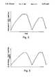
- FIG. 2is a graphic representation of a pneumatic test control signal delivered from the test unit to the valve actuator.
- FIG. 3is a graphic representation of an electrical test control signal delivered from the test unit to the valve positioner.
- FIG. 1is a schematic representation of the invention installed at part of a system 10 for acquiring data from valves 12,14.
- valves 12,14For convenience, structures found on both valves have been given the same numeric identifier, except that those associated with valve 12 will have the suffix "a" and those associated with valve 14, "b". When similar structures on both valves are referenced, the suffix will not be used.
- These valvesmay be of substantially any type, and in any event would include a valve body 16a,16b which has a flow bore (not shown) in fluid communication with the respective process flow line 18. It will be understood that each valve has means within the body for sealing the flow bore against flow.
- a stem, shaft, or similar transmission element 22(hereinafter generally referred to as "stem") is moved by the valve actuator 20, whereby the stem 22 positions the sealing member within the valve body between open and closed flow conditions.
- each valveincludes an associated positioner 24 which has an output line 26 through which fluid pressure is delivered at a controlled rate to the respective actuator 20.
- the positioner inputswould, in the case of a pneumatic valve, include a source of compressed air 28, and a source of electric power 30.
- a valve controller 34via an electrical line 32.
- the controlleris typically remote from the positioner 24, e.g., the controller 34 is in the plant central control room, whereas the positioner 24 is on or at the valve.
- the positioner 24receives as an input, a signal from line 25, commensurate with the position of the stem 22.
- the position data from input 25are compared with the demand or desired position from signal 32, according to conventional logic within positioner 24, whereby the appropriate pressure is delivered to actuator on line 26.
- a diagnostic or test base unit 100is connectable to at least one valve 12, for superseding or overriding the controller 34 and/or positioner 24, whereby the valve can be actuated according to a predetermined, time-dependent program.
- the base unit 100has a first input port 102 connectable to a source 104 of fluid pressure, e.g., compressed air.
- a source 104 of fluid pressuree.g., compressed air.
- This sourcemay either be transported to the vicinity of the valve along with the base unit 100, or, in a more typical situation, source line 104 is connected to air pressure lines that are available throughout the process plant.
- a second input port 106is connectable to a source of electrical power 108, such as an electrical outlet in the plant.
- the base unit 100has a first output port 110 that is fluidly connected within the unit to port 102, for delivering a controlled fluid pressure from the unit along line 112.
- Line 112is selectively connectable to line 26, i.e., directly to actuator 20, downstream of positioner 24a.
- a second output port 114is electrically connected within the base unit to the second input port 106, for delivering a controlled electrical signal from the unit on electric line 116.
- the control signal on line 116emulates the control signal normally provided by controller 34 along line 32a.
- the unit 100includes test program means for converting the fluid pressure at the first input port 102 into a controlled, time-dependent fluid pressure at the first output port 110, and for converting electrical power at the second input port 106 into a controlled, time-dependent electrical signal at the second output port 114.
- the test program meanscan include conventional transformer hardware with dials or the like, whereby the operator can vary the outputs at ports 110,114 manually.
- predetermined, time-dependent output pressures and voltages at ports 110,114are specified by several different converter or transformer paths within the unit, with switches whereby the operator can select one of the plurality of "hard wired" pressure and electrical test programs.
- a computer 118which may be integral with or separate from the base unit 100, specifies the test programs.
- the term "computer”is intended to mean a programmable microprocessor, with or without associated peripherals such as a digital mass storage device, keyboard and display, or equivalent interfaces.
- the important aspect of the computer 118 as used in the preferred embodiment of the present inventionis that a time-dependent fluid pressure, and a time-dependent electrical signal, are independently specified and output from the unit 100 as a result of test programs that are stored in, and executed by, the digital processing means associated with the unit.
- a portable base unit 100 and associated digital processor 118are positioned in the vicinity of a valve 12 to be tested.
- Actuator 20afor operating the valve, can be energized in the most straightforward manner by connecting pneumatic line 112 from port 110 directly to the actuator 20, typically through a T fitting in line 26a.
- the positioner 24ais then overridden or otherwise deactivated by any of a variety of available techniques such as shutting off air and electrical sources 28a,30a, or sending an appropriate signal along line 32a from the controller 34.
- the actuator 20ais energized solely and directly by the pressure in line 112, which has a time-dependence specified independently of the controller 34, by the test program stored or otherwise defined by the unit 100.
- a significant advantage of energizing the actuator 20a via the test program and line 112is that a time-dependent energizing that would not ordinarily be useful for flow control purposes, but which would be revealing of information useful for diagnostic purposes, can be achieved with the present invention, without modification of the normal control algorithm in controller 34.
- the operatorcan select either a known, stored program for execution of the pressure control on line 112, or the operator can modify (and reproduce) the pressure amplitude, or time dependency during the course of performing a sequence of valve energizing cycles.
- the information flow along line 119can flow between a base unit and distinct computer 118 as shown in FIG. 1, or the flow can be entirely within the base unit if the computer is incorporated therein.
- the unit 100is used in conjunction with a direct measurement of the actuator pressure P1 at 122, and the direct measurement of stem movement as manifested by a sensor voltage E1 at 120.
- the base unit 100includes a measurement input section 124 having a plurality of pressure input ports such as 126,128.
- Line 122is directly attached to actuator 20a, and directly connected to measurement port 126.
- Pressure transducers internal to the base unit 100convert pressure variations into measured values which are recorded, preferably on magnetic memory or the like associated with computer 118.
- Base unit 100also preferably includes an electrical measurement input section 130 including a plurality of electrical input ports 132, for receiving electrical signals of interest to the diagnostic analysis.
- One such signalis E1, the voltage output from an LVDT or other intrusive or not intrusive sensor that is responsive to the movement or thrust of stem 22a or similar member in the thrust transmission between the actuator 20a and the valve member in body 16a.
- E1the voltage output from an LVDT or other intrusive or not intrusive sensor that is responsive to the movement or thrust of stem 22a or similar member in the thrust transmission between the actuator 20a and the valve member in body 16a.
- other pressure and/or electrical signals indicative of valve operation or conditioncan be input to the base unit at, for example, port 128.
- the base unit 100has been described above, in terms of its unique capability to override the controller 34 so as to energize the valve 12 according to a desired or known time dependency.
- the unit outputcan be pneumatic when it is desired that the positioner be bypassed, or electrical when it is desired that the operation of the positioner be included within the diagnosis.
- FIG. 2is a graphic representation of one possible time dependence of the pneumatic test control pressure relationship delivered to actuator 20a via lines 112 and 26a, as a function of time.
- the resulting stem displacement as manifested by voltage E1can be recorded in the base unit and the relationship between stem displacement and pneumatic pressure in the actuator as a function of time can be analyzed from the recorded data.
- the base unititself not only specifies the time-dependent pressure relationship at port 110, but preferably includes an associated transducer which monitors the pressure at the port.
- FIG. 3is a graphic representation of the electric control signal delivered on line 116 to positioner 24a. This emulates the electrical control signal that would be output from controller 34 to positioner 24a, to achieve the actuating pressure pattern shown in FIG. 2. In this instance, a pressure sensor at 122 would be required to measure the actuator pressure resulting from the control signal 116. If the measured pressure at P1 is different from the pattern shown in FIG. 2, this can be an indication of a problem with the positioner 24a or its associated air or electrical supplies 28a,30a.
- Another possible testis to deliver an electrical control signal on line 116, that is identical to a signal that should be generated by the controller 34 for a known valve action.
- the resulting actuator pressure and/or stem displacement P1,E1 at valve 12are compared. Differences in valve performance could indicate a problem with the controller internal logic or the like.
- the base unit 100is preferably used in conjunction with an auxiliary unit 200, whereby a variety of additional measurement data can be acquired for a single valve 12, or a plurality of valves 12,14.
- the auxiliary unit 200can be used with a base unit that, unlike the unit 100 described above, does not have the program controlled outputs from ports 110,114.
- auxiliary unit 200there are shown a plurality of electrical inputs E2-E5.
- Signal E2is delivered to the auxiliary unit as a measurement of the electrical control signal from controller 34 as delivered along line 32a to positioner 24a.
- the controller 34would normally be remote from valve 12, and therefore a direct electrical line from the controller to the base unit 100, which is at valve 12, would not be convenient.
- the auxiliary unit 200can be near controller 34, remote from both the base unit 100 and the valve 12 to be tested, thereby affording the flexibility to receive a voltage signal E2 in the auxiliary unit and to amplify or otherwise condition the signal E2 for delivery from an electrical output port 206, as electrical signal E6 to section 130 of the base unit.
- Signal E4 on line 32bcan also be handled in this fashion for auxiliary unit output E8.
- auxiliary unit 200can be located in the vicinity of valve 14, to receive the electrical signal E3 from the stem displacement sensor, into a port 202 for delivery through port 206 and line E7 to base unit section 130.
- the current supplied by a source of electrical powermay be readily sensed, but the input at a port 132 of the base unit may be adapted to receive a voltage rather than a current signal.
- the auxiliary unit 200can in this instance receive a current signal E5 through an input port 202, and deliver a voltage signal through an output port E9.
- the auxiliary unit 200also has a plurality of pressure input ports 204 which receive varying fluid pressures through lines P3, P4, P5 and P6, each of which is converted by a transducer into a commensurate electrical output signal E10, E11, E12 and E13, for delivery to section 130 of base unit 100.
- the base unit 100may have pressure input ports 126,128 in section 124 for connection to a nearby valve such as 12, the receipt of direct pressure variations from a more remote valve such as 14, would degrade the measurement. Accordingly, with the auxiliary unit 200 situated near the other valve 14, pressure measurements such as P3 from actuator 20b can be delivered to the auxiliary unit 200 and converted to an electrical signal for delivery over a longer distance without degradation, to the base unit 100.
- auxiliary unit 200can have any desired number of electrical and pneumatic input ports 202 and 204, and a corresponding number of electrical output ports 206. As an example, twelve ports 206, and a corresponding number of electrical input ports 132 on base unit 100, has been found desirable.
Landscapes
- Engineering & Computer Science (AREA)
- General Engineering & Computer Science (AREA)
- Mechanical Engineering (AREA)
- Testing Of Devices, Machine Parts, Or Other Structures Thereof (AREA)
Abstract
Description
Claims (16)
Priority Applications (1)
| Application Number | Priority Date | Filing Date | Title |
|---|---|---|---|
| US07/647,737US5272647A (en) | 1991-01-30 | 1991-01-30 | Valve diagnostic apparatus and method |
Applications Claiming Priority (1)
| Application Number | Priority Date | Filing Date | Title |
|---|---|---|---|
| US07/647,737US5272647A (en) | 1991-01-30 | 1991-01-30 | Valve diagnostic apparatus and method |
Publications (1)
| Publication Number | Publication Date |
|---|---|
| US5272647Atrue US5272647A (en) | 1993-12-21 |
Family
ID=24598072
Family Applications (1)
| Application Number | Title | Priority Date | Filing Date |
|---|---|---|---|
| US07/647,737Expired - Fee RelatedUS5272647A (en) | 1991-01-30 | 1991-01-30 | Valve diagnostic apparatus and method |
Country Status (1)
| Country | Link |
|---|---|
| US (1) | US5272647A (en) |
Cited By (47)
| Publication number | Priority date | Publication date | Assignee | Title |
|---|---|---|---|---|
| US5425270A (en)* | 1993-09-15 | 1995-06-20 | Combustion Engineering, Inc. | Valve diagnostic environmental data acquisitioner |
| EP0708389A1 (en) | 1994-10-18 | 1996-04-24 | Neles-Jamesbury Oy | Method and apparatus for detecting a fault of a control valve assembly in a control loop |
| WO1997035133A1 (en)* | 1996-03-18 | 1997-09-25 | Caterpillar Inc. | Automatic solenoid control valve calibration |
| US5687098A (en)* | 1995-10-30 | 1997-11-11 | Fisher Controls International, Inc. | Device data acquisition |
| EP0793155A3 (en)* | 1996-02-05 | 1998-02-11 | Neles-Jamesbury Oy | Method and equipment for determining the performance of a control valve |
| US5966679A (en)* | 1995-10-30 | 1999-10-12 | Fisher Controls International, Inc. | Method of and apparatus for nonobtrusively obtaining on-line measurements of a process control device parameter |
| NL1010634C2 (en)* | 1998-11-23 | 2000-05-24 | Kamstrup B V | Pressure source with constant relative increase in pressure and method for diagnosing over and / or underpressure safety valves. |
| US6192321B1 (en) | 1997-09-29 | 2001-02-20 | Fisher Controls International, Inc. | Method of and apparatus for deterministically obtaining measurements |
| EP0972979A3 (en)* | 1998-07-16 | 2001-10-10 | SMC Kabushiki Kaisha | Positioner and its setting method |
| US20020040284A1 (en)* | 1997-09-29 | 2002-04-04 | Junk Kenneth W. | Detection and discrimination of instabilities in process control loops |
| US6367269B1 (en) | 2001-04-19 | 2002-04-09 | Thermo King Corporation | Electronic throttling valve diagnosis and preventative shutdown control |
| US6453261B2 (en)* | 1997-07-23 | 2002-09-17 | Dresser, Inc. | Valve positioner system |
| US6466893B1 (en) | 1997-09-29 | 2002-10-15 | Fisher Controls International, Inc. | Statistical determination of estimates of process control loop parameters |
| US6505501B1 (en)* | 1995-08-02 | 2003-01-14 | Bg Plc | Apparatus and method for use in testing gas pressure reduction equipment |
| US6560978B2 (en) | 2000-12-29 | 2003-05-13 | Thermo King Corporation | Transport temperature control system having an increased heating capacity and a method of providing the same |
| US6591201B1 (en) | 2000-09-28 | 2003-07-08 | Thomas Allen Hyde | Fluid energy pulse test system |
| US6678584B2 (en)* | 2002-05-03 | 2004-01-13 | Fisher Controls International Llc | Method and apparatus for performing diagnostics in a control loop of a control valve |
| US20040228173A1 (en)* | 2003-02-14 | 2004-11-18 | Larry Schoonover | Method, system and storage medium for performing online valve diagnostics |
| US20040236472A1 (en)* | 2002-05-03 | 2004-11-25 | Junk Kenneth W. | Methods and apparatus for operating and performing diagnostics in a control loop of a control valve |
| US20050189017A1 (en)* | 2004-02-05 | 2005-09-01 | Evren Eryurek | Emergency shutdown valve diagnostics using a pressure transmitter |
| US20060118169A1 (en)* | 2004-10-20 | 2006-06-08 | Junk Kenneth W | Lead-lag input filter arrangement with adjustable initial conditions for electro-pneumatic control loops |
| US20070142936A1 (en)* | 2005-10-04 | 2007-06-21 | Fisher-Rosemount Systems, Inc. | Analytical Server Integrated in a Process Control Network |
| US20070162214A1 (en)* | 2004-10-20 | 2007-07-12 | Junk Kenneth W | Lead-lag input filter arrangement for electro-pneumatic control loops |
| US20070204917A1 (en)* | 2006-03-01 | 2007-09-06 | Rain Bird Corporation | Backflow prevention device |
| US20070204916A1 (en)* | 2006-03-01 | 2007-09-06 | Rain Bird Corporation | Backflow prevention device |
| US7283894B2 (en) | 2006-02-10 | 2007-10-16 | Dresser, Inc. | System and method for fluid regulation |
| WO2008031656A1 (en)* | 2006-09-16 | 2008-03-20 | Continental Aktiengesellschaft | Method for diagnosing the function of a level control system of a motor vehicle |
| US20080163936A1 (en)* | 2007-01-05 | 2008-07-10 | Dresser, Inc. | Control Valve and Positioner Diagnostics |
| US20080199323A1 (en)* | 2005-07-28 | 2008-08-21 | Bauck Mark L | Reciprocating Pump with Electronically Monitored Air Valve and Piston |
| US7444191B2 (en) | 2005-10-04 | 2008-10-28 | Fisher-Rosemount Systems, Inc. | Process model identification in a process control system |
| US20110002793A1 (en)* | 2005-07-28 | 2011-01-06 | Graco Minnesota Inc. | Reciprocating pump with electronically monitored air valve and piston |
| US20110049402A1 (en)* | 2009-08-26 | 2011-03-03 | Atomic Energy Council-Institute Of Nuclear Energy Research | Adaptive Controller of Auma MOV's Actuator |
| CN101228485B (en)* | 2005-07-20 | 2011-07-13 | 费希尔控制产品国际有限公司 | Emergency shutdown system |
| US8036760B2 (en) | 2005-10-04 | 2011-10-11 | Fisher-Rosemount Systems, Inc. | Method and apparatus for intelligent control and monitoring in a process control system |
| CN102445900A (en)* | 2010-10-05 | 2012-05-09 | 西门子公司 | Method for designing process regulator |
| EP1914460A3 (en)* | 2006-10-18 | 2012-06-13 | AREVA NP GmbH | Method and a device for testing the operability of a valve system |
| US20130327403A1 (en)* | 2012-06-08 | 2013-12-12 | Kurtis Kevin Jensen | Methods and apparatus to control and/or monitor a pneumatic actuator |
| CN103912711A (en)* | 2013-01-04 | 2014-07-09 | 阿尔法拉瓦尔股份有限公司 | Control unit for a valve actuator |
| CN104483572A (en)* | 2014-12-19 | 2015-04-01 | 重庆川仪自动化股份有限公司 | Method, device and system for testing precision of valve positioner |
| FR3014527A1 (en)* | 2013-12-10 | 2015-06-12 | Snecma | DEVICE AND METHOD FOR MONITORING A VALVE |
| WO2018162243A1 (en)* | 2017-03-06 | 2018-09-13 | Voith Patent Gmbh | Method for activating a hydraulic actuator drive, control device and actuator drive controller |
| US20190049032A1 (en)* | 2015-09-15 | 2019-02-14 | Festo Ag & Co. Kg | Valve Controller and Method for Operating a Valve Controller |
| US11441697B2 (en) | 2020-10-01 | 2022-09-13 | Saudi Arabian Oil Company | Valve diagnostic and performance system |
| US11692903B2 (en) | 2020-10-01 | 2023-07-04 | Saudi Arabian Oil Company | Valve diagnostic and performance system |
| US11788934B2 (en) | 2020-07-01 | 2023-10-17 | Saudi Arabian Oil Company | In-line fluid and solid sampling within flowlines |
| US11865928B2 (en) | 2021-11-24 | 2024-01-09 | Saudi Arabian Oil Company | Generating power with a conduit inspection tool |
| US11976771B2 (en) | 2021-10-05 | 2024-05-07 | Saudi Arabian Oil Company | Sealing pig launcher doors |
Citations (3)
| Publication number | Priority date | Publication date | Assignee | Title |
|---|---|---|---|---|
| US4570903A (en)* | 1982-04-19 | 1986-02-18 | Crass Otto G | Method and apparatus for measurement of valve stem thrust |
| US4976144A (en)* | 1988-08-25 | 1990-12-11 | Fisher Controls International, Inc. | Diagnostic apparatus and method for fluid control valves |
| US5109692A (en)* | 1988-08-25 | 1992-05-05 | Fisher Controls International Inc. | Diagnostic apparatus and method for fluid control valves |
- 1991
- 1991-01-30USUS07/647,737patent/US5272647A/ennot_activeExpired - Fee Related
Patent Citations (3)
| Publication number | Priority date | Publication date | Assignee | Title |
|---|---|---|---|---|
| US4570903A (en)* | 1982-04-19 | 1986-02-18 | Crass Otto G | Method and apparatus for measurement of valve stem thrust |
| US4976144A (en)* | 1988-08-25 | 1990-12-11 | Fisher Controls International, Inc. | Diagnostic apparatus and method for fluid control valves |
| US5109692A (en)* | 1988-08-25 | 1992-05-05 | Fisher Controls International Inc. | Diagnostic apparatus and method for fluid control valves |
Non-Patent Citations (2)
| Title |
|---|
| "Presentation to NOMIS Conference on Air Operated Valve Program and Diagnostic Testing"-Paper by John H. Hayes, Toledo Edison, Jul. 17, 1989. |
| Presentation to NOMIS Conference on Air Operated Valve Program and Diagnostic Testing Paper by John H. Hayes, Toledo Edison, Jul. 17, 1989.* |
Cited By (87)
| Publication number | Priority date | Publication date | Assignee | Title |
|---|---|---|---|---|
| US5425270A (en)* | 1993-09-15 | 1995-06-20 | Combustion Engineering, Inc. | Valve diagnostic environmental data acquisitioner |
| EP0708389A1 (en) | 1994-10-18 | 1996-04-24 | Neles-Jamesbury Oy | Method and apparatus for detecting a fault of a control valve assembly in a control loop |
| US5748469A (en)* | 1994-10-18 | 1998-05-05 | Neles Controls Oy | Method and apparatus for detecting a fault of a control valve assembly in a control loop |
| US6505501B1 (en)* | 1995-08-02 | 2003-01-14 | Bg Plc | Apparatus and method for use in testing gas pressure reduction equipment |
| US5687098A (en)* | 1995-10-30 | 1997-11-11 | Fisher Controls International, Inc. | Device data acquisition |
| US5966679A (en)* | 1995-10-30 | 1999-10-12 | Fisher Controls International, Inc. | Method of and apparatus for nonobtrusively obtaining on-line measurements of a process control device parameter |
| US5992229A (en)* | 1996-02-05 | 1999-11-30 | Neles-Jamesbury Oy | Method and equipment for determining the performance of control valve |
| EP0793155A3 (en)* | 1996-02-05 | 1998-02-11 | Neles-Jamesbury Oy | Method and equipment for determining the performance of a control valve |
| US5762475A (en)* | 1996-03-18 | 1998-06-09 | Caterpillar Inc. | Automatic solenoid control valve calibration |
| WO1997035133A1 (en)* | 1996-03-18 | 1997-09-25 | Caterpillar Inc. | Automatic solenoid control valve calibration |
| AU728320B2 (en)* | 1996-03-18 | 2001-01-04 | Caterpillar Inc. | Automatic solenoid control valve calibration |
| US6957127B1 (en) | 1997-07-23 | 2005-10-18 | Dresser, Inc. | Dynamic current-to-pneumatic converter and pneumatic amplifier |
| US6745084B2 (en) | 1997-07-23 | 2004-06-01 | Dresser, Inc. | Valve positioner system |
| US6453261B2 (en)* | 1997-07-23 | 2002-09-17 | Dresser, Inc. | Valve positioner system |
| US6192321B1 (en) | 1997-09-29 | 2001-02-20 | Fisher Controls International, Inc. | Method of and apparatus for deterministically obtaining measurements |
| US6804618B2 (en) | 1997-09-29 | 2004-10-12 | Fisher Controls International, Llc | Detection and discrimination of instabilities in process control loops |
| US20020040284A1 (en)* | 1997-09-29 | 2002-04-04 | Junk Kenneth W. | Detection and discrimination of instabilities in process control loops |
| US6466893B1 (en) | 1997-09-29 | 2002-10-15 | Fisher Controls International, Inc. | Statistical determination of estimates of process control loop parameters |
| US20050021298A1 (en)* | 1997-09-29 | 2005-01-27 | Fisher Controls International Llc | Detection and discrimination of instabilities in process control loops |
| US7039537B2 (en) | 1997-09-29 | 2006-05-02 | Fisher Controls Llc. | Detection and discrimination of instabilities in process control loops |
| EP0972979A3 (en)* | 1998-07-16 | 2001-10-10 | SMC Kabushiki Kaisha | Positioner and its setting method |
| US6532980B1 (en) | 1998-11-23 | 2003-03-18 | Kamstrap B.V. | Pressure source with constant relative increase of pressure and method for diagnosing safety valves for over or under pressure |
| NL1010634C2 (en)* | 1998-11-23 | 2000-05-24 | Kamstrup B V | Pressure source with constant relative increase in pressure and method for diagnosing over and / or underpressure safety valves. |
| WO2000031451A1 (en)* | 1998-11-23 | 2000-06-02 | Kamstrup B.V. | Pressure source with constant relative increase of pressure and method for diagnosing safety valves for over or under pressure |
| US6591201B1 (en) | 2000-09-28 | 2003-07-08 | Thomas Allen Hyde | Fluid energy pulse test system |
| US6560978B2 (en) | 2000-12-29 | 2003-05-13 | Thermo King Corporation | Transport temperature control system having an increased heating capacity and a method of providing the same |
| US6367269B1 (en) | 2001-04-19 | 2002-04-09 | Thermo King Corporation | Electronic throttling valve diagnosis and preventative shutdown control |
| US20040236472A1 (en)* | 2002-05-03 | 2004-11-25 | Junk Kenneth W. | Methods and apparatus for operating and performing diagnostics in a control loop of a control valve |
| US6678584B2 (en)* | 2002-05-03 | 2004-01-13 | Fisher Controls International Llc | Method and apparatus for performing diagnostics in a control loop of a control valve |
| US6954683B2 (en) | 2002-05-03 | 2005-10-11 | Fisher Controls International Llc | Method and apparatus for performing diagnostics in a control loop of a control valve |
| US6999853B2 (en)* | 2002-05-03 | 2006-02-14 | Fisher Controls International Llc. | Methods and apparatus for operating and performing diagnostics in a control loop of a control valve |
| US20040039488A1 (en)* | 2002-05-03 | 2004-02-26 | Junk Kenneth W. | Method and apparatus for performing diagnostics in a control loop of a control valve |
| US20040228173A1 (en)* | 2003-02-14 | 2004-11-18 | Larry Schoonover | Method, system and storage medium for performing online valve diagnostics |
| US7089086B2 (en) | 2003-02-14 | 2006-08-08 | Dresser, Inc. | Method, system and storage medium for performing online valve diagnostics |
| US20050189017A1 (en)* | 2004-02-05 | 2005-09-01 | Evren Eryurek | Emergency shutdown valve diagnostics using a pressure transmitter |
| RU2348959C2 (en)* | 2004-02-05 | 2009-03-10 | Роузмаунт Инк. | Diagnostics of valve of emergency cutout with use of pressure data unit |
| US7349745B2 (en)* | 2004-10-20 | 2008-03-25 | Fisher Controls International Llc. | Lead-lag input filter arrangement with adjustable initial conditions for electro-pneumatic control loops |
| US20070162214A1 (en)* | 2004-10-20 | 2007-07-12 | Junk Kenneth W | Lead-lag input filter arrangement for electro-pneumatic control loops |
| US7917233B2 (en) | 2004-10-20 | 2011-03-29 | Fisher Controls International Llc | Lead-lag filter arrangement for electro-pneumatic control loops |
| US20090326682A1 (en)* | 2004-10-20 | 2009-12-31 | Fisher Controls International Llc | Lead-lag filter arrangement for electro-pneumatic control loops |
| US7593802B2 (en)* | 2004-10-20 | 2009-09-22 | Fisher Controls International Llc | Lead-lag input filter arrangement for electro-pneumatic control loops |
| US20060118169A1 (en)* | 2004-10-20 | 2006-06-08 | Junk Kenneth W | Lead-lag input filter arrangement with adjustable initial conditions for electro-pneumatic control loops |
| CN101228485B (en)* | 2005-07-20 | 2011-07-13 | 费希尔控制产品国际有限公司 | Emergency shutdown system |
| US20110002793A1 (en)* | 2005-07-28 | 2011-01-06 | Graco Minnesota Inc. | Reciprocating pump with electronically monitored air valve and piston |
| US9677549B2 (en) | 2005-07-28 | 2017-06-13 | Graco Minnesota Inc. | Reciprocating pump with electronically monitored air valve and piston |
| US20080199323A1 (en)* | 2005-07-28 | 2008-08-21 | Bauck Mark L | Reciprocating Pump with Electronically Monitored Air Valve and Piston |
| US9677550B2 (en) | 2005-07-28 | 2017-06-13 | Graco Minnesota Inc. | Reciprocating pump with electronically monitored air valve and piston |
| US10310456B2 (en) | 2005-10-04 | 2019-06-04 | Fisher-Rosemount Systems, Inc. | Process model identification in a process control system |
| US7444191B2 (en) | 2005-10-04 | 2008-10-28 | Fisher-Rosemount Systems, Inc. | Process model identification in a process control system |
| US11487252B2 (en) | 2005-10-04 | 2022-11-01 | Fisher-Rosemount Systems, Inc. | Process model identification in a process control system |
| US20070142936A1 (en)* | 2005-10-04 | 2007-06-21 | Fisher-Rosemount Systems, Inc. | Analytical Server Integrated in a Process Control Network |
| US7738975B2 (en) | 2005-10-04 | 2010-06-15 | Fisher-Rosemount Systems, Inc. | Analytical server integrated in a process control network |
| US8706267B2 (en) | 2005-10-04 | 2014-04-22 | Fisher-Rosemount Systems, Inc. | Process model identification in a process control system |
| US8046096B2 (en) | 2005-10-04 | 2011-10-25 | Fisher-Rosemount Systems, Inc. | Analytical server integrated in a process control network |
| US8036760B2 (en) | 2005-10-04 | 2011-10-11 | Fisher-Rosemount Systems, Inc. | Method and apparatus for intelligent control and monitoring in a process control system |
| US7283894B2 (en) | 2006-02-10 | 2007-10-16 | Dresser, Inc. | System and method for fluid regulation |
| US20070204916A1 (en)* | 2006-03-01 | 2007-09-06 | Rain Bird Corporation | Backflow prevention device |
| US20070204917A1 (en)* | 2006-03-01 | 2007-09-06 | Rain Bird Corporation | Backflow prevention device |
| WO2008031656A1 (en)* | 2006-09-16 | 2008-03-20 | Continental Aktiengesellschaft | Method for diagnosing the function of a level control system of a motor vehicle |
| US7930935B2 (en) | 2006-09-16 | 2011-04-26 | Continental Aktiengessellschaft | Method for controlling the level of a motor vehicle body |
| US20090266152A1 (en)* | 2006-09-16 | 2009-10-29 | Continental Aktiengesellschaft | Method for controlling the level of a motor vehicle body |
| EP1914460A3 (en)* | 2006-10-18 | 2012-06-13 | AREVA NP GmbH | Method and a device for testing the operability of a valve system |
| US7890216B2 (en) | 2007-01-05 | 2011-02-15 | Dresser, Inc. | Control valve and positioner diagnostics |
| US20080163936A1 (en)* | 2007-01-05 | 2008-07-10 | Dresser, Inc. | Control Valve and Positioner Diagnostics |
| US7539560B2 (en) | 2007-01-05 | 2009-05-26 | Dresser, Inc. | Control valve and positioner diagnostics |
| US20090216350A1 (en)* | 2007-01-05 | 2009-08-27 | Dresser, Inc. | Control valve and positioner diagnostics |
| US20110049402A1 (en)* | 2009-08-26 | 2011-03-03 | Atomic Energy Council-Institute Of Nuclear Energy Research | Adaptive Controller of Auma MOV's Actuator |
| CN102445900B (en)* | 2010-10-05 | 2015-06-17 | 西门子公司 | Method for designing process regulator |
| CN102445900A (en)* | 2010-10-05 | 2012-05-09 | 西门子公司 | Method for designing process regulator |
| US20130327403A1 (en)* | 2012-06-08 | 2013-12-12 | Kurtis Kevin Jensen | Methods and apparatus to control and/or monitor a pneumatic actuator |
| EP2752585A1 (en)* | 2013-01-04 | 2014-07-09 | Alfa Laval Corporate AB | Control unit for a valve actuator |
| CN103912711B (en)* | 2013-01-04 | 2016-07-06 | 阿尔法拉瓦尔股份有限公司 | Control unit for valve actuator |
| EP2752585B1 (en) | 2013-01-04 | 2015-05-27 | Alfa Laval Corporate AB | Control unit for a valve actuator |
| WO2014106563A1 (en)* | 2013-01-04 | 2014-07-10 | Alfa Laval Corporate Ab | Control unit for a valve actuator |
| CN103912711A (en)* | 2013-01-04 | 2014-07-09 | 阿尔法拉瓦尔股份有限公司 | Control unit for a valve actuator |
| FR3014527A1 (en)* | 2013-12-10 | 2015-06-12 | Snecma | DEVICE AND METHOD FOR MONITORING A VALVE |
| CN104483572A (en)* | 2014-12-19 | 2015-04-01 | 重庆川仪自动化股份有限公司 | Method, device and system for testing precision of valve positioner |
| US10767779B2 (en)* | 2015-09-15 | 2020-09-08 | Festo Se & Co. Kg | Valve controller and method for operating a valve controller |
| US20190049032A1 (en)* | 2015-09-15 | 2019-02-14 | Festo Ag & Co. Kg | Valve Controller and Method for Operating a Valve Controller |
| WO2018162243A1 (en)* | 2017-03-06 | 2018-09-13 | Voith Patent Gmbh | Method for activating a hydraulic actuator drive, control device and actuator drive controller |
| CN110431316A (en)* | 2017-03-06 | 2019-11-08 | 福伊特专利有限公司 | For controlling method, control device and the adjusting drive set controller of hydraulic regulation driving device |
| US11788934B2 (en) | 2020-07-01 | 2023-10-17 | Saudi Arabian Oil Company | In-line fluid and solid sampling within flowlines |
| US11441697B2 (en) | 2020-10-01 | 2022-09-13 | Saudi Arabian Oil Company | Valve diagnostic and performance system |
| US11692903B2 (en) | 2020-10-01 | 2023-07-04 | Saudi Arabian Oil Company | Valve diagnostic and performance system |
| US11976771B2 (en) | 2021-10-05 | 2024-05-07 | Saudi Arabian Oil Company | Sealing pig launcher doors |
| US11865928B2 (en) | 2021-11-24 | 2024-01-09 | Saudi Arabian Oil Company | Generating power with a conduit inspection tool |
| US12280681B2 (en) | 2021-11-24 | 2025-04-22 | Saudi Arabian Oil Company | Generating power with a conduit inspection tool |
Similar Documents
| Publication | Publication Date | Title |
|---|---|---|
| US5272647A (en) | Valve diagnostic apparatus and method | |
| EP0569375B1 (en) | Valve diagnostic system including auxiliary transducer box | |
| US6131609A (en) | Method for surveying the condition of a control valve, and a valve apparatus | |
| US5197328A (en) | Diagnostic apparatus and method for fluid control valves | |
| US5109692A (en) | Diagnostic apparatus and method for fluid control valves | |
| US6505501B1 (en) | Apparatus and method for use in testing gas pressure reduction equipment | |
| US4976144A (en) | Diagnostic apparatus and method for fluid control valves | |
| JP4088160B2 (en) | Valve stem breakage detection method | |
| US9727433B2 (en) | Control valve diagnostics | |
| CA2637653C (en) | System for measurement of process control fluid consumption | |
| CN109891352B (en) | Method and controller for an actuator | |
| CN101749304A (en) | Method for diagnosing the state of wear of a valve arrangement for controlling the flow of a process medium | |
| JPH06294708A (en) | Method and system for testing durability of operating pedal | |
| KR101453616B1 (en) | Diagnostic apparatus for static characteristics of servo valve | |
| KR101765859B1 (en) | Apparatus for diagnosing efficiency of hydraulic actuator for power plant and method for diagnosing efficiency thereof | |
| JPH06281542A (en) | Device and method for testing opening/closing durability of door | |
| US20240044420A1 (en) | Systems and Methods for Autonomous Pressure Relief Valve Testing | |
| KR102319798B1 (en) | Auxiliary Water Supply Pump Turbine Control System and Method of Nuclear Power Plant | |
| KR20190019369A (en) | Pneumatic control valve failure diagnosis method | |
| KR19990031035A (en) | Response tester of control valve | |
| KR200225826Y1 (en) | Safety valve tester | |
| KR100249772B1 (en) | Device for diagnosing a construction machine | |
| CA1335943C (en) | Diagnostic apparatus and method for fluid control valves | |
| JPH0518477A (en) | Valve stem load evaluation device for electric valve | |
| JP2001349466A (en) | Valve seat deterioration detecting device for valve driven by electric actuator |
Legal Events
| Date | Code | Title | Description |
|---|---|---|---|
| AS | Assignment | Owner name:COMBUSTION ENGINEERING, INC., WINDSOR, CT, A CORP. Free format text:ASSIGNMENT OF ASSIGNORS INTEREST.;ASSIGNOR:HAYES, JOHN;REEL/FRAME:005637/0124 Effective date:19910308 | |
| FEPP | Fee payment procedure | Free format text:PAYOR NUMBER ASSIGNED (ORIGINAL EVENT CODE: ASPN); ENTITY STATUS OF PATENT OWNER: LARGE ENTITY | |
| FPAY | Fee payment | Year of fee payment:4 | |
| AS | Assignment | Owner name:ABB COMBUSTION ENGINEERING NUCLEAR POWER, INC., CO Free format text:ASSIGNMENT OF ASSIGNORS INTEREST;ASSIGNOR:COMBUSTION ENGINEERING, INC.;REEL/FRAME:010070/0603 Effective date:19990630 | |
| AS | Assignment | Owner name:CE NUCLEAR POWER LLC, CONNECTICUT Free format text:MERGER AND CHANGE OF NAME;ASSIGNOR:ABB C-E NUCLEAR POWER, INC.;REEL/FRAME:011035/0466 Effective date:20000428 Owner name:ABB C-E NUCLEAR POWER, INC., CONNECTICUT Free format text:MERGER/CHANGE OF NAME;ASSIGNOR:ABB COMBUSTION ENGINEERING NUCLEAR POWER, INC.;REEL/FRAME:011035/0483 Effective date:19991216 | |
| AS | Assignment | Owner name:WESTINGHOUSE ELECTRIC CO. LLC, PENNSYLVANIA Free format text:MERGER;ASSIGNOR:CE NUCLEAR POWER LLC;REEL/FRAME:011742/0299 Effective date:20010402 | |
| FPAY | Fee payment | Year of fee payment:8 | |
| REMI | Maintenance fee reminder mailed | ||
| LAPS | Lapse for failure to pay maintenance fees | ||
| LAPS | Lapse for failure to pay maintenance fees | Free format text:PATENT EXPIRED FOR FAILURE TO PAY MAINTENANCE FEES (ORIGINAL EVENT CODE: EXP.); ENTITY STATUS OF PATENT OWNER: LARGE ENTITY | |
| STCH | Information on status: patent discontinuation | Free format text:PATENT EXPIRED DUE TO NONPAYMENT OF MAINTENANCE FEES UNDER 37 CFR 1.362 | |
| FP | Lapsed due to failure to pay maintenance fee | Effective date:20051221 |