US5272605A - Canopy mounting device for exit signs and the like - Google Patents
Canopy mounting device for exit signs and the likeDownload PDFInfo
- Publication number
- US5272605A US5272605AUS07/925,313US92531392AUS5272605AUS 5272605 AUS5272605 AUS 5272605AUS 92531392 AUS92531392 AUS 92531392AUS 5272605 AUS5272605 AUS 5272605A
- Authority
- US
- United States
- Prior art keywords
- canopy
- accordance
- lighting fixture
- mounting
- housing
- Prior art date
- Legal status (The legal status is an assumption and is not a legal conclusion. Google has not performed a legal analysis and makes no representation as to the accuracy of the status listed.)
- Expired - Lifetime
Links
Images


Classifications
- G—PHYSICS
- G08—SIGNALLING
- G08B—SIGNALLING OR CALLING SYSTEMS; ORDER TELEGRAPHS; ALARM SYSTEMS
- G08B7/00—Signalling systems according to more than one of groups G08B3/00 - G08B6/00; Personal calling systems according to more than one of groups G08B3/00 - G08B6/00
- G08B7/06—Signalling systems according to more than one of groups G08B3/00 - G08B6/00; Personal calling systems according to more than one of groups G08B3/00 - G08B6/00 using electric transmission, e.g. involving audible and visible signalling through the use of sound and light sources
- G08B7/062—Signalling systems according to more than one of groups G08B3/00 - G08B6/00; Personal calling systems according to more than one of groups G08B3/00 - G08B6/00 using electric transmission, e.g. involving audible and visible signalling through the use of sound and light sources indicating emergency exits
- G—PHYSICS
- G09—EDUCATION; CRYPTOGRAPHY; DISPLAY; ADVERTISING; SEALS
- G09F—DISPLAYING; ADVERTISING; SIGNS; LABELS OR NAME-PLATES; SEALS
- G09F13/00—Illuminated signs; Luminous advertising
- G09F13/04—Signs, boards or panels, illuminated from behind the insignia
- G—PHYSICS
- G09—EDUCATION; CRYPTOGRAPHY; DISPLAY; ADVERTISING; SEALS
- G09F—DISPLAYING; ADVERTISING; SIGNS; LABELS OR NAME-PLATES; SEALS
- G09F13/00—Illuminated signs; Luminous advertising
- G—PHYSICS
- G09—EDUCATION; CRYPTOGRAPHY; DISPLAY; ADVERTISING; SEALS
- G09F—DISPLAYING; ADVERTISING; SIGNS; LABELS OR NAME-PLATES; SEALS
- G09F13/00—Illuminated signs; Luminous advertising
- G09F13/04—Signs, boards or panels, illuminated from behind the insignia
- G09F13/0418—Constructional details
- G09F2013/05—Constructional details indicating exit way or orientation
- Y—GENERAL TAGGING OF NEW TECHNOLOGICAL DEVELOPMENTS; GENERAL TAGGING OF CROSS-SECTIONAL TECHNOLOGIES SPANNING OVER SEVERAL SECTIONS OF THE IPC; TECHNICAL SUBJECTS COVERED BY FORMER USPC CROSS-REFERENCE ART COLLECTIONS [XRACs] AND DIGESTS
- Y10—TECHNICAL SUBJECTS COVERED BY FORMER USPC
- Y10S—TECHNICAL SUBJECTS COVERED BY FORMER USPC CROSS-REFERENCE ART COLLECTIONS [XRACs] AND DIGESTS
- Y10S248/00—Supports
- Y10S248/906—Electrical outlet box support
- Y—GENERAL TAGGING OF NEW TECHNOLOGICAL DEVELOPMENTS; GENERAL TAGGING OF CROSS-SECTIONAL TECHNOLOGIES SPANNING OVER SEVERAL SECTIONS OF THE IPC; TECHNICAL SUBJECTS COVERED BY FORMER USPC CROSS-REFERENCE ART COLLECTIONS [XRACs] AND DIGESTS
- Y10—TECHNICAL SUBJECTS COVERED BY FORMER USPC
- Y10S—TECHNICAL SUBJECTS COVERED BY FORMER USPC CROSS-REFERENCE ART COLLECTIONS [XRACs] AND DIGESTS
- Y10S362/00—Illumination
- Y10S362/812—Signs
Definitions
- the present inventionrelates generally to mounting electrical devices to standard electrical junction boxes found in walls and ceilings and, more particularly, to mounting illuminated exit signs to such electrical boxes.
- exit sign lighting arrangementsperform adequately, they do have a few drawbacks.
- a major drawbackis the length of time necessary for an electrical contractor to install each sign. Oftentimes, the electrical contractor will take thirty (30) minutes or more to install a single exit sign. In addition, the installation procedure may be difficult, requiring at least two persons.
- Still another objectis to provide such a device which can be used to install an exit sign in five (5) minutes or less.
- a further objectis to provide such an exit light mount which may be readily and economically fabricated and will enjoy a long life in operation.
- the exit signincludes a canopy bracket adapted to cover the electrical box, a universal mounting plate for providing connection of the canopy bracket to the electrical box and an exit sign housing connected to the canopy bracket.
- a pair of cantilevered resilient finger members on the canopy bracketare used to temporarily fasten the mounting plate and the canopy bracket while permitting relative rotative movement between them for aligning a pair of captured screw fasteners during final installation of the canopy bracket on the mounting plate.
- An interconnection assemblyis dimensioned for flexible latching cooperation between the canopy bracket and the exit sign housing.
- the mounting platehas an aperture defined therein and the resilient finger members of the canopy bracket are dimensionally sized to interfit within the aperture and temporarily hold the canopy bracket and mounting plate in assembly pending installation of the captured screw fasteners.
- the resilient finger membershave spaced-apart ends dimensionally sized and placed so as to bias the resilient finger members as they are inserted in the aperture.
- the spaced-apart endshave tab end portions which provide both the biasing action to the resilient finger members as the resilient finger members are inserted in the aperture and a snap-fit engagement of the resilient finger members to temporarily hold the canopy bracket and the mounting plate in assembly pending final installation thereof.
- the interconnection assemblyincludes a hub on the canopy bracket cooperating with the exit sign housing with an opening having an elongated side wall.
- the hubis dimensionally sized to interfit within the opening.
- the elongated side wallhas at least one locking barb receptacle opening, each sized to receive a locking barb member of the hub.
- Each locking barb memberis a flexible member adapted to snap-fit into its associate locking barb receptacle.
- the hub and elongated side wallare provided with appropriate anti-rotation keying to prevent relative rotation between the canopy and the exit sign housing.
- the anti-rotation keyingis provided by at least one rib on the hub which mates with a groove defined in the elongated side wall.
- the canopy bracket and the exit sign housingare dimensionally sized so as to place the interconnection assembly under tension when assembled.
- the tensioningis achieved by providing the canopy bracket with abutment edges which engage the exit sign housing.
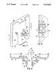
- FIG. 1is a partially exploded perspective view of an exit sign embodying the present invention
- FIG. 2is an exploded side elevational view of the exit sign and its associated electrical box with a portion of one of the housing members broken away to illustrate internal structure;
- FIG. 3is a partial top elevational view of the exit sign housing showing the opening in the housing frame sized to accept the hub assembly of the canopy bracket or a flush mounted hole plug;
- FIG. 4is a cross-sectional view taken along the 4--4 line of FIG. 3;
- FIG. 5is a top elevational view of the universal mounting plate
- FIG. 6is a partial side elevational view in partial cross section showing the assembled exit sign mounting device
- FIG. 7is a perspective view of the canopy bracket of the present invention.
- FIG. 8is a cross-sectional view taken along the 8--8 line of FIG. 7;
- FIG. 9is a side elevational view of a portion of the housing with a portion broken away to illustrate the placement of the flush mounted hole plug.
- the exit sign 10has an exit sign housing generally indicated by the numeral 12 shown with a flush mounted hole plug 14 mountable to the side thereof in elongated opening 16A, a canopy bracket 18 mounted to the top of the exit sign housing 12, and a universal mounting plate 20 mountable to both the canopy bracket 18 and a standard electrical junction box in a manner explained further hereinafter.
- the exit sign construction of this inventioncan be mounted directly to a standard electrical junction box found in a ceiling of a building in any desired location.
- the exit sign housing 12comprises a central rectangularly shaped frame 22 with front and back cover members 24 and 26, at least one of which incorporates a large stencil 28 having the letters "EXIT" in the major surface thereof and a colored plastic diffuser 29 therebehind.
- the central rectangularly shaped frame 22 and the front and back cover members 24 and 26are snap-fit together and cooperate to form an enclosure 30 (FIG. 2) for the necessary electrical lighting components such as low voltage lamps 32 and lamp sockets 34 (one of each shown in FIG. 2) as well as appropriate wiring, transformers and auxiliary power supplies (all not shown).
- the flush mounted hole plug 14can be mounted to the top of the housing 12 within an elongated opening 16B defined in the rectangularly shaped frame 22, while the canopy bracket 18 is mounted to the side of the central rectangularly shaped frame 22 within the elongated opening 16A.
- the exit sign construction of this inventioncan be mounted directly to an electrical junction box 36 located in a side wall 38 of a building in any desired location.
- the exit sign unit of the present inventioncan be adapted for flush mounting on a side wall directly to the electrical junction box 36.
- the back cover member 26can be attached directly to the electrical junction box 36 by appropriate fasteners such as screws (not shown) and appropriate wires can be threaded through the back cover member 26.
- a pair of the flush mounted hole plugs 14can then be inserted in the elongated openings 16A and 16B.
- the mounting plate 20typically known as a universal mounting plate, is provided with a pattern of apertures adapting it to be mounted to virtually every type of electrical junction box, whether square or cutoff corner. These apertures also provide threaded receptacles for retention of a pair of screws 40 captured in the canopy bracket 18.
- the mounting plate 20has a central circular opening 42 having a diameter of 1.5 inches (3.8 cm) and can be attached to the electrical junction box 36 by means of screw fasteners 43 as shown in FIG. 6.
- the canopy bracket 18 shown in FIGS. 1, 7 and 8it has a central landing portion 44 and two lower profile extending wing portions 46 surrounded by an outer flange 48 running around the periphery thereof and designed to fit flush against the associated ceiling or wall.
- the wing portions 46include threaded screw housings 50 in which the screws 40 are threadingly located.
- the canopy mounting device 52Located on the central land portion 44 of the canopy bracket 18 is a canopy mounting device generally indicated by numeral 52 for temporarily fastening the canopy bracket 18 to the mounting plate 20.
- the canopy mounting device 52includes a circular retaining wall 54 having six supporting ribs 56 extending outwardly therefrom and a pair of cantilevered resilient spring fingers 58 extending upwardly therefrom.
- the resilient spring fingers 58are dimensionally sized and placed so as to resiliently interfit in the central circular opening 42 of the mounting plate 20.
- the resilient spring fingers 58have tab end portions 60 which provide both a biasing action to them as they are inserted in the central circular opening 42 and a snap-fit engagement of the resilient spring fingers 58 within the central circular opening 42 once inserted.
- the canopy bracket 18is thus temporarily held in assembly with the mounting plate 20.
- the canopy bracket 18is turned or rotated so as to align the pair of captured screws 40 with appropriate holes in the mounting plate 20.
- the pair of captured screws 40are used to then permanently secure the canopy bracket 18 is to the mounting plate 20. It should be noted that the user, prior to final installation of the canopy bracket 18 to the mounting plate 20, will pull the electrical wires 61 from the electrical junction box 36 through the central circular opening 42 and through a central orifice 64 of the canopy.
- the canopy bracket 18incorporates a protruding hub assembly 62 which defines the central orifice 64 for the passage of electrical wires 61.
- the hub assembly 62is dimensionally sized to interfit with the elongated openings 16A and 16B and has a pair of opposed resilient spring barb members 66.
- Each resilient spring barb members 66is designed for snap-fit interconnection with a locking barb receptacle opening 68 (note FIGS. 3 and 4) found on opposite sides of both the elongated openings 16A and 16B.
- the outside surface of the resilient spring barb members 66has a pair of opposed rib members 70 dimensionally sized to interfit with mating grooves 72 found within the elongated openings 16A and 16B, thereby providing an anti-rotation keying device to prevent rotation between the canopy bracket 18 and the exit sign housing 12.
- the central landing portion 44 of the canopy bracket 18includes abutment edges 74 at either end thereof dimensionally sized to engage the central rectangularly shaped frame 22 to place a loading force on the interconnection between the resilient spring barb members 66 the hub of assembly 62 and the locking barb receptacle openings 68 of the elongated openings 16A or 16B to take up play caused by any dimensional irregularities therebetween. Accordingly, the canopy bracket 18 is fixedly secured to the central rectangularly shaped frame 22.
- the usersimply inserts the hub assembly 62 in either elongated opening 16A or 16B depending on the desired type of mounting (wall or ceiling) thereby securing the exit sign housing 12 to the wall or ceiling when the resilient spring barb members 66 cooperate with the locking barb receptacle openings 68.
- the electrical wires 61 from the electrical junction box 36pass through orifice 64 in the canopy bracket 18 and the chosen elongated opening 16A or 16B. These wires 61 would then be attached to appropriate electrical wiring (not shown) within the exit sign housing 12 to power the exit sign 10.
- the details of the flush mounted hole plug 14can be observed.
- the remaining elongated opening 16A or 16Bcan be closed by utilizing the flush mounted hole plug 14.
- the resilient hook members 76 on the flush mounted hole plug 14are aligned with and force fit within the mating grooves 72 of the chosen elongated bayonet openings 16A or 16B to hold the flush mounted hole plug 14 snugly therein. If the areas of weakness 39 on the back cover member 26 (FIG. 2) are used to flush mount the exit sign on a wall, then both elongated openings 16A and 16B can be filled with a flush mounted hole plug 14.
- the mounting plate 20is preferably stamped from corrosion-resistant sheet metal alloy material such as galvanized steel.
- the canopy bracket 18, exit sign housing 12 and the hole plug 14are preferably molded from a plastic resin such as an engineering type thermoplastic like ABS, polycarbonate or polyphenylene oxide but it should be apparent to those skilled in the art that they may be manufactured from other suitable materials which exhibit the desired resiliency to permit the desired flexing movement of the various elements.
- the present inventionprovides an effective means for facilitating installation of an exit sign to a standard electrical junction box found in a wall or ceiling. It should be appreciated that the mounting device described herein can be used to connect electrical fixtures other than exit signs to electrical junction boxes.
Landscapes
- Physics & Mathematics (AREA)
- General Physics & Mathematics (AREA)
- Engineering & Computer Science (AREA)
- Theoretical Computer Science (AREA)
- Business, Economics & Management (AREA)
- Emergency Management (AREA)
- Connection Or Junction Boxes (AREA)
- Connector Housings Or Holding Contact Members (AREA)
Abstract
Description
Claims (43)
Priority Applications (3)
| Application Number | Priority Date | Filing Date | Title |
|---|---|---|---|
| US07/925,313US5272605A (en) | 1990-09-20 | 1992-07-27 | Canopy mounting device for exit signs and the like |
| US08/169,339US5461550A (en) | 1990-09-20 | 1993-12-17 | Canopy mounting device for exit signs and the like |
| US08/525,387US5727867A (en) | 1990-09-20 | 1995-09-08 | Canopy mounting device for exit signs and the like |
Applications Claiming Priority (2)
| Application Number | Priority Date | Filing Date | Title |
|---|---|---|---|
| US58561090A | 1990-09-20 | 1990-09-20 | |
| US07/925,313US5272605A (en) | 1990-09-20 | 1992-07-27 | Canopy mounting device for exit signs and the like |
Related Parent Applications (1)
| Application Number | Title | Priority Date | Filing Date |
|---|---|---|---|
| US58561090AContinuation | 1990-09-20 | 1990-09-20 |
Related Child Applications (1)
| Application Number | Title | Priority Date | Filing Date |
|---|---|---|---|
| US08/169,339ContinuationUS5461550A (en) | 1990-09-20 | 1993-12-17 | Canopy mounting device for exit signs and the like |
Publications (1)
| Publication Number | Publication Date |
|---|---|
| US5272605Atrue US5272605A (en) | 1993-12-21 |
Family
ID=27079447
Family Applications (3)
| Application Number | Title | Priority Date | Filing Date |
|---|---|---|---|
| US07/925,313Expired - LifetimeUS5272605A (en) | 1990-09-20 | 1992-07-27 | Canopy mounting device for exit signs and the like |
| US08/169,339Expired - Fee RelatedUS5461550A (en) | 1990-09-20 | 1993-12-17 | Canopy mounting device for exit signs and the like |
| US08/525,387Expired - LifetimeUS5727867A (en) | 1990-09-20 | 1995-09-08 | Canopy mounting device for exit signs and the like |
Family Applications After (2)
| Application Number | Title | Priority Date | Filing Date |
|---|---|---|---|
| US08/169,339Expired - Fee RelatedUS5461550A (en) | 1990-09-20 | 1993-12-17 | Canopy mounting device for exit signs and the like |
| US08/525,387Expired - LifetimeUS5727867A (en) | 1990-09-20 | 1995-09-08 | Canopy mounting device for exit signs and the like |
Country Status (1)
| Country | Link |
|---|---|
| US (3) | US5272605A (en) |
Cited By (47)
| Publication number | Priority date | Publication date | Assignee | Title |
|---|---|---|---|---|
| US5461550A (en)* | 1990-09-20 | 1995-10-24 | Dual-Lite Manufacturing, Inc. | Canopy mounting device for exit signs and the like |
| US5526251A (en)* | 1994-11-22 | 1996-06-11 | National Service Industries, Inc. | Emergency lighting connections |
| US5611163A (en)* | 1994-10-21 | 1997-03-18 | National Service Industries, Inc. | Direction indicator covers for emergency lighting systems |
| US5684467A (en)* | 1995-09-07 | 1997-11-04 | Wheelock Inc. | Universal mounting plate for audible-visual alarms |
| US5735498A (en)* | 1996-05-07 | 1998-04-07 | Cooper Industries, Inc. | Apparatus for mounting an emergency sign to a support |
| USD402316S (en) | 1996-10-31 | 1998-12-08 | Gseg Llc | Sign having a curved face |
| USD405207S (en)* | 1998-06-03 | 1999-02-02 | Spaulding Lighting, Inc. | Canopy luminaire assembly |
| USD406279S (en)* | 1997-07-03 | 1999-03-02 | General Signal Corporation | Combination emergency lighting device and exit sign |
| USD406863S (en)* | 1996-10-31 | 1999-03-16 | Gseg Llc | Panel for an exit sign having a curved face |
| US5897194A (en)* | 1996-05-14 | 1999-04-27 | Ham; Byung Il | Sign with remote power source tester |
| US6082031A (en)* | 1998-07-29 | 2000-07-04 | Dual-Lite Inc. | Canopy mounting device for exit sign |
| US6095670A (en)* | 1998-07-30 | 2000-08-01 | Hubbell Incorporated | Circular mounting plate adapter for attaching an exit sign to a junction box |
| US6116749A (en)* | 1998-06-03 | 2000-09-12 | Spaulding Lighting, Inc. | Canopy luminaire assembly |
| US6132070A (en)* | 1998-07-30 | 2000-10-17 | Hubbell Incorporated | Self-aligning canopy structure for connection to a mounting plate adapter utilized for attaching an exit sign to a junction box |
| US6135624A (en)* | 1999-04-23 | 2000-10-24 | Nsi Enterprises, Inc. | Universal mounting plate for luminaire Fixture |
| US6142648A (en)* | 1995-11-22 | 2000-11-07 | Nsi Enterprises, Inc. | Emergency lighting unit/exit sign combination |
| US6149280A (en) | 1999-02-05 | 2000-11-21 | Spaulding Lighting, Inc. | Method and apparatus for retrofitting canopy luminaire assemblies |
| US6241369B1 (en) | 1998-11-20 | 2001-06-05 | Cooper Technologies Company | Quick mount fixture |
| US6271763B1 (en)* | 1995-09-07 | 2001-08-07 | Wheelock, Inc. | Audible and audible-visible alarms with interchangeable cover |
| US6499866B1 (en) | 1998-08-12 | 2002-12-31 | Acuity Brands, Inc. | Emergency lighting unit/exit sign combination |
| WO2003027570A1 (en)* | 2001-09-26 | 2003-04-03 | Ivalo Lighting Inc. | Lighting fixture mounting apparatus |
| US6595476B1 (en) | 2001-07-20 | 2003-07-22 | Donald B. Edwards | Acoustic ceiling box support |
| US7105744B1 (en) | 2003-03-18 | 2006-09-12 | Regal King Comercial Offshore De Macau Limitada | Mounting bracket for electrical fixtures |
| US20070236941A1 (en)* | 2006-02-14 | 2007-10-11 | Mark Logan | Illuminated sign insert |
| US20070277411A1 (en)* | 2006-02-14 | 2007-12-06 | Mark Logan | Illuminated sign mounting structure |
| US7350327B1 (en)* | 2004-01-22 | 2008-04-01 | Abl Ip Holding, Llc | Mounting devices for exit signs and other fixtures |
| US20080230668A1 (en)* | 2007-03-19 | 2008-09-25 | Hubbell Incorporated | Electrical fixture mounting assembly |
| US7456357B1 (en) | 2002-03-27 | 2008-11-25 | Gardenia Industrial Limited | Mounting bracket for electrical fixtures |
| USD599054S1 (en)* | 2007-07-30 | 2009-08-25 | Vode Lighting, Inc. | Canopy for light fixture |
| US20090225535A1 (en)* | 2008-03-07 | 2009-09-10 | Thomas & Betts International, Inc. | Quick install canopy |
| US20100276267A1 (en)* | 2009-05-01 | 2010-11-04 | King Enterprises | Switch assembly |
| US20110023339A1 (en)* | 2009-08-03 | 2011-02-03 | Thomas & Betts International, Inc. | Plastic canopy lock |
| US8174351B2 (en)* | 2007-05-16 | 2012-05-08 | Group Dekko, Inc. | Thermal assembly coupled with an appliance |
| US20130176743A1 (en)* | 2012-01-11 | 2013-07-11 | Sylvan R. Shemitz Designs Incorporated | Luminaire mounting interface |
| US20140247603A1 (en)* | 2010-08-27 | 2014-09-04 | Tall Tower Llc | Vandal resistant light fixture |
| FR3020709A1 (en)* | 2014-05-05 | 2015-11-06 | Cooper Technologies Co | FIXING ARRANGEMENT FOR A SIGNALING ELEMENT DISPLAY DEVICE |
| EP2801756A3 (en)* | 2013-01-11 | 2016-03-30 | Sylvan R. Shemitz Designs, Inc. | Luminaire mounting interface |
| ITUB20152072A1 (en)* | 2015-07-10 | 2017-01-10 | Beghelli Spa | FIXING SYSTEM FOR EMERGENCY LIGHTING APPLIANCES |
| US20180299105A1 (en)* | 2017-04-18 | 2018-10-18 | Dongguan Thailight Semiconductor Lighting Co., Ltd | Wall lamp mounting plate and wall lamp mounting assembly |
| FR3082045A1 (en)* | 2018-06-05 | 2019-12-06 | Signall | TEACHES |
| US10634322B1 (en)* | 2019-07-03 | 2020-04-28 | Dong Guan Jia Sheng Lighting Technology Co., Ltd. China | Quickly assembled ceiling light fixture |
| US20200363096A1 (en)* | 2019-05-14 | 2020-11-19 | Inovate Acquisition Company | Exhaust vent doors |
| USD927963S1 (en) | 2019-11-20 | 2021-08-17 | Hubbell Incorporated | Adjustable fixture mounting assembly |
| FR3109982A1 (en)* | 2020-05-06 | 2021-11-12 | Vincent Jules | Device for fixing a luminaire base that does not require the removal of the eye hook. |
| US11195438B2 (en)* | 2016-07-22 | 2021-12-07 | Thomas W. Gow | Light fixture sign |
| US11221024B2 (en) | 2019-04-10 | 2022-01-11 | Hubbell Incorporated | Ceiling fan brace assembly |
| US11536029B2 (en) | 2019-11-20 | 2022-12-27 | Hubbell Incorporated | Adjustable electrical fixture mounting assembly |
Families Citing this family (10)
| Publication number | Priority date | Publication date | Assignee | Title |
|---|---|---|---|---|
| US5964051A (en)* | 1997-03-03 | 1999-10-12 | Autronics Plastics, Inc. | Internally illuminated sign |
| US6299001B1 (en)* | 1999-09-08 | 2001-10-09 | Midwest Air Technologies, Inc. | Wall organizer system |
| US6595664B2 (en)* | 2001-02-23 | 2003-07-22 | King Of Fans, Inc. | Quick-install, flush-mount bracket for light and other fixtures |
| US20030192216A1 (en)* | 2002-04-12 | 2003-10-16 | Hsu Ju Sheng | Escape guiding or indicating device |
| US20060056170A1 (en)* | 2004-09-14 | 2006-03-16 | Thomas & Betts International, Inc. | Sign-type lighting fixture assembly |
| USD561264S1 (en) | 2006-10-17 | 2008-02-05 | Astralite, Inc. | Illuminated sign |
| USD611547S1 (en)* | 2008-05-20 | 2010-03-09 | Thomas & Betts International, Inc. | Exit sign |
| USD597434S1 (en) | 2008-10-17 | 2009-08-04 | Astralite, Inc. | Emergency light |
| US20110043041A1 (en)* | 2009-08-18 | 2011-02-24 | Kevin Porter | Sinusoidal Alternating Current Ballast For Fluorescent Emergency Lighting |
| US8388170B2 (en)* | 2009-12-08 | 2013-03-05 | Cooper Technologies Company | External mechanical battery disconnect for emergency lighting products |
Citations (16)
| Publication number | Priority date | Publication date | Assignee | Title |
|---|---|---|---|---|
| US1646807A (en)* | 1921-08-22 | 1927-10-25 | Benjamin Electric Mfg Co | Fixture connecter |
| US1933358A (en)* | 1929-04-15 | 1933-10-31 | Edward L Kappelman | Outlet box |
| US3086308A (en)* | 1959-06-29 | 1963-04-23 | Westlake G Ternouth | Shelf-edge sign |
| US3798584A (en)* | 1972-05-22 | 1974-03-19 | J Person | Quick connect ceiling electrical fixture mounting |
| US3886349A (en)* | 1971-08-05 | 1975-05-27 | Akira Arai | Mechanical connecting device |
| US3931689A (en)* | 1974-06-12 | 1976-01-13 | Dual-Lite Company | Illuminated sign housing construction |
| US4273957A (en)* | 1979-06-06 | 1981-06-16 | Kolling Jr William J | Telecommunications access apparatus |
| US4426126A (en)* | 1981-11-02 | 1984-01-17 | Gte Products Corporation | Lighting fixture connecting device with safety means |
| US4449168A (en)* | 1981-10-16 | 1984-05-15 | Manville Service Corporation | Quick install device for mounting a luminaire |
| US4507719A (en)* | 1983-11-17 | 1985-03-26 | Harvey Hubbell Incorporated | Heat dissipator for plastic luminaire |
| US4532579A (en)* | 1984-04-13 | 1985-07-30 | Bill Merryman | Illuminated interconnectable sign module |
| US4561203A (en)* | 1983-08-04 | 1985-12-31 | Dual-Lite Manufacturing | Opaque sign plaque with dual reflector illumination |
| US4820956A (en)* | 1987-10-02 | 1989-04-11 | Integrated Systems Engineering, Inc. | Light matrix display system |
| US5018290A (en)* | 1989-02-23 | 1991-05-28 | Dual-Lite, Inc. | Exit sign |
| US5022627A (en)* | 1988-12-20 | 1991-06-11 | G.P.B. Geghelli S.R.L. | Sign projecting from vertical walls or horizontal beams |
| US5142454A (en)* | 1991-11-18 | 1992-08-25 | Ford Motor Company | Vehicle lamp assembly |
Family Cites Families (2)
| Publication number | Priority date | Publication date | Assignee | Title |
|---|---|---|---|---|
| US1933338A (en)* | 1931-10-21 | 1933-10-31 | Westinghouse Lamp Co | Combined lamp container and reflector |
| US5272605A (en)* | 1990-09-20 | 1993-12-21 | Dual-Lite Manufacturing, Inc. | Canopy mounting device for exit signs and the like |
- 1992
- 1992-07-27USUS07/925,313patent/US5272605A/ennot_activeExpired - Lifetime
- 1993
- 1993-12-17USUS08/169,339patent/US5461550A/ennot_activeExpired - Fee Related
- 1995
- 1995-09-08USUS08/525,387patent/US5727867A/ennot_activeExpired - Lifetime
Patent Citations (16)
| Publication number | Priority date | Publication date | Assignee | Title |
|---|---|---|---|---|
| US1646807A (en)* | 1921-08-22 | 1927-10-25 | Benjamin Electric Mfg Co | Fixture connecter |
| US1933358A (en)* | 1929-04-15 | 1933-10-31 | Edward L Kappelman | Outlet box |
| US3086308A (en)* | 1959-06-29 | 1963-04-23 | Westlake G Ternouth | Shelf-edge sign |
| US3886349A (en)* | 1971-08-05 | 1975-05-27 | Akira Arai | Mechanical connecting device |
| US3798584A (en)* | 1972-05-22 | 1974-03-19 | J Person | Quick connect ceiling electrical fixture mounting |
| US3931689A (en)* | 1974-06-12 | 1976-01-13 | Dual-Lite Company | Illuminated sign housing construction |
| US4273957A (en)* | 1979-06-06 | 1981-06-16 | Kolling Jr William J | Telecommunications access apparatus |
| US4449168A (en)* | 1981-10-16 | 1984-05-15 | Manville Service Corporation | Quick install device for mounting a luminaire |
| US4426126A (en)* | 1981-11-02 | 1984-01-17 | Gte Products Corporation | Lighting fixture connecting device with safety means |
| US4561203A (en)* | 1983-08-04 | 1985-12-31 | Dual-Lite Manufacturing | Opaque sign plaque with dual reflector illumination |
| US4507719A (en)* | 1983-11-17 | 1985-03-26 | Harvey Hubbell Incorporated | Heat dissipator for plastic luminaire |
| US4532579A (en)* | 1984-04-13 | 1985-07-30 | Bill Merryman | Illuminated interconnectable sign module |
| US4820956A (en)* | 1987-10-02 | 1989-04-11 | Integrated Systems Engineering, Inc. | Light matrix display system |
| US5022627A (en)* | 1988-12-20 | 1991-06-11 | G.P.B. Geghelli S.R.L. | Sign projecting from vertical walls or horizontal beams |
| US5018290A (en)* | 1989-02-23 | 1991-05-28 | Dual-Lite, Inc. | Exit sign |
| US5142454A (en)* | 1991-11-18 | 1992-08-25 | Ford Motor Company | Vehicle lamp assembly |
Non-Patent Citations (5)
| Title |
|---|
| Drawing No. 1300323.* |
| Excite canopy with nipple and two nuts.* |
| Excite frame.* |
| Excite Installation Manual No. 60 972B.* |
| Excite Installation Manual No. 60-972B. |
Cited By (66)
| Publication number | Priority date | Publication date | Assignee | Title |
|---|---|---|---|---|
| US5727867A (en)* | 1990-09-20 | 1998-03-17 | Gseg Llc | Canopy mounting device for exit signs and the like |
| US5461550A (en)* | 1990-09-20 | 1995-10-24 | Dual-Lite Manufacturing, Inc. | Canopy mounting device for exit signs and the like |
| US5611163A (en)* | 1994-10-21 | 1997-03-18 | National Service Industries, Inc. | Direction indicator covers for emergency lighting systems |
| US5526251A (en)* | 1994-11-22 | 1996-06-11 | National Service Industries, Inc. | Emergency lighting connections |
| US5684467A (en)* | 1995-09-07 | 1997-11-04 | Wheelock Inc. | Universal mounting plate for audible-visual alarms |
| US5805071A (en)* | 1995-09-07 | 1998-09-08 | Wheelock, Inc. | Universal mounting plate for audible-visual alarms |
| US6271763B1 (en)* | 1995-09-07 | 2001-08-07 | Wheelock, Inc. | Audible and audible-visible alarms with interchangeable cover |
| US6142648A (en)* | 1995-11-22 | 2000-11-07 | Nsi Enterprises, Inc. | Emergency lighting unit/exit sign combination |
| US5735498A (en)* | 1996-05-07 | 1998-04-07 | Cooper Industries, Inc. | Apparatus for mounting an emergency sign to a support |
| US5897194A (en)* | 1996-05-14 | 1999-04-27 | Ham; Byung Il | Sign with remote power source tester |
| USD406863S (en)* | 1996-10-31 | 1999-03-16 | Gseg Llc | Panel for an exit sign having a curved face |
| USD402316S (en) | 1996-10-31 | 1998-12-08 | Gseg Llc | Sign having a curved face |
| USD406279S (en)* | 1997-07-03 | 1999-03-02 | General Signal Corporation | Combination emergency lighting device and exit sign |
| US6116749A (en)* | 1998-06-03 | 2000-09-12 | Spaulding Lighting, Inc. | Canopy luminaire assembly |
| USD405207S (en)* | 1998-06-03 | 1999-02-02 | Spaulding Lighting, Inc. | Canopy luminaire assembly |
| US6264344B1 (en) | 1998-06-03 | 2001-07-24 | Spaulding Lighting, Inc. | Canopy luminaire assembly |
| US6367945B2 (en) | 1998-06-03 | 2002-04-09 | Spalding Lighting, Inc. | Canopy luminaire assembly |
| US6082031A (en)* | 1998-07-29 | 2000-07-04 | Dual-Lite Inc. | Canopy mounting device for exit sign |
| US6095670A (en)* | 1998-07-30 | 2000-08-01 | Hubbell Incorporated | Circular mounting plate adapter for attaching an exit sign to a junction box |
| US6132070A (en)* | 1998-07-30 | 2000-10-17 | Hubbell Incorporated | Self-aligning canopy structure for connection to a mounting plate adapter utilized for attaching an exit sign to a junction box |
| US6499866B1 (en) | 1998-08-12 | 2002-12-31 | Acuity Brands, Inc. | Emergency lighting unit/exit sign combination |
| US6241369B1 (en) | 1998-11-20 | 2001-06-05 | Cooper Technologies Company | Quick mount fixture |
| US6149280A (en) | 1999-02-05 | 2000-11-21 | Spaulding Lighting, Inc. | Method and apparatus for retrofitting canopy luminaire assemblies |
| US6135624A (en)* | 1999-04-23 | 2000-10-24 | Nsi Enterprises, Inc. | Universal mounting plate for luminaire Fixture |
| US6595476B1 (en) | 2001-07-20 | 2003-07-22 | Donald B. Edwards | Acoustic ceiling box support |
| WO2003027570A1 (en)* | 2001-09-26 | 2003-04-03 | Ivalo Lighting Inc. | Lighting fixture mounting apparatus |
| US20030082948A1 (en)* | 2001-09-26 | 2003-05-01 | Ivalo Lighting Inc. | Lighting fixture mounting apparatus |
| US7456357B1 (en) | 2002-03-27 | 2008-11-25 | Gardenia Industrial Limited | Mounting bracket for electrical fixtures |
| US7105744B1 (en) | 2003-03-18 | 2006-09-12 | Regal King Comercial Offshore De Macau Limitada | Mounting bracket for electrical fixtures |
| US7786379B1 (en) | 2003-03-18 | 2010-08-31 | Gardenia Industrial Limited | Method for attaching an electrical fixture to a junction box |
| US7350327B1 (en)* | 2004-01-22 | 2008-04-01 | Abl Ip Holding, Llc | Mounting devices for exit signs and other fixtures |
| US20070236941A1 (en)* | 2006-02-14 | 2007-10-11 | Mark Logan | Illuminated sign insert |
| US20070277411A1 (en)* | 2006-02-14 | 2007-12-06 | Mark Logan | Illuminated sign mounting structure |
| US7739818B2 (en)* | 2006-02-14 | 2010-06-22 | ABL IP Lighting, LLC | Illuminated sign insert |
| US7845103B2 (en)* | 2006-02-14 | 2010-12-07 | Acuity Brands, Inc. | Illuminated sign mounting structure |
| US20080230668A1 (en)* | 2007-03-19 | 2008-09-25 | Hubbell Incorporated | Electrical fixture mounting assembly |
| US7837172B2 (en)* | 2007-03-19 | 2010-11-23 | Hubbell Incorporated | Electrical fixture mounting assembly |
| US8174351B2 (en)* | 2007-05-16 | 2012-05-08 | Group Dekko, Inc. | Thermal assembly coupled with an appliance |
| USD599054S1 (en)* | 2007-07-30 | 2009-08-25 | Vode Lighting, Inc. | Canopy for light fixture |
| US20090225535A1 (en)* | 2008-03-07 | 2009-09-10 | Thomas & Betts International, Inc. | Quick install canopy |
| US7753552B2 (en) | 2008-03-07 | 2010-07-13 | Thomas & Betts International, Inc. | Quick install canopy |
| US20100276267A1 (en)* | 2009-05-01 | 2010-11-04 | King Enterprises | Switch assembly |
| US8203090B2 (en)* | 2009-05-01 | 2012-06-19 | King Enterprises | Switch assembly |
| US20110023339A1 (en)* | 2009-08-03 | 2011-02-03 | Thomas & Betts International, Inc. | Plastic canopy lock |
| US8348447B2 (en) | 2009-08-03 | 2013-01-08 | Thomas & Betts International, Inc. | Plastic canopy lock |
| US20140247603A1 (en)* | 2010-08-27 | 2014-09-04 | Tall Tower Llc | Vandal resistant light fixture |
| US9612003B2 (en)* | 2010-08-27 | 2017-04-04 | Tall Tower Led, Llc | Vandal resistant light fixture |
| US20130176743A1 (en)* | 2012-01-11 | 2013-07-11 | Sylvan R. Shemitz Designs Incorporated | Luminaire mounting interface |
| USD777370S1 (en) | 2012-01-11 | 2017-01-24 | Sylvan R. Shemitz Designs, Llc | Luminaire mounting interface |
| USD747030S1 (en) | 2012-01-11 | 2016-01-05 | Sylvan R. Shemitz Designs, Llc | Luminaire mounting interface |
| EP2801756A3 (en)* | 2013-01-11 | 2016-03-30 | Sylvan R. Shemitz Designs, Inc. | Luminaire mounting interface |
| EP2942770A1 (en)* | 2014-05-05 | 2015-11-11 | Cooper Technologies Company | Arrangement for securing a device for displaying a signalling element |
| FR3020709A1 (en)* | 2014-05-05 | 2015-11-06 | Cooper Technologies Co | FIXING ARRANGEMENT FOR A SIGNALING ELEMENT DISPLAY DEVICE |
| ITUB20152072A1 (en)* | 2015-07-10 | 2017-01-10 | Beghelli Spa | FIXING SYSTEM FOR EMERGENCY LIGHTING APPLIANCES |
| US11195438B2 (en)* | 2016-07-22 | 2021-12-07 | Thomas W. Gow | Light fixture sign |
| US20180299105A1 (en)* | 2017-04-18 | 2018-10-18 | Dongguan Thailight Semiconductor Lighting Co., Ltd | Wall lamp mounting plate and wall lamp mounting assembly |
| FR3082045A1 (en)* | 2018-06-05 | 2019-12-06 | Signall | TEACHES |
| US11221024B2 (en) | 2019-04-10 | 2022-01-11 | Hubbell Incorporated | Ceiling fan brace assembly |
| US20200363096A1 (en)* | 2019-05-14 | 2020-11-19 | Inovate Acquisition Company | Exhaust vent doors |
| US12385656B2 (en)* | 2019-05-14 | 2025-08-12 | Inovate Acquisition Company | Exhaust vent doors |
| US10634322B1 (en)* | 2019-07-03 | 2020-04-28 | Dong Guan Jia Sheng Lighting Technology Co., Ltd. China | Quickly assembled ceiling light fixture |
| USD927963S1 (en) | 2019-11-20 | 2021-08-17 | Hubbell Incorporated | Adjustable fixture mounting assembly |
| USD964944S1 (en) | 2019-11-20 | 2022-09-27 | Hubbell Incorporated | Adjustable fixture mounting assembly |
| US11536029B2 (en) | 2019-11-20 | 2022-12-27 | Hubbell Incorporated | Adjustable electrical fixture mounting assembly |
| US12163333B2 (en) | 2019-11-20 | 2024-12-10 | Hubbell Incorporated | Adjustable electrical fixture mounting assembly |
| FR3109982A1 (en)* | 2020-05-06 | 2021-11-12 | Vincent Jules | Device for fixing a luminaire base that does not require the removal of the eye hook. |
Also Published As
| Publication number | Publication date |
|---|---|
| US5461550A (en) | 1995-10-24 |
| US5727867A (en) | 1998-03-17 |
Similar Documents
| Publication | Publication Date | Title |
|---|---|---|
| US5272605A (en) | Canopy mounting device for exit signs and the like | |
| US5768814A (en) | Exit sign with removable emergency power pack module | |
| US6132070A (en) | Self-aligning canopy structure for connection to a mounting plate adapter utilized for attaching an exit sign to a junction box | |
| US7036961B2 (en) | Recessed lighting fixture with battery backup | |
| US7350327B1 (en) | Mounting devices for exit signs and other fixtures | |
| US6530681B2 (en) | Surface-mounted decorative trim ceiling fixture | |
| CA2163512C (en) | Emergency lighting connections | |
| US8021007B2 (en) | Concealed emergency lighting equipment with complete retrofit housing and method of installation | |
| US11710952B2 (en) | Weatherproof electrical enclosure with reinforcement | |
| US20040238197A1 (en) | Electrical box with recessed faceplate | |
| GB2181906A (en) | Emergency lighting units | |
| US7845103B2 (en) | Illuminated sign mounting structure | |
| US6050013A (en) | Mounting device for exit sign covers | |
| US6082031A (en) | Canopy mounting device for exit sign | |
| US7739818B2 (en) | Illuminated sign insert | |
| US7866843B2 (en) | Corner mounted light fixture | |
| US6825414B2 (en) | Exterior mounting block for electrical fixtures | |
| EA012758B1 (en) | Support frame and a group of parts, including such frame wall mounting an electrical apparatus | |
| US6152413A (en) | Mounting block | |
| US5942727A (en) | Universal mounting plate for lamp ballasts | |
| CA2656394C (en) | Quick install canopy | |
| CA2047924C (en) | Canopy mounting device for exit signs and the like | |
| US5735498A (en) | Apparatus for mounting an emergency sign to a support | |
| US6095670A (en) | Circular mounting plate adapter for attaching an exit sign to a junction box | |
| US20060056170A1 (en) | Sign-type lighting fixture assembly |
Legal Events
| Date | Code | Title | Description |
|---|---|---|---|
| STCF | Information on status: patent grant | Free format text:PATENTED CASE | |
| CC | Certificate of correction | ||
| FEPP | Fee payment procedure | Free format text:PAYOR NUMBER ASSIGNED (ORIGINAL EVENT CODE: ASPN); ENTITY STATUS OF PATENT OWNER: LARGE ENTITY | |
| FPAY | Fee payment | Year of fee payment:4 | |
| AS | Assignment | Owner name:WILMINGTON TRUST COMPANY, DELAWARE Free format text:SECURITY AGREEMENT;ASSIGNORS:AMES TRUE TEMPER PROPERTIES, INC;AMES TRUE TEMPER, INC;ARCHITECTURAL AREA LIGHTING, INC.;AND OTHERS;REEL/FRAME:011731/0097 Effective date:20010430 | |
| FPAY | Fee payment | Year of fee payment:8 | |
| AS | Assignment | Owner name:ENVIRONMENTAL ENERGY COMPANY, FLORIDA Free format text:RELEASE OF SECURITY INTEREST IN INTELLECTUAL PROPERTY;ASSIGNOR:WILMINGTON TRUST COMPANY AS CORPORATE TRUSTEE;REEL/FRAME:015134/0225 Effective date:20030715 Owner name:LIGHTING CORPORATION OF AMERICA, INC., FLORIDA Free format text:RELEASE OF SECURITY INTEREST IN INTELLECTUAL PROPERTY;ASSIGNOR:WILMINGTON TRUST COMPANY AS CORPORATE TRUSTEE;REEL/FRAME:015134/0225 Effective date:20030715 Owner name:NEPCO OF FORD HIGHTS, INC., FLORIDA Free format text:RELEASE OF SECURITY INTEREST IN INTELLECTUAL PROPERTY;ASSIGNOR:WILMINGTON TRUST COMPANY AS CORPORATE TRUSTEE;REEL/FRAME:015134/0225 Effective date:20030715 Owner name:HL CAPITAL CORP., FLORIDA Free format text:RELEASE OF SECURITY INTEREST IN INTELLECTUAL PROPERTY;ASSIGNOR:WILMINGTON TRUST COMPANY AS CORPORATE TRUSTEE;REEL/FRAME:015134/0225 Effective date:20030715 Owner name:NEPCO OF FULTON, INC., FLORIDA Free format text:RELEASE OF SECURITY INTEREST IN INTELLECTUAL PROPERTY;ASSIGNOR:WILMINGTON TRUST COMPANY AS CORPORATE TRUSTEE;REEL/FRAME:015134/0225 Effective date:20030715 Owner name:PH PROPERTY DEVELOPMENT COMPANY, FLORIDA Free format text:RELEASE OF SECURITY INTEREST IN INTELLECTUAL PROPERTY;ASSIGNOR:WILMINGTON TRUST COMPANY AS CORPORATE TRUSTEE;REEL/FRAME:015134/0225 Effective date:20030715 Owner name:SELKIRK EUROPE U.S.A., INC., FLORIDA Free format text:RELEASE OF SECURITY INTEREST IN INTELLECTUAL PROPERTY;ASSIGNOR:WILMINGTON TRUST COMPANY AS CORPORATE TRUSTEE;REEL/FRAME:015134/0225 Effective date:20030715 Owner name:OUTDOOR PRODUCTS LLC, FLORIDA Free format text:RELEASE OF SECURITY INTEREST IN INTELLECTUAL PROPERTY;ASSIGNOR:WILMINGTON TRUST COMPANY AS CORPORATE TRUSTEE;REEL/FRAME:015134/0225 Effective date:20030715 Owner name:JUSI HOLDINGS, INC., FLORIDA Free format text:RELEASE OF SECURITY INTEREST IN INTELLECTUAL PROPERTY;ASSIGNOR:WILMINGTON TRUST COMPANY AS CORPORATE TRUSTEE;REEL/FRAME:015134/0225 Effective date:20030715 Owner name:ZURN GOLF HOLDING CORPORATION, FLORIDA Free format text:RELEASE OF SECURITY INTEREST IN INTELLECTUAL PROPERTY;ASSIGNOR:WILMINGTON TRUST COMPANY AS CORPORATE TRUSTEE;REEL/FRAME:015134/0225 Effective date:20030715 Owner name:PRESCOLITE LITE CONTROLS, INC., FLORIDA Free format text:RELEASE OF SECURITY INTEREST IN INTELLECTUAL PROPERTY;ASSIGNOR:WILMINGTON TRUST COMPANY AS CORPORATE TRUSTEE;REEL/FRAME:015134/0225 Effective date:20030715 Owner name:ELJER PLUMBINGWARE, INC., FLORIDA Free format text:RELEASE OF SECURITY INTEREST IN INTELLECTUAL PROPERTY;ASSIGNOR:WILMINGTON TRUST COMPANY AS CORPORATE TRUSTEE;REEL/FRAME:015134/0225 Effective date:20030715 Owner name:SELKIRK, INC., FLORIDA Free format text:RELEASE OF SECURITY INTEREST IN INTELLECTUAL PROPERTY;ASSIGNOR:WILMINGTON TRUST COMPANY AS CORPORATE TRUSTEE;REEL/FRAME:015134/0225 Effective date:20030715 Owner name:PRESCOLITE, INC., FLORIDA Free format text:RELEASE OF SECURITY INTEREST IN INTELLECTUAL PROPERTY;ASSIGNOR:WILMINGTON TRUST COMPANY AS CORPORATE TRUSTEE;REEL/FRAME:015134/0225 Effective date:20030715 Owner name:DUAL-LITE MANUFACTURING, INC., FLORIDA Free format text:RELEASE OF SECURITY INTEREST IN INTELLECTUAL PROPERTY;ASSIGNOR:WILMINGTON TRUST COMPANY AS CORPORATE TRUSTEE;REEL/FRAME:015134/0225 Effective date:20030715 Owner name:SPAULDING LIGHTING, INC., FLORIDA Free format text:RELEASE OF SECURITY INTEREST IN INTELLECTUAL PROPERTY;ASSIGNOR:WILMINGTON TRUST COMPANY AS CORPORATE TRUSTEE;REEL/FRAME:015134/0225 Effective date:20030715 Owner name:ZURNACQ OF CALIFORNIA, INC., FLORIDA Free format text:RELEASE OF SECURITY INTEREST IN INTELLECTUAL PROPERTY;ASSIGNOR:WILMINGTON TRUST COMPANY AS CORPORATE TRUSTEE;REEL/FRAME:015134/0225 Effective date:20030715 Owner name:AMES TRUE TEMPER PROPRETIES, INC., FLORIDA Free format text:RELEASE OF SECURITY INTEREST IN INTELLECTUAL PROPERTY;ASSIGNOR:WILMINGTON TRUST COMPANY AS CORPORATE TRUSTEE;REEL/FRAME:015134/0225 Effective date:20030715 Owner name:AMES TRUE TEMPER, INC., FLORIDA Free format text:RELEASE OF SECURITY INTEREST IN INTELLECTUAL PROPERTY;ASSIGNOR:WILMINGTON TRUST COMPANY AS CORPORATE TRUSTEE;REEL/FRAME:015134/0225 Effective date:20030715 Owner name:NEPCO OF AUSTRALIA, INC., FLORIDA Free format text:RELEASE OF SECURITY INTEREST IN INTELLECTUAL PROPERTY;ASSIGNOR:WILMINGTON TRUST COMPANY AS CORPORATE TRUSTEE;REEL/FRAME:015134/0225 Effective date:20030715 Owner name:GARY CONCRETE PRODUCTS, INC., FLORIDA Free format text:RELEASE OF SECURITY INTEREST IN INTELLECTUAL PROPERTY;ASSIGNOR:WILMINGTON TRUST COMPANY AS CORPORATE TRUSTEE;REEL/FRAME:015134/0225 Effective date:20030715 Owner name:ARCHITECTURAL AREA LIGHTING, INC., FLORIDA Free format text:RELEASE OF SECURITY INTEREST IN INTELLECTUAL PROPERTY;ASSIGNOR:WILMINGTON TRUST COMPANY AS CORPORATE TRUSTEE;REEL/FRAME:015134/0225 Effective date:20030715 Owner name:STRATEGIC CAPITAL MANAGEMENT, INC., FLORIDA Free format text:RELEASE OF SECURITY INTEREST IN INTELLECTUAL PROPERTY;ASSIGNOR:WILMINGTON TRUST COMPANY AS CORPORATE TRUSTEE;REEL/FRAME:015134/0225 Effective date:20030715 Owner name:ARROW CONSOLIDATED CORPORATION, FLORIDA Free format text:RELEASE OF SECURITY INTEREST IN INTELLECTUAL PROPERTY;ASSIGNOR:WILMINGTON TRUST COMPANY AS CORPORATE TRUSTEE;REEL/FRAME:015134/0225 Effective date:20030715 Owner name:EZ HOLDING, INC., FLORIDA Free format text:RELEASE OF SECURITY INTEREST IN INTELLECTUAL PROPERTY;ASSIGNOR:WILMINGTON TRUST COMPANY AS CORPORATE TRUSTEE;REEL/FRAME:015134/0225 Effective date:20030715 Owner name:ZURN INDUSTRIES, INC., FLORIDA Free format text:RELEASE OF SECURITY INTEREST IN INTELLECTUAL PROPERTY;ASSIGNOR:WILMINGTON TRUST COMPANY AS CORPORATE TRUSTEE;REEL/FRAME:015134/0225 Effective date:20030715 Owner name:ASTERIA COMPANY, FLORIDA Free format text:RELEASE OF SECURITY INTEREST IN INTELLECTUAL PROPERTY;ASSIGNOR:WILMINGTON TRUST COMPANY AS CORPORATE TRUSTEE;REEL/FRAME:015134/0225 Effective date:20030715 Owner name:BATHCRAFT INC., FLORIDA Free format text:RELEASE OF SECURITY INTEREST IN INTELLECTUAL PROPERTY;ASSIGNOR:WILMINGTON TRUST COMPANY AS CORPORATE TRUSTEE;REEL/FRAME:015134/0225 Effective date:20030715 Owner name:PROGRESS LIGHTING, INC., FLORIDA Free format text:RELEASE OF SECURITY INTEREST IN INTELLECTUAL PROPERTY;ASSIGNOR:WILMINGTON TRUST COMPANY AS CORPORATE TRUSTEE;REEL/FRAME:015134/0225 Effective date:20030715 Owner name:BAYLIS BROTHERS, INC., FLORIDA Free format text:RELEASE OF SECURITY INTEREST IN INTELLECTUAL PROPERTY;ASSIGNOR:WILMINGTON TRUST COMPANY AS CORPORATE TRUSTEE;REEL/FRAME:015134/0225 Effective date:20030715 Owner name:BRUCKNER MANUFACTURING COP., FLORIDA Free format text:RELEASE OF SECURITY INTEREST IN INTELLECTUAL PROPERTY;ASSIGNOR:WILMINGTON TRUST COMPANY AS CORPORATE TRUSTEE;REEL/FRAME:015134/0225 Effective date:20030715 Owner name:CARLSBAD CORP., FLORIDA Free format text:RELEASE OF SECURITY INTEREST IN INTELLECTUAL PROPERTY;ASSIGNOR:WILMINGTON TRUST COMPANY AS CORPORATE TRUSTEE;REEL/FRAME:015134/0225 Effective date:20030715 Owner name:COLUBMIA LIGHTING PROPERTIES, INC., FLORIDA Free format text:RELEASE OF SECURITY INTEREST IN INTELLECTUAL PROPERTY;ASSIGNOR:WILMINGTON TRUST COMPANY AS CORPORATE TRUSTEE;REEL/FRAME:015134/0225 Effective date:20030715 Owner name:ZURN EPC SERVICES, INC., FLORIDA Free format text:RELEASE OF SECURITY INTEREST IN INTELLECTUAL PROPERTY;ASSIGNOR:WILMINGTON TRUST COMPANY AS CORPORATE TRUSTEE;REEL/FRAME:015134/0225 Effective date:20030715 Owner name:COLUMBIA LIGHTING MFG., INC., FLORIDA Free format text:RELEASE OF SECURITY INTEREST IN INTELLECTUAL PROPERTY;ASSIGNOR:WILMINGTON TRUST COMPANY AS CORPORATE TRUSTEE;REEL/FRAME:015134/0225 Effective date:20030715 Owner name:SELKIRK CANADA U.S.A., INC., FLORIDA Free format text:RELEASE OF SECURITY INTEREST IN INTELLECTUAL PROPERTY;ASSIGNOR:WILMINGTON TRUST COMPANY AS CORPORATE TRUSTEE;REEL/FRAME:015134/0225 Effective date:20030715 Owner name:IXL MANUFACTURING COMPANY, INC., FLORIDA Free format text:RELEASE OF SECURITY INTEREST IN INTELLECTUAL PROPERTY;ASSIGNOR:WILMINGTON TRUST COMPANY AS CORPORATE TRUSTEE;REEL/FRAME:015134/0225 Effective date:20030715 Owner name:COLUMBIA LIGHTING-LCA, INC., FLORIDA Free format text:RELEASE OF SECURITY INTEREST IN INTELLECTUAL PROPERTY;ASSIGNOR:WILMINGTON TRUST COMPANY AS CORPORATE TRUSTEE;REEL/FRAME:015134/0225 Effective date:20030715 Owner name:DUAL-LITE INC., FLORIDA Free format text:RELEASE OF SECURITY INTEREST IN INTELLECTUAL PROPERTY;ASSIGNOR:WILMINGTON TRUST COMPANY AS CORPORATE TRUSTEE;REEL/FRAME:015134/0225 Effective date:20030715 Owner name:COLUMBIA LIGHTING, INC., FLORIDA Free format text:RELEASE OF SECURITY INTEREST IN INTELLECTUAL PROPERTY;ASSIGNOR:WILMINGTON TRUST COMPANY AS CORPORATE TRUSTEE;REEL/FRAME:015134/0225 Effective date:20030715 Owner name:COLUMBIA MATERIALS, LLC, FLORIDA Free format text:RELEASE OF SECURITY INTEREST IN INTELLECTUAL PROPERTY;ASSIGNOR:WILMINGTON TRUST COMPANY AS CORPORATE TRUSTEE;REEL/FRAME:015134/0225 Effective date:20030715 Owner name:ELJER INDUSTRIES, INC., FLORIDA Free format text:RELEASE OF SECURITY INTEREST IN INTELLECTUAL PROPERTY;ASSIGNOR:WILMINGTON TRUST COMPANY AS CORPORATE TRUSTEE;REEL/FRAME:015134/0225 Effective date:20030715 Owner name:USI FUNDING, INC., FLORIDA Free format text:RELEASE OF SECURITY INTEREST IN INTELLECTUAL PROPERTY;ASSIGNOR:WILMINGTON TRUST COMPANY AS CORPORATE TRUSTEE;REEL/FRAME:015134/0225 Effective date:20030715 Owner name:JACUZZI WHIRLPOOL BATH, INC., FLORIDA Free format text:RELEASE OF SECURITY INTEREST IN INTELLECTUAL PROPERTY;ASSIGNOR:WILMINGTON TRUST COMPANY AS CORPORATE TRUSTEE;REEL/FRAME:015134/0225 Effective date:20030715 Owner name:KLI, INC., FLORIDA Free format text:RELEASE OF SECURITY INTEREST IN INTELLECTUAL PROPERTY;ASSIGNOR:WILMINGTON TRUST COMPANY AS CORPORATE TRUSTEE;REEL/FRAME:015134/0225 Effective date:20030715 Owner name:STREAMWOOD CORPORATION, FLORIDA Free format text:RELEASE OF SECURITY INTEREST IN INTELLECTUAL PROPERTY;ASSIGNOR:WILMINGTON TRUST COMPANY AS CORPORATE TRUSTEE;REEL/FRAME:015134/0225 Effective date:20030715 Owner name:COMPAX CORP., FLORIDA Free format text:RELEASE OF SECURITY INTEREST IN INTELLECTUAL PROPERTY;ASSIGNOR:WILMINGTON TRUST COMPANY AS CORPORATE TRUSTEE;REEL/FRAME:015134/0225 Effective date:20030715 Owner name:ZURCO, INC., FLORIDA Free format text:RELEASE OF SECURITY INTEREST IN INTELLECTUAL PROPERTY;ASSIGNOR:WILMINGTON TRUST COMPANY AS CORPORATE TRUSTEE;REEL/FRAME:015134/0225 Effective date:20030715 Owner name:USI AMERICAN HOLDINGS, INC., FLORIDA Free format text:RELEASE OF SECURITY INTEREST IN INTELLECTUAL PROPERTY;ASSIGNOR:WILMINGTON TRUST COMPANY AS CORPORATE TRUSTEE;REEL/FRAME:015134/0225 Effective date:20030715 Owner name:LCA (NS) INC., FLORIDA Free format text:RELEASE OF SECURITY INTEREST IN INTELLECTUAL PROPERTY;ASSIGNOR:WILMINGTON TRUST COMPANY AS CORPORATE TRUSTEE;REEL/FRAME:015134/0225 Effective date:20030715 Owner name:REDMONT, INC., FLORIDA Free format text:RELEASE OF SECURITY INTEREST IN INTELLECTUAL PROPERTY;ASSIGNOR:WILMINGTON TRUST COMPANY AS CORPORATE TRUSTEE;REEL/FRAME:015134/0225 Effective date:20030715 Owner name:NISSEN UNIVERSAL HOLDINGS INC., FLORIDA Free format text:RELEASE OF SECURITY INTEREST IN INTELLECTUAL PROPERTY;ASSIGNOR:WILMINGTON TRUST COMPANY AS CORPORATE TRUSTEE;REEL/FRAME:015134/0225 Effective date:20030715 Owner name:ZURN CONSTRUCTORS, INC., FLORIDA Free format text:RELEASE OF SECURITY INTEREST IN INTELLECTUAL PROPERTY;ASSIGNOR:WILMINGTON TRUST COMPANY AS CORPORATE TRUSTEE;REEL/FRAME:015134/0225 Effective date:20030715 Owner name:GATSBY SPAS, INC., FLORIDA Free format text:RELEASE OF SECURITY INTEREST IN INTELLECTUAL PROPERTY;ASSIGNOR:WILMINGTON TRUST COMPANY AS CORPORATE TRUSTEE;REEL/FRAME:015134/0225 Effective date:20030715 Owner name:LCA GROUP INC., FLORIDA Free format text:RELEASE OF SECURITY INTEREST IN INTELLECTUAL PROPERTY;ASSIGNOR:WILMINGTON TRUST COMPANY AS CORPORATE TRUSTEE;REEL/FRAME:015134/0225 Effective date:20030715 Owner name:USI CAPITAL, INC., FLORIDA Free format text:RELEASE OF SECURITY INTEREST IN INTELLECTUAL PROPERTY;ASSIGNOR:WILMINGTON TRUST COMPANY AS CORPORATE TRUSTEE;REEL/FRAME:015134/0225 Effective date:20030715 Owner name:LUXOR INDUSRIES, INC., FLORIDA Free format text:RELEASE OF SECURITY INTEREST IN INTELLECTUAL PROPERTY;ASSIGNOR:WILMINGTON TRUST COMPANY AS CORPORATE TRUSTEE;REEL/FRAME:015134/0225 Effective date:20030715 Owner name:LOKELANI DEVELOPMENT CORPORATION, FLORIDA Free format text:RELEASE OF SECURITY INTEREST IN INTELLECTUAL PROPERTY;ASSIGNOR:WILMINGTON TRUST COMPANY AS CORPORATE TRUSTEE;REEL/FRAME:015134/0225 Effective date:20030715 Owner name:NEPCO OF CANADA, INC., FLORIDA Free format text:RELEASE OF SECURITY INTEREST IN INTELLECTUAL PROPERTY;ASSIGNOR:WILMINGTON TRUST COMPANY AS CORPORATE TRUSTEE;REEL/FRAME:015134/0225 Effective date:20030715 Owner name:KIM LIGHTING INC., FLORIDA Free format text:RELEASE OF SECURITY INTEREST IN INTELLECTUAL PROPERTY;ASSIGNOR:WILMINGTON TRUST COMPANY AS CORPORATE TRUSTEE;REEL/FRAME:015134/0225 Effective date:20030715 Owner name:PROGRESSIVE LIGHTING PROPERTIES, INC., FLORIDA Free format text:RELEASE OF SECURITY INTEREST IN INTELLECTUAL PROPERTY;ASSIGNOR:WILMINGTON TRUST COMPANY AS CORPORATE TRUSTEE;REEL/FRAME:015134/0225 Effective date:20030715 Owner name:JACUZZI INC., FLORIDA Free format text:RELEASE OF SECURITY INTEREST IN INTELLECTUAL PROPERTY;ASSIGNOR:WILMINGTON TRUST COMPANY AS CORPORATE TRUSTEE;REEL/FRAME:015134/0225 Effective date:20030715 Owner name:SANITARY-DASH MANUFACTURING CO. INC., FLORIDA Free format text:RELEASE OF SECURITY INTEREST IN INTELLECTUAL PROPERTY;ASSIGNOR:WILMINGTON TRUST COMPANY AS CORPORATE TRUSTEE;REEL/FRAME:015134/0225 Effective date:20030715 Owner name:PROGRESSIVE LIGHTING, INC. (SC), FLORIDA Free format text:RELEASE OF SECURITY INTEREST IN INTELLECTUAL PROPERTY;ASSIGNOR:WILMINGTON TRUST COMPANY AS CORPORATE TRUSTEE;REEL/FRAME:015134/0225 Effective date:20030715 Owner name:ZURN DEVCO, INC., FLORIDA Free format text:RELEASE OF SECURITY INTEREST IN INTELLECTUAL PROPERTY;ASSIGNOR:WILMINGTON TRUST COMPANY AS CORPORATE TRUSTEE;REEL/FRAME:015134/0225 Effective date:20030715 Owner name:SUNDANCE SPAS, INC., FLORIDA Free format text:RELEASE OF SECURITY INTEREST IN INTELLECTUAL PROPERTY;ASSIGNOR:WILMINGTON TRUST COMPANY AS CORPORATE TRUSTEE;REEL/FRAME:015134/0225 Effective date:20030715 Owner name:UNITED STATES BRASS CORP., FLORIDA Free format text:RELEASE OF SECURITY INTEREST IN INTELLECTUAL PROPERTY;ASSIGNOR:WILMINGTON TRUST COMPANY AS CORPORATE TRUSTEE;REEL/FRAME:015134/0225 Effective date:20030715 Owner name:MOBILITE INC., FLORIDA Free format text:RELEASE OF SECURITY INTEREST IN INTELLECTUAL PROPERTY;ASSIGNOR:WILMINGTON TRUST COMPANY AS CORPORATE TRUSTEE;REEL/FRAME:015134/0225 Effective date:20030715 Owner name:ZURN (CAYMAN ISLANDS), INC., FLORIDA Free format text:RELEASE OF SECURITY INTEREST IN INTELLECTUAL PROPERTY;ASSIGNOR:WILMINGTON TRUST COMPANY AS CORPORATE TRUSTEE;REEL/FRAME:015134/0225 Effective date:20030715 Owner name:MAILIKAI LAND DEVELOPMENT CORPORATION, FLORIDA Free format text:RELEASE OF SECURITY INTEREST IN INTELLECTUAL PROPERTY;ASSIGNOR:WILMINGTON TRUST COMPANY AS CORPORATE TRUSTEE;REEL/FRAME:015134/0225 Effective date:20030715 Owner name:USI PROPERTIES, INC., FLORIDA Free format text:RELEASE OF SECURITY INTEREST IN INTELLECTUAL PROPERTY;ASSIGNOR:WILMINGTON TRUST COMPANY AS CORPORATE TRUSTEE;REEL/FRAME:015134/0225 Effective date:20030715 Owner name:USI ATLANTIC CORP., FLORIDA Free format text:RELEASE OF SECURITY INTEREST IN INTELLECTUAL PROPERTY;ASSIGNOR:WILMINGTON TRUST COMPANY AS CORPORATE TRUSTEE;REEL/FRAME:015134/0225 Effective date:20030715 Owner name:USI GLOBAL CORP., FLORIDA Free format text:RELEASE OF SECURITY INTEREST IN INTELLECTUAL PROPERTY;ASSIGNOR:WILMINGTON TRUST COMPANY AS CORPORATE TRUSTEE;REEL/FRAME:015134/0225 Effective date:20030715 Owner name:USI REALTY CORP., FLORIDA Free format text:RELEASE OF SECURITY INTEREST IN INTELLECTUAL PROPERTY;ASSIGNOR:WILMINGTON TRUST COMPANY AS CORPORATE TRUSTEE;REEL/FRAME:015134/0225 Effective date:20030715 Owner name:NEPCO OF PAKISTAN, INC., FLORIDA Free format text:RELEASE OF SECURITY INTEREST IN INTELLECTUAL PROPERTY;ASSIGNOR:WILMINGTON TRUST COMPANY AS CORPORATE TRUSTEE;REEL/FRAME:015134/0225 Effective date:20030715 Owner name:TT LIQUIDATION CORP., FLORIDA Free format text:RELEASE OF SECURITY INTEREST IN INTELLECTUAL PROPERTY;ASSIGNOR:WILMINGTON TRUST COMPANY AS CORPORATE TRUSTEE;REEL/FRAME:015134/0225 Effective date:20030715 Owner name:TRIMFOOT CO., FLORIDA Free format text:RELEASE OF SECURITY INTEREST IN INTELLECTUAL PROPERTY;ASSIGNOR:WILMINGTON TRUST COMPANY AS CORPORATE TRUSTEE;REEL/FRAME:015134/0225 Effective date:20030715 Owner name:U.S. INDUSTRIES, INC., FLORIDA Free format text:RELEASE OF SECURITY INTEREST IN INTELLECTUAL PROPERTY;ASSIGNOR:WILMINGTON TRUST COMPANY AS CORPORATE TRUSTEE;REEL/FRAME:015134/0225 Effective date:20030715 Owner name:TA LIQUIDATION CORP., FLORIDA Free format text:RELEASE OF SECURITY INTEREST IN INTELLECTUAL PROPERTY;ASSIGNOR:WILMINGTON TRUST COMPANY AS CORPORATE TRUSTEE;REEL/FRAME:015134/0225 Effective date:20030715 Owner name:UGE LIQUIDATION INC., FLORIDA Free format text:RELEASE OF SECURITY INTEREST IN INTELLECTUAL PROPERTY;ASSIGNOR:WILMINGTON TRUST COMPANY AS CORPORATE TRUSTEE;REEL/FRAME:015134/0225 Effective date:20030715 Owner name:PROGRESSIVE LIGHTING, INC. (NC), FLORIDA Free format text:RELEASE OF SECURITY INTEREST IN INTELLECTUAL PROPERTY;ASSIGNOR:WILMINGTON TRUST COMPANY AS CORPORATE TRUSTEE;REEL/FRAME:015134/0225 Effective date:20030715 | |
| AS | Assignment | Owner name:HUBBELL INCORPORATED, CONNECTICUT Free format text:ASSIGNMENT OF ASSIGNORS INTEREST;ASSIGNOR:DUAL-LITE MANUFACTURING, INC.;REEL/FRAME:014515/0551 Effective date:20030915 | |
| FEPP | Fee payment procedure | Free format text:PAYER NUMBER DE-ASSIGNED (ORIGINAL EVENT CODE: RMPN); ENTITY STATUS OF PATENT OWNER: LARGE ENTITY Free format text:PAYOR NUMBER ASSIGNED (ORIGINAL EVENT CODE: ASPN); ENTITY STATUS OF PATENT OWNER: LARGE ENTITY | |
| FPAY | Fee payment | Year of fee payment:12 |