US5272525A - System for local wireless transmission of signals at frequencies above 900 MHz - Google Patents
System for local wireless transmission of signals at frequencies above 900 MHzDownload PDFInfo
- Publication number
- US5272525A US5272525AUS07/665,772US66577291AUS5272525AUS 5272525 AUS5272525 AUS 5272525AUS 66577291 AUS66577291 AUS 66577291AUS 5272525 AUS5272525 AUS 5272525A
- Authority
- US
- United States
- Prior art keywords
- antenna
- signals
- receiver
- mhz
- coupling
- Prior art date
- Legal status (The legal status is an assumption and is not a legal conclusion. Google has not performed a legal analysis and makes no representation as to the accuracy of the status listed.)
- Expired - Lifetime
Links
- 230000008054signal transmissionEffects0.000titleclaimsdescription36
- 230000008878couplingEffects0.000claimsdescription42
- 238000010168coupling processMethods0.000claimsdescription42
- 238000005859coupling reactionMethods0.000claimsdescription42
- 230000010355oscillationEffects0.000claimsdescription13
- 230000000694effectsEffects0.000claimsdescription2
- 230000013011matingEffects0.000claims1
- 230000005236sound signalEffects0.000abstractdescription15
- 230000005577local transmissionEffects0.000abstractdescription10
- 230000005540biological transmissionEffects0.000description12
- 239000003990capacitorSubstances0.000description6
- 238000010586diagramMethods0.000description5
- 238000000034methodMethods0.000description5
- 239000004020conductorSubstances0.000description4
- 210000003414extremityAnatomy0.000description4
- 239000011810insulating materialSubstances0.000description3
- 210000003141lower extremityAnatomy0.000description3
- 210000001364upper extremityAnatomy0.000description3
- 230000000903blocking effectEffects0.000description2
- 238000012986modificationMethods0.000description2
- 230000004048modificationEffects0.000description2
- 230000003321amplificationEffects0.000description1
- 238000000429assemblyMethods0.000description1
- 238000001514detection methodMethods0.000description1
- 230000005662electromechanicsEffects0.000description1
- 238000001914filtrationMethods0.000description1
- 238000004519manufacturing processMethods0.000description1
- 239000000463materialSubstances0.000description1
- ORQBXQOJMQIAOY-UHFFFAOYSA-NnobeliumChemical compound[No]ORQBXQOJMQIAOY-UHFFFAOYSA-N0.000description1
- 238000003199nucleic acid amplification methodMethods0.000description1
- 230000001681protective effectEffects0.000description1
Images


Classifications
- H—ELECTRICITY
- H04—ELECTRIC COMMUNICATION TECHNIQUE
- H04N—PICTORIAL COMMUNICATION, e.g. TELEVISION
- H04N5/00—Details of television systems
- H04N5/38—Transmitter circuitry for the transmission of television signals according to analogue transmission standards
- H—ELECTRICITY
- H04—ELECTRIC COMMUNICATION TECHNIQUE
- H04B—TRANSMISSION
- H04B1/00—Details of transmission systems, not covered by a single one of groups H04B3/00 - H04B13/00; Details of transmission systems not characterised by the medium used for transmission
- H04B1/005—Details of transmission systems, not covered by a single one of groups H04B3/00 - H04B13/00; Details of transmission systems not characterised by the medium used for transmission adapting radio receivers, transmitters andtransceivers for operation on two or more bands, i.e. frequency ranges
- H04B1/0096—Details of transmission systems, not covered by a single one of groups H04B3/00 - H04B13/00; Details of transmission systems not characterised by the medium used for transmission adapting radio receivers, transmitters andtransceivers for operation on two or more bands, i.e. frequency ranges where a full band is frequency converted into another full band
- H—ELECTRICITY
- H04—ELECTRIC COMMUNICATION TECHNIQUE
- H04B—TRANSMISSION
- H04B1/00—Details of transmission systems, not covered by a single one of groups H04B3/00 - H04B13/00; Details of transmission systems not characterised by the medium used for transmission
- H04B1/06—Receivers
- H04B1/16—Circuits
- H04B1/18—Input circuits, e.g. for coupling to an antenna or a transmission line
- H—ELECTRICITY
- H04—ELECTRIC COMMUNICATION TECHNIQUE
- H04B—TRANSMISSION
- H04B1/00—Details of transmission systems, not covered by a single one of groups H04B3/00 - H04B13/00; Details of transmission systems not characterised by the medium used for transmission
- H04B1/06—Receivers
- H04B1/16—Circuits
- H04B1/26—Circuits for superheterodyne receivers
- H—ELECTRICITY
- H04—ELECTRIC COMMUNICATION TECHNIQUE
- H04R—LOUDSPEAKERS, MICROPHONES, GRAMOPHONE PICK-UPS OR LIKE ACOUSTIC ELECTROMECHANICAL TRANSDUCERS; DEAF-AID SETS; PUBLIC ADDRESS SYSTEMS
- H04R2420/00—Details of connection covered by H04R, not provided for in its groups
- H04R2420/07—Applications of wireless loudspeakers or wireless microphones
Definitions
- the present inventionrelates to a system for local transmission of signals, such as television signals, audio signals, and the like, and more particularly to a wireless local signal transmission system for transmitting signals at frequencies above 900 Mhz.
- Audio and television equipment for home useis becoming increasingly complex, involving multiple programming sources.
- Many homestypically have more than one television and more than one stereophonic audio system in order to provide viewing and listening capability in more than one room in the home. If it is desired to provide viewing and listening capability in more than one room in the home from an exterior antenna or a CATV service it has been necessary heretofore to hardwire television antenna leads, either 300 ohm twin lead or 75 ohm coaxial cable between the source of the signal as it enters the home and each of the receivers at which reception is desired. It has also been necessary to have separate VCRs and video disk players at each location where such programming was desired.
- Local transmission receivers heretofore provided for use in the 902 MHz to 928 MHz frequency bandexhibit limited selectivity so that it has not been possible to practically transmit and receive a plurality of signals transmitted at different frequencies within the local transmission band. This presents a serious limitation on the usefulness of such local signal transmission systems, as it is not possible to transmit signals from a plurality of sources simultaneously.
- a systemfor wireless transmission of signals at frequencies above 900 MHz comprising transmitter means for transmitting signals at frequencies above 900 MHz, the transmitter means including a transmitting antenna for radiating the signals; and receiver means for receiving the radiated signals, comprising a receiving antenna; amplifier means having an input coupled with the receiving antenna for amplifying the signals at frequencies above 900 MHz to produce amplified signals; the amplifier means having an output for providing the amplified signals; tank circuit means coupled with the output of the amplifier means for selecting frequencies provided at the output which are within a predetermined pass band of the amplified signals for producing tuned signals; downconverter means coupled with the tank circuit means to receive the tuned signals for downconverting the tuned signals to produce downconverted signals within a predetermined frequency band below 900 MHz; and output means for providing the downconverted signals at an output of the receiver means.
- a receiver apparatusfor receiving local wireless signal transmissions at frequencies above 900 MHz, comprising a receiving antenna; amplifier means for amplifying signals at frequencies above 900 MHz received at an amplifier input thereof to produce amplified signals; the amplifier means having an output for providing the amplified signals; antenna coupling means for coupling the receiving antenna with the amplifier input; tank circuit means coupled with the output of the amplifier means for selecting frequencies provided at the output which are within a predetermined pass band of the amplified signals to thereby produce tuned signals; downconverter means coupled with the tank circuit means to receive the tuned signals for downconverting the tuned signals to thereby produce downconverted signals within a predetermined frequency band below 900 MHz; and output means for providing the downconverted signals at an output of the receiver means.
- a receiver apparatus for receiving local wireless signal transmissions at frequencies above 900 MHzcomprises: a housing; first antenna means for receiving the local wireless signal transmissions; first antenna coupling means supported by the housing for releasably coupling with the first antenna means and releasably supporting the first antenna means; second antenna means for receiving the local wireless signal transmissions; the second antenna means comprising directional antenna means and support means for supporting the directional antenna means in one of a plurality of selectable attitudes; second antenna coupling means supported by the housing for releasably coupling with the second antenna means; receiver means for amplifying the local wireless signal transmissions at frequencies above 900 MH and downconverting the local wireless signal transmissions; the receiver means having a receiver input for receiving the local wireless signal transmissions; and means for coupling at least one of the first and second antenna coupling means with the receiver input.
- a television receivercomprises: means for selectably receiving at least one of a local wireless television transmission at a frequency outside a predetermined television broadcast band and a remote relevision transmission within a television broadcast band channel and converting the selected one of the local wireless television transmission and the remote television transmission to a converted television signal at frequencies within a television intermediate frequency band; and means for producing viewable television images and audible signals in response to the converted television signals.
- a method of making a receiver apparatus for receiving local wireless signal transmissions at frequencies above 900 MHz and downconverting the local wireless signal transmissions to frequencies below 900 MHzcomprises the steps of: providing a UHF television broadcast band tuner circuit including tuning means for selecting signals for reception within a predetermined one of a plurality of UHF television broadcast channels and converter means for converting the received signals to intermediate frequency signals within a television intermediate frequency band; and modifying a parameter of the tuning means such that the tuning means is operative to select signals for reception within a predetermined band of signal frequencies higher than 900 MHz.
- a receiver apparatusfor receiving local wireless signal transmissions at frequencies above 900 MHz and downconverting the local wireless signal transmissions to a band of frequencies less than 900 MHz, comprises: receiving antenna means for receiving the local wireless signal transmissions; television-type tuner means for downconverting the local wireless signal transmissions to a predetermined band of frequencies less than 900 MHz; and an output terminal for providing the downconverted local wireless signal transmissions as an output of the receiver apparatus.
- FIG. 1is a block diagram of a system for wireless transmission of signals at frequencies between 902 MHz and 928 MHz in accordance with one embodiment of the present invention
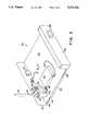
- FIG. 2is a perspective view of a receiver of the embodiment of FIG. 1 employing a quarter wave receiving antenna;
- FIG. 3is a partially broken away perspective view of the receiver of FIG. 2 from which an upper housing member has been removed for illustrating a portion of the interior thereof;
- FIG. 4is a partially broken away, sectional view taken along the lines 4--4 in FIG. 3;
- FIG. 5is a perspective view of the receiver illustrated in FIG. 2 employing a directional yagi-type receiving antenna in place of the quarter wave antenna illustrated in FIG. 2;
- FIG. 6is a partially block, partially schematic diagram of the receiver illustrated in FIGS. 1-5;
- FIG. 7is a block diagram of a television receiver capable of receiving television broadcast band signals and local wireless transmission within a frequency band of 902 MHz to 928 MHz in accordance with another embodiment of the present invention.
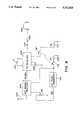
- FIG. 8is a partially block, partially schematic diagram of a stereophonic FM audio receiver for receiving high fidelity audio signals from a local wireless FM audio transmitter at a frequency within the 902 MHz to 928 MHz frequency band.
- a signal sourcesuch as a VCR 20 outputs baseband video signals at a first output 22 and baseband audio signals at a second output 24. It will be appreciated that any other suitable source of video and/or audio signals, such as a video disk player, computer, etc., may replace the VCR 20 in the embodiment of FIG. 1.
- a transmitter 26has a first input coupled with the output 22 to receive the baseband video signals and a second input coupled with the output 24 to receive the baseband audio signals and is operative to modulate a selectable carrier thus to produce a modulated carrier having a frequency of either 912 MHz or 922 MHz and output the modulated carrier to a transmitting antenna 30. More specifically, transmitter 26 includes a modulator which is provided with the baseband video and audio signals and serves to selectably produce a conventionally modulated television signal within either television broadcast channel 3 or channel 4, as established by the United States Federal Communications Commission. The conventional television signal in turn modulates the selected carrier to produce the transmitters output signal at either 912 MHz or 922 MHz, as the user selects.
- the transmitter 26is likewise capable of receiving an input signal within either television broadcast channel 3 or channel 4 to directly modulate the carrier.
- the transmitter 26is operative to convert a television signal including audio and video signal components to an upconverted television signal within the 902 MHz-928 MHz local transmission frequency band.
- transmitting antenna 30is a quarter wave, non-directional transmitting antenna.
- the transmitter poweris limited to 500 microwatts, also in accordance with such regulations.
- Such restrictionsare intended to limit the radiated power in order to minimize interference between local wireless transmission systems sharing the same transmission frequencies. It will be appreciated, therefore, that the wireless transmission distance is thereby substantially restricted, placing a premium on receiver performance.
- a receiving antenna 32is coupled with an antenna input of a receiver 34.
- the receiving antenna 32receives radiated signals from the transmitting antenna 30, providing the same as an input signal to the receiver 34.
- the receiver 34is operative to amplify the received signals, select the desired signals within the 902-928 MHz frequency band and downconvert the selected signals selectably either to television broadcast channel 3 or channel 4.
- the downconverted signalsare provided by the receiver 34 at an output terminal 36 thereof coupled with a first fixed input terminal of an A/B switch 38.
- a second fixed terminal of the A/B switch 38is coupled with an output of a cable converter 40, while a moveable terminal of the A/B switch 3 is coupled with the antenna input terminal of a television receiver 42. Accordingly, when the switch 38 is in the position illustrated in FIG. 1, the television receiver is provided with the downconverted signals from the output 36 of the receiver 34, so that the output of the VCR 20 (or an alternative source of programming) is made available for viewing with the use of the television receiver 42 without the need for a hard wired connection therebetween.
- the receiving antenna 32is mounted on the receiver 34 which is operative to support at least one of two different receiving antennas.
- a useris afforded the ability to select either a non-directional quarter wave receiving antenna or a directional yagi-type receiving antenna providing additional gain where, for example, there is a relatively large distance between the transmitting antenna and the receiving antenna or the presence of intervening objects, resulting in a low signal level at the receiving antenna.
- the usermay instead select the non-directional quarter wave receiving antenna which occupies less space and does not require user adjustment as in the case of the directional antenna.
- the receiver 34includes a housing 44 for enclosing the receiver and having an upper surface 46 and a front panel 48.
- a button of an ON/OFF switch 50is mounted on the front panel 48.
- a quarter wave receiving antenna 52extends upwardly from within the housing 44 above the upper surface 46 thereof through an aperture in the upper surface 46 ringed by a protective grommet 54.
- the housing 44 of the receiver 34is illustrated therein from which an upper housing cover has been removed for illustrating certain internal components of the receiver 34 mounted within the housing.
- the housing 44 as illustrated in FIG. 3includes a housing base 56 which includes the front panel 48, a rear panel 60 and a lower member 62 joining the front and rear panels 48 and 60.
- Four housing feet 64ar affixed to the lower member 62 for supporting the housing 44 at rest on an object. Portions of two of the housing feet 64 are illustrated in FIG. 3.
- the receiver 34includes a circuit board 66 mounted on the lower member 62 of the housing base 56 and having a number of circuit components and sub-assemblies mounted thereon for interconnection and support. A number of circuit elements have been omitted from FIG. 3 for purposes of simplicity and clarity.
- a threaded fastener 70has a threaded portion extending upwardly through the circuit board 66, through and electrically coupled with a connecting lug 72 and extending into a socket member 74 made of an insulating material, such as a hard plastic material.
- the socket member 74has a lower, disc-shaped extremity having a threaded central aperture mated with the threads of the threaded fastener 70 thus to retain the threaded fastener, connecting lug 72 and socket member 74 securely on the circuit board 66, so that the socket member 74 and the threaded fastener 70 are supported indirectly by the lower member 6 of the housing base 56 within the enclosure formed thereby.
- the socket member 74also includes an upstanding, generally conically shaped upper portion integrally formed with the lower, disc-shaped portion thereof at a lower extremity of the conically shaped upper portion and extending to an upper extremity forming a generally circular upwardly facing socket aperture aligned with the aperture formed in the upper surface 46 of the housing 44 (refer also to FIG. 2).
- the threaded fastener 70is aligned with a central axis of the conically shaped upper portion of the socket member 74.
- the quarter wave receiving antenna 52includes a cylindrical body member 75 and a connector 76 affixed to a lower extremity of the cylindrical body member 75.
- the connector 76has a central, downwardly facing aperture formed coaxially with the cylindrical body member 75.
- the central aperture of the connector 76is threaded to mate with the threads of the threaded fastener 70 thus to support the quarter wave receiving antenna 52 vertically such that it extends above the upwardly facing surface 46 through the aperture formed therein, while permitting the quarter wave receiving antenna 52 to be readily disengaged from the threaded fastener 70.
- a first cable-type connector 80is mounted on the rear panel 60 of the housing 44 and has an interconnecting lug 82 provided for connecting with the inner conductor of a shielded cable coupled with the connector 80.
- the interconnecting lug 82is conductively connected with the connecting lug 72 by a wire and is also connected with the central conductor of a coaxial cable 84.
- the coaxial cable 84is provided with an outer, shielding conductor connected with a further connecting lug 86 affixed to an outer conductive portion of the cable-type connector 80 for grounding the outer conductive shield of the coaxial cable 84.
- An opposing end of the central conductor within the coaxial cable 84is connected with an input terminal 90 of the receiver 34 coupled with UHF input circuitry thereof enclosed by an RF shield 92.
- the outer conductive shield of the coaxial cable 84is conductively coupled with a connecting lug formed on the exterior of the RF shield 92.
- the RF shield 92is mounted on the circuit board 66 for supporting the circuitry enclosed thereby, as well as the input terminal 90, on the circuit board 66. It will be appreciated, therefore, that the quarter wave receiving antenna 52 is thereby conductively coupled through the threaded fastener 70, connecting lug 72, interconnecting lug 82, and coaxial cable 84 with the input terminal 90 of the receiver 34.
- the quarter wave receiving antenna 52 illustrated in FIGS. 2-4has been replaced in FIG. 5 by a directional yagi-type receiving antenna 96.
- the directional receiving antenna 96includes an active loop element 98 mounted on an antenna frame member 100, a passive reflector element 102 mounted on the frame member 100, and three passive director elements 104 also mounted on the frame member 100.
- the elements 98, 102 and 104are disposed in a common vertical plane and the directional receiving antenna is operative to provide the greatest gain to received signals polarized in such vertical plane and originating from a source to which an arrow 106 formed at a forward extremity of the antenna frame member 100 points.
- the antenna frame member 100is affixed to an antenna base 108 which, in turn, is affixed to a first half of a hinged member 110.
- a second half of the hinged member 110is formed by an upper extremity of a vertically extending supporting mast 112.
- the first and second halves of the hinged member 110are joined by a horizontally disposed threaded connector 114 extending through an aperture in the second half of the hinged member at the upper extremity of the supporting mast 112 to the first half of the hinged member 110 where the threads of the threaded connector 114 are mated with a threaded aperture provided therein.
- the threaded connector 114serves to releasably hold the first and second halves of the hinged member 110 in a predetermined rotational relationship when the threaded connector is tightened thus to enable the user to selectably determine the rotational attitude of the directional receiving antenna 96 in the common vertical plane of the elements 98, 102 and 104.
- the directional receiving antenna 96may be pivoted vertically to face in the direction of a signal source emitting a signal polarized in the common vertical plane of the receiving antenna 96, thus to optimize the reception of the signal thereby.
- the supporting mast 112is constructed of an insulating material such as a hard plastic and is provided at a lower extremity thereof, indicated at 116, with a projecting pin configured to fit closely within the socket member 74 such that it is rotatable therein while frictionally resisting such rotation. Since the supporting mast 112 is constructed of an insulating material, it does not load the input 90 of the receiver 34 through the threaded fastener 70. Since the directional receiving antenna 9 is affixed to the supporting mast 112 through the hinged member 110, it will be seen that rotation of the pin 116 in the socket member 74 will thereby effect rotation of the directional receiving antenna 96 horizontally to permit positioning thereof in a horizontal direction for pointing the directional receiving antenna 96 toward a desired signal source. Once the horizontal direction of the antenna 96 is thus selected, the frictional resistance between the projecting pin 116 and the socket member 74 tends to maintain the selected horizontal disposition of the directional receiving antenna 96.
- the supporting mast 112is mounted apart from the socket member 74.
- either separate antenna coupling devicesare provided for coupling the respective antennas with the receiver input, or a common coupling device is provided.
- a directional antenna coupleris provided in the for of a shielded cable 118 conductively coupled with the active loop element 98 of the antenna 96 through the antenna base 108 which also supplies strain relief for the shielded cable 118 thus to protect the connection thereof with the element 98.
- the shielded cable 118is provided with a cable connector at a second extremity thereof (not shown for purposes of simplicity and clarity). With reference also to FIG. 3, the cable connector at the second extremity of the shielded cable is adapted to couple conductively with the cable connector 80 mounted on the rear panel 60 of the housing base 56 thus to electrically connect the active loop element 98 of the antenna 96 with the receiver input terminal 90.
- a radio frequency (RF) input amplifier 122has an input coupled with the input terminal 90 of the receiver 34.
- RFradio frequency
- Amplifier 122is a low noise RF amplifier operative to boost the level of the signals received from the antenna 32 and to establish an advantageously high signal-to-noise (S/N) ratio.
- Amplifier 122includes an impedance matching network for matching the impedance of the antenna 32 with the input impedance of the amplifier 122.
- Amplifier 122has a AGC input for receiving an automatic gain control voltage produced in conventional fashion for adjusting the gain of amplifier 122 in accordance with the level of the received signals.
- Amplifier 122provides the amplified signals at an output thereof coupled with the input of a tunable tank circuit 124 in accordance with one aspect of the present invention, which serves to pass substantially only those of the amplified signals from the amplifier 122 within a selectable one of two predetermined pass bands within the 902-928 MHz local transmission band.
- two such predetermined pass bandsare provided, one each centered at 912 MHz and 922 MHz.
- three such predetermined pass bandsare provided within the 902-928 MHz band. The foregoing capabilities of providing plural pass bands within the 902-928 MHz band are effectively achieved by providing the tunable tank circuit 124 in accordance with the presently described embodiment of the invention.
- the tunable tank circuit 124includes a first inductor 126 coupled in parallel with a first varactor diode 128. A first terminal of the inductor 126 together with the anode of the varactor diode 128 ar connected with the output of the amplifier 122. A second terminal of inductor 126 is connected to ground, while the cathode of the varactor diode 128 is coupled through a first RF bypass capacitor 130 to ground. Capacitor 130 also provides DC blocking to permit the application of a variable DC voltage level to the cathode of the varactor diode 128 for tuning the tank circuit 124, as explained in greater detail hereinbelow.
- the first inductor 126is inductively coupled with a second inductor 134 coupled in parallel with a second varactor diode 136. Accordingly, the anode of the varactor diode 136 is connected with a first terminal of the inductor 134, while a second terminal of the inductor 134 is connected to ground.
- the cathode of the varactor diode 136is coupled through a second RF bypass capacitor 138 to ground.
- Capacitor 138like capacitor 130, also provides DC blocking, as explained in greater detail hereinbelow.
- a selectable voltage levelis applied to the cathodes of each of varactor diodes 128 and 136 in order to adjust the capacitance thereof.
- a potentiometer 140is provided having a first fixed terminal provided with a fixed voltage level V and a second fixed terminal connected to ground.
- a wiper arm of the potentiometer 140is coupled with the cathodes of each of varactor diodes 128 and 136 through respective fixed resistors 142 and 144.
- An RF bypass capacitor 146is connected between the wiper arm of the potentiometer 140 and ground.
- the potentiometer 140is illustrated therein mounted on the circuit board 66 adjacent the rear panel 60 having an aperture therein through which a control knob of the potentiometer 140 mechanically coupled with the wiper ar thereof extends to permit the user to adjust the position of the wiper arm thus to tune the tunable tank circuit 124 for selecting a desired channel for reception.
- other equivalent devicesmay be provided for producing the selectable voltage level at the cathodes of the varactor diodes 128 and 136.
- a switched network of fixed resistorscan be provided in place of the potentiometer 140.
- the values of the inductors 126 and 134may be varied.
- Downconversion of the signals selected with the use of the tunable tank circuit 124 to a desired television broadcast bandis achieved by means of a diode mixer 150 which serves to mix the selected signals with a local oscillation voltage produced by a local oscillator 152.
- the frequency of the local oscillation voltagepreferably is maintained at a level higher than that of the selected signals to produce downconverted signals having a frequency determined as the difference between the frequency of the local oscillator voltage and that of the selected signals.
- the frequency of the local oscillation voltageis selected by means of a third varactor diode 154 having its cathode coupled through a fixed resistor 156 with the wiper arm of the potentiometer 140.
- the diode mixer 150has a first input coupled with the second inductor 134 and the second varactor diode 136 of the tunable tank circuit 124 and a second input thereof is coupled with the local oscillator to receive the local oscillation voltage therefrom.
- the mixer 150subjects the downconverted signals to low pass filtering and provides the filtered, downconverted signals at an output 158 thereof.
- RF amplifier 122, tunable tank circuit 124, diode mixer 150 and local oscillatorare enclosed within RF shield 92 illustrated in FIG. 3.
- a tuned output amplifier 160has an input coupled with the output 158 of the mixer 150 and serve both to amplify the downconverted signals and attenuate out-of-band signals which may be present at the output 158.
- the downconverted signals amplified by the output amplifier 160are provided thereby to an output terminal 162 of the receiver 34.
- the antenna input of a conventional television receivermay be coupled with the output terminal 162 and tuned to the broadcast channels of the signals output thereby in order to receive the downconverted signals from the receiver 34.
- a conventional UHF television broadcast band tuner circuitwhich includes a tuning means for selecting signals for reception within a predetermined one of a plurality of UHF television broadcast channels and converter means for converting the received signals to intermediate frequency signals within a television intermediate frequency band.
- a Samsung Electro-Mechanics Co., Ltd. Model EBC-7731AL electronic tunermay be provided for this purpose.
- the conventional electronic tunerincludes an RF input amplifier having an antenna input and an output coupled to a tunable tank circuit which, however, has an upper frequency limit below 900 MHz.
- the tunable tank circuitincludes a first varactor diode coupled in parallel with a first inductor which in turn is inductively coupled with a second inductor coupled in parallel with a second varactor diode.
- the resonant frequency of the tunable tank circuitis determined by adjusting a voltage level applied to the two varactor diodes.
- the output of the tunable tank circuitis provided to a diode mixer which serves to mix the signals selected within the UHF television broadcast channels below 900 MHz with a local oscillation voltage produced by a local oscillator in order to downconvert the UHF broadcast channel signals to a television intermediate frequency signal output by the diode mixer.
- the frequency of the local oscillatoris adjusted by means of an adjustable voltage level applied to a varactor diode thereof simultaneously with the application of the variable voltage level to the varactor diodes of the tunable tank circuit.
- the conventional electronic tuneralso includes a television intermediate frequency amplifier which receives the intermediate frequency signal from the diode mixer and serves to both amplify the same and attenuate signals falling outside the television intermediate frequency band.
- a tuning parameter of the tunable tank circuit of the conventional tuneris modified to provide a television-type tuner operative to select signals for reception within the frequency band extending from 902 MHz to 928 MHz. It has been found by the applicant that the tunable tank circuit of the conventional television tuner ma be appropriately modified for this purpose by reducing the inductance of the two inductors of the tunable tank circuit, for example, by separating the terms thereof and by adjusting the voltage levels applied to the two varactor diodes thereof.
- the frequency of the local oscillation voltageis shifted upwardly so that the difference in frequency between the local oscillation voltage and the signal frequencies of the signals selected by the tunable tank circuits yields signal frequencies of the downconverted signals provided by the diode mixer falling within a predetermined television broadcast band.
- the intermediate frequency amplifieris modified to accept frequencies for amplification within the television broadcast band, rather than the intermediate frequency band, by shifting the resonant frequency of tuning circuits included therein and also by broadening the response thereof, for example, by coupling a resistor in parallel thereacross.
- a parameter of the frequency converter of the conventional television tuneris modified so that it is operative to downconvert the received signals to a predetermined audio broadcast frequency band.
- Corresponding modificationsare effected in the television intermediate frequency amplifier to accept and amplify signals output by the converter within the predetermined audio broadcast frequency band.
- a television receiver in accordance with a further aspect of the present inventionhaving an antenna input terminal 170 coupled with the input of a combined 902 to 928 MHz tuner and television broadcast band tuner 172.
- the combined tuner 172includes a UHF television tuner operative to receive both television broadcast band signals and wireless local transmission signals within the 902 to 928 MHz band.
- the received signalsare downconverted by the combined tuner 172 to a television intermediate frequency band and supplied to the input of conventional television intermediate frequency circuits and detection circuits 174 which serve to amplify the intermediate frequency television signals and demodulate the audio and video signals included therein.
- the demodulated video signalsar supplied to conventional video and synchronization circuits 176 operative to produce a plurality of output signals for application to a conventional television picture tube 178.
- the demodulated audio signals produced by the intermediate frequency circuits 174are supplied to the input of conventional audio frequency circuits 180 which serve to amplify the audio frequency signals and supply the same either as monaural or stereo audio signals to a pair of speakers 182.
- the receiverincludes a receiving antenna 200 coupled with the input of a 902 to 928 MHz receiver 202 of the type disclosed hereinabove which is operative to produce downconverted output signals at a frequency of 35 MHz at an output terminal thereof.
- the output terminal of the receiver 202is coupled with an input of an FM audio receiver 204 which is tuned to 35 MHz and is operative to decode and output stereo audio signals which it provides at an output thereof coupled with a stereo headphone jack 206.
- a nine volt battery 208 and a three volt battery 210comprise a portable power source for operating the circuits illustrated in FIG. 8.
- a negative terminal of the nine volt battery 208is coupled with ground and the positive terminal thereof is coupled with a first pole 212 of an ON/OFF switch.
- the D.C. to D.C. converter 214is operative to convert the nine volt input to a thirty-three volt output which is coupled with a first fixed terminal of a potentiometer 216.
- a second fixed terminal of the potentiometer 216is connected with ground, while a wiper arm thereof is coupled with a tuning voltage input of the receiver 202.
- Potentiometer 216 together with D.C. to D.C. converter 214act as a selectably variable voltage source for tuning the receiver 202 in order to select from one or more audio signals wirelessly transmitted within the 902-928 MHz band.
- a negative terminal of the three volt battery 210is connected with ground and the positive terminal thereof is connected with a second pole 218 of the ON/OFF switch which is operative in the ON position to supply power to the FM audio receiver 204.
- Poles 212 and 218 of the ON/OFF switchare ganged for operation in tandem.
- the FM audio receiver 204is provided with a volume control in the form of a potentiometer 220 and a light emitting diode 222 for indicating the proper reception of a stereo audio signal by the FM audio receiver 204.
- the circuit of FIG. 8is coupled with either one or a pair of remotely located speakers to receive locally transmitted audio signals from a source, such as a home high fidelity system located elsewhere in a house, to provide to the speaker or speakers.
- a sourcesuch as a home high fidelity system located elsewhere in a house
- a listeneris able to receive, for example, high fidelity audio signals from a permanently located source, such as compact disc player, without the need for a hardwired connection thereto.
- the receiver of the present inventionby providing the ability to select from two or more frequency bands within the 902-928 MHz band, has widespread application where the need for local signal transmission exists. For example, a pair of differently tuned transmitters each transmitting a different television signal may be selected for viewing at a nearby location without the need for a hardwired connection to such programming source.
- each cameramay be provided with a corresponding transmitter transmitting over a respectively different frequency band within the 902-928 band MHz local wireless transmission band.
- the system of the present inventionmay be employed for transmitting digital data, for example, for implementing a computerized security system.
Landscapes
- Engineering & Computer Science (AREA)
- Signal Processing (AREA)
- Computer Networks & Wireless Communication (AREA)
- Multimedia (AREA)
- Input Circuits Of Receivers And Coupling Of Receivers And Audio Equipment (AREA)
Abstract
Description
Claims (21)
Priority Applications (4)
| Application Number | Priority Date | Filing Date | Title |
|---|---|---|---|
| US07/665,772US5272525A (en) | 1991-03-07 | 1991-03-07 | System for local wireless transmission of signals at frequencies above 900 MHz |
| US07/982,889US5349386A (en) | 1991-03-07 | 1992-11-30 | Wireless signal transmission systems, methods and apparatus |
| US08/427,450US5666658A (en) | 1991-03-07 | 1995-04-24 | Wireless signal transmission system, method and apparatus |
| US08/839,356US6215981B1 (en) | 1991-03-07 | 1997-04-17 | Wireless signal transmission system, method apparatus |
Applications Claiming Priority (1)
| Application Number | Priority Date | Filing Date | Title |
|---|---|---|---|
| US07/665,772US5272525A (en) | 1991-03-07 | 1991-03-07 | System for local wireless transmission of signals at frequencies above 900 MHz |
Related Child Applications (1)
| Application Number | Title | Priority Date | Filing Date |
|---|---|---|---|
| US82259892AContinuation-In-Part | 1991-03-07 | 1992-01-17 |
Publications (1)
| Publication Number | Publication Date |
|---|---|
| US5272525Atrue US5272525A (en) | 1993-12-21 |
Family
ID=24671523
Family Applications (1)
| Application Number | Title | Priority Date | Filing Date |
|---|---|---|---|
| US07/665,772Expired - LifetimeUS5272525A (en) | 1991-03-07 | 1991-03-07 | System for local wireless transmission of signals at frequencies above 900 MHz |
Country Status (1)
| Country | Link |
|---|---|
| US (1) | US5272525A (en) |
Cited By (39)
| Publication number | Priority date | Publication date | Assignee | Title |
|---|---|---|---|---|
| EP0767531A1 (en)* | 1995-07-31 | 1997-04-09 | Matsushita Electric Industrial Co., Ltd. | A microwave oscillation circuit and a down converter using the same |
| WO1997019558A1 (en)* | 1995-11-22 | 1997-05-29 | Sensormatic Electronics Corporation | Video surveillance apparatus and system |
| US5666159A (en)* | 1995-04-24 | 1997-09-09 | Eastman Kodak Company | Electronic camera system with programmable transmission capability |
| US5768696A (en)* | 1995-12-18 | 1998-06-16 | Golden Eagle Electronics Manufactory Ltd. | Wireless 900 MHz monitor system |
| US5815108A (en)* | 1996-12-18 | 1998-09-29 | Terk Technologies Corporation | System for extending infrared remote control |
| US5835128A (en)* | 1996-11-27 | 1998-11-10 | Hughes Electronics Corporation | Wireless redistribution of television signals in a multiple dwelling unit |
| US5852437A (en)* | 1996-09-24 | 1998-12-22 | Ast Research, Inc. | Wireless device for displaying integrated computer and television user interfaces |
| US6014110A (en)* | 1997-04-11 | 2000-01-11 | Hughes Electronics Corporation | Antenna and method for receiving or transmitting radiation through a dielectric material |
| US6100853A (en)* | 1997-09-10 | 2000-08-08 | Hughes Electronics Corporation | Receiver/transmitter system including a planar waveguide-to-stripline adapter |
| US6104908A (en)* | 1997-02-28 | 2000-08-15 | Hughes Electronics Corporation | System for and method of combining signals of combining signals of diverse modulation formats for distribution in multiple dwelling units |
| US6256303B1 (en) | 1999-10-15 | 2001-07-03 | Akoo, Inc. | Wireless broadcast link to remote receiver |
| US20020006205A1 (en)* | 1999-11-16 | 2002-01-17 | Vincent Lam Man Tai | Method and apparatus for high fidelity wireless stereophonic transmission utilizing dual frequency carriers |
| US20020090198A1 (en)* | 2000-12-27 | 2002-07-11 | Scott Rosenberg | Advertisements in a television recordation system |
| US6424371B1 (en)* | 1997-09-24 | 2002-07-23 | Sheree H. Wen | Intelligent video monitor system |
| US20020097235A1 (en)* | 2000-10-15 | 2002-07-25 | Rosenberg Scott A. | Method and system for dynamic ad placement |
| US20020143996A1 (en)* | 2001-03-29 | 2002-10-03 | Vic Odryna | Passive video multiplexing method and apparatus priority to prior provisional application |
| US6466832B1 (en) | 1998-08-24 | 2002-10-15 | Altec Lansing R & D Center Israel | High quality wireless audio speakers |
| US6504443B1 (en) | 2000-05-17 | 2003-01-07 | Nec America, Inc., | Common anode varactor tuned LC circuit |
| US6658115B1 (en) | 1999-11-16 | 2003-12-02 | Radioshack, Corp. | Method and apparatus for high fidelity wireless stereophonic transmission |
| US20030222990A1 (en)* | 2002-05-29 | 2003-12-04 | John Driska | Video camera for transmitting video, audio and control signals to a remote recording device |
| US20050270429A1 (en)* | 2004-06-04 | 2005-12-08 | Alps Electric Co., Ltd. | Television tuner which can obtain sufficient receiving sensitivity even when receiving FM broadcasting signal |
| US6993283B1 (en) | 2001-07-16 | 2006-01-31 | Nasaco Electronics (Hong Kong) Ltd. | Wireless audio transmission system |
| US7095866B1 (en) | 2001-07-11 | 2006-08-22 | Akoo, Inc. | Wireless 900 MHz broadcast link |
| US20060250319A1 (en)* | 2005-05-06 | 2006-11-09 | Ooi Sooliam L | Antenna apparatus and method of forming same |
| US7212787B2 (en) | 2001-11-29 | 2007-05-01 | Nasaco Electronics (Hong Kong) Ltd. | Wireless audio transmission system |
| US20070153806A1 (en)* | 2005-12-30 | 2007-07-05 | Tomasz Celinski | Media data transfer in a network environment |
| WO2007084990A3 (en)* | 2006-01-20 | 2008-05-22 | Intellectual Solutions Inc | Camera and display device for use with vehicles |
| USD584308S1 (en) | 2008-03-20 | 2009-01-06 | Johnson Jr James M | Wireless transmitter |
| US7539889B2 (en) | 2005-12-30 | 2009-05-26 | Avega Systems Pty Ltd | Media data synchronization in a wireless network |
| US7698723B2 (en) | 2000-12-28 | 2010-04-13 | At&T Intellectual Property I, L.P. | System and method for multimedia on demand services |
| US8009173B2 (en) | 2006-08-10 | 2011-08-30 | Avocent Huntsville Corporation | Rack interface pod with intelligent platform control |
| US8269783B2 (en) | 1999-08-25 | 2012-09-18 | Avocent Redmond Corporation | KVM switch including a terminal emulator |
| US8427489B2 (en) | 2006-08-10 | 2013-04-23 | Avocent Huntsville Corporation | Rack interface pod with intelligent platform control |
| US8494474B1 (en) | 2010-11-29 | 2013-07-23 | The United States Of America As Represented By The Secretary Of The Navy | Dual band diode mixer for RF data receiver |
| US8601519B1 (en) | 2000-12-28 | 2013-12-03 | At&T Intellectual Property I, L.P. | Digital residential entertainment system |
| US8677423B2 (en) | 2000-12-28 | 2014-03-18 | At&T Intellectual Property I, L. P. | Digital residential entertainment system |
| US20140347091A1 (en)* | 2011-12-26 | 2014-11-27 | Hyosung Corporation | Device for detecting partial discharge for power transformer |
| US9769551B2 (en) | 2014-12-31 | 2017-09-19 | Skullcandy, Inc. | Method of connecting cable to headphone, and headphone formed using such methods |
| US20240080062A1 (en)* | 2022-09-07 | 2024-03-07 | Qualcomm Incorporated | Internal transmit/receive switch with hardware reuse |
Citations (24)
| Publication number | Priority date | Publication date | Assignee | Title |
|---|---|---|---|---|
| US2287065A (en)* | 1940-03-29 | 1942-06-23 | Rca Corp | Modulation and relay |
| US2508853A (en)* | 1945-04-12 | 1950-05-23 | Rca Corp | Radio relaying |
| US2831105A (en)* | 1952-04-07 | 1958-04-15 | Louis W Parker | Television distribution system |
| US3697941A (en)* | 1971-07-01 | 1972-10-10 | Devenco Inc | Vehicle location system and method |
| US3984625A (en)* | 1966-04-25 | 1976-10-05 | Iit Research Institute | Portable video recording system employing camera and recording stations connected by a wireless link |
| US4097893A (en)* | 1966-04-25 | 1978-06-27 | Iit Research Institute | Portable video recording system employing camera and recording stations connected by wireless links |
| US4145720A (en)* | 1976-07-22 | 1979-03-20 | Morton Weintraub | Remote control |
| US4259746A (en)* | 1979-10-26 | 1981-03-31 | Sandstedt Gary O | Electrical communications system |
| US4386436A (en)* | 1981-02-27 | 1983-05-31 | Rca Corporation | Television remote control system for selectively controlling external apparatus through the AC power line |
| US4392022A (en)* | 1981-01-30 | 1983-07-05 | Rca Corporation | Television remote control system for selectively controlling a plurality of external apparatus |
| US4417279A (en)* | 1981-02-16 | 1983-11-22 | Hitachi, Ltd. | FM Television signal receiving circuit |
| US4434510A (en)* | 1978-03-10 | 1984-02-28 | Lemelson Jerome H | Communication system and method |
| US4549179A (en)* | 1983-03-04 | 1985-10-22 | Stendardo William J | Apparatus for remote control of volume and power on electronic equipment possessing an audio output |
| US4605968A (en)* | 1983-07-21 | 1986-08-12 | Sony Corporation | Direct broadcasting satellite receiver |
| US4621374A (en)* | 1981-12-24 | 1986-11-04 | Itt Industries, Inc. | Circuit arrangement for processing, transmitting, and acoustically reproducing digitized audio-frequency signals |
| US4658438A (en)* | 1984-09-17 | 1987-04-14 | Alps Electric Co., Ltd. | Receiver for satellite broadcasting service |
| US4685133A (en)* | 1985-09-16 | 1987-08-04 | Inr Technologies, Inc. | Wireless audio transmission system |
| US4694338A (en)* | 1986-04-25 | 1987-09-15 | North American Philips Corporation | High-definition television transmission system |
| US4739413A (en)* | 1985-06-14 | 1988-04-19 | Luma Telecom, Inc. | Video-optimized modulator-demodulator with adjacent modulating amplitudes matched to adjacent pixel gray values |
| US4771344A (en)* | 1986-11-13 | 1988-09-13 | James Fallacaro | System for enhancing audio and/or visual presentation |
| US4916532A (en)* | 1987-09-15 | 1990-04-10 | Jerry R. Iggulden | Television local wireless transmission and control |
| US4980665A (en)* | 1987-05-22 | 1990-12-25 | Recoton Corporation | Remote control repeater |
| US4984296A (en)* | 1988-02-11 | 1991-01-08 | Larry Schotz | Tuned radio apparatus |
| US5047860A (en)* | 1990-06-01 | 1991-09-10 | Gary Rogalski | Wireless audio and video signal transmitter and receiver system apparatus |
- 1991
- 1991-03-07USUS07/665,772patent/US5272525A/ennot_activeExpired - Lifetime
Patent Citations (24)
| Publication number | Priority date | Publication date | Assignee | Title |
|---|---|---|---|---|
| US2287065A (en)* | 1940-03-29 | 1942-06-23 | Rca Corp | Modulation and relay |
| US2508853A (en)* | 1945-04-12 | 1950-05-23 | Rca Corp | Radio relaying |
| US2831105A (en)* | 1952-04-07 | 1958-04-15 | Louis W Parker | Television distribution system |
| US3984625A (en)* | 1966-04-25 | 1976-10-05 | Iit Research Institute | Portable video recording system employing camera and recording stations connected by a wireless link |
| US4097893A (en)* | 1966-04-25 | 1978-06-27 | Iit Research Institute | Portable video recording system employing camera and recording stations connected by wireless links |
| US3697941A (en)* | 1971-07-01 | 1972-10-10 | Devenco Inc | Vehicle location system and method |
| US4145720A (en)* | 1976-07-22 | 1979-03-20 | Morton Weintraub | Remote control |
| US4434510A (en)* | 1978-03-10 | 1984-02-28 | Lemelson Jerome H | Communication system and method |
| US4259746A (en)* | 1979-10-26 | 1981-03-31 | Sandstedt Gary O | Electrical communications system |
| US4392022A (en)* | 1981-01-30 | 1983-07-05 | Rca Corporation | Television remote control system for selectively controlling a plurality of external apparatus |
| US4417279A (en)* | 1981-02-16 | 1983-11-22 | Hitachi, Ltd. | FM Television signal receiving circuit |
| US4386436A (en)* | 1981-02-27 | 1983-05-31 | Rca Corporation | Television remote control system for selectively controlling external apparatus through the AC power line |
| US4621374A (en)* | 1981-12-24 | 1986-11-04 | Itt Industries, Inc. | Circuit arrangement for processing, transmitting, and acoustically reproducing digitized audio-frequency signals |
| US4549179A (en)* | 1983-03-04 | 1985-10-22 | Stendardo William J | Apparatus for remote control of volume and power on electronic equipment possessing an audio output |
| US4605968A (en)* | 1983-07-21 | 1986-08-12 | Sony Corporation | Direct broadcasting satellite receiver |
| US4658438A (en)* | 1984-09-17 | 1987-04-14 | Alps Electric Co., Ltd. | Receiver for satellite broadcasting service |
| US4739413A (en)* | 1985-06-14 | 1988-04-19 | Luma Telecom, Inc. | Video-optimized modulator-demodulator with adjacent modulating amplitudes matched to adjacent pixel gray values |
| US4685133A (en)* | 1985-09-16 | 1987-08-04 | Inr Technologies, Inc. | Wireless audio transmission system |
| US4694338A (en)* | 1986-04-25 | 1987-09-15 | North American Philips Corporation | High-definition television transmission system |
| US4771344A (en)* | 1986-11-13 | 1988-09-13 | James Fallacaro | System for enhancing audio and/or visual presentation |
| US4980665A (en)* | 1987-05-22 | 1990-12-25 | Recoton Corporation | Remote control repeater |
| US4916532A (en)* | 1987-09-15 | 1990-04-10 | Jerry R. Iggulden | Television local wireless transmission and control |
| US4984296A (en)* | 1988-02-11 | 1991-01-08 | Larry Schotz | Tuned radio apparatus |
| US5047860A (en)* | 1990-06-01 | 1991-09-10 | Gary Rogalski | Wireless audio and video signal transmitter and receiver system apparatus |
Non-Patent Citations (21)
| Title |
|---|
| "New 902-928 MHz Band Now Open!", Spec-Com Journal, Sep./Oct. 1985, cover page and page 9. |
| "Reference Data for Engineers: Radio, Electronics, Computer and Communications", Howard W. Sams & Co., Inc., 7th Edition, 1986, cover page, and pp. 1-5, 1-18 and 35-10 through 35-15. |
| "TVC-9 GaAs FET 33 cm ATV Downconverter", Spec-Com Journal, Sep./Oct. 1986, cover page and pp. 20-21. |
| 1981 Radio Amateur s Handbook, published by the American Radio Relay League, cover page and pp. 14 28 to 14 33.* |
| 1981 Radio Amateur's Handbook, published by the American Radio Relay League, cover page and pp. 14-28 to 14-33. |
| E. Laird Campbell, "Amateur TV-The Easy Way", QST Magazine, Nov. 1962, pp. 33-41 and 150. |
| E. Laird Campbell, Amateur TV The Easy Way , QST Magazine, Nov. 1962, pp. 33 41 and 150.* |
| FCC Public Notice Report No. 1544, Oct. 21, 1985 (two pages) and certification that the same is a true and correct copy.* |
| Federal Register, vol. 50, Aug. 22, 1985, Final Rulemaking re addition of 902 928 MHz band to Amateur Radio Service Rules, pp. 33937 through 33940.* |
| Federal Register, vol. 50, Aug. 22, 1985, Final Rulemaking re addition of 902-928 MHz band to Amateur Radio Service Rules, pp. 33937 through 33940. |
| Fenton, Radio Electronics, Nov. 1987, p. 4.* |
| Hap Griffin, "HAM-TV, Amateur Radio's Visual Mode That Blends, Voice, Video, Photography & Experimentation!", A5 Amateur Television Magazine, Sep. 1984, pp. 6-9. |
| Hap Griffin, HAM TV, Amateur Radio s Visual Mode That Blends, Voice, Video, Photography & Experimentation , A5 Amateur Television Magazine, Sep. 1984, pp. 6 9.* |
| Henry B. Ruh, "All About Amateur TV", QST Magazine, Jun. 1981, pp. 11-12. |
| Henry B. Ruh, All About Amateur TV , QST Magazine, Jun. 1981, pp. 11 12.* |
| Jerry Iggulden, Rule Making Petition to Federal Communications Commission, Sept. 11, 1985.* |
| New 902 928 MHz Band Now Open , Spec Com Journal, Sep./Oct. 1985, cover page and page 9.* |
| P. C. Electronics, Advertisement, A5 Amateur Television Magazine, Sep. 1984, cover/table of contents page and pp. 20 23.* |
| P. C. Electronics, Advertisement, A5 Amateur Television Magazine, Sep. 1984, cover/table of contents page and pp. 20-23. |
| Reference Data for Engineers: Radio, Electronics, Computer and Communications , Howard W. Sams & Co., Inc., 7th Edition, 1986, cover page, and pp. 1 5, 1 18 and 35 10 through 35 15.* |
| TVC 9 GaAs FET 33 cm ATV Downconverter , Spec Com Journal, Sep./Oct. 1986, cover page and pp. 20 21.* |
Cited By (57)
| Publication number | Priority date | Publication date | Assignee | Title |
|---|---|---|---|---|
| US8736694B2 (en) | 1995-04-24 | 2014-05-27 | Intellectual Ventures Fund 83 Llc | Transmitting digital images to a plurality of selected receivers over a radio frequency link |
| US5666159A (en)* | 1995-04-24 | 1997-09-09 | Eastman Kodak Company | Electronic camera system with programmable transmission capability |
| US5801590A (en)* | 1995-07-31 | 1998-09-01 | Matsushita Electric Industrial Co., Ltd. | Dielectric resonator oscillator and down converter using the same |
| EP0767531A1 (en)* | 1995-07-31 | 1997-04-09 | Matsushita Electric Industrial Co., Ltd. | A microwave oscillation circuit and a down converter using the same |
| WO1997019558A1 (en)* | 1995-11-22 | 1997-05-29 | Sensormatic Electronics Corporation | Video surveillance apparatus and system |
| US5768696A (en)* | 1995-12-18 | 1998-06-16 | Golden Eagle Electronics Manufactory Ltd. | Wireless 900 MHz monitor system |
| US5852437A (en)* | 1996-09-24 | 1998-12-22 | Ast Research, Inc. | Wireless device for displaying integrated computer and television user interfaces |
| US6553567B1 (en)* | 1996-09-24 | 2003-04-22 | Samsung Electronics Co., Ltd. | Wireless device for displaying integrated computer and television user interfaces |
| US5835128A (en)* | 1996-11-27 | 1998-11-10 | Hughes Electronics Corporation | Wireless redistribution of television signals in a multiple dwelling unit |
| US5815108A (en)* | 1996-12-18 | 1998-09-29 | Terk Technologies Corporation | System for extending infrared remote control |
| USRE38208E1 (en) | 1996-12-18 | 2003-08-05 | Neil D. Terk | System for extending infrared remote control |
| US6104908A (en)* | 1997-02-28 | 2000-08-15 | Hughes Electronics Corporation | System for and method of combining signals of combining signals of diverse modulation formats for distribution in multiple dwelling units |
| US6014110A (en)* | 1997-04-11 | 2000-01-11 | Hughes Electronics Corporation | Antenna and method for receiving or transmitting radiation through a dielectric material |
| US6268781B1 (en) | 1997-09-10 | 2001-07-31 | Hughes Electronics Corporation | Planar waveguide-to-stripline adapter |
| US6100853A (en)* | 1997-09-10 | 2000-08-08 | Hughes Electronics Corporation | Receiver/transmitter system including a planar waveguide-to-stripline adapter |
| US6424371B1 (en)* | 1997-09-24 | 2002-07-23 | Sheree H. Wen | Intelligent video monitor system |
| US6466832B1 (en) | 1998-08-24 | 2002-10-15 | Altec Lansing R & D Center Israel | High quality wireless audio speakers |
| US8269783B2 (en) | 1999-08-25 | 2012-09-18 | Avocent Redmond Corporation | KVM switch including a terminal emulator |
| US6256303B1 (en) | 1999-10-15 | 2001-07-03 | Akoo, Inc. | Wireless broadcast link to remote receiver |
| US20020006205A1 (en)* | 1999-11-16 | 2002-01-17 | Vincent Lam Man Tai | Method and apparatus for high fidelity wireless stereophonic transmission utilizing dual frequency carriers |
| US6658115B1 (en) | 1999-11-16 | 2003-12-02 | Radioshack, Corp. | Method and apparatus for high fidelity wireless stereophonic transmission |
| US7343015B2 (en) | 1999-11-16 | 2008-03-11 | Radio Shack Corporation | Method and apparatus for high fidelity wireless stereophonic transmission utilizing dual frequency carriers |
| US6504443B1 (en) | 2000-05-17 | 2003-01-07 | Nec America, Inc., | Common anode varactor tuned LC circuit |
| US8078493B2 (en) | 2000-10-15 | 2011-12-13 | The Directv Group, Inc. | Method and system for pause ads |
| US10380630B2 (en) | 2000-10-15 | 2019-08-13 | The Directv Group, Inc. | Method and system for dynamic ad placement |
| US20020100041A1 (en)* | 2000-10-15 | 2002-07-25 | Rosenberg Scott A. | Method and system for pause ads |
| US8571934B2 (en) | 2000-10-15 | 2013-10-29 | The Directv Group, Inc. | Method and system for dynamic ad placement |
| US20020097235A1 (en)* | 2000-10-15 | 2002-07-25 | Rosenberg Scott A. | Method and system for dynamic ad placement |
| US8571933B2 (en)* | 2000-12-27 | 2013-10-29 | The Directv Group, Inc. | Advertisements in a television recordation system |
| US20020090198A1 (en)* | 2000-12-27 | 2002-07-11 | Scott Rosenberg | Advertisements in a television recordation system |
| US8601519B1 (en) | 2000-12-28 | 2013-12-03 | At&T Intellectual Property I, L.P. | Digital residential entertainment system |
| US8677423B2 (en) | 2000-12-28 | 2014-03-18 | At&T Intellectual Property I, L. P. | Digital residential entertainment system |
| US7698723B2 (en) | 2000-12-28 | 2010-04-13 | At&T Intellectual Property I, L.P. | System and method for multimedia on demand services |
| US20020143996A1 (en)* | 2001-03-29 | 2002-10-03 | Vic Odryna | Passive video multiplexing method and apparatus priority to prior provisional application |
| US7424551B2 (en) | 2001-03-29 | 2008-09-09 | Avocent Corporation | Passive video multiplexing method and apparatus priority to prior provisional application |
| US7590763B2 (en) | 2001-03-29 | 2009-09-15 | Avocent Corporation | Device for use in a system for processing keyboard, video and mouse signals |
| US7095866B1 (en) | 2001-07-11 | 2006-08-22 | Akoo, Inc. | Wireless 900 MHz broadcast link |
| US6993283B1 (en) | 2001-07-16 | 2006-01-31 | Nasaco Electronics (Hong Kong) Ltd. | Wireless audio transmission system |
| US7212787B2 (en) | 2001-11-29 | 2007-05-01 | Nasaco Electronics (Hong Kong) Ltd. | Wireless audio transmission system |
| US20030222990A1 (en)* | 2002-05-29 | 2003-12-04 | John Driska | Video camera for transmitting video, audio and control signals to a remote recording device |
| US7388622B2 (en)* | 2004-06-04 | 2008-06-17 | Alps Electric Co., Ltd | Television tuner which can obtain sufficient receiving sensitivity even when receiving FM broadcasting signal |
| US20050270429A1 (en)* | 2004-06-04 | 2005-12-08 | Alps Electric Co., Ltd. | Television tuner which can obtain sufficient receiving sensitivity even when receiving FM broadcasting signal |
| US20060250319A1 (en)* | 2005-05-06 | 2006-11-09 | Ooi Sooliam L | Antenna apparatus and method of forming same |
| US7996700B2 (en) | 2005-12-30 | 2011-08-09 | Altec Lansing Australia Pty Limited | Media data synchronization in a wireless network |
| US8462627B2 (en) | 2005-12-30 | 2013-06-11 | Altec Lansing Australia Pty Ltd | Media data transfer in a network environment |
| US20070153806A1 (en)* | 2005-12-30 | 2007-07-05 | Tomasz Celinski | Media data transfer in a network environment |
| US20090204843A1 (en)* | 2005-12-30 | 2009-08-13 | Avega Systems Pty Ltd | Media data synchronization in a wireless network |
| US7539889B2 (en) | 2005-12-30 | 2009-05-26 | Avega Systems Pty Ltd | Media data synchronization in a wireless network |
| WO2007084990A3 (en)* | 2006-01-20 | 2008-05-22 | Intellectual Solutions Inc | Camera and display device for use with vehicles |
| US8009173B2 (en) | 2006-08-10 | 2011-08-30 | Avocent Huntsville Corporation | Rack interface pod with intelligent platform control |
| US8427489B2 (en) | 2006-08-10 | 2013-04-23 | Avocent Huntsville Corporation | Rack interface pod with intelligent platform control |
| USD584308S1 (en) | 2008-03-20 | 2009-01-06 | Johnson Jr James M | Wireless transmitter |
| US8494474B1 (en) | 2010-11-29 | 2013-07-23 | The United States Of America As Represented By The Secretary Of The Navy | Dual band diode mixer for RF data receiver |
| US20140347091A1 (en)* | 2011-12-26 | 2014-11-27 | Hyosung Corporation | Device for detecting partial discharge for power transformer |
| US9726708B2 (en)* | 2011-12-26 | 2017-08-08 | Hyosung Corporation | Device for detecting partial discharge for power transformer |
| US9769551B2 (en) | 2014-12-31 | 2017-09-19 | Skullcandy, Inc. | Method of connecting cable to headphone, and headphone formed using such methods |
| US20240080062A1 (en)* | 2022-09-07 | 2024-03-07 | Qualcomm Incorporated | Internal transmit/receive switch with hardware reuse |
Similar Documents
| Publication | Publication Date | Title |
|---|---|---|
| US5272525A (en) | System for local wireless transmission of signals at frequencies above 900 MHz | |
| US4916532A (en) | Television local wireless transmission and control | |
| US4592093A (en) | Super high frequency receiver | |
| US5101499A (en) | Television local wireless transmission and control | |
| US5243415A (en) | Limited range stereo-audio video RF transmitter to multiple receiver system | |
| US6256303B1 (en) | Wireless broadcast link to remote receiver | |
| US5023931A (en) | Television local wireless transmission and control | |
| US6177963B1 (en) | Video signal distribution system | |
| US5045948A (en) | Television local wireless transmission and control | |
| US5758262A (en) | Apparatus for converting TV audio signals for reception on a nearby AM and/or FM receiver | |
| WO1996005663A1 (en) | Wireless signal transmission systems, method and apparatus | |
| US7584494B2 (en) | Cable to wireless conversion system for in-home video distribution | |
| US4021737A (en) | System for processing and transmitting audio signals received from a television set for reproduction by a high fidelity FM receiver | |
| US4748501A (en) | Cable converter for television signals with stereo audio signal | |
| US7095866B1 (en) | Wireless 900 MHz broadcast link | |
| KR100211620B1 (en) | First IF filter with fixed second half-IF trap used for FM radio in television receiver | |
| US3863157A (en) | Built-in FM dipole antenna | |
| JP2563401B2 (en) | Receiver | |
| US20040130662A1 (en) | Digital television converter | |
| KR20010102273A (en) | Television receiver remote control system with television audio | |
| JP2548716B2 (en) | Wireless remote control booster | |
| RU41939U1 (en) | SERVICE DEVICE FOR WIRELESS AUDIO TRANSMISSION | |
| JP2005065075A (en) | Planar antenna for television | |
| KR200289678Y1 (en) | Apparatus for wireless display | |
| JPH08149382A (en) | Booster |
Legal Events
| Date | Code | Title | Description |
|---|---|---|---|
| AS | Assignment | Owner name:RECOTON CORPORATION, 46-23 CRANE STREET, LONG ISLA Free format text:ASSIGNMENT OF ASSIGNORS INTEREST.;ASSIGNORS:BORCHARDT, ROBERT L.;MC GREEVY, WILLIAM T.;REEL/FRAME:005633/0469 Effective date:19910305 | |
| STCF | Information on status: patent grant | Free format text:PATENTED CASE | |
| FEPP | Fee payment procedure | Free format text:PAYOR NUMBER ASSIGNED (ORIGINAL EVENT CODE: ASPN); ENTITY STATUS OF PATENT OWNER: LARGE ENTITY Free format text:PAT HLDR NO LONGER CLAIMS SMALL ENT STAT AS INDIV INVENTOR (ORIGINAL EVENT CODE: LSM1); ENTITY STATUS OF PATENT OWNER: LARGE ENTITY | |
| FPAY | Fee payment | Year of fee payment:4 | |
| CC | Certificate of correction | ||
| AS | Assignment | Owner name:CHASE MANHATTAN BANK, THE, AS COLLATERAL AGENT, NE Free format text:SECURITY AGREEMENT;ASSIGNOR:RECOTON CORPORATION, A CORPORATION OF NEW YORK;REEL/FRAME:010272/0348 Effective date:19990924 | |
| AS | Assignment | Owner name:RECOTON CORPORATION, FLORIDA Free format text:RELEASE OF SECURITY INTEREST;ASSIGNOR:CHASE MANHATTAN BANK;REEL/FRAME:011122/0511 Effective date:20001031 | |
| FEPP | Fee payment procedure | Free format text:PAYOR NUMBER ASSIGNED (ORIGINAL EVENT CODE: ASPN); ENTITY STATUS OF PATENT OWNER: LARGE ENTITY | |
| FEPP | Fee payment procedure | Free format text:PAYER NUMBER DE-ASSIGNED (ORIGINAL EVENT CODE: RMPN); ENTITY STATUS OF PATENT OWNER: LARGE ENTITY | |
| AS | Assignment | Owner name:HELLER FINANCIAL, INC., ILLINOIS Free format text:SECURITY AGREEMENT;ASSIGNORS:RECOTON CORPORATION;INTERACT ACCESSORIES, INC.;AAMP OF FLORIDA, INC.;AND OTHERS;REEL/FRAME:011410/0372 Effective date:20001031 | |
| FPAY | Fee payment | Year of fee payment:8 | |
| AS | Assignment | Owner name:THOMSON LICENSING S.A., FRANCE Free format text:ASSIGNMENT OF ASSIGNORS INTEREST;ASSIGNOR:RECOTON CORPORATION;REEL/FRAME:014268/0101 Effective date:20030710 | |
| FPAY | Fee payment | Year of fee payment:12 |