US5271404A - Method and apparatus for processing signal data to form an envelope on line - Google Patents
Method and apparatus for processing signal data to form an envelope on lineDownload PDFInfo
- Publication number
- US5271404A US5271404AUS07/904,195US90419592AUS5271404AUS 5271404 AUS5271404 AUS 5271404AUS 90419592 AUS90419592 AUS 90419592AUS 5271404 AUS5271404 AUS 5271404A
- Authority
- US
- United States
- Prior art keywords
- frequency
- signal
- peak
- spectra
- velocity
- Prior art date
- Legal status (The legal status is an assumption and is not a legal conclusion. Google has not performed a legal analysis and makes no representation as to the accuracy of the status listed.)
- Expired - Lifetime
Links
Images
Classifications
- A—HUMAN NECESSITIES
- A61—MEDICAL OR VETERINARY SCIENCE; HYGIENE
- A61B—DIAGNOSIS; SURGERY; IDENTIFICATION
- A61B8/00—Diagnosis using ultrasonic, sonic or infrasonic waves
- A61B8/12—Diagnosis using ultrasonic, sonic or infrasonic waves in body cavities or body tracts, e.g. by using catheters
- A—HUMAN NECESSITIES
- A61—MEDICAL OR VETERINARY SCIENCE; HYGIENE
- A61B—DIAGNOSIS; SURGERY; IDENTIFICATION
- A61B8/00—Diagnosis using ultrasonic, sonic or infrasonic waves
- A61B8/06—Measuring blood flow
- G—PHYSICS
- G01—MEASURING; TESTING
- G01P—MEASURING LINEAR OR ANGULAR SPEED, ACCELERATION, DECELERATION, OR SHOCK; INDICATING PRESENCE, ABSENCE, OR DIRECTION, OF MOVEMENT
- G01P5/00—Measuring speed of fluids, e.g. of air stream; Measuring speed of bodies relative to fluids, e.g. of ship, of aircraft
- G01P5/24—Measuring speed of fluids, e.g. of air stream; Measuring speed of bodies relative to fluids, e.g. of ship, of aircraft by measuring the direct influence of the streaming fluid on the properties of a detecting acoustical wave
- G01P5/241—Measuring speed of fluids, e.g. of air stream; Measuring speed of bodies relative to fluids, e.g. of ship, of aircraft by measuring the direct influence of the streaming fluid on the properties of a detecting acoustical wave by using reflection of acoustical waves, i.e. Doppler-effect
- G01P5/244—Measuring speed of fluids, e.g. of air stream; Measuring speed of bodies relative to fluids, e.g. of ship, of aircraft by measuring the direct influence of the streaming fluid on the properties of a detecting acoustical wave by using reflection of acoustical waves, i.e. Doppler-effect involving pulsed waves
- G—PHYSICS
- G01—MEASURING; TESTING
- G01S—RADIO DIRECTION-FINDING; RADIO NAVIGATION; DETERMINING DISTANCE OR VELOCITY BY USE OF RADIO WAVES; LOCATING OR PRESENCE-DETECTING BY USE OF THE REFLECTION OR RERADIATION OF RADIO WAVES; ANALOGOUS ARRANGEMENTS USING OTHER WAVES
- G01S15/00—Systems using the reflection or reradiation of acoustic waves, e.g. sonar systems
- G01S15/88—Sonar systems specially adapted for specific applications
- G01S15/89—Sonar systems specially adapted for specific applications for mapping or imaging
- G01S15/8906—Short-range imaging systems; Acoustic microscope systems using pulse-echo techniques
- G01S15/8977—Short-range imaging systems; Acoustic microscope systems using pulse-echo techniques using special techniques for image reconstruction, e.g. FFT, geometrical transformations, spatial deconvolution, time deconvolution
- G—PHYSICS
- G01—MEASURING; TESTING
- G01S—RADIO DIRECTION-FINDING; RADIO NAVIGATION; DETERMINING DISTANCE OR VELOCITY BY USE OF RADIO WAVES; LOCATING OR PRESENCE-DETECTING BY USE OF THE REFLECTION OR RERADIATION OF RADIO WAVES; ANALOGOUS ARRANGEMENTS USING OTHER WAVES
- G01S15/00—Systems using the reflection or reradiation of acoustic waves, e.g. sonar systems
- G01S15/88—Sonar systems specially adapted for specific applications
- G01S15/89—Sonar systems specially adapted for specific applications for mapping or imaging
- G01S15/8906—Short-range imaging systems; Acoustic microscope systems using pulse-echo techniques
- G01S15/8979—Combined Doppler and pulse-echo imaging systems
Definitions
- This inventionrelates generally to the real time processing of time varying spectral amplitudes to form a temporal envelope of the instantaneous spectral peak frequency.
- spectrogramwhich is a two dimensional gray scale display wherein the abscissa represents time, the ordinate represents frequency and the gray level at a point denotes the amplitude of the corresponding frequency component at that instant of time.
- some deviceshave provided computerized algorithms for determining the instantaneous spectral peak frequency envelope of a spectrogram.
- previous computerized algorithmshave suffered from any of a number of problems.
- One problem with prior art devicesis that they are too complex and therefore they are too slow to provide real time computation of the envelope.
- Another problemis that they are sensitive to the spectral distribution or amplitude.
- Another problem with prior art devicesis that they are sensitive to interference signals which may be present in the spectrogram.
- Yet another typical problem in prior art devicesis that they are sensitive to time varying noise levels.
- Another object of the present inventionis to provide a method and apparatus of the above character for forming an envelope which defines an instantaneous peak velocity waveform.
- Another object of the present inventionis to provide a method and apparatus for real time generation of a spectrogram.
- Another object of the present inventionis to provide a method and apparatus for eliminating interference within a spectrogram.
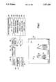
- FIG. 1is a block diagram of an apparatus incorporating the present invention, including a display showing a spectrogram and the envelope formed by the method of the invention.
- the apparatus 20 incorporating the present invention as shown in FIG. 1is used for processing Doppler-shifted ultrasound signals reflected by moving blood cells within a vessel so as to produce a clearly defined blood velocity spectrogram envelope.
- the apparatus 20is for use with any measuring device 24 which produces a signal which varies with time, such as a guide wire having a Doppler ultrasound transducer mounted thereon for measuring blood flow velocity in a human blood vessel, such as disclosed in U.S. Pat. No. 4,967,753.
- the apparatus 20includes a transmitter 30 which supplies RF bursts at a given repetition over line 26 to the device 24 which propagates ultrasonic signals into the blood stream.
- a receiver 28receives the RF signals on line 29 from the device 24 created by reflections of the propagated signals.
- the signals received by the receiver 28vary in frequency and amplitude with time.
- the ultrasound signal from the Doppler transducerpropagate in the forward direction to produce a relatively broad divergent beam that will cover a majority of the area of the vessel lumen.
- a 3 dB (oneway) beam width of 20 to 90 degreesis preferred.
- Such a broad beam, covering the majority of the vessel lumenwill ensure that the peak frequency measured in the Doppler spectrum will correspond to the highest flow velocity within the vessel forward of the ultrasonic transducer, independent of the precise orientation of the transducer.
- the time-varying signal on line 31is conveyed to a sample and hold device 34.
- the sampled signal from the sample/hold device 34is supplied to a Fourier transform device 40 which is preferably a dedicated digital signal processor.
- a short segment of the sampled, time-varying signal on line 35is subjected to a Fourier transformation to provide a frequency spectrum of that segment of the sampled, time-varying signal on line 35.
- a succession of spectrais continuously produced by subjecting subsequent short segments of the sampled, time-varying signal on line 31 to the Fourier transformation.
- Frequency spectra, also referred to as spectra, 42may be generated at a suitable rate such as approximately 100 spectra/second.
- a frequency spectrumcomprises 256 frequency bins. Each frequency bin contains a value which represents the amplitude of the corresponding frequency component of the associated segment of the sampled, time-varying signal on line 35.
- the spectrum provided by the device 40is conveyed to CPU 48 which has associated therewith a memory 50 to process the spectral data.
- the CPU 48may be a general purpose central processing unit (CPU), such as an Intel 80286.
- the CPU 48operates with memory 50 and stores a set of instructions for processing the succession of spectra on line 45.
- the memory 50may be a memory card, ROM, RAM, disc storage or combination thereof and stores a set of instructions which are used as hereinafter described.
- the first step associated with the inventionis to receive the RF signal from the measurement device 24, as previously discussed. Subsequently, spectra are generated, as previously discussed. Thereafter, each spectrum is processed in accordance with the invention, to identify the peak frequency bin which has a significant amplitude above the background noise level.
- the difficulty of identifying this peak frequencyresults from a number of factors including: the timevarying background noise level, electrical interference signals, and transient noise spikes.
- the peak frequency within each spectrummust be determined within the time required to generate the next spectrum, in order to provide an on line instantaneous peak frequency envelope.
- the first stepis to apply a narrowband interference filter 62 to the spectral data.
- This filterwill attenuate narrowband spectral values contributed by external electronic interference signals which give rise to horizontal lines in the spectrogram display, and it will prevent the subsequent steps of the invention form tracking those horizontal interference lines.
- a pseudo code implementation of this filterfollows:
- narrowband interferenceis defined as a bin with spectral value greater than a threshold and bounded above and below by nearby bins with spectral values below a threshold defined relative to the spectral value of the bin under evaluation.
- This patternis typical of interference generated by electronic instrumentation; it is not the pattern typical of the Doppler spectrum of flowing blood. This distinction permits the removal of external electronic interference without affecting the frequency information from the blood Doppler signal.
- a signal-to-noise ratiois preferably calculated by SNR calculator 64.
- the calculation of the signal-to-noise ratiomay be accomplished in the following manner.
- Each spectrumis processed to find a region of lowest spectral amplitude and a region of highest spectral amplitude.
- each spectrumconsisted of 256 bins. These bins may be divided into bands (groups of bins). The value in each bin within a band may be summed with the values in the other bins within the band. The accumulated value for a band may then be compared with the values for other bands within the spectrum to find a highest value band and a lowest value band.
- the pseudo codeprovides instructions to process each spectrum. Within each spectrum, processing is done from a minimum band index (min -- band) to a maximum band index (max -- band). Processing can be done on all bands, but preferably a minimum band index and a maximum band index are selected to exclude bands which may contain spurious information. Thus, for instance, with 256 bins divided into 32 ascending bands of 8 bins each, min -- band may be band 2, while max -- band may be band 24.
- the next stepis to generate a temp -- band value for a selected band or set of bands.
- the band -- sum constantmay be 32, which may correspond to 4 bands of 8 bins.
- the temp -- band valueis calculated as the signal strength for each bin(j) is accumulated.
- the initial bin -- count indexcorresponds to the bin index at the beginning of the selected min -- band.
- the bin -- count indexis incremented by the band -- sum -- interval after a band is processed. This interval is typically chosen to be smaller than the band -- sum constant to enable evaluation of overlapping bandsums.
- a band -- sum -- intervalmay be 8, which combined with a band -- sum constant of 32 means that 4 consecutive band -- sums will overlap to varying degrees.
- temp -- bandAfter the spectral value for each bin is added to temp -- band, the value of temp -- band is compared to a maximum value (band -- max) and a minimum value (band -- min). These values are updated if necessary, and the procedure is repeated for each band within the spectrum
- the maximum and minimum band values for the spectrumare multiplied by a weighting factor and added to avg -- max and avg -- min which are also multiplied by a factor which is 1 minus the previously mentioned weighting factor
- the results of these calculationsare exponentially weighted average maximum (avg -- max) and average minimum (avg -- min).
- the weighting factordetermines how many of the most recent spectra contribute significantly to the current average value. For instance, a weight factor of 1/128 may be used so that the most recent 128 spectra contribute 63% of the value of the current average.
- the avg -- max valueis divided by the avg -- min value to establish a signal-to-noise ratio (SNR).
- SNRsignal-to-noise ratio
- the next step associated with the inventionis to determine a threshold value with threshold calculator 66.
- the next step associated with the inventionis to perform a wideband search with wideband searcher 68.
- the wideband searchersearches each spectrum for the highest frequency set of bands containing significant spectral values.
- the following pseudo-codemay be used for this purpose:
- Bin -- countis initialized to min -- band, but to reduce processing time, bin -- count may be set to an index which corresponds to a relatively strong spectral value in the positive velocity range.
- the wide -- band constant in the pseudo-codecorresponds to the number of bins which constitute a wide band. For instance, still relying upon the example of a 256 bin spectrum, a wide band search may represent 4 bands of 8 bins each, or a wide -- band constant of 32.
- the value wide -- sumis the sum of the spectral values for the processed bins.
- the bin -- count indexis incremented by the wide -- band interval after a band is processed. This interval is typically smaller than the wide -- band constant to enable evaluation of overlapping wide bandsums. For instance, the wide -- band -- interval may be 8, which combined with a wide -- band constant of 32 means that 4 consecutive wide-sums will overlap to varying degrees.
- the last instructionsdefine the range of frequencies identified by the wideband search which contained viable spectral values. The instructions define this range in terms of bins. A band range may also be specified.
- a narrowband searchis preferably performed by a narrowband searcher 70.
- the narrowband searcherfinds a single band which contains a spectral value which is above a threshold value.
- the following pseudo-codemay be used to find this value:
- This codewill search a spectrum until the sum of the spectral values for a band of bins is below a threshold value.
- the narrow -- threshold valueis a modification of the previously defined threshold value. In the example above, the threshold value was calculated based upon a summation over 4 bands, thus band -- factor would be equal to 4 in this example. Division of the threshold value by the band -- factor results in an adjusted threshold value for the narrow band search.
- the narrow -- band constant in the pseudo-codecorresponds to the number of bins which constitute a narrow band. For instance, still relying upon the example of a 256 bin spectrum, a narrow band search may represent a band of 8 bins, or a narrow -- band constant of 8.
- the bin -- count -- indexis initialized to the bin number which corresponds to the start of the wideband region.
- the bin -- count indexis then incremented by the narrow -- band -- interval after a band is processed.
- This intervalis typically smaller than the narrow -- band constant to enable evaluation of overlapping narrow bandsums.
- the narrow -- band -- intervalmay be 1.
- the value narrow -- sumis the sum of the spectral values for the processed bins.
- the last instructionsdefine the last narrow band range which contained significant spectral values. The instructions define this range in terms of bins. A band range may also be specified.
- a bandis identified which represents the highest frequency band which contains a significant spectral value.
- the starting bin number of this frequency bandcan be considered to be an estimate of the instantaneous spectral peak frequency.
- this peak frequency estimateis further processed by a spike filter 72 and a smoothing filter 74.
- the spike filter 72operates to eliminate spikes from the instantaneous peak frequency waveform.
- the spike filteruses the narrow -- location -- start (n -- 1 -- s) bin numbers from three consecutive spectra to filter the second of the three bin numbers, if necessary. Pseudocode for executing this function may be expressed as follows:
- the "if" clauseprovides a successful definition of a spike. This definition generally detects abrupt transient shifts of the peak frequency over a sequence of three successive spectra.
- the value for max -- valmay be adjusted to filter only large spikes, or it may be set to filter small spikes. If a spike is detected, then the spurious peak frequency bin number is replaced by an average of the peak frequency bin numbers of the two adjacent spectra.
- a smoothing filter 74is preferably applied to the previously defined narrow -- location -- start (n -- 1 -- s) bin numbers.
- the smoothing filteraverages successive peak frequency bin numbers to accomplish a smoothing function.
- the following pseudo-codemay be used for this purpose:
- each spectrumcorresponding to a selected instant in time, is plotted as a vertical column of gray-scale picture elements.
- the vertical position of each picture elementcorresponds to its frequency, and its brightness corresponds to the strength of that frequency component.
- a succession of spectra displayed in this formatconstitutes the spectrogram.
- the peak frequency bin (defined as n -- 1 -- s) of each spectrumis highlighted by a peak plotter 75 which plots a very bright dot overlying the spectrogram. Adjacent bright dots may be connected to form an envelope which represents the instantaneous spectral peak frequency waveform.
- the frequency shift created by the ultrasound Doppler effectcan be directly translated into a blood flow velocity.
- the net resultis a number of bright dots 78 which form an envelope 79 that traces the instantaneous spectral peak blood velocity as a function of time.
- This envelope 79is superimposed over the velocity spectrogram 76.
- a method and apparatusis provided to accurately identify a spectral peak velocity.
- This peak velocityis not corrupted by weak noise signals which may exist at frequencies corresponding to higher velocities.
- a true peak velocityis identified, notwithstanding problems which may be produced by the presence of noise spikes or other irregularities within the signal.
- the envelope 79 and the velocity spectrogram 76may be projected on a cathode ray tube (CRT) 80.
- CRTcathode ray tube
- Each . vertical line of the velocity spectrogramcorresponds to a single spectrum, which in turn corresponds to a short segment of the time varying signal.
- the horizontal axis of the velocity spectrogramrepresents time, while the vertical axis represents velocity (or equivalently, frequency).
- Gray-scalemay be used to indicate the spectral strength of each velocity component at each instant of time.
- FIG. 1includes a darker shading at the mid-frequencies of each spectrum.
- the instantaneous spectral peak velocities for a succession of spectraare identified in the display of the velocity spectrogram 76 by a series of dots 78. Note that spectral values above the background noise level regularly appear at higher velocities than the true instantaneous spectral peak velocities attributable to blood flow. In the absence of the invention's accurate identification of the instantaneous spectral peak velocities, these spurious spectral values above the true peak velocity corrupt the peak velocity value.
- the velocity peak dots 78may be connected to form an envelope 79 which identifies the true instantaneous spectral peak velocity waveform. While the velocity spectrogram 76 is literally expressed in terms of frequency, each frequency value is readily employed in a conversion to a corresponding velocity value.
- a velocity spectrogramwhich preserves all relevant velocity information.
- the velocity spectrogramprovides a robust data representation of the velocity spectrum, including the strength of each velocity component as a function of time.
- the instantaneous spectral peak velocity waveformis determined on line, and plotted as an overlay on the velocity spectrogram. Both the velocity spectrogram and the instantaneous spectral peak velocity waveform of the present invention may be generated in real-time.
- the medical professionalmanipulates the guidewire/Doppler device, the effect of the manipulation can be immediately observed. This instantaneous feedback permits the guidewire/Doppler device to be optimally positioned to obtain the best signal possible.
- the present inventionwhen used in conjunction with a broad beam Doppler ultrasound transducer, provides a position-insensitive representation of the blood flow velocity in the vessel, since the measured peak frequency of the Doppler-shifted ultrasound signal will correspond to the highest flow velocity within the vessel as long as any portion of the broad ultrasound beam is aimed in the direction of the fastest moving flow.
- the real-time display of the instantaneous spectral peak velocity waveform, superimposed on top of the gray scale spectrogram displaypermits the medical professional to confirm that quantitative calculations based on peak velocity waveform are accurate. The eye of the professional can easily recognize if the spectrum has a well-defined peak frequency, and furthermore, it is easily judged if the instantaneous peak velocity waveform coincides with the visible edge of the spectrogram.
Landscapes
- Engineering & Computer Science (AREA)
- Physics & Mathematics (AREA)
- Health & Medical Sciences (AREA)
- Life Sciences & Earth Sciences (AREA)
- Radar, Positioning & Navigation (AREA)
- Remote Sensing (AREA)
- Acoustics & Sound (AREA)
- General Physics & Mathematics (AREA)
- Pathology (AREA)
- Molecular Biology (AREA)
- Biophysics (AREA)
- Nuclear Medicine, Radiotherapy & Molecular Imaging (AREA)
- Computer Networks & Wireless Communication (AREA)
- Radiology & Medical Imaging (AREA)
- Biomedical Technology (AREA)
- Heart & Thoracic Surgery (AREA)
- Medical Informatics (AREA)
- Veterinary Medicine (AREA)
- Surgery (AREA)
- Animal Behavior & Ethology (AREA)
- General Health & Medical Sciences (AREA)
- Public Health (AREA)
- Hematology (AREA)
- Multimedia (AREA)
- Aviation & Aerospace Engineering (AREA)
- Ultra Sonic Daignosis Equipment (AREA)
Abstract
Description
______________________________________ Initialize Values Threshold = Threshold.sub.-- Factor * Avg.sub.-- Noise For i = 1 + Half.sub.-- Bandwidth to Max.sub.-- Bin - Half.sub.-- Bandwidth Do If Bin(i) > Threshold AND Bin(i + Half.sub.-- Bandwidth) < Bin(i)/Ratio AND Bin(i- Half.sub.-- Bandwidth) < Bin(i)/Ratio Then Bin(i + 1)=Bin(i)=Bin(i-1)=Avg.sub.-- Noise ______________________________________
______________________________________ Initialize Values Do For Each New Spectrum For i = min.sub.-- band to max.sub.-- band do For j = 0 to band.sub.-- sum do temp.sub.-- band = temp.sub.-- band + bin(j +bin.sub.-- count If temp.sub.-- band > band.sub.-- max then band.sub.-- max = temp.sub.-- band If temp.sub.-- band < band.sub.-- min then band.sub.-- min =temp.sub.-- band bin.sub.-- count = bin.sub.-- count + band.sub.-- sum.sub.-- interval temp.sub.-- band = 0 avg.sub.-- max = (1-weight) * avg.sub.-- max + weight * band.sub.-- max avg.sub.-- min = (1-weight) * avg.sub.-- min + weight * band.sub.-- min SNR = avg.sub.-- max/avg.sub.-- min ______________________________________
______________________________________ Initialize While wide.sub.-- sum > THRESHOLD and min.sub.-- band <= bin.sub.-- count and bin.sub.-- count <= max.sub.-- band do wide.sub.-- sum = 0 For j = 0 to wide.sub.-- band do wide.sub.-- sum = wide.sub.-- sum + bin(j + bin.sub.-- count) bin.sub.-- count = bin.sub.-- count + wide.sub.-- band.sub.-- interval wide.sub.-- location.sub.-- start = bin.sub.-- count - 2 * wide.sub.-- band.sub.-- interval wide.sub.-- location.sub.-- end = bin.sub.-- count - 2 * wide.sub.-- band.sub.-- interval + wide.sub.-- band ______________________________________
______________________________________ Initialize narrow.sub.-- threshold = threshold/band.sub.-- factor While narrow.sub.-- sum > narrow.sub.-- threshold and min.sub.-- band <= bin.sub.-- count and bin.sub.-- count <= max.sub.-- band do narrow.sub.-- sum = 0 For j = 0 to narrow.sub.-- band do narrow.sub.-- sum = narrow.sub.-- sum + bin(j + bin.sub.-- count) bin.sub.-- count = bin.sub.-- count + narrow.sub.-- band.sub.-- interval narrow.sub.-- location.sub.-- start = bin.sub.-- count - narrow.sub.-- band.sub.-- interval narrow.sub.-- location.sub.-- end = bin.sub.-- count - narrow.sub.-- band.sub.-- interval + narrowband ______________________________________
______________________________________ For Spectra numbered i, i+1, i+2 set.sub.-- one = abs(n.sub.-- 1.sub.-- s(i) - n.sub.-- 1.sub.-- s(i+1)) set.sub.-- two = abs(n.sub.-- 1.sub.-- s(i+1) - n.sub.-- 1.sub.-- s(i+2)) If set.sub.-- one > max.sub.-- val and set.sub.-- two >max.sub.-- val and sign(set.sub.-- one) <> sign(set.sub.-- two) then n.sub.-- 1.sub.-- s(i+1) = (n.sub.-- 1.sub.-- s(i) + n.sub.-- 1.sub.-- s(i+2))/2 ______________________________________
______________________________________ For Spectra i, i+1 n.sub.-- 1.sub.-- s(i+1) = (n.sub.-- 1.sub.-- s(i) + n.sub.-- 1.sub.-- s(i+1))/2 ______________________________________
Claims (31)
Priority Applications (1)
| Application Number | Priority Date | Filing Date | Title |
|---|---|---|---|
| US07/904,195US5271404A (en) | 1992-06-25 | 1992-06-25 | Method and apparatus for processing signal data to form an envelope on line |
Applications Claiming Priority (1)
| Application Number | Priority Date | Filing Date | Title |
|---|---|---|---|
| US07/904,195US5271404A (en) | 1992-06-25 | 1992-06-25 | Method and apparatus for processing signal data to form an envelope on line |
Publications (1)
| Publication Number | Publication Date |
|---|---|
| US5271404Atrue US5271404A (en) | 1993-12-21 |
Family
ID=25418746
Family Applications (1)
| Application Number | Title | Priority Date | Filing Date |
|---|---|---|---|
| US07/904,195Expired - LifetimeUS5271404A (en) | 1992-06-25 | 1992-06-25 | Method and apparatus for processing signal data to form an envelope on line |
Country Status (1)
| Country | Link |
|---|---|
| US (1) | US5271404A (en) |
Cited By (83)
| Publication number | Priority date | Publication date | Assignee | Title |
|---|---|---|---|---|
| US5485844A (en)* | 1993-05-18 | 1996-01-23 | Kabushiki Kaisha Toshiba | Doppler-type ultrasonic diagnostic apparatus |
| US5503035A (en)* | 1993-05-20 | 1996-04-02 | Yokogawa Electric Corporation | Ultrasonic fluid vibrating flowmeter |
| US5579768A (en)* | 1995-03-21 | 1996-12-03 | Acuson Corporation | Automatic gain compensation in an ultrasound imaging system |
| US5579770A (en)* | 1995-05-02 | 1996-12-03 | Acuson Corporation | Multiple transmit zone splicing |
| US5595179A (en)* | 1995-05-02 | 1997-01-21 | Acuson Corporation | Adaptive persistence processing |
| US5606972A (en)* | 1995-08-10 | 1997-03-04 | Advanced Technology Laboratories, Inc. | Ultrasonic doppler measurement of blood flow velocities by array transducers |
| US5628322A (en)* | 1995-05-15 | 1997-05-13 | Kabushiki Kaisha Toshiba | Method of ultrasound imaging and diagnostic ultrasound system |
| US5634465A (en)* | 1995-06-09 | 1997-06-03 | Advanced Technology Laboratories, Inc. | Continuous display of cardiac blood flow information |
| US5642732A (en)* | 1995-05-03 | 1997-07-01 | Acuson Corporation | Apparatus and method for estimating missing doppler signals and spectra |
| US5647366A (en)* | 1996-09-17 | 1997-07-15 | Siemens Medical Systems, Inc. | Method and system for automatic measurements of doppler waveforms |
| EP0828164A1 (en)* | 1996-09-06 | 1998-03-11 | Cardiometrics, Inc. | Method and apparatus for determining the true average peak velocity |
| US5808195A (en)* | 1997-05-21 | 1998-09-15 | Ads Environmental Services | Arrangement for determining liquid velocity versus depth utilizing historical data |
| US5821427A (en)* | 1997-05-21 | 1998-10-13 | Ads Environmental Services, Inc. | Liquid velocity measurement using curve fitting for peak velocity detection |
| US5868676A (en)* | 1996-10-25 | 1999-02-09 | Acuson Corporation | Interactive doppler processor and method |
| US5922945A (en)* | 1997-04-16 | 1999-07-13 | Abbott Laboratories | Method and apparatus for noninvasively analyzing flowable products |
| US6006590A (en)* | 1996-03-29 | 1999-12-28 | Abbott Laboratories | Method and apparatus for analyzing flowable products |
| US6030345A (en)* | 1997-05-22 | 2000-02-29 | Acuson Corporation | Method and system for ultrasound enhanced-resolution spectral Doppler |
| WO2003012472A1 (en)* | 2001-07-30 | 2003-02-13 | Deltex (Guernsey) Limited | Improvements in or relating to haemodynamic monitors |
| US6524249B2 (en) | 1998-11-11 | 2003-02-25 | Spentech, Inc. | Doppler ultrasound method and apparatus for monitoring blood flow and detecting emboli |
| US6547736B1 (en) | 1998-11-11 | 2003-04-15 | Spentech, Inc. | Doppler ultrasound method and apparatus for monitoring blood flow and detecting emboli |
| US6585660B2 (en) | 2001-05-18 | 2003-07-01 | Jomed Inc. | Signal conditioning device for interfacing intravascular sensors having varying operational characteristics to a physiology monitor |
| US6616611B1 (en)* | 1998-11-11 | 2003-09-09 | Spentech, Inc. | Doppler ultrasound method and apparatus for monitoring blood flow |
| US20030216621A1 (en)* | 2002-05-20 | 2003-11-20 | Jomed N.V. | Multipurpose host system for invasive cardiovascular diagnostic measurement acquisition and display |
| US6663570B2 (en) | 2002-02-27 | 2003-12-16 | Volcano Therapeutics, Inc. | Connector for interfacing intravascular sensors to a physiology monitor |
| US20040267127A1 (en)* | 1999-05-28 | 2004-12-30 | Vuesonix Sensors, Inc. | Transmitter patterns for multi beam reception |
| US20050033174A1 (en)* | 2003-07-10 | 2005-02-10 | Moehring Mark A. | Doppler ultrasound method and apparatus for monitoring blood flow and hemodynamics |
| WO2006096915A1 (en)* | 2005-03-15 | 2006-09-21 | Uscom Limited | Automatic flow tracking system and method |
| US20060264759A1 (en)* | 2005-05-20 | 2006-11-23 | Moehring Mark A | System and method for grading microemboli monitored by a multi-gate doppler ultrasound system |
| US20070016069A1 (en)* | 2005-05-06 | 2007-01-18 | Sorin Grunwald | Ultrasound sensor |
| US20070016050A1 (en)* | 2005-06-13 | 2007-01-18 | Moehring Mark A | Medical Doppler ultrasound system for locating and tracking blood flow |
| US20080221449A1 (en)* | 2007-03-07 | 2008-09-11 | Kabushiki Kaisha Toshiba | Ultrasonic apparatus and ultrasonic diagnostic method |
| US20090163816A1 (en)* | 2004-05-26 | 2009-06-25 | Hitachi Medical Corporation | Ultrasonographic Device |
| US20100049052A1 (en)* | 2006-10-26 | 2010-02-25 | Cardiogal Ltd. | Non-invasive cardiac parameter measurement |
| US20110196237A1 (en)* | 2010-02-05 | 2011-08-11 | Ultrasonix Medical Corporation | Ultrasound pulse-wave doppler measurement of blood flow velocity and/or turbulence |
| US8388541B2 (en) | 2007-11-26 | 2013-03-05 | C. R. Bard, Inc. | Integrated system for intravascular placement of a catheter |
| US8388546B2 (en) | 2006-10-23 | 2013-03-05 | Bard Access Systems, Inc. | Method of locating the tip of a central venous catheter |
| US8437833B2 (en) | 2008-10-07 | 2013-05-07 | Bard Access Systems, Inc. | Percutaneous magnetic gastrostomy |
| US8478382B2 (en) | 2008-02-11 | 2013-07-02 | C. R. Bard, Inc. | Systems and methods for positioning a catheter |
| US8512256B2 (en) | 2006-10-23 | 2013-08-20 | Bard Access Systems, Inc. | Method of locating the tip of a central venous catheter |
| US8597193B2 (en) | 2005-05-06 | 2013-12-03 | Vasonova, Inc. | Apparatus and method for endovascular device guiding and positioning using physiological parameters |
| USD699359S1 (en) | 2011-08-09 | 2014-02-11 | C. R. Bard, Inc. | Ultrasound probe head |
| US8781555B2 (en) | 2007-11-26 | 2014-07-15 | C. R. Bard, Inc. | System for placement of a catheter including a signal-generating stylet |
| US8784336B2 (en) | 2005-08-24 | 2014-07-22 | C. R. Bard, Inc. | Stylet apparatuses and methods of manufacture |
| US8801693B2 (en) | 2010-10-29 | 2014-08-12 | C. R. Bard, Inc. | Bioimpedance-assisted placement of a medical device |
| US8849382B2 (en) | 2007-11-26 | 2014-09-30 | C. R. Bard, Inc. | Apparatus and display methods relating to intravascular placement of a catheter |
| US8965490B2 (en) | 2012-05-07 | 2015-02-24 | Vasonova, Inc. | Systems and methods for detection of the superior vena cava area |
| USD724745S1 (en) | 2011-08-09 | 2015-03-17 | C. R. Bard, Inc. | Cap for an ultrasound probe |
| US20150206540A1 (en)* | 2007-12-31 | 2015-07-23 | Adobe Systems Incorporated | Pitch Shifting Frequencies |
| US9119551B2 (en) | 2010-11-08 | 2015-09-01 | Vasonova, Inc. | Endovascular navigation system and method |
| US9125578B2 (en) | 2009-06-12 | 2015-09-08 | Bard Access Systems, Inc. | Apparatus and method for catheter navigation and tip location |
| US9211107B2 (en) | 2011-11-07 | 2015-12-15 | C. R. Bard, Inc. | Ruggedized ultrasound hydrogel insert |
| US9339206B2 (en) | 2009-06-12 | 2016-05-17 | Bard Access Systems, Inc. | Adaptor for endovascular electrocardiography |
| US9445734B2 (en) | 2009-06-12 | 2016-09-20 | Bard Access Systems, Inc. | Devices and methods for endovascular electrography |
| US9456766B2 (en) | 2007-11-26 | 2016-10-04 | C. R. Bard, Inc. | Apparatus for use with needle insertion guidance system |
| US9492097B2 (en) | 2007-11-26 | 2016-11-15 | C. R. Bard, Inc. | Needle length determination and calibration for insertion guidance system |
| US9521961B2 (en) | 2007-11-26 | 2016-12-20 | C. R. Bard, Inc. | Systems and methods for guiding a medical instrument |
| US9532724B2 (en) | 2009-06-12 | 2017-01-03 | Bard Access Systems, Inc. | Apparatus and method for catheter navigation using endovascular energy mapping |
| US9554716B2 (en) | 2007-11-26 | 2017-01-31 | C. R. Bard, Inc. | Insertion guidance system for needles and medical components |
| US9636031B2 (en) | 2007-11-26 | 2017-05-02 | C.R. Bard, Inc. | Stylets for use with apparatus for intravascular placement of a catheter |
| US9649048B2 (en) | 2007-11-26 | 2017-05-16 | C. R. Bard, Inc. | Systems and methods for breaching a sterile field for intravascular placement of a catheter |
| KR20170075363A (en)* | 2015-12-23 | 2017-07-03 | 지멘스 메디컬 솔루션즈 유에스에이, 인크. | Ultrasound system and method of displaying doppler spectrum image |
| US9839372B2 (en) | 2014-02-06 | 2017-12-12 | C. R. Bard, Inc. | Systems and methods for guidance and placement of an intravascular device |
| US9901714B2 (en) | 2008-08-22 | 2018-02-27 | C. R. Bard, Inc. | Catheter assembly including ECG sensor and magnetic assemblies |
| US10046139B2 (en) | 2010-08-20 | 2018-08-14 | C. R. Bard, Inc. | Reconfirmation of ECG-assisted catheter tip placement |
| US10258240B1 (en) | 2014-11-24 | 2019-04-16 | Vascular Imaging Corporation | Optical fiber pressure sensor |
| US10327645B2 (en) | 2013-10-04 | 2019-06-25 | Vascular Imaging Corporation | Imaging techniques using an imaging guidewire |
| US10349890B2 (en) | 2015-06-26 | 2019-07-16 | C. R. Bard, Inc. | Connector interface for ECG-based catheter positioning system |
| US10368837B2 (en) | 2005-05-06 | 2019-08-06 | Arrow International, Inc. | Apparatus and method for vascular access |
| US10449330B2 (en) | 2007-11-26 | 2019-10-22 | C. R. Bard, Inc. | Magnetic element-equipped needle assemblies |
| US10506934B2 (en) | 2012-05-25 | 2019-12-17 | Phyzhon Health Inc. | Optical fiber pressure sensor |
| US10524691B2 (en) | 2007-11-26 | 2020-01-07 | C. R. Bard, Inc. | Needle assembly including an aligned magnetic element |
| US10537255B2 (en) | 2013-11-21 | 2020-01-21 | Phyzhon Health Inc. | Optical fiber pressure sensor |
| US10639008B2 (en) | 2009-10-08 | 2020-05-05 | C. R. Bard, Inc. | Support and cover structures for an ultrasound probe head |
| US10751509B2 (en) | 2007-11-26 | 2020-08-25 | C. R. Bard, Inc. | Iconic representations for guidance of an indwelling medical device |
| US10820885B2 (en) | 2012-06-15 | 2020-11-03 | C. R. Bard, Inc. | Apparatus and methods for detection of a removable cap on an ultrasound probe |
| US10888232B2 (en) | 2011-08-20 | 2021-01-12 | Philips Image Guided Therapy Corporation | Devices, systems, and methods for assessing a vessel |
| US10973584B2 (en) | 2015-01-19 | 2021-04-13 | Bard Access Systems, Inc. | Device and method for vascular access |
| US10992079B2 (en) | 2018-10-16 | 2021-04-27 | Bard Access Systems, Inc. | Safety-equipped connection systems and methods thereof for establishing electrical connections |
| US11000207B2 (en) | 2016-01-29 | 2021-05-11 | C. R. Bard, Inc. | Multiple coil system for tracking a medical device |
| CN113288214A (en)* | 2021-06-29 | 2021-08-24 | 逸超科技(北京)有限公司 | Method and device for processing ultrasonic Doppler frequency spectrum data and readable storage medium |
| US11103213B2 (en) | 2009-10-08 | 2021-08-31 | C. R. Bard, Inc. | Spacers for use with an ultrasound probe |
| US11122980B2 (en) | 2011-08-20 | 2021-09-21 | Imperial College Of Science, Technology And Medicine | Devices, systems, and methods for visually depicting a vessel and evaluating treatment options |
| US20230393236A1 (en)* | 2021-04-30 | 2023-12-07 | Nxp B.V. | Radar communication with interference suppression |
Citations (3)
| Publication number | Priority date | Publication date | Assignee | Title |
|---|---|---|---|---|
| US4608993A (en)* | 1984-07-31 | 1986-09-02 | Quinton Instrument Company | Blood flow measurement device and method |
| US4848354A (en)* | 1983-05-13 | 1989-07-18 | Vingmed A/S | Method and apparatus for investigating a circulatory system in living biological structures |
| US5111823A (en)* | 1989-04-20 | 1992-05-12 | National Fertility Institute | Apparatus and method for generating echographic images |
- 1992
- 1992-06-25USUS07/904,195patent/US5271404A/ennot_activeExpired - Lifetime
Patent Citations (3)
| Publication number | Priority date | Publication date | Assignee | Title |
|---|---|---|---|---|
| US4848354A (en)* | 1983-05-13 | 1989-07-18 | Vingmed A/S | Method and apparatus for investigating a circulatory system in living biological structures |
| US4608993A (en)* | 1984-07-31 | 1986-09-02 | Quinton Instrument Company | Blood flow measurement device and method |
| US5111823A (en)* | 1989-04-20 | 1992-05-12 | National Fertility Institute | Apparatus and method for generating echographic images |
Non-Patent Citations (2)
| Title |
|---|
| Instruction Manual, MedaSonics, Vascular Spectrum Analyzer, Model SP25A, Version 5.0.* |
| Service Manual, MedaSonics, Vascular Spectrum Analyzer, Model SP25A; Jul., 1986.* |
Cited By (161)
| Publication number | Priority date | Publication date | Assignee | Title |
|---|---|---|---|---|
| US5485844A (en)* | 1993-05-18 | 1996-01-23 | Kabushiki Kaisha Toshiba | Doppler-type ultrasonic diagnostic apparatus |
| US5503035A (en)* | 1993-05-20 | 1996-04-02 | Yokogawa Electric Corporation | Ultrasonic fluid vibrating flowmeter |
| US5579768A (en)* | 1995-03-21 | 1996-12-03 | Acuson Corporation | Automatic gain compensation in an ultrasound imaging system |
| US5579770A (en)* | 1995-05-02 | 1996-12-03 | Acuson Corporation | Multiple transmit zone splicing |
| US5595179A (en)* | 1995-05-02 | 1997-01-21 | Acuson Corporation | Adaptive persistence processing |
| US5788635A (en)* | 1995-05-02 | 1998-08-04 | Acuson Corporation | Adaptive persistence processing |
| US5642732A (en)* | 1995-05-03 | 1997-07-01 | Acuson Corporation | Apparatus and method for estimating missing doppler signals and spectra |
| US5628322A (en)* | 1995-05-15 | 1997-05-13 | Kabushiki Kaisha Toshiba | Method of ultrasound imaging and diagnostic ultrasound system |
| EP0747010A3 (en)* | 1995-06-09 | 1998-11-11 | Advanced Technology Laboratories, Inc. | Continuous display of cardiac blood flow information |
| US5634465A (en)* | 1995-06-09 | 1997-06-03 | Advanced Technology Laboratories, Inc. | Continuous display of cardiac blood flow information |
| US5606972A (en)* | 1995-08-10 | 1997-03-04 | Advanced Technology Laboratories, Inc. | Ultrasonic doppler measurement of blood flow velocities by array transducers |
| US6006590A (en)* | 1996-03-29 | 1999-12-28 | Abbott Laboratories | Method and apparatus for analyzing flowable products |
| EP0828164A1 (en)* | 1996-09-06 | 1998-03-11 | Cardiometrics, Inc. | Method and apparatus for determining the true average peak velocity |
| US6041662A (en)* | 1996-09-06 | 2000-03-28 | Endosonics Corporation | Process and apparatus for the determination of true average peak velocity |
| US5647366A (en)* | 1996-09-17 | 1997-07-15 | Siemens Medical Systems, Inc. | Method and system for automatic measurements of doppler waveforms |
| US5868676A (en)* | 1996-10-25 | 1999-02-09 | Acuson Corporation | Interactive doppler processor and method |
| US5922945A (en)* | 1997-04-16 | 1999-07-13 | Abbott Laboratories | Method and apparatus for noninvasively analyzing flowable products |
| US5821427A (en)* | 1997-05-21 | 1998-10-13 | Ads Environmental Services, Inc. | Liquid velocity measurement using curve fitting for peak velocity detection |
| US5808195A (en)* | 1997-05-21 | 1998-09-15 | Ads Environmental Services | Arrangement for determining liquid velocity versus depth utilizing historical data |
| US6030345A (en)* | 1997-05-22 | 2000-02-29 | Acuson Corporation | Method and system for ultrasound enhanced-resolution spectral Doppler |
| US6306093B1 (en) | 1997-05-22 | 2001-10-23 | Acuson Corporation | Method and system for ultrasound enhanced-resolution spectral Doppler |
| US6524249B2 (en) | 1998-11-11 | 2003-02-25 | Spentech, Inc. | Doppler ultrasound method and apparatus for monitoring blood flow and detecting emboli |
| US20050075568A1 (en)* | 1998-11-11 | 2005-04-07 | Moehring Mark A. | Doppler ultrasound method and apparatus for monitoring blood flow |
| US6547736B1 (en) | 1998-11-11 | 2003-04-15 | Spentech, Inc. | Doppler ultrasound method and apparatus for monitoring blood flow and detecting emboli |
| US6616611B1 (en)* | 1998-11-11 | 2003-09-09 | Spentech, Inc. | Doppler ultrasound method and apparatus for monitoring blood flow |
| US7537568B2 (en) | 1998-11-11 | 2009-05-26 | Spentech, Inc. | Doppler ultrasound method and apparatus for monitoring blood flow |
| US20080269609A1 (en)* | 1999-05-28 | 2008-10-30 | Physiosonics, Inc. | Devices and methods for tracking blood flow and determining parameters of blood flow |
| US7399279B2 (en)* | 1999-05-28 | 2008-07-15 | Physiosonics, Inc | Transmitter patterns for multi beam reception |
| US20040267127A1 (en)* | 1999-05-28 | 2004-12-30 | Vuesonix Sensors, Inc. | Transmitter patterns for multi beam reception |
| US6585660B2 (en) | 2001-05-18 | 2003-07-01 | Jomed Inc. | Signal conditioning device for interfacing intravascular sensors having varying operational characteristics to a physiology monitor |
| WO2003012472A1 (en)* | 2001-07-30 | 2003-02-13 | Deltex (Guernsey) Limited | Improvements in or relating to haemodynamic monitors |
| US7274956B2 (en) | 2002-02-27 | 2007-09-25 | Volcano Corporation | Connector for interfacing intravascular sensors to a physiology monitor |
| US20040082866A1 (en)* | 2002-02-27 | 2004-04-29 | Mott Eric V. | Connector for interfacing intravascular sensors to a physiology monitor |
| US6663570B2 (en) | 2002-02-27 | 2003-12-16 | Volcano Therapeutics, Inc. | Connector for interfacing intravascular sensors to a physiology monitor |
| US8556820B2 (en) | 2002-05-20 | 2013-10-15 | Volcano Corporation | Multipurpose host system for invasive cardiovascular diagnostic measurement acquisition and display |
| US8636659B2 (en) | 2002-05-20 | 2014-01-28 | Volcano Corporation | Multipurpose host system for invasive cardiovascular diagnostic measurement acquisition and display |
| US8562537B2 (en) | 2002-05-20 | 2013-10-22 | Volcano Corporation | Multipurpose host system for invasive cardiovascular diagnostic measurement acquisition and display |
| US20070060822A1 (en)* | 2002-05-20 | 2007-03-15 | Volcano Corp. | Multipurpose host system for invasive cardiovascular diagnostic measurement acquisition and display |
| US7134994B2 (en) | 2002-05-20 | 2006-11-14 | Volcano Corporation | Multipurpose host system for invasive cardiovascular diagnostic measurement acquisition and display |
| US20030216621A1 (en)* | 2002-05-20 | 2003-11-20 | Jomed N.V. | Multipurpose host system for invasive cardiovascular diagnostic measurement acquisition and display |
| US20050033174A1 (en)* | 2003-07-10 | 2005-02-10 | Moehring Mark A. | Doppler ultrasound method and apparatus for monitoring blood flow and hemodynamics |
| US7128713B2 (en) | 2003-07-10 | 2006-10-31 | Spentech, Inc. | Doppler ultrasound method and apparatus for monitoring blood flow and hemodynamics |
| US8353836B2 (en)* | 2004-05-26 | 2013-01-15 | Hitachi Medical Corporation | Ultrasonographic device for performing luminance correction |
| US20090163816A1 (en)* | 2004-05-26 | 2009-06-25 | Hitachi Medical Corporation | Ultrasonographic Device |
| WO2006096915A1 (en)* | 2005-03-15 | 2006-09-21 | Uscom Limited | Automatic flow tracking system and method |
| US20100137717A1 (en)* | 2005-03-15 | 2010-06-03 | Robert Strand | Automatic Flow Tracking System and Method |
| JP2008532658A (en)* | 2005-03-15 | 2008-08-21 | ユスコム リミテッド | Automatic flow tracking apparatus and method |
| US20070016070A1 (en)* | 2005-05-06 | 2007-01-18 | Sorin Grunwald | Endovascular access and guidance system utilizing divergent beam ultrasound |
| US10321890B2 (en) | 2005-05-06 | 2019-06-18 | Arrow International, Inc. | Apparatus and method for endovascular device guiding and positioning using physiological parameters |
| US8597193B2 (en) | 2005-05-06 | 2013-12-03 | Vasonova, Inc. | Apparatus and method for endovascular device guiding and positioning using physiological parameters |
| US12150716B2 (en) | 2005-05-06 | 2024-11-26 | Teleflex Life Sciences Llc | Endovascular navigation system and method |
| US9204819B2 (en) | 2005-05-06 | 2015-12-08 | Vasonova, Inc. | Endovenous access and guidance system utilizing non-image based ultrasound |
| US9198600B2 (en) | 2005-05-06 | 2015-12-01 | Vasonova, Inc. | Endovascular access and guidance system utilizing divergent beam ultrasound |
| US9339207B2 (en) | 2005-05-06 | 2016-05-17 | Vasonova, Inc. | Endovascular devices and methods of use |
| US20070016069A1 (en)* | 2005-05-06 | 2007-01-18 | Sorin Grunwald | Ultrasound sensor |
| US10335240B2 (en) | 2005-05-06 | 2019-07-02 | Arrow International, Inc. | Endovascular navigation system and method |
| US8409103B2 (en) | 2005-05-06 | 2013-04-02 | Vasonova, Inc. | Ultrasound methods of positioning guided vascular access devices in the venous system |
| US10470743B2 (en) | 2005-05-06 | 2019-11-12 | Arrow International, Inc. | Apparatus and method for endovascular device guiding and positioning using physiological parameters |
| US10368837B2 (en) | 2005-05-06 | 2019-08-06 | Arrow International, Inc. | Apparatus and method for vascular access |
| US20060264759A1 (en)* | 2005-05-20 | 2006-11-23 | Moehring Mark A | System and method for grading microemboli monitored by a multi-gate doppler ultrasound system |
| US7771358B2 (en) | 2005-05-20 | 2010-08-10 | Spentech, Inc. | System and method for grading microemboli monitored by a multi-gate doppler ultrasound system |
| US20070016050A1 (en)* | 2005-06-13 | 2007-01-18 | Moehring Mark A | Medical Doppler ultrasound system for locating and tracking blood flow |
| US8162837B2 (en) | 2005-06-13 | 2012-04-24 | Spentech, Inc. | Medical doppler ultrasound system for locating and tracking blood flow |
| US10004875B2 (en) | 2005-08-24 | 2018-06-26 | C. R. Bard, Inc. | Stylet apparatuses and methods of manufacture |
| US8784336B2 (en) | 2005-08-24 | 2014-07-22 | C. R. Bard, Inc. | Stylet apparatuses and methods of manufacture |
| US11207496B2 (en) | 2005-08-24 | 2021-12-28 | C. R. Bard, Inc. | Stylet apparatuses and methods of manufacture |
| US8512256B2 (en) | 2006-10-23 | 2013-08-20 | Bard Access Systems, Inc. | Method of locating the tip of a central venous catheter |
| US8774907B2 (en) | 2006-10-23 | 2014-07-08 | Bard Access Systems, Inc. | Method of locating the tip of a central venous catheter |
| US8388546B2 (en) | 2006-10-23 | 2013-03-05 | Bard Access Systems, Inc. | Method of locating the tip of a central venous catheter |
| US8858455B2 (en) | 2006-10-23 | 2014-10-14 | Bard Access Systems, Inc. | Method of locating the tip of a central venous catheter |
| US9833169B2 (en) | 2006-10-23 | 2017-12-05 | Bard Access Systems, Inc. | Method of locating the tip of a central venous catheter |
| US9345422B2 (en) | 2006-10-23 | 2016-05-24 | Bard Acess Systems, Inc. | Method of locating the tip of a central venous catheter |
| US9265443B2 (en) | 2006-10-23 | 2016-02-23 | Bard Access Systems, Inc. | Method of locating the tip of a central venous catheter |
| US20100049052A1 (en)* | 2006-10-26 | 2010-02-25 | Cardiogal Ltd. | Non-invasive cardiac parameter measurement |
| US20080221449A1 (en)* | 2007-03-07 | 2008-09-11 | Kabushiki Kaisha Toshiba | Ultrasonic apparatus and ultrasonic diagnostic method |
| US8021302B2 (en)* | 2007-03-07 | 2011-09-20 | Kabushiki Kaisha Toshiba | Ultrasonic apparatus and ultrasonic diagnostic method |
| US10342575B2 (en) | 2007-11-26 | 2019-07-09 | C. R. Bard, Inc. | Apparatus for use with needle insertion guidance system |
| US9526440B2 (en) | 2007-11-26 | 2016-12-27 | C.R. Bard, Inc. | System for placement of a catheter including a signal-generating stylet |
| US10751509B2 (en) | 2007-11-26 | 2020-08-25 | C. R. Bard, Inc. | Iconic representations for guidance of an indwelling medical device |
| US10602958B2 (en) | 2007-11-26 | 2020-03-31 | C. R. Bard, Inc. | Systems and methods for guiding a medical instrument |
| US10524691B2 (en) | 2007-11-26 | 2020-01-07 | C. R. Bard, Inc. | Needle assembly including an aligned magnetic element |
| US10966630B2 (en) | 2007-11-26 | 2021-04-06 | C. R. Bard, Inc. | Integrated system for intravascular placement of a catheter |
| US10165962B2 (en) | 2007-11-26 | 2019-01-01 | C. R. Bard, Inc. | Integrated systems for intravascular placement of a catheter |
| US10449330B2 (en) | 2007-11-26 | 2019-10-22 | C. R. Bard, Inc. | Magnetic element-equipped needle assemblies |
| US8849382B2 (en) | 2007-11-26 | 2014-09-30 | C. R. Bard, Inc. | Apparatus and display methods relating to intravascular placement of a catheter |
| US11779240B2 (en) | 2007-11-26 | 2023-10-10 | C. R. Bard, Inc. | Systems and methods for breaching a sterile field for intravascular placement of a catheter |
| US9999371B2 (en) | 2007-11-26 | 2018-06-19 | C. R. Bard, Inc. | Integrated system for intravascular placement of a catheter |
| US11707205B2 (en) | 2007-11-26 | 2023-07-25 | C. R. Bard, Inc. | Integrated system for intravascular placement of a catheter |
| US10231753B2 (en) | 2007-11-26 | 2019-03-19 | C. R. Bard, Inc. | Insertion guidance system for needles and medical components |
| US8781555B2 (en) | 2007-11-26 | 2014-07-15 | C. R. Bard, Inc. | System for placement of a catheter including a signal-generating stylet |
| US9456766B2 (en) | 2007-11-26 | 2016-10-04 | C. R. Bard, Inc. | Apparatus for use with needle insertion guidance system |
| US9492097B2 (en) | 2007-11-26 | 2016-11-15 | C. R. Bard, Inc. | Needle length determination and calibration for insertion guidance system |
| US9521961B2 (en) | 2007-11-26 | 2016-12-20 | C. R. Bard, Inc. | Systems and methods for guiding a medical instrument |
| US10105121B2 (en) | 2007-11-26 | 2018-10-23 | C. R. Bard, Inc. | System for placement of a catheter including a signal-generating stylet |
| US11123099B2 (en) | 2007-11-26 | 2021-09-21 | C. R. Bard, Inc. | Apparatus for use with needle insertion guidance system |
| US9549685B2 (en) | 2007-11-26 | 2017-01-24 | C. R. Bard, Inc. | Apparatus and display methods relating to intravascular placement of a catheter |
| US9554716B2 (en) | 2007-11-26 | 2017-01-31 | C. R. Bard, Inc. | Insertion guidance system for needles and medical components |
| US9636031B2 (en) | 2007-11-26 | 2017-05-02 | C.R. Bard, Inc. | Stylets for use with apparatus for intravascular placement of a catheter |
| US9649048B2 (en) | 2007-11-26 | 2017-05-16 | C. R. Bard, Inc. | Systems and methods for breaching a sterile field for intravascular placement of a catheter |
| US9681823B2 (en) | 2007-11-26 | 2017-06-20 | C. R. Bard, Inc. | Integrated system for intravascular placement of a catheter |
| US11529070B2 (en) | 2007-11-26 | 2022-12-20 | C. R. Bard, Inc. | System and methods for guiding a medical instrument |
| US11134915B2 (en) | 2007-11-26 | 2021-10-05 | C. R. Bard, Inc. | System for placement of a catheter including a signal-generating stylet |
| US10238418B2 (en) | 2007-11-26 | 2019-03-26 | C. R. Bard, Inc. | Apparatus for use with needle insertion guidance system |
| US8388541B2 (en) | 2007-11-26 | 2013-03-05 | C. R. Bard, Inc. | Integrated system for intravascular placement of a catheter |
| US10849695B2 (en) | 2007-11-26 | 2020-12-01 | C. R. Bard, Inc. | Systems and methods for breaching a sterile field for intravascular placement of a catheter |
| US9159325B2 (en)* | 2007-12-31 | 2015-10-13 | Adobe Systems Incorporated | Pitch shifting frequencies |
| US20150206540A1 (en)* | 2007-12-31 | 2015-07-23 | Adobe Systems Incorporated | Pitch Shifting Frequencies |
| US8971994B2 (en) | 2008-02-11 | 2015-03-03 | C. R. Bard, Inc. | Systems and methods for positioning a catheter |
| US8478382B2 (en) | 2008-02-11 | 2013-07-02 | C. R. Bard, Inc. | Systems and methods for positioning a catheter |
| US9901714B2 (en) | 2008-08-22 | 2018-02-27 | C. R. Bard, Inc. | Catheter assembly including ECG sensor and magnetic assemblies |
| US11027101B2 (en) | 2008-08-22 | 2021-06-08 | C. R. Bard, Inc. | Catheter assembly including ECG sensor and magnetic assemblies |
| US9907513B2 (en) | 2008-10-07 | 2018-03-06 | Bard Access Systems, Inc. | Percutaneous magnetic gastrostomy |
| US8437833B2 (en) | 2008-10-07 | 2013-05-07 | Bard Access Systems, Inc. | Percutaneous magnetic gastrostomy |
| US10271762B2 (en) | 2009-06-12 | 2019-04-30 | Bard Access Systems, Inc. | Apparatus and method for catheter navigation using endovascular energy mapping |
| US9125578B2 (en) | 2009-06-12 | 2015-09-08 | Bard Access Systems, Inc. | Apparatus and method for catheter navigation and tip location |
| US9532724B2 (en) | 2009-06-12 | 2017-01-03 | Bard Access Systems, Inc. | Apparatus and method for catheter navigation using endovascular energy mapping |
| US9445734B2 (en) | 2009-06-12 | 2016-09-20 | Bard Access Systems, Inc. | Devices and methods for endovascular electrography |
| US10912488B2 (en) | 2009-06-12 | 2021-02-09 | Bard Access Systems, Inc. | Apparatus and method for catheter navigation and tip location |
| US9339206B2 (en) | 2009-06-12 | 2016-05-17 | Bard Access Systems, Inc. | Adaptor for endovascular electrocardiography |
| US10231643B2 (en) | 2009-06-12 | 2019-03-19 | Bard Access Systems, Inc. | Apparatus and method for catheter navigation and tip location |
| US11419517B2 (en) | 2009-06-12 | 2022-08-23 | Bard Access Systems, Inc. | Apparatus and method for catheter navigation using endovascular energy mapping |
| US11998386B2 (en) | 2009-10-08 | 2024-06-04 | C. R. Bard, Inc. | Support and cover structures for an ultrasound probe head |
| US10639008B2 (en) | 2009-10-08 | 2020-05-05 | C. R. Bard, Inc. | Support and cover structures for an ultrasound probe head |
| US11103213B2 (en) | 2009-10-08 | 2021-08-31 | C. R. Bard, Inc. | Spacers for use with an ultrasound probe |
| US20110196237A1 (en)* | 2010-02-05 | 2011-08-11 | Ultrasonix Medical Corporation | Ultrasound pulse-wave doppler measurement of blood flow velocity and/or turbulence |
| US9204858B2 (en)* | 2010-02-05 | 2015-12-08 | Ultrasonix Medical Corporation | Ultrasound pulse-wave doppler measurement of blood flow velocity and/or turbulence |
| US10046139B2 (en) | 2010-08-20 | 2018-08-14 | C. R. Bard, Inc. | Reconfirmation of ECG-assisted catheter tip placement |
| US9415188B2 (en) | 2010-10-29 | 2016-08-16 | C. R. Bard, Inc. | Bioimpedance-assisted placement of a medical device |
| US8801693B2 (en) | 2010-10-29 | 2014-08-12 | C. R. Bard, Inc. | Bioimpedance-assisted placement of a medical device |
| US10368830B2 (en) | 2010-11-08 | 2019-08-06 | Arrow International Inc. | Endovascular navigation system and method |
| US11445996B2 (en) | 2010-11-08 | 2022-09-20 | Teleflex Life Sciences Limited | Endovascular navigation system and method |
| US9119551B2 (en) | 2010-11-08 | 2015-09-01 | Vasonova, Inc. | Endovascular navigation system and method |
| USD699359S1 (en) | 2011-08-09 | 2014-02-11 | C. R. Bard, Inc. | Ultrasound probe head |
| USD754357S1 (en) | 2011-08-09 | 2016-04-19 | C. R. Bard, Inc. | Ultrasound probe head |
| USD724745S1 (en) | 2011-08-09 | 2015-03-17 | C. R. Bard, Inc. | Cap for an ultrasound probe |
| US10888232B2 (en) | 2011-08-20 | 2021-01-12 | Philips Image Guided Therapy Corporation | Devices, systems, and methods for assessing a vessel |
| US11122980B2 (en) | 2011-08-20 | 2021-09-21 | Imperial College Of Science, Technology And Medicine | Devices, systems, and methods for visually depicting a vessel and evaluating treatment options |
| US9211107B2 (en) | 2011-11-07 | 2015-12-15 | C. R. Bard, Inc. | Ruggedized ultrasound hydrogel insert |
| US9743994B2 (en) | 2012-05-07 | 2017-08-29 | Vasonova, Inc. | Right atrium indicator |
| US8965490B2 (en) | 2012-05-07 | 2015-02-24 | Vasonova, Inc. | Systems and methods for detection of the superior vena cava area |
| US9345447B2 (en) | 2012-05-07 | 2016-05-24 | Vasonova, Inc. | Right atrium indicator |
| US11172833B2 (en) | 2012-05-25 | 2021-11-16 | Phyzhon Health Inc. | Optical fiber pressure sensor guidewire |
| US10506934B2 (en) | 2012-05-25 | 2019-12-17 | Phyzhon Health Inc. | Optical fiber pressure sensor |
| US10820885B2 (en) | 2012-06-15 | 2020-11-03 | C. R. Bard, Inc. | Apparatus and methods for detection of a removable cap on an ultrasound probe |
| US10327645B2 (en) | 2013-10-04 | 2019-06-25 | Vascular Imaging Corporation | Imaging techniques using an imaging guidewire |
| US11298026B2 (en) | 2013-10-04 | 2022-04-12 | Phyzhon Health Inc. | Imaging techniques using an imaging guidewire |
| US10537255B2 (en) | 2013-11-21 | 2020-01-21 | Phyzhon Health Inc. | Optical fiber pressure sensor |
| US11696692B2 (en) | 2013-11-21 | 2023-07-11 | Phyzhon Health Inc. | Optical fiber pressure sensor |
| US9839372B2 (en) | 2014-02-06 | 2017-12-12 | C. R. Bard, Inc. | Systems and methods for guidance and placement of an intravascular device |
| US10863920B2 (en) | 2014-02-06 | 2020-12-15 | C. R. Bard, Inc. | Systems and methods for guidance and placement of an intravascular device |
| US10258240B1 (en) | 2014-11-24 | 2019-04-16 | Vascular Imaging Corporation | Optical fiber pressure sensor |
| US10973584B2 (en) | 2015-01-19 | 2021-04-13 | Bard Access Systems, Inc. | Device and method for vascular access |
| US10349890B2 (en) | 2015-06-26 | 2019-07-16 | C. R. Bard, Inc. | Connector interface for ECG-based catheter positioning system |
| US11026630B2 (en) | 2015-06-26 | 2021-06-08 | C. R. Bard, Inc. | Connector interface for ECG-based catheter positioning system |
| KR102030568B1 (en) | 2015-12-23 | 2019-10-10 | 지멘스 메디컬 솔루션즈 유에스에이, 인크. | Ultrasound system and method of displaying doppler spectrum image |
| KR20170075363A (en)* | 2015-12-23 | 2017-07-03 | 지멘스 메디컬 솔루션즈 유에스에이, 인크. | Ultrasound system and method of displaying doppler spectrum image |
| US11000207B2 (en) | 2016-01-29 | 2021-05-11 | C. R. Bard, Inc. | Multiple coil system for tracking a medical device |
| US11621518B2 (en) | 2018-10-16 | 2023-04-04 | Bard Access Systems, Inc. | Safety-equipped connection systems and methods thereof for establishing electrical connections |
| US10992079B2 (en) | 2018-10-16 | 2021-04-27 | Bard Access Systems, Inc. | Safety-equipped connection systems and methods thereof for establishing electrical connections |
| US20230393236A1 (en)* | 2021-04-30 | 2023-12-07 | Nxp B.V. | Radar communication with interference suppression |
| CN113288214A (en)* | 2021-06-29 | 2021-08-24 | 逸超科技(北京)有限公司 | Method and device for processing ultrasonic Doppler frequency spectrum data and readable storage medium |
Similar Documents
| Publication | Publication Date | Title |
|---|---|---|
| US5271404A (en) | Method and apparatus for processing signal data to form an envelope on line | |
| US6577967B2 (en) | Automatic adjustment of velocity scale and pulse repetition frequency for doppler ultrasound spectrograms | |
| US5287753A (en) | Continuous display of peak and mean blood flow velocities | |
| US8050476B2 (en) | Heart rate demodulation of periodic movement in ultrasound data for object identification | |
| KR100381875B1 (en) | An ultrasonic diagnostic apparatus and method for measuring blood flow velocities using doppler effect | |
| US5097836A (en) | Untrasound diagnostic equipment for calculating and displaying integrated backscatter or scattering coefficients by using scattering power or scattering power spectrum of blood | |
| KR100381874B1 (en) | An ultrasonic diagnostic apparatus and method for measuring blood flow velocities using doppler effect | |
| JPH09521A (en) | Method of continuous display of heart blood flow informationand ultrasonic wave diagnosis picture processor | |
| US6251077B1 (en) | Method and apparatus for dynamic noise reduction for doppler audio output | |
| EP0123427A2 (en) | Ultrasonic medium characterization | |
| JP2004514493A (en) | Method and apparatus for estimating physiological parameters from physiological signals | |
| WO1984002992A1 (en) | Signal processing and synthesizing method and apparatus | |
| CN111427018A (en) | Radar interference equipment interference effect evaluation method | |
| CN111474524A (en) | Radar interference equipment interference effect monitoring and decision support system | |
| US5582176A (en) | Methods and apparatus for automatically determining edge frequency in doppler ultrasound signals | |
| US6306093B1 (en) | Method and system for ultrasound enhanced-resolution spectral Doppler | |
| JPH0619390B2 (en) | Post-processing method of digital Fourier transform | |
| CN108366784A (en) | The working procedure of ultrasound observation apparatus, the working method of ultrasound observation apparatus and ultrasound observation apparatus | |
| KR102122758B1 (en) | Method for Reduction Random Noise of Radar Gathering Signals in Radar for Measurement of Bio-Signals and Apparatus thereof | |
| JP3182419B2 (en) | Blood flow measurement and display device | |
| US8433739B2 (en) | Methods and systems for detecting repetitive synchronized signal events | |
| US8438203B2 (en) | Methods and systems for processing and displaying data | |
| US8886486B2 (en) | Device and method for testing APD measuring device | |
| US4761604A (en) | Identification of carrier frequency for pulsed signals | |
| US6411251B2 (en) | Method for measurement of the radar target cross section of an object with both moving and fixed parts |
Legal Events
| Date | Code | Title | Description |
|---|---|---|---|
| AS | Assignment | Owner name:CARDIOMETRICS, INC., CALIFORNIA Free format text:ASSIGNMENT OF ASSIGNORS INTEREST.;ASSIGNOR:LIFSHITZ, ILAN;REEL/FRAME:006282/0345 Effective date:19920824 Owner name:CARDIOMETRICS, INC., CALIFORNIA Free format text:ASSIGNMENT OF ASSIGNORS INTEREST.;ASSIGNORS:CORL, PAUL D.;KAISER, DAVID;REEL/FRAME:006282/0341 Effective date:19920821 | |
| STCF | Information on status: patent grant | Free format text:PATENTED CASE | |
| AS | Assignment | Owner name:SILICON VALLEY BANK, CALIFORNIA Free format text:ASSIGNMENT OF ASSIGNORS INTEREST;ASSIGNOR:CARDIOMETRICS, INC.;REEL/FRAME:007521/0088 Effective date:19940914 | |
| AS | Assignment | Owner name:CARDIOMETRICS, INC., CALIFORNIA Free format text:MERGER;ASSIGNOR:CARDIOMETRICS, INC.;REEL/FRAME:007919/0110 Effective date:19951025 Owner name:CARDIOMETRICS, INC., CALIFORNIA Free format text:MERGER;ASSIGNOR:CARDIOMETRICS, INC.;REEL/FRAME:007868/0025 Effective date:19951025 | |
| FPAY | Fee payment | Year of fee payment:4 | |
| FEPP | Fee payment procedure | Free format text:PAT HLDR NO LONGER CLAIMS SMALL ENT STAT AS SMALL BUSINESS (ORIGINAL EVENT CODE: LSM2); ENTITY STATUS OF PATENT OWNER: SMALL ENTITY | |
| FPAY | Fee payment | Year of fee payment:8 | |
| REMI | Maintenance fee reminder mailed | ||
| AS | Assignment | Owner name:CARDIOMETRICS INC., CALIFORNIA Free format text:RELEASE;ASSIGNOR:SILICON VALLEY BANK;REEL/FRAME:013542/0210 Effective date:20021126 | |
| AS | Assignment | Owner name:JOMED, INC., CALIFORNIA Free format text:ASSIGNMENT OF ASSIGNORS INTEREST;ASSIGNOR:CARDIOMETRICS, INC.;REEL/FRAME:013986/0139 Effective date:20030717 Owner name:VOLCANO THERAPEUTICS INC., CALIFORNIA Free format text:ASSIGNMENT OF ASSIGNORS INTEREST;ASSIGNOR:JOMED INC.;REEL/FRAME:013986/0229 Effective date:20030717 | |
| AS | Assignment | Owner name:VOLCANO THERAPEUTICS, INC., CALIFORNIA Free format text:ASSIGNMENT OF ASSIGNORS INTEREST;ASSIGNOR:JOMED INC.;REEL/FRAME:014539/0729 Effective date:20030717 Owner name:VOLCANO THERAPEUTICS, INC.,CALIFORNIA Free format text:ASSIGNMENT OF ASSIGNORS INTEREST;ASSIGNOR:JOMED INC.;REEL/FRAME:014539/0729 Effective date:20030717 | |
| FEPP | Fee payment procedure | Free format text:PAT HOLDER CLAIMS SMALL ENTITY STATUS, ENTITY STATUS SET TO SMALL (ORIGINAL EVENT CODE: LTOS); ENTITY STATUS OF PATENT OWNER: SMALL ENTITY | |
| FPAY | Fee payment | Year of fee payment:12 | |
| AS | Assignment | Owner name:VOLCANO CORPORATION, CALIFORNIA Free format text:CHANGE OF NAME;ASSIGNOR:VOLCANO THERAPEUTICS, INC.;REEL/FRAME:016686/0799 Effective date:20041014 |