US5271402A - Turbine drive mechanism for steering ultrasound signals - Google Patents
Turbine drive mechanism for steering ultrasound signalsDownload PDFInfo
- Publication number
- US5271402A US5271402AUS07/892,451US89245192AUS5271402AUS 5271402 AUS5271402 AUS 5271402AUS 89245192 AUS89245192 AUS 89245192AUS 5271402 AUS5271402 AUS 5271402A
- Authority
- US
- United States
- Prior art keywords
- ultrasound probe
- fluid
- turbine
- ultrasound
- signals
- Prior art date
- Legal status (The legal status is an assumption and is not a legal conclusion. Google has not performed a legal analysis and makes no representation as to the accuracy of the status listed.)
- Expired - Fee Related
Links
Images


Classifications
- A—HUMAN NECESSITIES
- A61—MEDICAL OR VETERINARY SCIENCE; HYGIENE
- A61B—DIAGNOSIS; SURGERY; IDENTIFICATION
- A61B8/00—Diagnosis using ultrasonic, sonic or infrasonic waves
- A61B8/12—Diagnosis using ultrasonic, sonic or infrasonic waves in body cavities or body tracts, e.g. by using catheters
- A—HUMAN NECESSITIES
- A61—MEDICAL OR VETERINARY SCIENCE; HYGIENE
- A61B—DIAGNOSIS; SURGERY; IDENTIFICATION
- A61B8/00—Diagnosis using ultrasonic, sonic or infrasonic waves
- A61B8/44—Constructional features of the ultrasonic, sonic or infrasonic diagnostic device
- A61B8/4444—Constructional features of the ultrasonic, sonic or infrasonic diagnostic device related to the probe
- A61B8/445—Details of catheter construction
- A—HUMAN NECESSITIES
- A61—MEDICAL OR VETERINARY SCIENCE; HYGIENE
- A61B—DIAGNOSIS; SURGERY; IDENTIFICATION
- A61B8/00—Diagnosis using ultrasonic, sonic or infrasonic waves
- A61B8/44—Constructional features of the ultrasonic, sonic or infrasonic diagnostic device
- A61B8/4444—Constructional features of the ultrasonic, sonic or infrasonic diagnostic device related to the probe
- A61B8/4461—Features of the scanning mechanism, e.g. for moving the transducer within the housing of the probe
Definitions
- the present inventionconcerns a turbine drive mechanism which is used to steer ultrasound signals generated by an ultrasound probe.
- Catheter-based ultrasound probesare increasingly used in various medical applications, for example, in the imaging and diagnosis of vascular disease.
- Catheter-based ultrasound probesdiffer in beam configuration.
- catheter-based ultrasound probeshave been developed with a sector (wedge) beam configuration in which ultrasound beams are directed in a forward direction from the tip of the probe.
- catheter-based ultrasound probeshave been developed with a conical (funnel) beam configuration in which ultrasound beams are directed radially and at an angle forward.
- catheter-based ultrasound probeshave been developed in which ultrasound beams are directed in a 360 degree scan perpendicular to the long axis of the catheter.
- the catheter based systemmay scan an area by using a phased array of transducers, or by using a single mechanically rotated transducer. See, for example, Paul G. Yock, Eric L. Johnson and David T. Linker, Intravascular Ultrasound: Development and Clinical Potential, American Journal of Cardiac Imaging, Vol. 2, No. 3 (September), 1988, pp. 185-193.
- an ultrasonic transduceris carried by the distal end of a catheter adapted for insertion into a vessel. Either the transducer or another element is rotated and/or translated relative to the catheter to image different portions of the vessel. See U.S. Pat. No. 5,000,185, issued to Paul G. Yock, for METHOD FOR INTRAVASCULAR TWO-DIMENSIONAL ULTRASONOGRAPHY AND RECANALIZATION.
- torque for the rotationis provided via a motor connected through a torque cable to either the ultrasonic transducer or a reflective surface. This eliminates the bulk which results from inclusion of a phased array of piezoelectric transducers. The limited flexibility of a torque cable, however, restricts the range of uses of the ultrasonic apparatus.
- an ultrasound probein accordance with the preferred embodiment of the present invention, includes an emitter of ultrasound signals and a turbine.
- the emitterincludes a reflective surface which reflects ultrasound signals generated by a transducer.
- the reflective surfacereflects the ultrasound signals so that reflected ultrasound signals exit the ultrasound probe.
- the turbineis connected to the reflecting means. Fluid flowing through the turbine causes the turbine to rotate the reflecting means so that the reflected ultrasound signals sweep an area surrounding the ultrasound probe.
- the fluid flowing through the turbineis resident within a probed vessel within which the ultrasound probe is situated.
- the fluidenters the ultrasound probe through holes in a head of the ultrasound probe. This embodiment may not be effective for use in blood vessels without a sufficient fluid flow.
- the fluid within the ultrasound probeis vibrated to cause the fluid, for example air, to pass through the turbine.
- the fluidmay be vibrated using externally provided fluid transported between the ultrasound probe and an external source via a tube.
- the fluidmay be vibrated using a piezoelectric transducer.
- a ratchetcan be used to assure that the turbine is able to turn in only a single direction.
- the piezoelectric transducergenerates standing acoustic waves within the ultrasound probe, there may be no need for using a ratchet for controlling the step size. In this case, use of a directional clutch ensures easy rotation of the turbine in one direction only.
- the fluidis transported to the ultrasound probe from an external source. This may be done, for example, using an inflow tube to transport the fluid from the external source to the ultrasound probe, and using an outflow tube to transport the fluid from the ultrasound probe to the external source.
- the present inventioneliminates the need to attach an inflexible drive cable to an ultrasound probe. Further, the object of the present invention is accomplished without placing a motor drive within the ultrasound probe. Placing a motor drive within the ultrasound probe could result in a bulky and more expensive ultrasound probe. The present invention, however, allows for the construction of a flexible, miniature and low cost ultrasound probe.
- FIG. 1shows an ultrasound probe with a rotating acoustic reflector (mirror) connected to a turbine driven by moving fluid in accordance with a first preferred embodiment of the present invention.
- mirrorrotating acoustic reflector
- FIG. 2shows an ultrasound probe with a rotating acoustic reflector (mirror) connected to a turbine driven by vibrating fluid provided by a tube in accordance with a second preferred embodiment of the present invention.
- mirrorrotating acoustic reflector
- FIG. 3shows an ultrasound probe with a rotating acoustic reflector (mirror) connected to a turbine driven by fluid vibrated by a stack of piezoelectric transducers in accordance with a third preferred embodiment of the present invention.
- FIG. 4shows an ultrasound probe with a rotating acoustic reflector (mirror) connected to a turbine driven by fluid provided by a tube in accordance with a fourth preferred embodiment of the present invention.
- FIG. 5shows an ultrasound probe with a rotating transducer element connected to a turbine driven by fluid provided by a tube in accordance with a fifth preferred embodiment of the present invention.
- FIG. 6shows an ultrasound probe with an acoustic waveguide and a rotating acoustic reflector (mirror) connected to a turbine driven by vibration fluid provided by a tube in accordance with a sixth preferred embodiment of the present invention.
- FIG. 7shows an ultrasound probe with a rotating acoustic reflector (mirror) connected to a turbine driven by vapor bubbles generated from electrical heaters in accordance with a seventh preferred embodiment of the present invention.
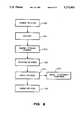
- FIG. 8shows a simplified block diagram of a rotation controller/encoder in accordance with a preferred embodiment of the present invention.
- FIG. 9shows a simplified block diagram of an acoustic imaging system which includes the ultrasound probe shown in FIG. 4, in accordance with a preferred embodiment of the present invention.
- FIG. 1shows, within a vessel 115, an ultrasound probe 101, residing within a catheter, in accordance with a first preferred embodiment of the present invention.
- Ultrasound probe 101includes a transducer 103 which generates ultrasound signals from electrical signals carried to ultrasound probe 101 through wire cable 113.
- Ultrasound signals from transducer 103, traveling in a direction 110,are reflected by a rotating acoustic reflector (mirror) 102, for example, in a radial direction 111 from ultrasound probe 101.
- mirrorrotating acoustic reflector
- the ultrasound signalspass through an acoustically transparent window 118 of ultrasound probe 101 and the catheter which encloses ultrasound probe 101.
- the ultrasound signalsare partially reflected by vessel walls 109 and tissue 108.
- the reflected portion of the ultrasound signalspropagate back to rotating mirror 102 and thereafter to transducer 103.
- Transducer 103generates electrical signals which are carried by wire cable 113 and which may be used to image a cross section of vessel 115.
- a coupling fluid 120is sealed inside probe 101 to enable transmission of ultrasound signals between transducer 103 and transparent window 118.
- transducer 103may be, for example, a piezoelectric ceramic resonator with a suitable backing which absorbs acoustic pulse signals which emanate from the piezoelectric ceramic resonator in a direction other than direction 110. Alternately, transducer 103 may be made by various other methods known in the art.
- rotating mirror 102is connected to a turbine 105.
- Turbine 105is located near a permeated tip 106 of ultrasound probe 101. Moving fluid 112 within vessel 115, flowing in a direction 107, flows through holes in permeated tip 106 and drives turbine 105.
- Turbine 105may be, for example, a multiple blade turbine constructed of molded plastic.
- a turbinemay be constructed using electroforming, extrusion, or other micromachining techniques known in the art.
- a rotation controller/encoder 104stores any excess energy produced by turbine 105, controls rotation of rotating mirror 102, and encodes the angle of rotating mirror 102 into electrical signals which are carried by wire cable 113. The electrical signals are used to time ultrasonic bursts generated by transducer 103.
- rotation controller/encoder 104may be simplified by placing a thin highly acoustically reflective strip as a marker on acoustically transparent window 118 of ultrasound probe 101.
- the acoustic reflection from the acoustically reflective stripis encoded within the electrical signals generated by transducer 103, and transported by wire cable 113.
- the electrical signal resulting from the acoustic reflections from the reflective stripserves as a marker, indicating when rotating mirror 102 reflects ultrasound bursts through the portion of acoustically transparent window 118 where the acoustic reflective strip resides.
- the resulting mark within the electrical signalis used to calculate the angular speed from the frequency of rotation of rotating mirror 102. From this the orientation of rotating mirror 102 within ultrasound probe 101 with respect to time is simply derived, as is clearly understood by those skilled in the art.
- ultrasound probe 101is perfectly adequate for applications where there is sufficient fluid flow to drive turbine 105.
- a vessel with a fluid flow of 50 centimeters per secondpresents an adequate environment for the use of ultrasound probe 101 with a turbine of three millimeters in diameter.
- an alternate embodiment of the present inventionshould be used.
- FIG. 2shows, within a vessel 215, an ultrasound probe 201, residing within a catheter, in accordance with a second preferred embodiment of the present invention.
- Ultrasound probe 201includes a transducer 203 which generates ultrasound signals from electrical signals carried to ultrasound probe 201 through wire cable 213.
- Ultrasound signals from transducer 203, traveling in a direction 210,are reflected by a rotating acoustic reflector (mirror) 202, for example, in a radial direction 211 from ultrasound probe 201.
- mirrorrotating acoustic reflector
- the ultrasound signalspass through an acoustically transparent window 218 of ultrasound probe 201.
- the ultrasound signalsare partially reflected by vessel walls 209 and tissue 208.
- the reflected portion of the ultrasound signalsare reflected back to transducer 203 by rotating mirror 202.
- Transducer 203generates electrical signals which are carried by wire cable 213 and which may be used to image a cross section of vessel 215.
- a coupling fluid 22is sealed inside probe 201 to enable transmission of ultrasound signals between transducer 203 and transparent window 218.
- Rotating mirror 202is connected to a turbine 205.
- Turbine 205is driven by vibrating fluid, for example air, supplied from a tube 216.
- the fluid vibrationsare represented by arrows 217.
- Turbine 205is excited by the vibrations of the fluid but is enabled to turn in only one direction.
- a mechanical ratchet within a rotation controller/encoder 204permits turbine 205 to step with a small fixed angle each time the pressure of the fluid is high enough to drive turbine 205 to rotate in the enabled direction.
- the stepping frequency of turbine 205equals the vibration frequency of the driving fluid.
- the angle of rotation of rotating mirror 202can be obtained by counting the number of elapsed cycles of air vibration after a "home" angle has been detected by a simple encoder within rotation controller/encoder 204. Further, as discussed above, a thin highly acoustically reflective strip can be placed as a marker on acoustically transparent window 218 of ultrasound probe 201. The electrical signal resulting from the acoustic reflections from the reflective strip serves as a marker, indicating when rotating mirror 202 reflects ultrasound bursts through the portion of acoustically transparent window 218 where the acoustic reflective strip resides.
- FIG. 3shows, within a vessel 315, an ultrasound probe 301, residing within a catheter, in accordance with a third preferred embodiment of the present invention.
- Ultrasound probe 301includes a transducer 303 which generates ultrasound signals from electrical signals carried to ultrasound probe 301 through wire cable 313.
- Ultrasound signals from transducer 303, traveling in a direction 310,are reflected by a rotating acoustic reflector (mirror) 302, for example, in a radial direction 311 from ultrasound probe 301.
- mirrorrotating acoustic reflector
- the ultrasound signalspass through an acoustically transparent window 318 of ultrasound probe 301.
- the ultrasound signalsare partially reflected by vessel walls 309 and tissue 308.
- the reflected portion of the ultrasound signalsare reflected back to transducer 303 by rotating mirror 302.
- Transducer 303generates electrical signals which are carried by wire cable 313 and which may be used to image a cross section of vessel 315.
- a coupling fluid 320is sealed inside probe 301 to enable transmission of ultrasound signals between transducer 303 and transparent window 318.
- Rotating mirror 302is connected to a turbine 305.
- Turbine 305is driven by vibrating fluid, for example air.
- a stack of piezoelectric transducers 316 enclosed in a chamberis used to produce vibrations.
- the fluid vibrationsare represented by arrows 317.
- Turbine 305is excited by the vibrating fluid but is enabled to turn in only one direction.
- a mechanical ratchet within a rotation controller/encoder 304permits turbine 305 to step with a small fixed angle each time the pressure of the fluid is high enough to drive turbine 305 to rotate in the enabled direction.
- the stepping frequency of turbine 305equals the vibration frequency of the driving fluid.
- Piezoelectric transducer 316is powered and controlled by electrical signals transported to ultrasound probe 301 through wire cable 313.
- the angle of rotation of rotating mirror 302can be obtained by counting the number of elapsed cycles of air vibration after a "home" angle has been detected by a simple encoder within rotation controller/encoder 304.
- a thin highly acoustically reflective stripcan be placed as a marker on acoustically transparent window 318.
- the electrical signal resulting from the acoustic reflections from the reflective stripserves as a marker, indicating when rotating mirror 302 reflects ultrasound bursts through the portion of acoustically transparent window 318 where the acoustic reflective strip resides.
- piezoelectric transducer 316allows for the generation of a higher vibration frequency than the design shown in FIG. 2, allowing for a faster stepping speed.
- the blades of turbine 305are designed to match the wave length of standing acoustic waves generated by piezoelectric transducer 316, precise stepping of turbine 305 can be accomplished without utilizing a mechanical ratchet within rotation controller/encoder 304.
- the turbine enclosureis filled with a fluid capable of supporting a standing wave. The spacing of the turbine blades are matched to the wavelength of the standing wave so that the blades will advance by one wavelength distance during each period of the standing wave, without using a mechanical ratchet to control the step size.
- FIG. 4shows, within a vessel 415, an ultrasound probe 401, residing within a catheter, in accordance with a fourth preferred embodiment of the present invention.
- Ultrasound probe 401includes a transducer 403 which generates ultrasound signals from electrical signals carried to ultrasound probe 401 through wire cable 413.
- Ultrasound signals from transducer 403, traveling in a direction 410,are reflected by a rotating acoustic reflector (mirror) 402, for example, in a radial direction 411 from ultrasound probe 401.
- mirrorrotating acoustic reflector
- the ultrasound signalspass through an acoustically transparent window 418 of ultrasound probe 401.
- the ultrasound signalsare partially reflected by vessel walls 409 and tissue 408.
- the reflected portion of the ultrasound signalsare reflected back to transducer 403 by rotating mirror 402.
- Transducer 403generates electrical signals which are carried by wire cable 413 and which may be used to image a cross section of vessel 415.
- a coupling fluid 420is sealed inside probe 401 to enable transmission of ultrasound signals between transducer 403 and transparent window 418.
- Rotating mirror 402is connected to a turbine 405.
- Turbine 405is driven by fluid, for example air, supplied from an inflow tube 416.
- the fluidexits ultrasound probe 401 through an outflow tube 417.
- a continuous fluid flowwill cause turbine 405 to rotate smoothly, without stepping.
- pulsating fluid flowcan be used to step the rotation of turbine 405.
- a rotation controller/encoder 404stores any excess energy produced by turbine 405, controls rotation of rotating mirror 402, and encodes the angle of rotating mirror 402 into electrical signals which are carried by wire cable 413.
- the design of the rotation controller/encoder 404may be simplified by placing a thin highly acoustically reflective strip as a marker on acoustically transparent window 418.
- the acoustic reflection from the acoustically reflective stripis encoded within the electrical signals generated by transducer 403, transported by wire cable 413.
- the electrical signal resulting from the acoustic reflections from the reflective stripserves as a marker, indicating when rotating mirror 402 reflects ultrasound bursts through the portion of acoustically transparent window 418 where the acoustic reflective strip resides.
- the resulting mark within the electrical signalis used to calculate the frequency of rotation and the angular speed of rotating mirror 402.
- the flow of fluid through inflow tube 416 and outflow tube 417may then be varied until turbine 405 rotates at the desired speed.
- FIG. 5shows, within a vessel 515, an ultrasound probe 501, residing within a catheter, in accordance with a fifth preferred embodiment of the present invention.
- Ultrasound probe 501includes a rotating transducer 503 which generates ultrasound signals from electrical signals carried to ultrasound probe 501 through wire cable 513. Ultrasound signals from rotating transducer 503 travel, for example, in a radial direction 511 from ultrasound probe 501.
- the ultrasound signalspass through an acoustically transparent window 518 of ultrasound probe 501.
- the ultrasound signalsare partially reflected by vessel walls 509 and tissue 508.
- the reflected portion of the ultrasound signalsare reflected back to rotating transducer 503.
- Rotating transducer 503generates electrical signals which are carried by wire cable 513 and which may be used to image a cross section of vessel 515.
- a coupling fluid 520is sealed inside probe 501 to enable transmission of ultrasound signals between transducer 503 and transparent window 518.
- Rotating transducer 503is connected to a turbine 505.
- Turbine 505is driven by fluid, for example air, supplied from an inflow tube 516.
- the fluidexits ultrasound probe 501 through an outflow tube 517.
- a continuous fluid flowwill cause turbine 505 to rotate smoothly, without stepping.
- pulsating fluid flowcan be used to step the rotation of turbine 505.
- a rotation controller/encoder 504stores any excess energy produced by turbine 505, controls rotation of rotating transducer 503, and encodes the angle of rotating transducer 503 into electrical signals which are carried by wire cable 513.
- the design of the rotation controller/encoder 504may be simplified by placing a thin highly acoustically reflective strip as a marker on acoustically transparent window 518.
- the acoustic reflection from the acoustically reflective stripis encoded within the electrical signals generated by rotating transducer 503, transported by wire cable 513.
- the electrical signal resulting from the acoustic reflections from the reflective stripserves as a marker, indicating when rotating transducer 503 transmits ultrasound bursts through the portion of acoustically transparent window 518 where the acoustic reflective strip resides.
- the resulting mark within the electrical signalis used to calculate the frequency of rotation and the angular speed of rotating transducer 503.
- the flow of fluid through inflow tube 516 and outflow tube 517may then be varied until turbine 505 rotates at the desired angular speed.
- FIG. 6shows, within a vessel 615, an ultrasound probe 601, residing within a catheter, in accordance with a sixth preferred embodiment of the present invention.
- Ultrasound probe 601receives ultrasound signals via an acoustic waveguide 613.
- the ultrasound signalswhen received by ultrasound probe 601, travel in a direction 610 and are reflected by a rotating acoustic reflector (mirror) 602, for example, in a radial direction 611 from ultrasound probe 601.
- mirrorrotating acoustic reflector
- the ultrasound signalspass through an acoustically transparent window 618 of ultrasound probe 601.
- the ultrasound signalsare partially reflected by vessel walls 609 and tissue 608.
- the reflected portion of the ultrasound signalsare reflected back to acoustic waveguide 613 by rotating mirror 602.
- Acoustic waveguide 613returns the ultrasound signals to a transducer at the other end of waveguide 613.
- the electrical signals from the transducermay be used to image a cross section of vessel 615.
- a coupling fluid 620is sealed inside probe 601 to enable transmission of ultrasound signals between waveguide 613 and transparent window 618.
- Rotating mirror 602is connected to a turbine 605.
- Turbine 605is driven by vibrating fluid, for example air, supplied from a tube 616.
- the fluid vibrationsare represented by arrows 617.
- Turbine 605is excited by the vibrations of the fluid but is enabled to turn in only on direction.
- a mechanical ratchet within a rotation controller/encoder 604permits turbine 605 to step with a small fixed angle each time the pressure of the fluid is high enough to drive turbine 605 to rotate in the enabled direction.
- the stepping frequency of turbine 605equals the vibration frequency of the driving fluid.
- the angle of rotation of rotating mirror 602can be obtained by counting the number of elapsed cycles of air vibration after a "home" angle has been detected by a simple encoder within rotation controller/encoder 604. Further, as discussed above, a thin highly acoustically reflective strip can be placed as a marker on acoustically transparent window 618 of ultrasound probe 601. The electrical signal resulting from the acoustic reflections from the reflective strip serves as a marker, indicating when rotating mirror 602 reflects ultrasound bursts through the portion of acoustically transparent window 618 where the acoustic reflective strip resides.
- FIG. 7shows, within a vessel 715, an ultrasound probe 701, residing within a catheter, in accordance with a seventh preferred embodiment of the present invention.
- Ultrasound probe 701includes a transducer 703 which generates ultrasound signals from electrical signals carried to ultrasound probe 701 through wire cable 713.
- Ultrasound signals from transducer 703, traveling in a direction 710,are reflected by a rotating acoustic reflector (mirror) 702, for example, in a radial direction 711 from ultrasound probe 701.
- mirrorrotating acoustic reflector
- the ultrasound signalspass through an acoustically transparent window 718 of ultrasound probe 701.
- the ultrasound signalsare partially reflected by vessel walls 709 and tissue 708.
- the reflected portion of the ultrasound signalsare reflected back to transducer 703 by rotating mirror 702.
- Transducer 703generates electrical signals which are carried by wire cable 713 and which may be used to image a cross section of vessel 715.
- a coupling fluid 720is sealed inside probe 701 to enable transmission of ultrasound signals between transducer 703 and transparent window 718.
- Rotating mirror 702is connected to a turbine 705.
- Turbine 705is driven by vapor bubbles generated from electrical heaters 716.
- the explosive formation of a vapor bubble within the drive fluid 717 due to the application of an electrical pulse to a resistor (electrical heater) within drive fluid 717transfers kinetic energy to the turbine.
- the electrical pulsevery quickly heats the resistor to near the superheat limit of the drive fluid 717.
- Such a formation of vapor bubblesis discussed in U.S. Pat. No. 4,490,728 issued to Vaught et al. on Dec. 25, 1984 for a Thermal Ink Jet Printer, the subject matter of which patent is hereby incorporated by reference.
- Electrical heater 716is powered and controlled by electrical signals transported to ultrasound probe 701 through wire cable 713.
- the use of electrical heater 716allows for a faster stepping speed than the design shown in FIG. 2.
- the angle of rotation of rotating mirror 702can be obtained by counting the number of electrical pulses after a "home" angle has been detected by a simple encoder within rotation controller/encoder 704.
- a thin highly acoustically reflective stripcan be placed as a marker on acoustically transparent window 718.
- the electrical signal resulting from the acoustic reflections from the reflective stripserves as a marker, indicating when rotating mirror 702 reflects ultrasound bursts through the portion of acoustically transparent window 718 where the acoustic reflective strip resides.
- FIG. 8shows a simplified block diagram of a rotation controller/encoder which may be used in any of the previously described ultrasound probes.
- Turbine rotation 800is controlled by a ratchet 801.
- An energy storage spring 802stores excess energy generated by the turbine.
- a rotation metering block 803meters rotation.
- An angle encoder 804generates a signal 805 to be returned to a scanner mainframe so that the angular speed of mirror rotation 806 can be obtained.
- FIG. 9shows a simplified block diagram of an acoustic imaging system which includes ultrasound probe 401.
- Fluid control unit 903controls fluid flow through inflow tube 416 and outflow tube 417.
- a scanner mainframe 901generates electrical signals placed on wire cable 413, and processes electrical signals which ultrasound probe 401 places on wire cable 413.
- the scanner mainframe 901calculates the angular speed from the frequency of rotation of rotating mirror 402 by decoding the acoustic reflection from the acoustically reflective strip. Scanner mainframe then varies a control signal on control lines 902, to direct fluid control unit 903 to increase or decrease fluid flow so that turbine 405 will rotate at a desired angular speed.
Landscapes
- Life Sciences & Earth Sciences (AREA)
- Health & Medical Sciences (AREA)
- Biomedical Technology (AREA)
- Biophysics (AREA)
- Nuclear Medicine, Radiotherapy & Molecular Imaging (AREA)
- Pathology (AREA)
- Radiology & Medical Imaging (AREA)
- Engineering & Computer Science (AREA)
- Physics & Mathematics (AREA)
- Heart & Thoracic Surgery (AREA)
- Medical Informatics (AREA)
- Molecular Biology (AREA)
- Surgery (AREA)
- Animal Behavior & Ethology (AREA)
- General Health & Medical Sciences (AREA)
- Public Health (AREA)
- Veterinary Medicine (AREA)
- Ultra Sonic Daignosis Equipment (AREA)
Abstract
Description
Claims (30)
Priority Applications (1)
| Application Number | Priority Date | Filing Date | Title |
|---|---|---|---|
| US07/892,451US5271402A (en) | 1992-06-02 | 1992-06-02 | Turbine drive mechanism for steering ultrasound signals |
Applications Claiming Priority (1)
| Application Number | Priority Date | Filing Date | Title |
|---|---|---|---|
| US07/892,451US5271402A (en) | 1992-06-02 | 1992-06-02 | Turbine drive mechanism for steering ultrasound signals |
Publications (1)
| Publication Number | Publication Date |
|---|---|
| US5271402Atrue US5271402A (en) | 1993-12-21 |
Family
ID=25399971
Family Applications (1)
| Application Number | Title | Priority Date | Filing Date |
|---|---|---|---|
| US07/892,451Expired - Fee RelatedUS5271402A (en) | 1992-06-02 | 1992-06-02 | Turbine drive mechanism for steering ultrasound signals |
Country Status (1)
| Country | Link |
|---|---|
| US (1) | US5271402A (en) |
Cited By (63)
| Publication number | Priority date | Publication date | Assignee | Title |
|---|---|---|---|---|
| US5406951A (en)* | 1993-10-15 | 1995-04-18 | Ten Hoff; Harm | Intra-luminal ultrasonic instrument |
| US5485845A (en)* | 1995-05-04 | 1996-01-23 | Hewlett Packard Company | Rotary encoder for intravascular ultrasound catheter |
| US5507294A (en)* | 1995-01-17 | 1996-04-16 | Hewlett Packard Company | Ultrasound diagnostic probe having non-rotating acoustic imaging waveguide |
| US5509418A (en)* | 1995-01-17 | 1996-04-23 | Hewlett-Packard Co. | Ultrasound diagnostic probe having acoustically driven turbin |
| US5606975A (en)* | 1994-09-19 | 1997-03-04 | The Board Of Trustees Of The Leland Stanford Junior University | Forward viewing ultrasonic imaging catheter |
| DE19625649A1 (en)* | 1995-09-25 | 1997-03-27 | Hewlett Packard Co | Focusing ultrasound beam onto target region of object esp. for intravascular ultrasound imaging |
| US5635784A (en)* | 1995-02-13 | 1997-06-03 | Seale; Joseph B. | Bearingless ultrasound-sweep rotor |
| US5647367A (en)* | 1996-05-31 | 1997-07-15 | Hewlett-Packard Company | Scanning ultrasonic probe with locally-driven sweeping ultrasonic source |
| WO1997034288A1 (en)* | 1996-03-13 | 1997-09-18 | Hewlett-Packard Company | Direct contact scanner and related method |
| DE19613242A1 (en)* | 1996-04-02 | 1997-10-09 | Siemens Ag | Mechanical sector scanner esp. for acoustic therapy appts. with ultrasound location |
| DE19613239A1 (en)* | 1996-04-02 | 1997-10-16 | Siemens Ag | Mechanical sector scanner for ultrasound diagnostic appts. |
| DE19709241A1 (en)* | 1996-05-31 | 1997-12-04 | Hewlett Packard Co | Scanning ultrasound probe with locally driven wobble ultrasound source |
| US5699806A (en)* | 1996-10-01 | 1997-12-23 | Hewlett-Packard Company | Ultrasound system with nonuniform rotation corrector |
| US5701901A (en)* | 1996-11-26 | 1997-12-30 | Hewlett Packard Company | Ultrasonic probe with back and forth sweeping ultrasonic source |
| US5779643A (en)* | 1996-11-26 | 1998-07-14 | Hewlett-Packard Company | Imaging guidewire with back and forth sweeping ultrasonic source |
| WO1998046119A1 (en)* | 1997-04-11 | 1998-10-22 | Transvascular, Inc. | Catheters and related devices for forming passageways between blood vessels or other anatomical structures |
| US5989191A (en)* | 1998-06-19 | 1999-11-23 | Hewlettt-Packard Company | Using doppler techniques to measure non-uniform rotation of an ultrasound transducer |
| US6019726A (en)* | 1998-06-10 | 2000-02-01 | Hewlett-Packard Company | Catheter having probes for correcting for non-uniform rotation of a transducer located within the catheter |
| US6159225A (en)* | 1995-10-13 | 2000-12-12 | Transvascular, Inc. | Device for interstitial transvascular intervention and revascularization |
| US20050203416A1 (en)* | 2004-03-10 | 2005-09-15 | Angelsen Bjorn A. | Extended, ultrasound real time 2D imaging probe for insertion into the body |
| US20050203396A1 (en)* | 2004-03-09 | 2005-09-15 | Angelsen Bjorn A. | Extended, ultrasound real time 3D image probe for insertion into the body |
| US20060241493A1 (en)* | 2003-04-28 | 2006-10-26 | Feldman Marc D | Catheter imaging probe and method |
| US20070016063A1 (en)* | 2005-05-04 | 2007-01-18 | Byong-Ho Park | Miniature actuator mechanism for intravascular imaging |
| WO2007032682A1 (en)* | 2005-09-15 | 2007-03-22 | Angelsen Bjoern A J | Extended, ultrasound real time imaging probe for insertion into the body |
| US20070106155A1 (en)* | 2005-10-31 | 2007-05-10 | Novelis, Inc. | System and method for reducing angular geometric distortion in an imaging device |
| US20070161893A1 (en)* | 2003-04-28 | 2007-07-12 | Board Of Regents, The University Of Texas System | Rotating optical catheter tip for optical coherence tomography |
| US20070167821A1 (en)* | 2005-11-30 | 2007-07-19 | Warren Lee | Rotatable transducer array for volumetric ultrasound |
| US20070167804A1 (en)* | 2002-09-18 | 2007-07-19 | Byong-Ho Park | Tubular compliant mechanisms for ultrasonic imaging systems and intravascular interventional devices |
| US20070232913A1 (en)* | 2006-01-13 | 2007-10-04 | Mirabilis Medica Inc. | Methods and apparatus for the treatment of menometrorrhagia, endometrial pathology, and cervical neoplasia using high intensity focused ultrasound energy |
| US20070250000A1 (en)* | 2006-03-30 | 2007-10-25 | Novelis, Inc. | Method and system for imaging, diagnosing, and/or treating an area of interest in a patient's body |
| US20070268287A1 (en)* | 2006-05-22 | 2007-11-22 | Magnin Paul A | Apparatus and method for rendering for display forward-looking image data |
| US20080200801A1 (en)* | 2007-02-21 | 2008-08-21 | Douglas Glenn Wildes | Mapping Movement of a Movable Transducer |
| US20080287801A1 (en)* | 2006-08-14 | 2008-11-20 | Novelis, Inc. | Imaging device, imaging system, and methods of imaging |
| US20090036773A1 (en)* | 2007-07-31 | 2009-02-05 | Mirabilis Medica Inc. | Methods and apparatus for engagement and coupling of an intracavitory imaging and high intensity focused ultrasound probe |
| US20090088636A1 (en)* | 2006-01-13 | 2009-04-02 | Mirabilis Medica, Inc. | Apparatus for delivering high intensity focused ultrasound energy to a treatment site internal to a patient's body |
| US20090118725A1 (en)* | 2007-11-07 | 2009-05-07 | Mirabilis Medica, Inc. | Hemostatic tissue tunnel generator for inserting treatment apparatus into tissue of a patient |
| US20090118729A1 (en)* | 2007-11-07 | 2009-05-07 | Mirabilis Medica Inc. | Hemostatic spark erosion tissue tunnel generator with integral treatment providing variable volumetric necrotization of tissue |
| US20090247879A1 (en)* | 2004-03-09 | 2009-10-01 | Angelsen Bjorn A J | Extended ultrasound imaging probe for insertion into the body |
| US20100036291A1 (en)* | 2008-08-06 | 2010-02-11 | Mirabilis Medica Inc. | Optimization and feedback control of hifu power deposition through the frequency analysis of backscattered hifu signals |
| US20100036292A1 (en)* | 2008-08-06 | 2010-02-11 | Mirabilis Medica Inc. | Optimization and feedback control of hifu power deposition through the analysis of detected signal characteristics |
| US20100123903A1 (en)* | 2008-11-19 | 2010-05-20 | Industrial Technology Research Institute | Optical scanning probe |
| US20100160788A1 (en)* | 2008-12-19 | 2010-06-24 | Volcano Corporation | Rotational intravascular ultrasound probe and method of manufacturing the same |
| US20100168570A1 (en)* | 2008-12-31 | 2010-07-01 | Sliwa John W | Methods and Apparatus for Utilizing Impeller-Based Rotationally-Scanning Catheters |
| US20100210976A1 (en)* | 2008-10-03 | 2010-08-19 | Mirabilis Medica, Inc. | Method and apparatus for treating tissues with hifu |
| US20100241005A1 (en)* | 2008-10-03 | 2010-09-23 | Mirabilis Medica, Inc. | Office-based system for treating uterine fibroids or other tissues with hifu |
| US20100249599A1 (en)* | 2009-03-31 | 2010-09-30 | Boston Scientific Scimed, Inc. | Systems and methods for making and using an imaging core of an intravascular ultrasound imaging system |
| US20100249604A1 (en)* | 2009-03-31 | 2010-09-30 | Boston Scientific Corporation | Systems and methods for making and using a motor distally-positioned within a catheter of an intravascular ultrasound imaging system |
| US20100249603A1 (en)* | 2009-03-31 | 2010-09-30 | Boston Scientific Scimed, Inc. | Systems and methods for making and using a motor distally-positioned within a catheter of an intravascular ultrasound imaging system |
| US20110004095A1 (en)* | 2004-12-23 | 2011-01-06 | Michael Maschke | Intravenous Pacemaker Electrode |
| US20110071401A1 (en)* | 2009-09-24 | 2011-03-24 | Boston Scientific Scimed, Inc. | Systems and methods for making and using a stepper motor for an intravascular ultrasound imaging system |
| US20110071400A1 (en)* | 2009-09-23 | 2011-03-24 | Boston Scientific Scimed, Inc. | Systems and methods for making and using intravascular ultrasound imaging systems with sealed imaging cores |
| US20110112409A1 (en)* | 2003-04-28 | 2011-05-12 | Board Of Regents, The University Of Texas System | Rotating catheter probe using a light-drive apparatus |
| US8197413B2 (en) | 2008-06-06 | 2012-06-12 | Boston Scientific Scimed, Inc. | Transducers, devices and systems containing the transducers, and methods of manufacture |
| US8632467B2 (en) | 2011-10-12 | 2014-01-21 | Volcano Corporation | Rotational shape-memory actuators and associated devices, systems, and methods |
| US8961425B2 (en) | 2009-03-11 | 2015-02-24 | Volcano Corporation | Rotational intravascular ultrasound probe with an active spinning element |
| JP2015518400A (en)* | 2012-04-23 | 2015-07-02 | セント・ジュード・メディカル・インコーポレーテッドSt Jude Medical Incorporated | Ultrasound lesion feedback, non-pop monitoring, and force detection |
| US20150305716A1 (en)* | 2014-04-28 | 2015-10-29 | Koninklijke Philips N.V | Ultrasound Transducer Array Apparatus and Method of Imaging Using Transducer Arrays |
| US20160015362A1 (en)* | 2014-07-16 | 2016-01-21 | Volcano Corporation | Intravascular devices, systems, and methods having motors |
| US20160351783A1 (en)* | 2014-01-29 | 2016-12-01 | Sogang University Research Foundation | Method for producing intravascular ultrasonic transducers and structure thereof |
| JP2018149380A (en)* | 2007-01-19 | 2018-09-27 | サニーブルック・ヘルス・サイエンシズ・センター | Scanning mechanisms for imaging probe |
| US20220218527A1 (en)* | 2006-08-07 | 2022-07-14 | Carl Zeiss Meditec Ag | Apparatus for individual therapy planning and positionally accurate modification of an optical element |
| US11744551B2 (en) | 2017-05-05 | 2023-09-05 | Biim Ultrasound As | Hand held ultrasound probe |
| WO2024100558A1 (en)* | 2022-11-11 | 2024-05-16 | Otsuka Medical Devices Co., Ltd. | Rotating cylinder |
Citations (11)
| Publication number | Priority date | Publication date | Assignee | Title |
|---|---|---|---|---|
| US4176662A (en)* | 1977-06-17 | 1979-12-04 | The United States Of America As Represented By The Administrator Of The National Aeronautics And Space Administration | Apparatus for endoscopic examination |
| US4432371A (en)* | 1982-06-10 | 1984-02-21 | Advanced Technology Laboratories, Inc. | Ultrasound scanhead |
| US4490728A (en)* | 1981-08-14 | 1984-12-25 | Hewlett-Packard Company | Thermal ink jet printer |
| EP0139574A2 (en)* | 1983-09-29 | 1985-05-02 | Bruno Denis Lucien Fornage | Ultrasonic probe for body tracts |
| US4572201A (en)* | 1983-10-11 | 1986-02-25 | Hitachi, Ltd. | Probe for intraluminal ultrasonic scanner |
| US4748985A (en)* | 1985-05-10 | 1988-06-07 | Olympus Optical Co., Ltd. | Ultrasonic imaging apparatus having circulating cooling liquid for cooling ultrasonic transducers thereof |
| US4779624A (en)* | 1986-05-21 | 1988-10-25 | Olympus Optical Co., Ltd. | Ultrasonic endoscope |
| US4794931A (en)* | 1986-02-28 | 1989-01-03 | Cardiovascular Imaging Systems, Inc. | Catheter apparatus, system and method for intravascular two-dimensional ultrasonography |
| US5000185A (en)* | 1986-02-28 | 1991-03-19 | Cardiovascular Imaging Systems, Inc. | Method for intravascular two-dimensional ultrasonography and recanalization |
| US5046503A (en)* | 1989-04-26 | 1991-09-10 | Advanced Cardiovascular Systems, Inc. | Angioplasty autoperfusion catheter flow measurement method and apparatus |
| US5199437A (en)* | 1991-09-09 | 1993-04-06 | Sensor Electronics, Inc. | Ultrasonic imager |
- 1992
- 1992-06-02USUS07/892,451patent/US5271402A/ennot_activeExpired - Fee Related
Patent Citations (11)
| Publication number | Priority date | Publication date | Assignee | Title |
|---|---|---|---|---|
| US4176662A (en)* | 1977-06-17 | 1979-12-04 | The United States Of America As Represented By The Administrator Of The National Aeronautics And Space Administration | Apparatus for endoscopic examination |
| US4490728A (en)* | 1981-08-14 | 1984-12-25 | Hewlett-Packard Company | Thermal ink jet printer |
| US4432371A (en)* | 1982-06-10 | 1984-02-21 | Advanced Technology Laboratories, Inc. | Ultrasound scanhead |
| EP0139574A2 (en)* | 1983-09-29 | 1985-05-02 | Bruno Denis Lucien Fornage | Ultrasonic probe for body tracts |
| US4572201A (en)* | 1983-10-11 | 1986-02-25 | Hitachi, Ltd. | Probe for intraluminal ultrasonic scanner |
| US4748985A (en)* | 1985-05-10 | 1988-06-07 | Olympus Optical Co., Ltd. | Ultrasonic imaging apparatus having circulating cooling liquid for cooling ultrasonic transducers thereof |
| US4794931A (en)* | 1986-02-28 | 1989-01-03 | Cardiovascular Imaging Systems, Inc. | Catheter apparatus, system and method for intravascular two-dimensional ultrasonography |
| US5000185A (en)* | 1986-02-28 | 1991-03-19 | Cardiovascular Imaging Systems, Inc. | Method for intravascular two-dimensional ultrasonography and recanalization |
| US4779624A (en)* | 1986-05-21 | 1988-10-25 | Olympus Optical Co., Ltd. | Ultrasonic endoscope |
| US5046503A (en)* | 1989-04-26 | 1991-09-10 | Advanced Cardiovascular Systems, Inc. | Angioplasty autoperfusion catheter flow measurement method and apparatus |
| US5199437A (en)* | 1991-09-09 | 1993-04-06 | Sensor Electronics, Inc. | Ultrasonic imager |
Cited By (120)
| Publication number | Priority date | Publication date | Assignee | Title |
|---|---|---|---|---|
| US5406951A (en)* | 1993-10-15 | 1995-04-18 | Ten Hoff; Harm | Intra-luminal ultrasonic instrument |
| US5606975A (en)* | 1994-09-19 | 1997-03-04 | The Board Of Trustees Of The Leland Stanford Junior University | Forward viewing ultrasonic imaging catheter |
| US5507294A (en)* | 1995-01-17 | 1996-04-16 | Hewlett Packard Company | Ultrasound diagnostic probe having non-rotating acoustic imaging waveguide |
| US5509418A (en)* | 1995-01-17 | 1996-04-23 | Hewlett-Packard Co. | Ultrasound diagnostic probe having acoustically driven turbin |
| EP0722693A3 (en)* | 1995-01-17 | 1997-06-25 | Hewlett Packard Co | Ultrasound diagnostic probe having non-rotating acoustic imaging waveguide |
| US5635784A (en)* | 1995-02-13 | 1997-06-03 | Seale; Joseph B. | Bearingless ultrasound-sweep rotor |
| US5485845A (en)* | 1995-05-04 | 1996-01-23 | Hewlett Packard Company | Rotary encoder for intravascular ultrasound catheter |
| DE19625649A1 (en)* | 1995-09-25 | 1997-03-27 | Hewlett Packard Co | Focusing ultrasound beam onto target region of object esp. for intravascular ultrasound imaging |
| US5640961A (en)* | 1995-09-25 | 1997-06-24 | Hewlett-Packard Company | Device with aspherical compensation for focusing ultrasound |
| US6159225A (en)* | 1995-10-13 | 2000-12-12 | Transvascular, Inc. | Device for interstitial transvascular intervention and revascularization |
| WO1997034288A1 (en)* | 1996-03-13 | 1997-09-18 | Hewlett-Packard Company | Direct contact scanner and related method |
| US6190323B1 (en)* | 1996-03-13 | 2001-02-20 | Agielnt Technologies | Direct contact scanner and related method |
| DE19613242A1 (en)* | 1996-04-02 | 1997-10-09 | Siemens Ag | Mechanical sector scanner esp. for acoustic therapy appts. with ultrasound location |
| DE19613239A1 (en)* | 1996-04-02 | 1997-10-16 | Siemens Ag | Mechanical sector scanner for ultrasound diagnostic appts. |
| DE19709241A1 (en)* | 1996-05-31 | 1997-12-04 | Hewlett Packard Co | Scanning ultrasound probe with locally driven wobble ultrasound source |
| US5647367A (en)* | 1996-05-31 | 1997-07-15 | Hewlett-Packard Company | Scanning ultrasonic probe with locally-driven sweeping ultrasonic source |
| US5699806A (en)* | 1996-10-01 | 1997-12-23 | Hewlett-Packard Company | Ultrasound system with nonuniform rotation corrector |
| US5701901A (en)* | 1996-11-26 | 1997-12-30 | Hewlett Packard Company | Ultrasonic probe with back and forth sweeping ultrasonic source |
| US5779643A (en)* | 1996-11-26 | 1998-07-14 | Hewlett-Packard Company | Imaging guidewire with back and forth sweeping ultrasonic source |
| WO1998046119A1 (en)* | 1997-04-11 | 1998-10-22 | Transvascular, Inc. | Catheters and related devices for forming passageways between blood vessels or other anatomical structures |
| US6019726A (en)* | 1998-06-10 | 2000-02-01 | Hewlett-Packard Company | Catheter having probes for correcting for non-uniform rotation of a transducer located within the catheter |
| US5989191A (en)* | 1998-06-19 | 1999-11-23 | Hewlettt-Packard Company | Using doppler techniques to measure non-uniform rotation of an ultrasound transducer |
| US20070167804A1 (en)* | 2002-09-18 | 2007-07-19 | Byong-Ho Park | Tubular compliant mechanisms for ultrasonic imaging systems and intravascular interventional devices |
| US7853316B2 (en)* | 2003-04-28 | 2010-12-14 | Board Of Regents, The University Of Texas System | Rotating optical catheter tip for optical coherence tomography |
| US20060241493A1 (en)* | 2003-04-28 | 2006-10-26 | Feldman Marc D | Catheter imaging probe and method |
| JP2006524553A (en)* | 2003-04-28 | 2006-11-02 | ボード オブ リージェンツ, ザ ユニバーシティ オブ テキサス システム | Catheter imaging probe and method |
| US8989849B2 (en) | 2003-04-28 | 2015-03-24 | Board Of Regents, The University Of Texas System | Rotating optical catheter tip for optical coherence tomography |
| US9591961B2 (en) | 2003-04-28 | 2017-03-14 | Board Of Regents, The University Of Texas System | Rotating catheter probe using a light-drive apparatus |
| US20110112409A1 (en)* | 2003-04-28 | 2011-05-12 | Board Of Regents, The University Of Texas System | Rotating catheter probe using a light-drive apparatus |
| US20110152771A1 (en)* | 2003-04-28 | 2011-06-23 | Board of Regents, The University of Texas Systsem | Rotating optical catheter tip for optical coherence tomography |
| US20070161893A1 (en)* | 2003-04-28 | 2007-07-12 | Board Of Regents, The University Of Texas System | Rotating optical catheter tip for optical coherence tomography |
| US20100168587A1 (en)* | 2003-04-28 | 2010-07-01 | Board Of Regents, The University Of Texas System | Catheter imaging probe and method |
| US8996099B2 (en)* | 2003-04-28 | 2015-03-31 | Board Of Regents, The University Of Texas System | Catheter imaging probe and method |
| US7711413B2 (en)* | 2003-04-28 | 2010-05-04 | Volcano Corporation | Catheter imaging probe and method |
| EP1620013A4 (en)* | 2003-04-28 | 2009-05-27 | Univ Texas | PROBE AND METHOD FOR CATHETER IMAGING |
| US8401610B2 (en) | 2003-04-28 | 2013-03-19 | Board Of Regents, The University Of Texas System | Rotating catheter probe using a light-drive apparatus |
| US20050203396A1 (en)* | 2004-03-09 | 2005-09-15 | Angelsen Bjorn A. | Extended, ultrasound real time 3D image probe for insertion into the body |
| US7699782B2 (en)* | 2004-03-09 | 2010-04-20 | Angelsen Bjoern A J | Extended, ultrasound real time 3D image probe for insertion into the body |
| US20090247879A1 (en)* | 2004-03-09 | 2009-10-01 | Angelsen Bjorn A J | Extended ultrasound imaging probe for insertion into the body |
| US20050203416A1 (en)* | 2004-03-10 | 2005-09-15 | Angelsen Bjorn A. | Extended, ultrasound real time 2D imaging probe for insertion into the body |
| US20110004095A1 (en)* | 2004-12-23 | 2011-01-06 | Michael Maschke | Intravenous Pacemaker Electrode |
| US7658715B2 (en)* | 2005-05-04 | 2010-02-09 | Fluid Medical | Miniature actuator mechanism for intravascular imaging |
| US20080287810A1 (en)* | 2005-05-04 | 2008-11-20 | Byong-Ho Park | Miniature actuator mechanism for intravascular optical imaging |
| EP2461180A1 (en)* | 2005-05-04 | 2012-06-06 | Volcano Corporation | Miniature actuator mechanism for intravascular imaging |
| US20100113938A1 (en)* | 2005-05-04 | 2010-05-06 | Fluid Medical | Miniature actuator mechanism for intravascular imaging |
| US8652050B2 (en) | 2005-05-04 | 2014-02-18 | Volcano Corporation | Miniature actuator mechanism for intravascular imaging |
| US20070016063A1 (en)* | 2005-05-04 | 2007-01-18 | Byong-Ho Park | Miniature actuator mechanism for intravascular imaging |
| WO2006119416A3 (en)* | 2005-05-04 | 2007-03-08 | Fluid Medical Inc | Miniature actuator mechanism for intravascular imaging |
| US8187193B2 (en) | 2005-05-04 | 2012-05-29 | Volcano Corporation | Miniature actuator mechanism for intravascular imaging |
| WO2007032682A1 (en)* | 2005-09-15 | 2007-03-22 | Angelsen Bjoern A J | Extended, ultrasound real time imaging probe for insertion into the body |
| EP1948021A4 (en)* | 2005-10-20 | 2009-12-02 | Univ Texas | OPTICAL ROTARY CATHETER POINTE FOR OPTICAL COHERENCE TOMOGRAPHY |
| US8047996B2 (en) | 2005-10-31 | 2011-11-01 | Volcano Corporation | System and method for reducing angular geometric distortion in an imaging device |
| US20070106155A1 (en)* | 2005-10-31 | 2007-05-10 | Novelis, Inc. | System and method for reducing angular geometric distortion in an imaging device |
| US8414496B2 (en) | 2005-10-31 | 2013-04-09 | Volcano Corporation | System and method for reducing angular geometric distortion in an imaging device |
| US20070167821A1 (en)* | 2005-11-30 | 2007-07-19 | Warren Lee | Rotatable transducer array for volumetric ultrasound |
| US8057391B2 (en) | 2006-01-13 | 2011-11-15 | Mirabilis Medica, Inc. | Apparatus for delivering high intensity focused ultrasound energy to a treatment site internal to a patient's body |
| US20070232913A1 (en)* | 2006-01-13 | 2007-10-04 | Mirabilis Medica Inc. | Methods and apparatus for the treatment of menometrorrhagia, endometrial pathology, and cervical neoplasia using high intensity focused ultrasound energy |
| US8277379B2 (en) | 2006-01-13 | 2012-10-02 | Mirabilis Medica Inc. | Methods and apparatus for the treatment of menometrorrhagia, endometrial pathology, and cervical neoplasia using high intensity focused ultrasound energy |
| US20090088636A1 (en)* | 2006-01-13 | 2009-04-02 | Mirabilis Medica, Inc. | Apparatus for delivering high intensity focused ultrasound energy to a treatment site internal to a patient's body |
| US10512446B2 (en) | 2006-03-30 | 2019-12-24 | Volcano Corporation | Method and system for imaging, diagnosing, and/or treating an area of interest in a patient's body |
| US7785286B2 (en) | 2006-03-30 | 2010-08-31 | Volcano Corporation | Method and system for imaging, diagnosing, and/or treating an area of interest in a patient's body |
| US20070250000A1 (en)* | 2006-03-30 | 2007-10-25 | Novelis, Inc. | Method and system for imaging, diagnosing, and/or treating an area of interest in a patient's body |
| US10039522B2 (en) | 2006-03-30 | 2018-08-07 | Volcano Corporation | Method and system for imaging, diagnosing, and/or treating an area of interest in a patient's body |
| US8491567B2 (en) | 2006-03-30 | 2013-07-23 | Volcano Corporation | Method and system for imaging, diagnosing, and/or treating an area of interest in a patient's body |
| WO2007139697A3 (en)* | 2006-05-22 | 2008-03-20 | Novelis Investments Canada | Apparatus and method for rendering for display forward-looking image data |
| US7612773B2 (en)* | 2006-05-22 | 2009-11-03 | Magnin Paul A | Apparatus and method for rendering for display forward-looking image data |
| US20070268287A1 (en)* | 2006-05-22 | 2007-11-22 | Magnin Paul A | Apparatus and method for rendering for display forward-looking image data |
| US12029685B2 (en)* | 2006-08-07 | 2024-07-09 | Carl Zeiss Meditec Ag | Apparatus for individual therapy planning and positionally accurate modification of an optical element |
| US20220218527A1 (en)* | 2006-08-07 | 2022-07-14 | Carl Zeiss Meditec Ag | Apparatus for individual therapy planning and positionally accurate modification of an optical element |
| US20080287801A1 (en)* | 2006-08-14 | 2008-11-20 | Novelis, Inc. | Imaging device, imaging system, and methods of imaging |
| JP2018149380A (en)* | 2007-01-19 | 2018-09-27 | サニーブルック・ヘルス・サイエンシズ・センター | Scanning mechanisms for imaging probe |
| US20080200801A1 (en)* | 2007-02-21 | 2008-08-21 | Douglas Glenn Wildes | Mapping Movement of a Movable Transducer |
| US20090036773A1 (en)* | 2007-07-31 | 2009-02-05 | Mirabilis Medica Inc. | Methods and apparatus for engagement and coupling of an intracavitory imaging and high intensity focused ultrasound probe |
| US8052604B2 (en)* | 2007-07-31 | 2011-11-08 | Mirabilis Medica Inc. | Methods and apparatus for engagement and coupling of an intracavitory imaging and high intensity focused ultrasound probe |
| US8187270B2 (en) | 2007-11-07 | 2012-05-29 | Mirabilis Medica Inc. | Hemostatic spark erosion tissue tunnel generator with integral treatment providing variable volumetric necrotization of tissue |
| US20090118729A1 (en)* | 2007-11-07 | 2009-05-07 | Mirabilis Medica Inc. | Hemostatic spark erosion tissue tunnel generator with integral treatment providing variable volumetric necrotization of tissue |
| US20090118725A1 (en)* | 2007-11-07 | 2009-05-07 | Mirabilis Medica, Inc. | Hemostatic tissue tunnel generator for inserting treatment apparatus into tissue of a patient |
| US8439907B2 (en) | 2007-11-07 | 2013-05-14 | Mirabilis Medica Inc. | Hemostatic tissue tunnel generator for inserting treatment apparatus into tissue of a patient |
| US8197413B2 (en) | 2008-06-06 | 2012-06-12 | Boston Scientific Scimed, Inc. | Transducers, devices and systems containing the transducers, and methods of manufacture |
| US20100036292A1 (en)* | 2008-08-06 | 2010-02-11 | Mirabilis Medica Inc. | Optimization and feedback control of hifu power deposition through the analysis of detected signal characteristics |
| US20100036291A1 (en)* | 2008-08-06 | 2010-02-11 | Mirabilis Medica Inc. | Optimization and feedback control of hifu power deposition through the frequency analysis of backscattered hifu signals |
| US8216161B2 (en) | 2008-08-06 | 2012-07-10 | Mirabilis Medica Inc. | Optimization and feedback control of HIFU power deposition through the frequency analysis of backscattered HIFU signals |
| US9248318B2 (en) | 2008-08-06 | 2016-02-02 | Mirabilis Medica Inc. | Optimization and feedback control of HIFU power deposition through the analysis of detected signal characteristics |
| US10226646B2 (en) | 2008-08-06 | 2019-03-12 | Mirabillis Medica, Inc. | Optimization and feedback control of HIFU power deposition through the analysis of detected signal characteristics |
| US20100241005A1 (en)* | 2008-10-03 | 2010-09-23 | Mirabilis Medica, Inc. | Office-based system for treating uterine fibroids or other tissues with hifu |
| US9770605B2 (en) | 2008-10-03 | 2017-09-26 | Mirabilis Medica, Inc. | System for treating a volume of tissue with high intensity focused ultrasound |
| US20100210976A1 (en)* | 2008-10-03 | 2010-08-19 | Mirabilis Medica, Inc. | Method and apparatus for treating tissues with hifu |
| US9050449B2 (en) | 2008-10-03 | 2015-06-09 | Mirabilis Medica, Inc. | System for treating a volume of tissue with high intensity focused ultrasound |
| US8845559B2 (en) | 2008-10-03 | 2014-09-30 | Mirabilis Medica Inc. | Method and apparatus for treating tissues with HIFU |
| US7918791B2 (en)* | 2008-11-19 | 2011-04-05 | Industrial Technology Research Institute | Optical scanning probe |
| US20100123903A1 (en)* | 2008-11-19 | 2010-05-20 | Industrial Technology Research Institute | Optical scanning probe |
| US8465686B2 (en)* | 2008-12-19 | 2013-06-18 | Volcano Corporation | Method of manufacturing a rotational intravascular ultrasound probe |
| US11759172B2 (en) | 2008-12-19 | 2023-09-19 | Philips Image Guided Therapy Corporation | Rotational intravascular ultrasound probe and method of manufacturing same |
| US20100160788A1 (en)* | 2008-12-19 | 2010-06-24 | Volcano Corporation | Rotational intravascular ultrasound probe and method of manufacturing the same |
| US12350099B2 (en) | 2008-12-19 | 2025-07-08 | Philips Image Guided Therapy Corporation | Rotational intravascular ultrasound probe and method of manufacturing the same |
| US10575819B2 (en) | 2008-12-19 | 2020-03-03 | Philips Image Guided Therapy Corporation | Rotational intravascular ultrasound probe |
| US20100168570A1 (en)* | 2008-12-31 | 2010-07-01 | Sliwa John W | Methods and Apparatus for Utilizing Impeller-Based Rotationally-Scanning Catheters |
| US20180064417A1 (en)* | 2008-12-31 | 2018-03-08 | St. Jude Medical, Atrial Fibrillation Division, Inc. | Methods and Apparatus for Utilizing Impeller-Based Rotationally-Scanning Catheters |
| US9833217B2 (en)* | 2008-12-31 | 2017-12-05 | St. Jude Medical, Atrial Fibrillation Division, Inc. | Methods and apparatus for utilizing impeller-based rotationally-scanning catheters |
| US11576649B2 (en) | 2009-03-11 | 2023-02-14 | Philips Image Guided Therapy Corporation | Rotational intravascular ultrasound probe with an active spinning element |
| US10383596B2 (en) | 2009-03-11 | 2019-08-20 | Volcano Corporation | Rotational intravascular ultrasound probe with an active spinning element |
| US8961425B2 (en) | 2009-03-11 | 2015-02-24 | Volcano Corporation | Rotational intravascular ultrasound probe with an active spinning element |
| US20100249603A1 (en)* | 2009-03-31 | 2010-09-30 | Boston Scientific Scimed, Inc. | Systems and methods for making and using a motor distally-positioned within a catheter of an intravascular ultrasound imaging system |
| US20100249604A1 (en)* | 2009-03-31 | 2010-09-30 | Boston Scientific Corporation | Systems and methods for making and using a motor distally-positioned within a catheter of an intravascular ultrasound imaging system |
| US20100249599A1 (en)* | 2009-03-31 | 2010-09-30 | Boston Scientific Scimed, Inc. | Systems and methods for making and using an imaging core of an intravascular ultrasound imaging system |
| US8298149B2 (en) | 2009-03-31 | 2012-10-30 | Boston Scientific Scimed, Inc. | Systems and methods for making and using a motor distally-positioned within a catheter of an intravascular ultrasound imaging system |
| US8647281B2 (en) | 2009-03-31 | 2014-02-11 | Boston Scientific Scimed, Inc. | Systems and methods for making and using an imaging core of an intravascular ultrasound imaging system |
| US20110071400A1 (en)* | 2009-09-23 | 2011-03-24 | Boston Scientific Scimed, Inc. | Systems and methods for making and using intravascular ultrasound imaging systems with sealed imaging cores |
| US20110071401A1 (en)* | 2009-09-24 | 2011-03-24 | Boston Scientific Scimed, Inc. | Systems and methods for making and using a stepper motor for an intravascular ultrasound imaging system |
| US8632467B2 (en) | 2011-10-12 | 2014-01-21 | Volcano Corporation | Rotational shape-memory actuators and associated devices, systems, and methods |
| US9717547B2 (en) | 2012-04-23 | 2017-08-01 | St. Jude Medical, Inc. | Ultrasonic lesion feedback, antipop monitoring, and force detection |
| US12268435B2 (en) | 2012-04-23 | 2025-04-08 | St. Jude Medical, Llc | Ultrasonic lesion feedback, antipop monitoring, and force detection |
| US10864034B2 (en) | 2012-04-23 | 2020-12-15 | St. Jude Medical, Llc | Ultrasonic lesion feedback, antipop monitoring, and force detection |
| JP2015518400A (en)* | 2012-04-23 | 2015-07-02 | セント・ジュード・メディカル・インコーポレーテッドSt Jude Medical Incorporated | Ultrasound lesion feedback, non-pop monitoring, and force detection |
| US10693053B2 (en)* | 2014-01-29 | 2020-06-23 | Sogang University Research Foundation | Method for producing intravascular ultrasonic transducers and structure thereof |
| US20160351783A1 (en)* | 2014-01-29 | 2016-12-01 | Sogang University Research Foundation | Method for producing intravascular ultrasonic transducers and structure thereof |
| US20150305716A1 (en)* | 2014-04-28 | 2015-10-29 | Koninklijke Philips N.V | Ultrasound Transducer Array Apparatus and Method of Imaging Using Transducer Arrays |
| US20160015362A1 (en)* | 2014-07-16 | 2016-01-21 | Volcano Corporation | Intravascular devices, systems, and methods having motors |
| US11744551B2 (en) | 2017-05-05 | 2023-09-05 | Biim Ultrasound As | Hand held ultrasound probe |
| WO2024100558A1 (en)* | 2022-11-11 | 2024-05-16 | Otsuka Medical Devices Co., Ltd. | Rotating cylinder |
Similar Documents
| Publication | Publication Date | Title |
|---|---|---|
| US5271402A (en) | Turbine drive mechanism for steering ultrasound signals | |
| CA2501647C (en) | High frequency high frame-rate ultrasound imaging system | |
| US5115814A (en) | Intravascular ultrasonic imaging probe and methods of using same | |
| EP0432771B1 (en) | Three-dimensional ultrasonic scanner | |
| US5291893A (en) | Endo-luminal ultrasonic instrument and method for its use | |
| US4246791A (en) | Ultrasonic imaging apparatus | |
| JPH025936A (en) | System for forming and shooting laser pulse tube within artery | |
| JPH0856949A (en) | Ultrasonic wave probe | |
| US5509418A (en) | Ultrasound diagnostic probe having acoustically driven turbin | |
| CA1162286A (en) | Mechanical sector scanner head and power train | |
| US4424813A (en) | Multi-mode ultrasound scanner | |
| FI62950C (en) | UNDERSOEKNINGSMODUL TILL EN ULTRALJUDSAVBILDNINGSANORDNING | |
| JPH07508908A (en) | Flowmeter | |
| JPH09122139A (en) | Ultrasonic treatment device | |
| JPH06217978A (en) | Ultrasonic probe | |
| CN100539949C (en) | High Frequency, High Frame Rate Ultrasound Imaging System | |
| JPH05139A (en) | Ultrasonic probe apparatus | |
| CN113080870A (en) | Imaging system | |
| JP3095817B2 (en) | Ultrasound diagnostic equipment | |
| JPS6137946B2 (en) | ||
| JP2002336258A (en) | Ultrasonic probe | |
| WO1989011832A1 (en) | Laser-guide fiber | |
| JPH05154150A (en) | Ultrasonic probe for intra-body cavity use | |
| Wada et al. | Development of IVUS (Intravascular Ultrasound) Driven by Ultrasonic Micromotor—Principle of Drive and Detection Methods— | |
| JPH053872A (en) | Ultrasonic probe for body cavity |
Legal Events
| Date | Code | Title | Description |
|---|---|---|---|
| AS | Assignment | Owner name:HEWLETT-PACKARD COMPANY, CALIFORNIA Free format text:ASSIGNMENT OF ASSIGNORS INTEREST.;ASSIGNORS:YEUNG, KING-WAH W.;DIAS, J. FLEMING;REEL/FRAME:006285/0015 Effective date:19920602 | |
| FEPP | Fee payment procedure | Free format text:PAYOR NUMBER ASSIGNED (ORIGINAL EVENT CODE: ASPN); ENTITY STATUS OF PATENT OWNER: LARGE ENTITY | |
| FPAY | Fee payment | Year of fee payment:4 | |
| AS | Assignment | Owner name:HEWLETT-PACKARD COMPANY, A DELAWARE CORPORATION, C Free format text:MERGER;ASSIGNOR:HEWLETT-PACKARD COMPANY, A CALIFORNIA CORPORATION;REEL/FRAME:010841/0649 Effective date:19980520 | |
| AS | Assignment | Owner name:AGILENT TECHNOLOGIES INC., CALIFORNIA Free format text:ASSIGNMENT OF ASSIGNORS INTEREST;ASSIGNOR:HEWLETT-PACKARD COMPANY, A DELAWARE CORPORATION;REEL/FRAME:010901/0336 Effective date:20000520 | |
| REMI | Maintenance fee reminder mailed | ||
| LAPS | Lapse for failure to pay maintenance fees | ||
| STCH | Information on status: patent discontinuation | Free format text:PATENT EXPIRED DUE TO NONPAYMENT OF MAINTENANCE FEES UNDER 37 CFR 1.362 | |
| FP | Lapsed due to failure to pay maintenance fee | Effective date:20011221 |