US5270622A - Brushless motor control system - Google Patents
Brushless motor control systemDownload PDFInfo
- Publication number
- US5270622A US5270622AUS07/867,871US86787192AUS5270622AUS 5270622 AUS5270622 AUS 5270622AUS 86787192 AUS86787192 AUS 86787192AUS 5270622 AUS5270622 AUS 5270622A
- Authority
- US
- United States
- Prior art keywords
- signal
- digital
- controller
- pulse width
- armature
- Prior art date
- Legal status (The legal status is an assumption and is not a legal conclusion. Google has not performed a legal analysis and makes no representation as to the accuracy of the status listed.)
- Expired - Lifetime
Links
Images


Classifications
- H—ELECTRICITY
- H02—GENERATION; CONVERSION OR DISTRIBUTION OF ELECTRIC POWER
- H02P—CONTROL OR REGULATION OF ELECTRIC MOTORS, ELECTRIC GENERATORS OR DYNAMO-ELECTRIC CONVERTERS; CONTROLLING TRANSFORMERS, REACTORS OR CHOKE COILS
- H02P6/00—Arrangements for controlling synchronous motors or other dynamo-electric motors using electronic commutation dependent on the rotor position; Electronic commutators therefor
- H02P6/06—Arrangements for speed regulation of a single motor wherein the motor speed is measured and compared with a given physical value so as to adjust the motor speed
- H—ELECTRICITY
- H02—GENERATION; CONVERSION OR DISTRIBUTION OF ELECTRIC POWER
- H02H—EMERGENCY PROTECTIVE CIRCUIT ARRANGEMENTS
- H02H7/00—Emergency protective circuit arrangements specially adapted for specific types of electric machines or apparatus or for sectionalised protection of cable or line systems, and effecting automatic switching in the event of an undesired change from normal working conditions
- H02H7/08—Emergency protective circuit arrangements specially adapted for specific types of electric machines or apparatus or for sectionalised protection of cable or line systems, and effecting automatic switching in the event of an undesired change from normal working conditions for dynamo-electric motors
- H02H7/085—Emergency protective circuit arrangements specially adapted for specific types of electric machines or apparatus or for sectionalised protection of cable or line systems, and effecting automatic switching in the event of an undesired change from normal working conditions for dynamo-electric motors against excessive load
- H02H7/0856—Emergency protective circuit arrangements specially adapted for specific types of electric machines or apparatus or for sectionalised protection of cable or line systems, and effecting automatic switching in the event of an undesired change from normal working conditions for dynamo-electric motors against excessive load characterised by the protection measure taken
- H02H7/0858—Emergency protective circuit arrangements specially adapted for specific types of electric machines or apparatus or for sectionalised protection of cable or line systems, and effecting automatic switching in the event of an undesired change from normal working conditions for dynamo-electric motors against excessive load characterised by the protection measure taken by reversing, cycling or reducing the power supply to the motor
Definitions
- This inventiongenerally relates to an all-digital motor control system and, more particularly, to a system for controlling the speed or armature position of a brushless, three-phase, DC motor.
- Speed control systems for controlling the speed of a brushless DC motorare generally known.
- Such systemsrely, at least in part, on analog signals and analog-to-digital converters to convert the analog signals to digital signals for subsequent processing by digital signal processors.
- Thisadds hardware complexity and rigidity to the overall system, and the reliance on analog signals, at least in part, introduces an element of inaccuracy in motor speed control.
- Another object of this inventionis to provide all-digital accuracy in such motor speed control systems.
- an all-digital control system for a brushless, three-phase, DC motor having an armaturecomprising a main digital signal processor for supplying a digital command signal indicative of a desired motor operation.
- a drive controllerin direct digital communication with the main processor generates, for each phase, and in response to the command signal, a digital commutation signal to rotate the armature, as well as a digital pulse width modulated signal having a duty cycle established by the input command signal.
- the systemfurther comprises switching means, e.g. a three-phase bridge, in digital communication with the controller.
- the bridgeis operative for generating, for each phase, and in response to each commutation signal and each pulse width modulated signal, a digital two-state control signal having an onstate which lasts for the duty cycle.
- the systemstill further comprises means in digital communication with the controller, for generating, for each phase, a digital tachometer signal indicative of armature position.
- the controlleris further operative for processing the tachometer signal to generate a digital output signal indicative of the actual armature speed or position.
- the controllerdirectly digitally communicates the output signal to the main processor.
- the main processor and the drive controllerare interconnected by, and digitally communicate through, a plurality of optical fibers.
- No analog signals and, of course, no analog-to-digital converters,are used anywhere in the speed control system, thereby simplifying the hardware requirement for such system, and also eliminating any inaccuracies due to the presence of analog signals.
- Another feature of this inventionresides in shutting down the system upon the elapse of a predetermined time during which no input signal is received by the controller.
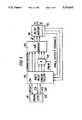
- FIG. 1is a general block diagram of the overall all-digital speed control system according to this invention.
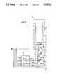
- FIGS. 2A-2Eare a detailed electrical schematic of the system of FIG. 1;
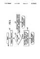
- FIG. 3is a flow chart depicting part of the operation of the controller
- FIG. 4is a flow chart depicting another aspect of the operation of the controller.
- FIG. 5is a flow chart depicting still another aspect of the operation of the controller.
- FIG. 1is a general block diagram
- FIG. 2is a more detailed electrical schematic, of the overall all-digital motor speed control system of this invention.
- Reference numeral 10identifies a brushless, three-phase, DC motor having an armature 12.
- the motoris obtained from BEI Kimco Magnetics Division of San Marcos, Calif. as its part No. DIH 23-20-BBNB.
- This motorhas a plurality of conventional Hall-effect sensors 14 mounted about the armature to sense armature position.
- the systemincludes a main digital signal processor (CPU) 16, preferably constituted as integrated circuit chip No. 87C51-PLCC.
- Main processor 16is in direct digital communication with a drive controller 18, preferably also constituted as integrated circuit chip 87C51-PLCC.
- Processor 16supplies a digital input speed signal RX indicative of a desired armature speed to the controller 18 over line 20.
- the controller 18,as will be described in detail below, supplies a digital output speed signal TX indicative of the actual armature speed to the processor 16 over line 22.
- Controller 18also communicates with the processor 16 over a RESET line 24.
- Lines 20, 22, 24are high speed serial buses capable of transmitting data at 3.75 kbaud.
- communication lines 20, 22 and 24are optical fibers.
- the main processor and the controllermay communicate by any parallel or serial communication means such as a parallel communication bus, a high speed serial hardwired interface or the like.
- controller 18Upon receipt of the input speed signal RX, controller 18 executes a software program as set forth on pages A-1 through A-3 of the attached Appendix. Controller 18 generates a set of six commutation signals, two for each phase of the motor, together operative for rotating the armature. More specifically, the controller includes an interior look-up table having a listing of six commutation bit patterns, each pattern representing a discrete command for the armature at an angular position spaced 60 electrical degrees from the previous armature position. The commutation signals are fed through, and processed in, a three-phase bridge circuit 26 and, optionally, through a bridge driver circuit (see FIG. 2), wherein three position control signals, one for each phase, are output to the motor 10. The Hall-effect sensors 14 sense rotation of the armature and generate two-state Hall-effect signals which advise the controller 18 when to generate the commutation signals.
- the generation of the commutation signalsis indicated by block 28.
- the reading of the Hall-effect sensorsis denoted by block 30. If the controller 18 recognizes that the state of the Hall-effect signals has changed (block 32), then the new state is saved (block 34) and the next commutation bit pattern is output to the motor (block 36). Thereafter, an internal counter operative for generating a tachometer (TAC) signal is incremented (block 38) prior to the next reading of the Hall-effect sensors.
- TACtachometer
- the tachometer signalis eventually processed to generate the aforementioned output speed signal TX. If the state of the Hall-effect sensors did not change in block 32, this indicates that the armature has not moved 60 electrical degrees and, hence, the controller attempts to read the Hall-effect sensors again in block 30.
- Controller 18also generates in response to command data from the processor 16, a digital pulse width modulated (PWM) signal having a duty cycle established by said command data.
- the PWM signalis carried on a carrier signal having a frequency which, in the preferred case, is 3.90625 kHz.
- Controller 18has an internal software PWM timer which, in the preferred case, establishes a PWM cycle of 256 microseconds.
- the PWM cyclehas a high and a low state.
- the PWM outputis allowed to continue running during the high state, but is re-set to OFF in the low state.
- the command datacontrols how long the PWM timer runs; in the preferred case, from 14-242 ⁇ s. In this way, the duty cycle of the PWM signal is controlled from 5.47%-94.53%.
- Block 40represents the generation of the PWM signal.
- the controllertoggles and generates a two-state PWM bit (block 42) and tests the state of the PWM bit in block 44. If the PWM bit has a low state, then, as depicted in block 46, the PWM timer is re-loaded from a command byte supplied by the processor 16. If the PWM bit has a high state, then the PWM timer is re-loaded with the 2's complement of its existing value (block 48).
- the PWM signalis fed to a drive logic unit 50 which, as shown in FIG. 2, comprises three AND gates to which three of the commutation signals are conveyed.
- Unit 50generates switching signals for the bridge 26.
- the bridge 26generates, for each phase, the aforementioned modulated control signal having an on-state and an off-state.
- the Hall-effect sensorssend TAC signals back to the controller (block 50) and, more specifically, TAC signals are accumulated as they occur every 62.5 ms in a TAC timer (block 52).
- the resulting count from the TAC counteris processed into a tachometer signal which is processed by the controller and fed back to the processor 16 over line 22, and is indicative of the actual speed of the motor.
- a watchdog counter(block 54 in FIG. 5) has a pre-set count of, for example, 500 ms. Upon receipt of the TAC timer interrupt, the watchdog counter counts down. If, as determined in block 56, the 500 ms has elapsed, then the entire system is shut down (block 58). If, however, the watchdog time has not elapsed, then the command data from the processor 16 is sent to the controller over line 20 as denoted in block 60.
Landscapes
- Engineering & Computer Science (AREA)
- Power Engineering (AREA)
- Control Of Motors That Do Not Use Commutators (AREA)
Abstract
Description
1. Field of the Invention
This invention generally relates to an all-digital motor control system and, more particularly, to a system for controlling the speed or armature position of a brushless, three-phase, DC motor.
2. Description of Related Art
Speed control systems for controlling the speed of a brushless DC motor are generally known. However, such systems rely, at least in part, on analog signals and analog-to-digital converters to convert the analog signals to digital signals for subsequent processing by digital signal processors. This adds hardware complexity and rigidity to the overall system, and the reliance on analog signals, at least in part, introduces an element of inaccuracy in motor speed control.
1. Objects of the Invention
It is a general object of this invention to advance the state of the art of speed control systems for brushless, three-phase, DC motors.
It is another object of this invention to reduce the hardware requirement and system rigidity in such speed control systems.
Another object of this invention is to provide all-digital accuracy in such motor speed control systems.
2. Features of the Invention
In keeping with these objects, and others which will become apparent hereinafter, one feature of this invention resides, briefly stated, in an all-digital control system for a brushless, three-phase, DC motor having an armature. The system comprises a main digital signal processor for supplying a digital command signal indicative of a desired motor operation. A drive controller in direct digital communication with the main processor generates, for each phase, and in response to the command signal, a digital commutation signal to rotate the armature, as well as a digital pulse width modulated signal having a duty cycle established by the input command signal.
The system further comprises switching means, e.g. a three-phase bridge, in digital communication with the controller. The bridge is operative for generating, for each phase, and in response to each commutation signal and each pulse width modulated signal, a digital two-state control signal having an onstate which lasts for the duty cycle.
The system still further comprises means in digital communication with the controller, for generating, for each phase, a digital tachometer signal indicative of armature position. The controller is further operative for processing the tachometer signal to generate a digital output signal indicative of the actual armature speed or position. The controller directly digitally communicates the output signal to the main processor.
In a preferred embodiment, the main processor and the drive controller are interconnected by, and digitally communicate through, a plurality of optical fibers. No analog signals and, of course, no analog-to-digital converters, are used anywhere in the speed control system, thereby simplifying the hardware requirement for such system, and also eliminating any inaccuracies due to the presence of analog signals.
Another feature of this invention resides in shutting down the system upon the elapse of a predetermined time during which no input signal is received by the controller.
The novel features which are considered as characteristic of the invention are set forth in particular in the appended claims. The invention itself, however, both as to its construction and its method of operation, together with additional objects and advantages thereof, will be best understood from the following description of specific embodiments when read in connection with the accompanying drawings.
FIG. 1 is a general block diagram of the overall all-digital speed control system according to this invention;
FIGS. 2A-2E are a detailed electrical schematic of the system of FIG. 1;
FIG. 3 is a flow chart depicting part of the operation of the controller;
FIG. 4 is a flow chart depicting another aspect of the operation of the controller; and
FIG. 5 is a flow chart depicting still another aspect of the operation of the controller.
The present invention is illustrated in terms of a control system for controlling the speed of a brushless three-phase, DC motor. Referring now to the drawings, FIG. 1 is a general block diagram, and FIG. 2 is a more detailed electrical schematic, of the overall all-digital motor speed control system of this invention.Reference numeral 10 identifies a brushless, three-phase, DC motor having anarmature 12. Preferably, the motor is obtained from BEI Kimco Magnetics Division of San Marcos, Calif. as its part No. DIH 23-20-BBNB. This motor has a plurality of conventional Hall-effect sensors 14 mounted about the armature to sense armature position.
The system includes a main digital signal processor (CPU) 16, preferably constituted as integrated circuit chip No. 87C51-PLCC.Main processor 16 is in direct digital communication with adrive controller 18, preferably also constituted as integrated circuit chip 87C51-PLCC.Processor 16 supplies a digital input speed signal RX indicative of a desired armature speed to thecontroller 18 overline 20. Thecontroller 18, as will be described in detail below, supplies a digital output speed signal TX indicative of the actual armature speed to theprocessor 16 overline 22.Controller 18 also communicates with theprocessor 16 over aRESET line 24.Lines communication lines
Upon receipt of the input speed signal RX,controller 18 executes a software program as set forth on pages A-1 through A-3 of the attached Appendix.Controller 18 generates a set of six commutation signals, two for each phase of the motor, together operative for rotating the armature. More specifically, the controller includes an interior look-up table having a listing of six commutation bit patterns, each pattern representing a discrete command for the armature at an angular position spaced 60 electrical degrees from the previous armature position. The commutation signals are fed through, and processed in, a three-phase bridge circuit 26 and, optionally, through a bridge driver circuit (see FIG. 2), wherein three position control signals, one for each phase, are output to themotor 10. The Hall-effect sensors 14 sense rotation of the armature and generate two-state Hall-effect signals which advise thecontroller 18 when to generate the commutation signals.
This latter aspect of the operation of thecontroller 18 is displayed in the flow chart of FIG. 3. The generation of the commutation signals is indicated byblock 28. The reading of the Hall-effect sensors is denoted byblock 30. If thecontroller 18 recognizes that the state of the Hall-effect signals has changed (block 32), then the new state is saved (block 34) and the next commutation bit pattern is output to the motor (block 36). Thereafter, an internal counter operative for generating a tachometer (TAC) signal is incremented (block 38) prior to the next reading of the Hall-effect sensors. The tachometer signal is eventually processed to generate the aforementioned output speed signal TX. If the state of the Hall-effect sensors did not change inblock 32, this indicates that the armature has not moved 60 electrical degrees and, hence, the controller attempts to read the Hall-effect sensors again inblock 30.
This aspect of the controller operation is depicted in FIG. 4.Block 40 represents the generation of the PWM signal. The controller toggles and generates a two-state PWM bit (block 42) and tests the state of the PWM bit inblock 44. If the PWM bit has a low state, then, as depicted inblock 46, the PWM timer is re-loaded from a command byte supplied by theprocessor 16. If the PWM bit has a high state, then the PWM timer is re-loaded with the 2's complement of its existing value (block 48).
As best shown in FIG. 1, the PWM signal is fed to adrive logic unit 50 which, as shown in FIG. 2, comprises three AND gates to which three of the commutation signals are conveyed.Unit 50 generates switching signals for thebridge 26. In turn, thebridge 26 generates, for each phase, the aforementioned modulated control signal having an on-state and an off-state.
As shown in the flow chart of FIG. 5, the Hall-effect sensors, as previously mentioned, send TAC signals back to the controller (block 50) and, more specifically, TAC signals are accumulated as they occur every 62.5 ms in a TAC timer (block 52). The resulting count from the TAC counter is processed into a tachometer signal which is processed by the controller and fed back to theprocessor 16 overline 22, and is indicative of the actual speed of the motor.
In accordance with another feature of this invention, a watchdog counter (block 54 in FIG. 5) has a pre-set count of, for example, 500 ms. Upon receipt of the TAC timer interrupt, the watchdog counter counts down. If, as determined inblock 56, the 500 ms has elapsed, then the entire system is shut down (block 58). If, however, the watchdog time has not elapsed, then the command data from theprocessor 16 is sent to the controller overline 20 as denoted inblock 60.
It will be understood that each of the elements described above, or two or more together, also may find a useful application in other types of constructions differing from the types described above.
While the invention has been illustrated and described as embodied in an all-digital speed control system for brushless three-phase DC motor, it is not intended to be limited to the details shown, since various modifications and structural changes may be made without departing in any way from the spirit of the present invention.
Claims (9)
1. An all-digital control system for a brushless, three-phase, DC motor having an armature, comprising:
(a) a main digital signal processor for supplying a digital input command signal indicative of a desired motor operation;
(b) a drive controller in direct digital communication with the main processor, for generating, for each phase, and in response to the command signal, a digital commutation signal to rotate the armature, and a digital pulse width modulated signal having a duty cycle established by the input command signal;
(c) switching means in digital communication with the controller, for generating, for each phase, and in response to each commutation signal and each pulse width modulated signal, a digital two-state control signal having an on-state which lasts for said duty cycle;
(d) means in direct digital communication with the controller, for generating, for each phase, a digital tachometer signal indicative of armature position;
(e) said controller being further operative for processing the tachometer signal, to generate a digital output signal indicative of the actual armature speed or position, and for directly digitally communicating the output signal to the main processor, said controller including a look-up table having commutation bit patterns, each corresponding to a different armature position; and
(f) said main processor and said controller being interconnected by, and digitally communicating through, a plurality of optical fibers.
2. The system according to claim 1, wherein the main processor and the drive controller are interconnected by, and digitally communicate through, parallel or serial optical fibers.
3. The system according to claim 1, wherein the pulse width modulated signal has two states, and wherein the controller includes timer means having a timer output signal whose duration is established by the state of the pulse width modulated signal.
4. The system according to claim 1, wherein the controller includes watchdog timer means having a predetermined watchdog time, and wherein the controller includes shutdown means for ceasing generation of the commutation signals upon elapse of said watchdog time without receipt of the input command signal.
5. An all-digital speed control system for a brushless, three-phase, DC motor having an armature, comprising:
(a) a main digital signal processor for supplying a digital input speed signal indicative of a desired armature speed;
(b) a drive controller in direct digital communication with the main processor, for generating, for each phase, and in response to the input speed signal, a digital commutation signal to rotate the armature, and a digital pulse width modulated signal having a duty cycle established by the input speed signal;
(c) switching means in digital communication with the controller, for generating, for each phase, and in response to each commutation signal and each pulse width modulated signal, a digital two-state speed control signal having an on-state which lasts for said duty cycle;
(d) means in direct digital communication with the controller, for generating, for each phase, a digital tachometer signal indicative of armature position;
(e) said controller being further operative for processing the tachometer signal, to generate a digital output speed signal indicative of the actual armature speed, and for directly digitally communicating the output speed signal to the main processor, said controller including a look-up table having commutation bit patterns, each corresponding to a different armature position; and
(f) said main processor and said controller being interconnected by, and digitally communicating through, a plurality of optical fibers.
6. The system according to claim 5, wherein the duty cycle of the pulse width modulated signal lies in a range between 5.47%-94.53%.
7. The system according to claim 5, wherein the pulse width modulated signal is carried on a signal carrier having a frequency of 3.90625 kHz.
8. The system according to claim 5, wherein the pulse width modulated signal has two states, and wherein the controller includes timer means having a timer output signal whose duration is established by the state of the pulse width modulated signal.
9. The system according to claim 5, wherein the controller includes watchdog timer means having a predetermined watchdog time, and wherein the controller includes shutdown means for ceasing generation of the commutation signals upon elapse of said watchdog time without receipt of the input speed signal.
Priority Applications (11)
| Application Number | Priority Date | Filing Date | Title |
|---|---|---|---|
| US07/867,871US5270622A (en) | 1992-04-13 | 1992-04-13 | Brushless motor control system |
| CA002093242ACA2093242C (en) | 1992-04-13 | 1993-04-02 | Brushless motor control system |
| AT93302657TATE157208T1 (en) | 1992-04-13 | 1993-04-05 | CONTROL DEVICE FOR A BRUSHLESS MOTOR |
| ES93302657TES2108216T3 (en) | 1992-04-13 | 1993-04-05 | CONTROL SYSTEM OF A BRUSHLESS MOTOR. |
| EP93302657AEP0566297B1 (en) | 1992-04-13 | 1993-04-05 | Brushless motor control system |
| DE69313170TDE69313170T2 (en) | 1992-04-13 | 1993-04-05 | Control device for a brushless motor |
| AU36764/93AAU655906B2 (en) | 1992-04-13 | 1993-04-06 | Brushless motor control system |
| JP5086326AJPH0670580A (en) | 1992-04-13 | 1993-04-13 | Control system of brushless motor |
| US08/420,243US5602449A (en) | 1992-04-13 | 1995-04-11 | Motor controlled surgical system and method having positional control |
| US08/431,615US5563481A (en) | 1992-04-13 | 1995-05-01 | Brushless motor |
| US08/630,523US5672945A (en) | 1992-04-13 | 1996-04-10 | Motor controlled surgical system and method having self clearing motor control |
Applications Claiming Priority (1)
| Application Number | Priority Date | Filing Date | Title |
|---|---|---|---|
| US07/867,871US5270622A (en) | 1992-04-13 | 1992-04-13 | Brushless motor control system |
Related Child Applications (1)
| Application Number | Title | Priority Date | Filing Date |
|---|---|---|---|
| US13529793AContinuation-In-Part | 1992-04-13 | 1993-10-12 |
Publications (1)
| Publication Number | Publication Date |
|---|---|
| US5270622Atrue US5270622A (en) | 1993-12-14 |
Family
ID=25350635
Family Applications (1)
| Application Number | Title | Priority Date | Filing Date |
|---|---|---|---|
| US07/867,871Expired - LifetimeUS5270622A (en) | 1992-04-13 | 1992-04-13 | Brushless motor control system |
Country Status (8)
| Country | Link |
|---|---|
| US (1) | US5270622A (en) |
| EP (1) | EP0566297B1 (en) |
| JP (1) | JPH0670580A (en) |
| AT (1) | ATE157208T1 (en) |
| AU (1) | AU655906B2 (en) |
| CA (1) | CA2093242C (en) |
| DE (1) | DE69313170T2 (en) |
| ES (1) | ES2108216T3 (en) |
Cited By (54)
| Publication number | Priority date | Publication date | Assignee | Title |
|---|---|---|---|---|
| WO1996032067A1 (en) | 1995-04-11 | 1996-10-17 | Smith & Nephew, Inc. | Motor controlled surgical system and method having positional control |
| US5672945A (en)* | 1992-04-13 | 1997-09-30 | Smith & Nephew Endoscopy, Inc. | Motor controlled surgical system and method having self clearing motor control |
| US5767640A (en)* | 1995-09-20 | 1998-06-16 | Matsushita Electric Industrial Co., Ltd. | Brushless motor |
| US5847523A (en)* | 1995-05-25 | 1998-12-08 | Papst-Motoren Gmbh & Co. Kg | Method of limiting current in a DC motor and DC motor system for implementing said method |
| US6245084B1 (en) | 1998-10-20 | 2001-06-12 | Promex, Inc. | System for controlling a motor driven surgical cutting instrument |
| WO2001045246A3 (en)* | 1999-12-08 | 2002-02-07 | Comair Rotron Inc | Motor synchronization apparatus |
| US6463546B1 (en) | 1996-08-12 | 2002-10-08 | Papst-Motoren Gmbh & Co. Kg | Method and apparatus for monitoring a microprocessor |
| US20030020428A1 (en)* | 2001-07-24 | 2003-01-30 | Hitachi, Ltd. | Motor controller |
| US6646396B2 (en) | 1999-12-08 | 2003-11-11 | Comair Rotron, Inc. | Apparatus for motor synchronization |
| US20050186096A1 (en)* | 2004-02-20 | 2005-08-25 | Vinson Wade D. | Cooling fan for electronic device |
| US20050184605A1 (en)* | 2004-02-20 | 2005-08-25 | Vinson Wade D. | Cooling fan having three-phase DC motor |
| US7230400B1 (en)* | 1998-10-05 | 2007-06-12 | Ebm-Papst St. Georgen Gmbh & Co. Kg | Electronically commutated motor |
| US20080170841A1 (en)* | 2007-01-17 | 2008-07-17 | W&H Dentalwerk Burmoos Gmbh | Medical Handle |
| RU2351972C2 (en)* | 2007-02-20 | 2009-04-10 | Федеральное государственное унитарное предприятие "Государственный московский завод "Салют" | Electric drive control device |
| US20100100112A1 (en)* | 2008-10-22 | 2010-04-22 | Barry Kauker | Sensing arrangement for control of powered cutting device |
| CN102290790A (en)* | 2011-08-25 | 2011-12-21 | 南京航空航天大学 | Fault detecting and protective circuit of brushless direct current motor |
| US8893722B2 (en) | 1997-09-04 | 2014-11-25 | Smith & Nephew, Inc. | Surgical endoscopic cutting device and method for its use |
| US9060800B1 (en) | 2001-10-26 | 2015-06-23 | Smith & Nephew, Inc. | Reciprocating rotary arthroscopic surgical instrument |
| US9125550B2 (en) | 2004-08-27 | 2015-09-08 | Smith & Nephew, Inc. | Tissue resecting system |
| US9155454B2 (en) | 2010-09-28 | 2015-10-13 | Smith & Nephew, Inc. | Hysteroscopic system |
| US9948209B2 (en) | 2015-05-21 | 2018-04-17 | Pacific Power Source, Inc. | Digital controller architecture for three-phase AC sources |
| US10299819B2 (en) | 2016-07-28 | 2019-05-28 | Covidien Lp | Reciprocating rotary surgical cutting device and system for tissue resecting, and method for its use |
| US10299803B2 (en) | 2016-08-04 | 2019-05-28 | Covidien Lp | Self-aligning drive coupler |
| US10631889B2 (en) | 2014-12-16 | 2020-04-28 | Covidien Lp | Surgical device with incorporated tissue extraction |
| US10750931B2 (en) | 2015-05-26 | 2020-08-25 | Covidien Lp | Systems and methods for generating a fluid bearing for an operative procedure |
| US10772652B2 (en) | 2015-01-28 | 2020-09-15 | Covidien Lp | Tissue resection system |
| US10772654B2 (en) | 2017-03-02 | 2020-09-15 | Covidien Lp | Fluid-driven tissue resecting instruments, systems, and methods |
| US10799264B2 (en) | 2015-06-18 | 2020-10-13 | Covidien Lp | Surgical instrument with suction control |
| US10804769B2 (en) | 2015-06-17 | 2020-10-13 | Covidien Lp | Surgical instrument with phase change cooling |
| US10842350B2 (en) | 2015-06-17 | 2020-11-24 | Covidien Lp | Endoscopic device with drip flange and methods of use thereof for an operative procedure |
| US10869684B2 (en) | 2018-02-13 | 2020-12-22 | Covidien Lp | Powered tissue resecting device |
| US10898218B2 (en) | 2019-02-25 | 2021-01-26 | Covidien Lp | Tissue resecting device including a motor cooling assembly |
| US10945752B2 (en) | 2019-03-20 | 2021-03-16 | Covidien Lp | Tissue resecting instrument including a rotation lock feature |
| US11065147B2 (en) | 2018-10-18 | 2021-07-20 | Covidien Lp | Devices, systems, and methods for pre-heating fluid to be introduced into a patient during a surgical procedure |
| US11083481B2 (en) | 2019-02-22 | 2021-08-10 | Covidien Lp | Tissue resecting instrument including an outflow control seal |
| US11154318B2 (en) | 2019-02-22 | 2021-10-26 | Covidien Lp | Tissue resecting instrument including an outflow control seal |
| US11179172B2 (en) | 2019-12-05 | 2021-11-23 | Covidien Lp | Tissue resecting instrument |
| US11197710B2 (en) | 2018-10-26 | 2021-12-14 | Covidien Lp | Tissue resecting device including a blade lock and release mechanism |
| US11317947B2 (en) | 2020-02-18 | 2022-05-03 | Covidien Lp | Tissue resecting instrument |
| US11376032B2 (en) | 2019-12-05 | 2022-07-05 | Covidien Lp | Tissue resecting instrument |
| US11452806B2 (en) | 2019-10-04 | 2022-09-27 | Covidien Lp | Outflow collection vessels, systems, and components thereof for hysteroscopic surgical procedures |
| US11547782B2 (en) | 2020-01-31 | 2023-01-10 | Covidien Lp | Fluid collecting sheaths for endoscopic devices and systems |
| US11547815B2 (en) | 2018-05-30 | 2023-01-10 | Covidien Lp | Systems and methods for measuring and controlling pressure within an internal body cavity |
| US11553977B2 (en) | 2019-05-29 | 2023-01-17 | Covidien Lp | Hysteroscopy systems and methods for managing patient fluid |
| US11571233B2 (en) | 2020-11-19 | 2023-02-07 | Covidien Lp | Tissue removal handpiece with integrated suction |
| US11596429B2 (en) | 2020-04-20 | 2023-03-07 | Covidien Lp | Tissue resecting instrument |
| US11696782B2 (en) | 2017-12-12 | 2023-07-11 | Boston Scientific Scimed, Inc. | Rotational medical device |
| US11737777B2 (en) | 2020-02-05 | 2023-08-29 | Covidien Lp | Tissue resecting instruments |
| US11864735B2 (en) | 2016-05-26 | 2024-01-09 | Covidien Lp | Continuous flow endoscope |
| US11883058B2 (en) | 2019-03-26 | 2024-01-30 | Covidien Lp | Jaw members, end effector assemblies, and ultrasonic surgical instruments including the same |
| US11890237B2 (en) | 2019-10-04 | 2024-02-06 | Covidien Lp | Outflow collection vessels, systems, and components thereof for hysteroscopic surgical procedures |
| US12156673B2 (en) | 2020-10-07 | 2024-12-03 | Covidien Lp | Temperature measurement device for a handpiece of a surgical instrument |
| US12303109B2 (en) | 2021-12-22 | 2025-05-20 | Covidien Lp | Surgical systems and methods for component cooling while warming fluid to be introduced during a surgical procedure |
| US12364500B2 (en) | 2021-05-26 | 2025-07-22 | Covidien Lp | Tissue resecting instrument |
Families Citing this family (8)
| Publication number | Priority date | Publication date | Assignee | Title |
|---|---|---|---|---|
| ES2138650T3 (en)* | 1993-10-12 | 2000-01-16 | Smith & Nephew Inc | BRUSHLESS MOTOR. |
| US5590235A (en)* | 1993-12-03 | 1996-12-31 | Papst-Motoren Gmbh & Co. Kg | DC motor control with periodic reset |
| JPH07337076A (en)* | 1994-06-07 | 1995-12-22 | Matsushita Electric Ind Co Ltd | 3-phase brushless servomotor |
| US5625424A (en)* | 1994-11-14 | 1997-04-29 | Texas Instruments Incorporated | Digital motor controller for color wheel |
| DE19502306A1 (en)* | 1995-01-26 | 1996-08-08 | Kostal Leopold Gmbh & Co Kg | Control of permanent magnet type electronically commutated DC motor for driving motor vehicle control actuators |
| JPH11356087A (en)* | 1998-06-08 | 1999-12-24 | Matsushita Electric Ind Co Ltd | 3-phase brushless servomotor |
| CN103066900B (en)* | 2013-01-05 | 2015-10-14 | 上海交通大学 | Pipeline compressor synchronous motor digital control system based on IGCT five-level technology |
| JP6240955B2 (en)* | 2013-10-30 | 2017-12-06 | コニカミノルタ株式会社 | Motor control device and image forming apparatus having the same |
Citations (11)
| Publication number | Priority date | Publication date | Assignee | Title |
|---|---|---|---|---|
| US4400654A (en)* | 1981-03-27 | 1983-08-23 | Magnetic Peripherals Inc. | Digital speed control for a brushless DC motor |
| US4415844A (en)* | 1981-02-09 | 1983-11-15 | Priam | Digital motor speed controller |
| JPS6051492A (en)* | 1983-08-31 | 1985-03-22 | Ricoh Co Ltd | Drive system of brushless motor |
| US4680513A (en)* | 1986-08-11 | 1987-07-14 | Harbor Branch Oceanographic Institute Inc. | Electric motor reversing control devices |
| US4680515A (en)* | 1985-05-21 | 1987-07-14 | Crook James C | Digital speed control of motors |
| US4701839A (en)* | 1984-11-09 | 1987-10-20 | International Cybernetic Corporation | Sampled data servo control system with field orientation |
| US4720663A (en)* | 1986-03-31 | 1988-01-19 | United Technologies Electro Systems, Inc. | Brushless motor speed control |
| US4786847A (en)* | 1986-11-20 | 1988-11-22 | Unimation Inc. | Digital control for multiaxis robots |
| US4868469A (en)* | 1988-05-16 | 1989-09-19 | Advanced Micro Devices, Inc. | Multi-way polling, branching and waiting opcode |
| US5079487A (en)* | 1989-12-14 | 1992-01-07 | North America Philips Corporation | Anti-backdrive commutation of brushless DC motors |
| WO1992001330A1 (en)* | 1990-07-10 | 1992-01-23 | Allied-Signal Inc. | Digital motor controller |
Family Cites Families (5)
| Publication number | Priority date | Publication date | Assignee | Title |
|---|---|---|---|---|
| JP2674024B2 (en)* | 1987-06-25 | 1997-11-05 | トヨタ自動車株式会社 | Servo controller |
| JPH01227596A (en)* | 1988-03-07 | 1989-09-11 | Mitsubishi Electric Corp | Inverter remote control device |
| JPH02299496A (en)* | 1989-05-12 | 1990-12-11 | Nippon Steel Corp | Driving method for brushless dc motor |
| JPH0475492A (en)* | 1990-07-12 | 1992-03-10 | Matsushita Electric Ind Co Ltd | Servo motor control device |
| JPH04213707A (en)* | 1990-12-12 | 1992-08-04 | Canon Inc | Angular positioning device |
- 1992
- 1992-04-13USUS07/867,871patent/US5270622A/ennot_activeExpired - Lifetime
- 1993
- 1993-04-02CACA002093242Apatent/CA2093242C/ennot_activeExpired - Fee Related
- 1993-04-05DEDE69313170Tpatent/DE69313170T2/ennot_activeExpired - Lifetime
- 1993-04-05ESES93302657Tpatent/ES2108216T3/ennot_activeExpired - Lifetime
- 1993-04-05EPEP93302657Apatent/EP0566297B1/ennot_activeExpired - Lifetime
- 1993-04-05ATAT93302657Tpatent/ATE157208T1/ennot_activeIP Right Cessation
- 1993-04-06AUAU36764/93Apatent/AU655906B2/ennot_activeExpired
- 1993-04-13JPJP5086326Apatent/JPH0670580A/enactivePending
Patent Citations (11)
| Publication number | Priority date | Publication date | Assignee | Title |
|---|---|---|---|---|
| US4415844A (en)* | 1981-02-09 | 1983-11-15 | Priam | Digital motor speed controller |
| US4400654A (en)* | 1981-03-27 | 1983-08-23 | Magnetic Peripherals Inc. | Digital speed control for a brushless DC motor |
| JPS6051492A (en)* | 1983-08-31 | 1985-03-22 | Ricoh Co Ltd | Drive system of brushless motor |
| US4701839A (en)* | 1984-11-09 | 1987-10-20 | International Cybernetic Corporation | Sampled data servo control system with field orientation |
| US4680515A (en)* | 1985-05-21 | 1987-07-14 | Crook James C | Digital speed control of motors |
| US4720663A (en)* | 1986-03-31 | 1988-01-19 | United Technologies Electro Systems, Inc. | Brushless motor speed control |
| US4680513A (en)* | 1986-08-11 | 1987-07-14 | Harbor Branch Oceanographic Institute Inc. | Electric motor reversing control devices |
| US4786847A (en)* | 1986-11-20 | 1988-11-22 | Unimation Inc. | Digital control for multiaxis robots |
| US4868469A (en)* | 1988-05-16 | 1989-09-19 | Advanced Micro Devices, Inc. | Multi-way polling, branching and waiting opcode |
| US5079487A (en)* | 1989-12-14 | 1992-01-07 | North America Philips Corporation | Anti-backdrive commutation of brushless DC motors |
| WO1992001330A1 (en)* | 1990-07-10 | 1992-01-23 | Allied-Signal Inc. | Digital motor controller |
Cited By (99)
| Publication number | Priority date | Publication date | Assignee | Title |
|---|---|---|---|---|
| US5602449A (en)* | 1992-04-13 | 1997-02-11 | Smith & Nephew Endoscopy, Inc. | Motor controlled surgical system and method having positional control |
| US5672945A (en)* | 1992-04-13 | 1997-09-30 | Smith & Nephew Endoscopy, Inc. | Motor controlled surgical system and method having self clearing motor control |
| WO1996032067A1 (en) | 1995-04-11 | 1996-10-17 | Smith & Nephew, Inc. | Motor controlled surgical system and method having positional control |
| US5847523A (en)* | 1995-05-25 | 1998-12-08 | Papst-Motoren Gmbh & Co. Kg | Method of limiting current in a DC motor and DC motor system for implementing said method |
| US5767640A (en)* | 1995-09-20 | 1998-06-16 | Matsushita Electric Industrial Co., Ltd. | Brushless motor |
| US5969490A (en)* | 1995-09-20 | 1999-10-19 | Matsushita Electric Industrial Co., Ltd. | Brushless motor for providing precise driving signal in presence of variations in output amplitude of position detecting signal |
| WO1997045054A2 (en) | 1996-04-10 | 1997-12-04 | Smith & Nephew, Inc. | Motor controlled surgical system and method having self clearing motor control |
| US6463546B1 (en) | 1996-08-12 | 2002-10-08 | Papst-Motoren Gmbh & Co. Kg | Method and apparatus for monitoring a microprocessor |
| US9750520B2 (en) | 1997-09-04 | 2017-09-05 | Covidien Lp | Surgical endoscopic cutting device and method for its use |
| US9089358B2 (en) | 1997-09-04 | 2015-07-28 | Smith & Nephew, Inc. | Surgical cutting device and method for its use |
| US8893722B2 (en) | 1997-09-04 | 2014-11-25 | Smith & Nephew, Inc. | Surgical endoscopic cutting device and method for its use |
| US9226765B2 (en) | 1997-09-04 | 2016-01-05 | Smith & Nephew, Inc. | Surgical cutting device and method for its use |
| US9226650B2 (en) | 1997-09-04 | 2016-01-05 | Smith & Nephew, Inc. | Surgical cutting device and method for its use |
| US9427247B2 (en) | 1997-09-04 | 2016-08-30 | Smith & Nephew, Inc. | Surgical cutting device and method for its use |
| US7230400B1 (en)* | 1998-10-05 | 2007-06-12 | Ebm-Papst St. Georgen Gmbh & Co. Kg | Electronically commutated motor |
| US6245084B1 (en) | 1998-10-20 | 2001-06-12 | Promex, Inc. | System for controlling a motor driven surgical cutting instrument |
| US6358263B2 (en) | 1998-10-20 | 2002-03-19 | Promex, Inc. | System for controlling a motor driven surgical cutting instrument |
| WO2001045246A3 (en)* | 1999-12-08 | 2002-02-07 | Comair Rotron Inc | Motor synchronization apparatus |
| US6646396B2 (en) | 1999-12-08 | 2003-11-11 | Comair Rotron, Inc. | Apparatus for motor synchronization |
| US6844697B2 (en)* | 2001-07-24 | 2005-01-18 | Hitachi, Ltd. | Motor controller |
| US20030020428A1 (en)* | 2001-07-24 | 2003-01-30 | Hitachi, Ltd. | Motor controller |
| US9060800B1 (en) | 2001-10-26 | 2015-06-23 | Smith & Nephew, Inc. | Reciprocating rotary arthroscopic surgical instrument |
| US9066745B2 (en) | 2001-10-26 | 2015-06-30 | Smith & Nephew, Inc. | Reciprocating rotary arthroscopic surgical instrument |
| US9636130B2 (en) | 2001-10-26 | 2017-05-02 | Covidien Lp | Reciprocating rotary arthroscopic surgical instrument |
| US9060801B1 (en) | 2001-10-26 | 2015-06-23 | Smith & Nephew, Inc. | Reciprocating rotary arthroscopic surgical instrument |
| US10441306B2 (en) | 2001-10-26 | 2019-10-15 | Covidien Lp | Reciprocating rotary arthroscopic surgical instrument |
| US8647077B2 (en) | 2004-02-20 | 2014-02-11 | Hewlett-Packard Development Company, L.P. | Cooling fan for electronic device |
| US20050184605A1 (en)* | 2004-02-20 | 2005-08-25 | Vinson Wade D. | Cooling fan having three-phase DC motor |
| US20050186096A1 (en)* | 2004-02-20 | 2005-08-25 | Vinson Wade D. | Cooling fan for electronic device |
| US10939810B2 (en) | 2004-08-27 | 2021-03-09 | Covidien Lp | Tissue resecting system |
| US10076237B2 (en) | 2004-08-27 | 2018-09-18 | Covidien Lp | Tissue resecting system |
| US9125550B2 (en) | 2004-08-27 | 2015-09-08 | Smith & Nephew, Inc. | Tissue resecting system |
| US9936861B2 (en) | 2004-08-27 | 2018-04-10 | Covidien Lp | Tissue resecting system |
| EP1946706A1 (en)* | 2007-01-17 | 2008-07-23 | W & H Dentalwerk Bürmoos GmbH | Medical handle |
| US20080170841A1 (en)* | 2007-01-17 | 2008-07-17 | W&H Dentalwerk Burmoos Gmbh | Medical Handle |
| US9451976B2 (en) | 2007-01-17 | 2016-09-27 | Arthrex, Inc. | Medical handle |
| RU2351972C2 (en)* | 2007-02-20 | 2009-04-10 | Федеральное государственное унитарное предприятие "Государственный московский завод "Салют" | Electric drive control device |
| US20100100112A1 (en)* | 2008-10-22 | 2010-04-22 | Barry Kauker | Sensing arrangement for control of powered cutting device |
| US8226677B2 (en) | 2008-10-22 | 2012-07-24 | Stryker Corporation | Sensing arrangement for control of powered cutting device |
| US9155454B2 (en) | 2010-09-28 | 2015-10-13 | Smith & Nephew, Inc. | Hysteroscopic system |
| US11229354B2 (en) | 2010-09-28 | 2022-01-25 | Covidien Lp | Hysteroscopic system |
| US10251539B2 (en) | 2010-09-28 | 2019-04-09 | Covidien Lp | Hysteroscopic system |
| US12369788B2 (en) | 2010-09-28 | 2025-07-29 | Covidien Lp | Hysteroscopic system |
| US11889993B2 (en) | 2010-09-28 | 2024-02-06 | Covidien Lp | Hysteroscopic system |
| CN102290790A (en)* | 2011-08-25 | 2011-12-21 | 南京航空航天大学 | Fault detecting and protective circuit of brushless direct current motor |
| CN102290790B (en)* | 2011-08-25 | 2014-01-29 | 南京航空航天大学 | A Fault Detection and Protection Circuit for Brushless DC Motor |
| US10631889B2 (en) | 2014-12-16 | 2020-04-28 | Covidien Lp | Surgical device with incorporated tissue extraction |
| US11871952B2 (en) | 2014-12-16 | 2024-01-16 | Covidien Lp | Surgical device with incorporated tissue extraction |
| US10772652B2 (en) | 2015-01-28 | 2020-09-15 | Covidien Lp | Tissue resection system |
| US11666354B2 (en) | 2015-01-28 | 2023-06-06 | Covidien Lp | Tissue resection system |
| US9948209B2 (en) | 2015-05-21 | 2018-04-17 | Pacific Power Source, Inc. | Digital controller architecture for three-phase AC sources |
| US10750931B2 (en) | 2015-05-26 | 2020-08-25 | Covidien Lp | Systems and methods for generating a fluid bearing for an operative procedure |
| US11659977B2 (en) | 2015-06-17 | 2023-05-30 | Covidien Lp | Endoscopic device with drip flange and methods of use thereof for an operative procedure |
| US10804769B2 (en) | 2015-06-17 | 2020-10-13 | Covidien Lp | Surgical instrument with phase change cooling |
| US10842350B2 (en) | 2015-06-17 | 2020-11-24 | Covidien Lp | Endoscopic device with drip flange and methods of use thereof for an operative procedure |
| US10799264B2 (en) | 2015-06-18 | 2020-10-13 | Covidien Lp | Surgical instrument with suction control |
| US11712262B2 (en) | 2015-06-18 | 2023-08-01 | Covidien Lp | Surgical instrument with suction control |
| US12268412B2 (en) | 2015-06-18 | 2025-04-08 | Covidien Lp | Surgical instrument with suction control |
| US11864735B2 (en) | 2016-05-26 | 2024-01-09 | Covidien Lp | Continuous flow endoscope |
| US12076041B2 (en) | 2016-07-28 | 2024-09-03 | Covidien Lp | Reciprocating rotary surgical cutting device and system for tissue resecting, and method for its use |
| US11172954B2 (en) | 2016-07-28 | 2021-11-16 | Covidien Lp | Reciprocating rotary surgical cutting device and system for tissue resecting, and method for its use |
| US10299819B2 (en) | 2016-07-28 | 2019-05-28 | Covidien Lp | Reciprocating rotary surgical cutting device and system for tissue resecting, and method for its use |
| US10299803B2 (en) | 2016-08-04 | 2019-05-28 | Covidien Lp | Self-aligning drive coupler |
| US10772654B2 (en) | 2017-03-02 | 2020-09-15 | Covidien Lp | Fluid-driven tissue resecting instruments, systems, and methods |
| US11622787B2 (en) | 2017-03-02 | 2023-04-11 | Covidien Lp | Fluid-driven tissue resecting instruments, systems, and methods |
| US11696782B2 (en) | 2017-12-12 | 2023-07-11 | Boston Scientific Scimed, Inc. | Rotational medical device |
| US11806036B2 (en) | 2018-02-13 | 2023-11-07 | Covidien Lp | Powered tissue resecting device |
| US10869684B2 (en) | 2018-02-13 | 2020-12-22 | Covidien Lp | Powered tissue resecting device |
| US12370329B2 (en) | 2018-05-30 | 2025-07-29 | Covidien Lp | Systems and methods for measuring and controlling pressure within an internal body cavity |
| US11547815B2 (en) | 2018-05-30 | 2023-01-10 | Covidien Lp | Systems and methods for measuring and controlling pressure within an internal body cavity |
| US11065147B2 (en) | 2018-10-18 | 2021-07-20 | Covidien Lp | Devices, systems, and methods for pre-heating fluid to be introduced into a patient during a surgical procedure |
| US12324768B2 (en) | 2018-10-18 | 2025-06-10 | Covidien Lp | Devices, systems, and methods for pre-heating fluid to be introduced into a patient during a surgical procedure |
| US11197710B2 (en) | 2018-10-26 | 2021-12-14 | Covidien Lp | Tissue resecting device including a blade lock and release mechanism |
| US12376899B2 (en) | 2018-10-26 | 2025-08-05 | Covidien Lp | Tissue resecting device including a blade lock and release mechanism |
| US11744606B2 (en) | 2019-02-22 | 2023-09-05 | Covidien Lp | Tissue resecting instrument including an outflow control seal |
| US11083481B2 (en) | 2019-02-22 | 2021-08-10 | Covidien Lp | Tissue resecting instrument including an outflow control seal |
| US11154318B2 (en) | 2019-02-22 | 2021-10-26 | Covidien Lp | Tissue resecting instrument including an outflow control seal |
| US11871950B2 (en) | 2019-02-25 | 2024-01-16 | Covidien Lp | Tissue resecting device including a motor cooling assembly |
| US10898218B2 (en) | 2019-02-25 | 2021-01-26 | Covidien Lp | Tissue resecting device including a motor cooling assembly |
| US11819234B2 (en) | 2019-03-20 | 2023-11-21 | Covidien Lp | Tissue resecting instrument including a rotation lock feature |
| US12285186B2 (en) | 2019-03-20 | 2025-04-29 | Covidien Lp | Tissue resecting instrument including a rotation lock feature |
| US10945752B2 (en) | 2019-03-20 | 2021-03-16 | Covidien Lp | Tissue resecting instrument including a rotation lock feature |
| US11883058B2 (en) | 2019-03-26 | 2024-01-30 | Covidien Lp | Jaw members, end effector assemblies, and ultrasonic surgical instruments including the same |
| US11553977B2 (en) | 2019-05-29 | 2023-01-17 | Covidien Lp | Hysteroscopy systems and methods for managing patient fluid |
| US11452806B2 (en) | 2019-10-04 | 2022-09-27 | Covidien Lp | Outflow collection vessels, systems, and components thereof for hysteroscopic surgical procedures |
| US11890237B2 (en) | 2019-10-04 | 2024-02-06 | Covidien Lp | Outflow collection vessels, systems, and components thereof for hysteroscopic surgical procedures |
| US11376032B2 (en) | 2019-12-05 | 2022-07-05 | Covidien Lp | Tissue resecting instrument |
| US11980382B2 (en) | 2019-12-05 | 2024-05-14 | Covidien Lp | Tissue resecting instrument |
| US11179172B2 (en) | 2019-12-05 | 2021-11-23 | Covidien Lp | Tissue resecting instrument |
| US11547782B2 (en) | 2020-01-31 | 2023-01-10 | Covidien Lp | Fluid collecting sheaths for endoscopic devices and systems |
| US11737777B2 (en) | 2020-02-05 | 2023-08-29 | Covidien Lp | Tissue resecting instruments |
| US12076049B2 (en) | 2020-02-18 | 2024-09-03 | Covidien Lp | Tissue resecting instrument |
| US11317947B2 (en) | 2020-02-18 | 2022-05-03 | Covidien Lp | Tissue resecting instrument |
| US12226115B2 (en) | 2020-04-20 | 2025-02-18 | Covidien Lp | Tissue resecting instrument |
| US11596429B2 (en) | 2020-04-20 | 2023-03-07 | Covidien Lp | Tissue resecting instrument |
| US12156673B2 (en) | 2020-10-07 | 2024-12-03 | Covidien Lp | Temperature measurement device for a handpiece of a surgical instrument |
| US11571233B2 (en) | 2020-11-19 | 2023-02-07 | Covidien Lp | Tissue removal handpiece with integrated suction |
| US12364500B2 (en) | 2021-05-26 | 2025-07-22 | Covidien Lp | Tissue resecting instrument |
| US12303109B2 (en) | 2021-12-22 | 2025-05-20 | Covidien Lp | Surgical systems and methods for component cooling while warming fluid to be introduced during a surgical procedure |
Also Published As
| Publication number | Publication date |
|---|---|
| CA2093242A1 (en) | 1993-10-14 |
| DE69313170D1 (en) | 1997-09-25 |
| ATE157208T1 (en) | 1997-09-15 |
| AU655906B2 (en) | 1995-01-12 |
| EP0566297A1 (en) | 1993-10-20 |
| CA2093242C (en) | 2002-07-09 |
| ES2108216T3 (en) | 1997-12-16 |
| JPH0670580A (en) | 1994-03-11 |
| EP0566297B1 (en) | 1997-08-20 |
| DE69313170T2 (en) | 1998-02-12 |
| AU3676493A (en) | 1993-10-14 |
Similar Documents
| Publication | Publication Date | Title |
|---|---|---|
| US5270622A (en) | Brushless motor control system | |
| EP0538387B1 (en) | Digital motor controller | |
| EP1295386B1 (en) | Drive circuit for a brushless dc motor | |
| EP0061824B1 (en) | A digital speed control device for a motor | |
| EP0469872A2 (en) | Isolated adjustable frequency AC inverter control | |
| GB2092780A (en) | Digital motor speed controller | |
| EP0094763B1 (en) | Pulse motor control device | |
| US5726881A (en) | Centrifugal apparatus with overspeed protection | |
| US5777448A (en) | Circuit for controlling brushless DC motor | |
| US4818927A (en) | Acceleration/deceleration control apparatus using slip speed | |
| JPS5622598A (en) | Starting system for pulse motor | |
| JPS6346678B2 (en) | ||
| JPS6346677B2 (en) | ||
| EP0178629B1 (en) | Positioning indexing control device for inverter apparatus | |
| JP2001134321A (en) | Numerical control unit | |
| JPS6346676B2 (en) | ||
| KR0129983B1 (en) | Motor control apparatus | |
| JPH1127986A (en) | Motor controller | |
| JPS63314191A (en) | Motor speed control device | |
| JPH04355682A (en) | Positioning device | |
| JPH0715358Y2 (en) | Stepping motor control circuit | |
| JP2576956B2 (en) | Industrial robot rotation angle detector | |
| JPS6387188A (en) | Operation control command issuing method of power driving device for servomotor | |
| SU1607068A1 (en) | Electric drive | |
| KR910002595B1 (en) | Speed controller |
Legal Events
| Date | Code | Title | Description |
|---|---|---|---|
| AS | Assignment | Owner name:SMITH & NEPHEW DYONICS, INC., MASSACHUSETTS Free format text:ASSIGNMENT OF ASSIGNORS INTEREST.;ASSIGNOR:KRAUSE, KENNETH W.;REEL/FRAME:006135/0902 Effective date:19920423 | |
| STCF | Information on status: patent grant | Free format text:PATENTED CASE | |
| CC | Certificate of correction | ||
| FPAY | Fee payment | Year of fee payment:4 | |
| FPAY | Fee payment | Year of fee payment:8 | |
| FPAY | Fee payment | Year of fee payment:12 |