US5269797A - Cervical discectomy instruments - Google Patents
Cervical discectomy instrumentsDownload PDFInfo
- Publication number
- US5269797A US5269797AUS07/758,013US75801391AUS5269797AUS 5269797 AUS5269797 AUS 5269797AUS 75801391 AUS75801391 AUS 75801391AUS 5269797 AUS5269797 AUS 5269797A
- Authority
- US
- United States
- Prior art keywords
- handle members
- bias means
- handle
- tool
- bore
- Prior art date
- Legal status (The legal status is an assumption and is not a legal conclusion. Google has not performed a legal analysis and makes no representation as to the accuracy of the status listed.)
- Expired - Lifetime
Links
Images


Classifications
- A—HUMAN NECESSITIES
- A61—MEDICAL OR VETERINARY SCIENCE; HYGIENE
- A61B—DIAGNOSIS; SURGERY; IDENTIFICATION
- A61B17/00—Surgical instruments, devices or methods
- A61B17/16—Instruments for performing osteoclasis; Drills or chisels for bones; Trepans
- A61B17/1604—Chisels; Rongeurs; Punches; Stamps
- A—HUMAN NECESSITIES
- A61—MEDICAL OR VETERINARY SCIENCE; HYGIENE
- A61B—DIAGNOSIS; SURGERY; IDENTIFICATION
- A61B17/00—Surgical instruments, devices or methods
- A61B17/32—Surgical cutting instruments
- A61B17/320016—Endoscopic cutting instruments, e.g. arthroscopes, resectoscopes
- A—HUMAN NECESSITIES
- A61—MEDICAL OR VETERINARY SCIENCE; HYGIENE
- A61B—DIAGNOSIS; SURGERY; IDENTIFICATION
- A61B17/00—Surgical instruments, devices or methods
- A61B17/34—Trocars; Puncturing needles
- A61B17/3417—Details of tips or shafts, e.g. grooves, expandable, bendable; Multiple coaxial sliding cannulas, e.g. for dilating
- A—HUMAN NECESSITIES
- A61—MEDICAL OR VETERINARY SCIENCE; HYGIENE
- A61B—DIAGNOSIS; SURGERY; IDENTIFICATION
- A61B17/00—Surgical instruments, devices or methods
- A61B17/28—Surgical forceps
- A61B17/29—Forceps for use in minimally invasive surgery
- A61B17/2909—Handles
- A—HUMAN NECESSITIES
- A61—MEDICAL OR VETERINARY SCIENCE; HYGIENE
- A61B—DIAGNOSIS; SURGERY; IDENTIFICATION
- A61B17/00—Surgical instruments, devices or methods
- A61B17/32—Surgical cutting instruments
- A61B17/3205—Excision instruments
- A61B17/3207—Atherectomy devices working by cutting or abrading; Similar devices specially adapted for non-vascular obstructions
- A61B17/320708—Curettes, e.g. hollow scraping instruments
- A—HUMAN NECESSITIES
- A61—MEDICAL OR VETERINARY SCIENCE; HYGIENE
- A61B—DIAGNOSIS; SURGERY; IDENTIFICATION
- A61B17/00—Surgical instruments, devices or methods
- A61B17/00234—Surgical instruments, devices or methods for minimally invasive surgery
- A61B2017/00238—Type of minimally invasive operation
- A61B2017/00261—Discectomy
- A—HUMAN NECESSITIES
- A61—MEDICAL OR VETERINARY SCIENCE; HYGIENE
- A61B—DIAGNOSIS; SURGERY; IDENTIFICATION
- A61B17/00—Surgical instruments, devices or methods
- A61B2017/0046—Surgical instruments, devices or methods with a releasable handle; with handle and operating part separable
- A61B2017/00469—Surgical instruments, devices or methods with a releasable handle; with handle and operating part separable for insertion of instruments, e.g. guide wire, optical fibre
- A—HUMAN NECESSITIES
- A61—MEDICAL OR VETERINARY SCIENCE; HYGIENE
- A61B—DIAGNOSIS; SURGERY; IDENTIFICATION
- A61B17/00—Surgical instruments, devices or methods
- A61B17/22—Implements for squeezing-off ulcers or the like on inner organs of the body; Implements for scraping-out cavities of body organs, e.g. bones; for invasive removal or destruction of calculus using mechanical vibrations; for removing obstructions in blood vessels, not otherwise provided for
- A61B2017/22038—Implements for squeezing-off ulcers or the like on inner organs of the body; Implements for scraping-out cavities of body organs, e.g. bones; for invasive removal or destruction of calculus using mechanical vibrations; for removing obstructions in blood vessels, not otherwise provided for with a guide wire
- A—HUMAN NECESSITIES
- A61—MEDICAL OR VETERINARY SCIENCE; HYGIENE
- A61B—DIAGNOSIS; SURGERY; IDENTIFICATION
- A61B17/00—Surgical instruments, devices or methods
- A61B17/28—Surgical forceps
- A61B17/2812—Surgical forceps with a single pivotal connection
- A61B17/2841—Handles
- A61B2017/2845—Handles with a spring pushing the handle back
- A—HUMAN NECESSITIES
- A61—MEDICAL OR VETERINARY SCIENCE; HYGIENE
- A61M—DEVICES FOR INTRODUCING MEDIA INTO, OR ONTO, THE BODY; DEVICES FOR TRANSDUCING BODY MEDIA OR FOR TAKING MEDIA FROM THE BODY; DEVICES FOR PRODUCING OR ENDING SLEEP OR STUPOR
- A61M25/00—Catheters; Hollow probes
- A61M25/01—Introducing, guiding, advancing, emplacing or holding catheters
- A61M2025/0175—Introducing, guiding, advancing, emplacing or holding catheters having telescopic features, interengaging nestable members movable in relations to one another
Definitions
- This inventionrelates to arthroscopic surgical instruments. More particularly, it relates to miniature tools having utility in cervical discectomy.
- Neck painis sometimes caused by the pressure of a ligament bearing against the spinal cord.
- the pressurecan be surgically relieved by debulking, i.e., removing some of the nucleus beneath the ligament so that the ligament can return to its normal position.
- Nucleus debulkinghas heretofore been performed conventionally, i.e., a relatively large incision is made and the surgeon outs through the membrane that overlies the ligament and through the ligament in order to reach the nucleus. The nucleus is out and sufficient amounts thereof are removed to thereby remove the pressure that was the source of the pain.
- the tool usually employed to debulk the nucleusis known as a punch tool because it operates something like a paper punch, i.e., a shearing action accomplishes the desired cutting.
- a typical punch toolhas an elongate neck and the shearing mechanism is positioned at the distal end of that neck. A pair of handle members at the proximal end of the neck are squeezed by the surgeon and the squeezing action causes a first part of the shearing mechanism to slide with respect to a stationary second part of that mechanism, and nucleus matter between said parts is sheared from the main body of nucleus matter.
- the cervical discectomy punches of the type just describedoperate in a batch mode, i.e., they shear a single piece of tissue for each entry to the surgical site through an incision. After each shearing action, the punch must be withdrawn, an irrigation tool must be inserted to irrigate the site and place the sheared piece of nucleus into suspension, the irrigation tool must be withdrawn, a suction tool must be inserted to vacuum the irrigation fluid and the sheared piece, the suction tool must be withdrawn, and the punch inserted for another shearing action.
- a surgeonmight be required to make dozens of entries and exits through an incision in the course of a surgical procedure when using a conventional, one bite punch instrument. Such multiple entries, exits, and re-entries obviously extend the time required to perform the surgical procedure, and tire the surgeon and surgical assistants.
- a novel set of miniature toolsis provided for use by arthroscopic surgeons so that cervical discectomy can be performed arthroscopically for the first time.
- a first toolenables the physician to properly set a guide wire, known as a K wire after the first initial of its inventor's name, in the nucleus to be debulked.
- the K wireguides all of the instruments used subsequently in the surgical procedure to the site of the procedure.
- arthroscopic surgeonshad no means for facilitation of K wire insertion between vertebrae.
- a second and third toolare provided to facilitate the initial dilation of the arthroscopic incision; moreover, the second tool is the main sheath through which all other tools are inserted throughout the course of the surgical procedure and also serves as the irrigation tool so that the operation site can be irrigated with saline solution as needed.
- a fourth toolis a ligament cutter; it is inserted through the bore of the main sheath after the third tool has been removed therefrom and said fourth tool performs the function its name expresses. More particularly, it cuts through the membrane that overlies the ligament and it further cuts a passageway through the ligament to expose the nucleus material thereunder.
- the setfurther includes a novel punch tool having a continuous suction port.
- the novel punch toolenables the physician to complete an entire debulking procedure, i.e., to perform repeated shearing actions, with a single insertion through an incision.
- the punchis inserted a single time, and the physician squeezes the handle members thereof as many times as needed so that the shearing members slice off as many pieces of nucleus material as required.
- the pieces of excised matterare continuously removed from the site by a continuous suction that withdraws irrigation fluid and surgical debris from the site.
- the suction meansis provided in the form of an elongate suction bore that is formed in the neck of the punch; a suction port to which a cannula is releasably secured is positioned at the proximal end of the suction bore, and an opposite end of the cannula is detachably secured to a collection tank that is in fluid communication with a source of negative pressure. Suitable means are provided so that the physician can control the flow rate of the irrigation fluid through the suction bore.
- An arthroscopic cervical osteotone, an arthroscopic cervical cureet, a batch-type nucleus extractor, and a second type of cureetare also disclosed; all of these tools are insertable through the main sheath as and if needed.
- the second type of cureet toolhas a handle arrangement like the novel continuous suction punch to facilitate its use.
- the primary object of this inventionis to provide arthroscopic surgeons with the tools they need to perform cervical discectomys.
- a more specific objectis to provide a continuous suction punch to facilitate performance of arthroscopic procedures.
- FIG. 1is a side elevational view of a novel K-wire push knob showing a length of K-wire retained therewithin;
- FIG. 2is a side elevational view of a novel dilator tube having a water port
- FIG. 3is a side elevational view of a novel dilator tube
- FIG. 4is a side elevational view showing the tubes of FIGS. 2 and 3 in their assembled configuration
- FIG. 5is a side elevational view of a novel ligament utter
- FIG. 6is a side elevational view of the novel cervical continuous suction punch
- FIG. 7is a side elevational view of a novel cervical osteotone member
- FIG. 8is a side elevational view of a novel cervical cureet
- FIG. 9is a side elevational view of a batch-type punch tool of arthroscopic dimensions that may be employed in lieu of the continuous suction punch of FIG. 6;
- FIG. 10is a side elevational view a cureet tool having handle members like the handle members of the punch of FIG. 6.
- the novel K wire push knobis denoted 10 as a whole; the K wire is denoted 12.
- the proximal end 14 of K wire 12is received within bore 16 that is formed in push knob 10.
- the push knobincludes a boss 18 and a knurled base 20; bore 16 extends the entire length of the boss and part of the length of the base as shown.
- the push knobis grasped by the physician and the distal end of the K wire is inserted into the ligament at the point where the underlying nucleus is to be debulked.
- the push knob 10is then removed from the K wire by loosening set screw 22; penetration of the distal end of the K wire into the ligament retains it in position throughout the remainder of the surgical procedure.
- K wire 2is preferably about 140 mm in length, and the overall length of push knob 10 is 24 mm.
- the reduced diameter part 21 of base 20is 8 mm in length and the balance of base 20 is 12 mm in length.
- the incisionis then dilated in a novel way.
- the dilator tube 30 of FIG. 2 and the dilator tube 50 of FIG. 3are releasably coupled together as a preparatory step to the dilation. Once coupled together, they are threaded over the K wire so that they are properly positioned. More particularly, tubular part 52 of dilator tube 50 is slidably, i.e., telescopically, inserted into the hollow bore of the tubular part 32 of dilator tube 30. The resulting assembly is depicted in FIG. 4 and this assembly is guided to the site by the K wire, i.e., the bore of tubular part 52 axially receives said K wire.
- tubular part 52is tapered and extends beyond the distal end 34 of tubular part 32.
- proximal end 36 of base 38 of tube 30is slidably received within circular recess 56 formed in knurled base 58 of tube 50 and that boss 59 of base 58 is slidably received within a complementally formed recess 40 formed in base 38 of tube 30.
- boss 59extends from a bottom wall of recess 56. This provides a double look between tubes 30 and 50.
- tube 50performs the initial dilation; the taper is provided to avoid tearing the ligament as it passes through.
- tube 30is similarly advanced, i.e., it is advanced to the left as denoted by the directional arrow 42 in FIG. 4. This further dilates the incision.
- Tube 30further includes a water port 44 having an inlet means adapted to be engaged by a cannula, not shown; the opposite end of the cannula is detachably secured to a source of saline solution under positive pressure. Suitable valving means are provided so that the physician can control the flow rate of saline solution to port 44. Port 44 is in open fluid communication with bore 46 of tubular part 32 so that saline solution flowing from the source thereof is delivered to the site of the surgical procedure under the direction and control of the surgeon.
- dilator tube 30After dilator tube 30 has been advanced as indicated by directional arrow 42 to complete the dilation of the incision, dilator tube 50 is then slidingly decoupled therefrom and withdrawn. Dilator tube 30 is then used as the main sheath through the bore 46 of which other instruments are inserted as the surgical procedure progresses, i.e., main sheath 30 remains in position, as does K wire 12, until the surgical process of debulking the disc is undertaken.
- the overall length of main sheath 30is 81 mm.
- the length of tubular part 52 of dilator tube 50is 92 mm, including the 10 mm length of boss 59.
- Recess 40 formed in base 38 of main sheath 30is also 10 mm in depth to receive said boss 59.
- the ligament cutter 60 of FIG. 5is next employed; it has an overall length of 104 mm and it includes a tubular part 62, having an outside diameter of 2.4 mm, said tubular part 62 having a leading end 64; leading end 64 has a cookie cutter-style cutting edge.
- Tool 60further includes a proximal end having a 10 mm in length knurled base 66, a boss 68 having about the same length, and a bore 70 for receiving the K wire.
- the ligament cutter 60is used by threading it onto the K wire, i.e., by aligning said wire with bore 70 at the leading end of the cutter and by advancing the cutter through bore 46 of main sheath 30 toward the surgical site.
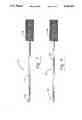
- This illustrative embodiment of the novel cervical continuous suction punch 80includes an elongate neck 82 having a pair of shearing members collectively denoted 84 at the distal end thereof.
- Shearing members 84are known in larger punch tools of the type used in conventional, i.e., non-arthroscopic surgery, and thus their construction need not be described.
- a novel handle means 86 in the form of a pair of handle members 88 and 90is integrally formed with neck 82 at the proximal end thereof and said handle members depend therefrom; the members are pivotally mounted about pivot point 89, and member 90 has a thumb-receiving loop 91.
- a strip 92 of spring steel or other suitable materialbiases handle members 88 and 90 apart from one another as indicated by arrow 93, i.e., the physician must overcome the bias to squeeze said handle members toward one another.
- Shear members 84are spaced apart from one another when punch 10 is in repose and ultimately converge toward one another when said handle members are squeezed; a diverging motion precedes the converging motion, but, again, the particular operation of the shearing members is well known and need not be described here.
- a coil spring 94 or other suitable bias meansis employed to urge the handle members 88 and 90 toward one another as indicated by converging arrows 95; thus, spring steel member 92 and coil spring member 94 are first and second bias means, respectively, that oppose one another.
- the strength of the opposing bias meansis substantially equal. This unique arrangement of parts removes play from the handle means 86 and insures that the handle members 88 and 90 will always return to their respective positions of repose when said handle members are released.
- a bore 96is formed in neck 82 and provides fluid communication between shears 84 and suction port 98 at the proximal end of punch tool 80. Bore 96 extends into port 98 as shown; port 98 provides a mounting means to which a first end of a cannula, not shown, or other suitable flexible tube means is detachably secured when the novel punch 80 is in use. The second end of the cannula is detachably secured to an unillustrated collection receptacle that is in fluid communication with an undepicted source of negative pressure.
- the site of the surgical procedureis irrigated during the nucleus-shearing process by causing irrigation fluid to flow into water port 44 in main sheath 30; the inside diameter of the main sheath is sufficient to receive neck 82 of punch tool 80 and to allow sufficient space thereabout to allow the irrigation fluid to flow freely to the surgical site.
- releasing the squeezing motion imparted to handle members 86 and 88opens the shears and releases the excised pieces into the irrigation fluid.
- Suitable meansare provided to permit the physician to control the amount of negative pressure supplied to port 98 and thus the flow rate of irrigation fluid and surgical debris flowing therethrough in the direction of arrow 100.
- neck 82through the bore of main sheath 30 is the only insertion needed to complete the entire debulking procedure.
- Irrigation fluidis introduced through water port 44 throughout the entire debulking procedure, and the suction applied to port 98 is similarly continuous throughout said procedure.
- Neck 82is preferably about 105 mm in length, exclusive of handle 86; said handle 86 has a length, measured from the neck 82 to the lowermost end of handle member 88, of about 85 mm.
- the outside diameter of neck 82is 2.5 mm, and the length of the movable part of the shear members 84 is 4 mm.
- FIG. 7depicts a cervical osteotone 110 that may also be inserted through main sheath 30 if chiseling of a vertebrae is required at any stage of the procedure.
- Osteotone 110includes a solid rod 112 having a chisel edge 114 formed in its leading end and a knurled base member 116 fixedly secured to its proximal end.
- the overall length of osteotone 110is 125 mm; the length of rod 112 is 105 mm.
- the lateral extent of chisel edge 114is 2.3 mm so that the tool is easily insertable through the bore of the main sheath.
- a novel cervical cureet or scoop member 120is depicted in FIG. 8; its rod part 122 and knurled base 124 have the same dimensions as the corresponding parts of the osteotone of FIG. 7.
- a scoop means 126is formed in the leading end of rod 122; it has the same construction as a conventional scoop means of the type used in non-arthroscopic surgery, but is only 2.2 mm in length. Cureet 120 is employed to scoop up the bone fragments created by bone chisel 110.
- the punch tool 130 of FIG. 9is like the tool of FIG. 6 in all respects except that it lacks suction port 98 and thus does not perform continuous vacuuming of the surgical site. It is suitable for use where the amount of debulking is limited.
- Neck 132 thereofis 105 mm in length, has an outside diameter of 2.4 mm, but has no bore formed therein; shear members 84 and the rest of the parts are similar to the parts of the punch shown in FIG. 6, as indicated by the common reference numerals.
- the cureet 140 of FIG. 10has a construction like that of the punch tool of FIG. 9, but it has a distal end with scoop means 142 that is activated by squeezing handles 88 and 90. Its neck 148 is also 105 mm in length and 2.4 mm in outside diameter and it can also be inserted through the bore of main sheath 30.
- the dimensions disclosed hereinare believed to be quite critical although small deviations therefrom still fall within the scope of this important invention.
- the dimensionsallow cervical discectomy to be performed by arthroscopic instruments.
- the inside and outside diameters of the dilator tubes and the outside diameters of the members insertable through the main sheath 30are critical because they enable the arthroscopic procedures disclosed herein.
Landscapes
- Health & Medical Sciences (AREA)
- Surgery (AREA)
- Life Sciences & Earth Sciences (AREA)
- Public Health (AREA)
- Nuclear Medicine, Radiotherapy & Molecular Imaging (AREA)
- Engineering & Computer Science (AREA)
- Biomedical Technology (AREA)
- Heart & Thoracic Surgery (AREA)
- Medical Informatics (AREA)
- Molecular Biology (AREA)
- Animal Behavior & Ethology (AREA)
- General Health & Medical Sciences (AREA)
- Veterinary Medicine (AREA)
- Orthopedic Medicine & Surgery (AREA)
- Dentistry (AREA)
- Oral & Maxillofacial Surgery (AREA)
- Pathology (AREA)
- Surgical Instruments (AREA)
- Massaging Devices (AREA)
- Orthopedics, Nursing, And Contraception (AREA)
- Paper (AREA)
- Pharmaceuticals Containing Other Organic And Inorganic Compounds (AREA)
- Pyrane Compounds (AREA)
- Media Introduction/Drainage Providing Device (AREA)
- Radiation-Therapy Devices (AREA)
- Prostheses (AREA)
Abstract
Description
Claims (3)
Priority Applications (12)
| Application Number | Priority Date | Filing Date | Title |
|---|---|---|---|
| US07/758,013US5269797A (en) | 1991-09-12 | 1991-09-12 | Cervical discectomy instruments |
| RU94016166ARU2121813C1 (en) | 1991-09-12 | 1992-09-14 | Dissection instruments for operations on neck |
| AT92920314TATE210407T1 (en) | 1991-09-12 | 1992-09-14 | INSTRUMENT FOR PROCESSING CERVICAL DISCS |
| AU26598/92AAU663338B2 (en) | 1991-09-12 | 1992-09-14 | Cervical discectomy instruments |
| DE69233382TDE69233382T2 (en) | 1991-09-12 | 1992-09-14 | Dissectectomy instruments for the spine |
| EP01105835AEP1101471B1 (en) | 1991-09-12 | 1992-09-14 | Cervical discectomy instruments |
| DE69232289TDE69232289T2 (en) | 1991-09-12 | 1992-09-14 | INSTRUMENT FOR MACHINING CERVICAL DISCS |
| CA002118811ACA2118811A1 (en) | 1991-09-12 | 1992-09-14 | Cervical discectomy instruments |
| JP50552193AJPH07502419A (en) | 1991-09-12 | 1992-09-14 | groin discectomy instrument |
| PCT/US1992/007735WO1993004652A1 (en) | 1991-09-12 | 1992-09-14 | Cervical dissectomy instruments |
| EP92920314AEP0603313B1 (en) | 1991-09-12 | 1992-09-14 | Cervical discectomy instruments |
| US08/108,036US5472426A (en) | 1991-09-12 | 1993-08-17 | Cervical discectomy instruments |
Applications Claiming Priority (1)
| Application Number | Priority Date | Filing Date | Title |
|---|---|---|---|
| US07/758,013US5269797A (en) | 1991-09-12 | 1991-09-12 | Cervical discectomy instruments |
Related Child Applications (1)
| Application Number | Title | Priority Date | Filing Date |
|---|---|---|---|
| US08/108,036Continuation-In-PartUS5472426A (en) | 1991-09-12 | 1993-08-17 | Cervical discectomy instruments |
Publications (1)
| Publication Number | Publication Date |
|---|---|
| US5269797Atrue US5269797A (en) | 1993-12-14 |
Family
ID=25050117
Family Applications (2)
| Application Number | Title | Priority Date | Filing Date |
|---|---|---|---|
| US07/758,013Expired - LifetimeUS5269797A (en) | 1991-09-12 | 1991-09-12 | Cervical discectomy instruments |
| US08/108,036Expired - LifetimeUS5472426A (en) | 1991-09-12 | 1993-08-17 | Cervical discectomy instruments |
Family Applications After (1)
| Application Number | Title | Priority Date | Filing Date |
|---|---|---|---|
| US08/108,036Expired - LifetimeUS5472426A (en) | 1991-09-12 | 1993-08-17 | Cervical discectomy instruments |
Country Status (9)
| Country | Link |
|---|---|
| US (2) | US5269797A (en) |
| EP (2) | EP1101471B1 (en) |
| JP (1) | JPH07502419A (en) |
| AT (1) | ATE210407T1 (en) |
| AU (1) | AU663338B2 (en) |
| CA (1) | CA2118811A1 (en) |
| DE (2) | DE69232289T2 (en) |
| RU (1) | RU2121813C1 (en) |
| WO (1) | WO1993004652A1 (en) |
Cited By (64)
| Publication number | Priority date | Publication date | Assignee | Title |
|---|---|---|---|---|
| US5643229A (en)* | 1994-07-22 | 1997-07-01 | Sinaiko; Edwin S. | Suction tube apparatus |
| US5693011A (en)* | 1995-04-27 | 1997-12-02 | Surgical Dynamics, Inc. | Surgical suction cutting instrument |
| US5693064A (en)* | 1994-11-04 | 1997-12-02 | Arnold; James E. | Dermal punch for hair transplantation and methods |
| US5851214A (en)* | 1994-10-07 | 1998-12-22 | United States Surgical Corporation | Surgical instrument useful for endoscopic procedures |
| US5873886A (en)* | 1995-04-04 | 1999-02-23 | United States Surgical Corporation | Surgical cutting apparatus |
| US5879365A (en)* | 1995-04-04 | 1999-03-09 | United States Surgical Corporation | Surgical cutting apparatus |
| US5938685A (en)* | 1997-09-05 | 1999-08-17 | Boston Scientific Corporation | Locking handle for surgical instruments |
| US5989196A (en)* | 1994-10-31 | 1999-11-23 | Boston Scientific Corporation | Biopsy needle |
| US6142955A (en) | 1997-09-19 | 2000-11-07 | United States Surgical Corporation | Biopsy apparatus and method |
| US6214010B1 (en)* | 1999-11-04 | 2001-04-10 | Thompson Surgical Instruments, Inc. | Rongeur surgical instrument |
| US20040158258A1 (en)* | 2003-02-12 | 2004-08-12 | Bonati Alfred O. | Method for removing orthopaedic hardware |
| US6793656B1 (en) | 1992-03-17 | 2004-09-21 | Sdgi Holdings, Inc. | Systems and methods for fixation of adjacent vertebrae |
| USD498300S1 (en) | 2002-01-18 | 2004-11-09 | Karl Storz Gmbh & Co. Kg | Circular punch |
| US6860860B2 (en) | 2000-11-27 | 2005-03-01 | Tyco Healthcare Group, Lp | Tissue sampling and removal apparatus and method |
| USD505725S1 (en)* | 2002-01-18 | 2005-05-31 | Karl Storz Gmbh & Co. Kg | Handle for a circular punch |
| US20050149086A1 (en)* | 2003-11-20 | 2005-07-07 | Osseus, Llc | Method and device for cutting surgical wire or cable |
| US20060241566A1 (en)* | 2005-04-11 | 2006-10-26 | Orthox, Llc | Nucleus Extraction from Spine Intervertebral Disc |
| US20070055259A1 (en)* | 2005-08-17 | 2007-03-08 | Norton Britt K | Apparatus and methods for removal of intervertebral disc tissues |
| US7189207B2 (en) | 2000-09-11 | 2007-03-13 | Tyco Healthcare Group Lp | Biopsy system having a single use loading unit operable with a trocar driver, a knife driver and firing module |
| US20070162062A1 (en)* | 2005-12-08 | 2007-07-12 | Norton Britt K | Reciprocating apparatus and methods for removal of intervertebral disc tissues |
| US20070265633A1 (en)* | 2006-05-11 | 2007-11-15 | Moon Jon K | Implement and method to extract nucleus from spine intervertebral disc |
| US20080234690A1 (en)* | 2007-03-23 | 2008-09-25 | Depuy Spine, Inc. | Volume measuring intervertebral tool system and method |
| US7465304B1 (en) | 2003-04-14 | 2008-12-16 | Spine Design, Inc. | Anterior cervical facet discectomy surgery kit and method for its use |
| US7713301B2 (en) | 1994-05-06 | 2010-05-11 | Disc Dynamics, Inc. | Intervertebral disc prosthesis |
| US20110190801A1 (en)* | 2010-02-04 | 2011-08-04 | Mark Joseph L | Tissue removal device |
| US20110190802A1 (en)* | 2010-02-04 | 2011-08-04 | Mark Joseph L | Tissue removal device with tissue grip |
| US8092536B2 (en) | 2006-05-24 | 2012-01-10 | Disc Dynamics, Inc. | Retention structure for in situ formation of an intervertebral prosthesis |
| EP1773438A4 (en)* | 2004-08-03 | 2012-04-11 | Interventional Spine Inc | TELESCOPIC PERCUTANE TISSUE EXPANSION SYSTEMS |
| US20120197320A1 (en)* | 2011-01-28 | 2012-08-02 | Laser Spine Surgical Center, LLC | Foraminoplasty Device |
| US9387313B2 (en) | 2004-08-03 | 2016-07-12 | Interventional Spine, Inc. | Telescopic percutaneous tissue dilation systems and related methods |
| US9522070B2 (en) | 2013-03-07 | 2016-12-20 | Interventional Spine, Inc. | Intervertebral implant |
| US9839530B2 (en) | 2007-06-26 | 2017-12-12 | DePuy Synthes Products, Inc. | Highly lordosed fusion cage |
| US9883951B2 (en) | 2012-08-30 | 2018-02-06 | Interventional Spine, Inc. | Artificial disc |
| US9895236B2 (en) | 2010-06-24 | 2018-02-20 | DePuy Synthes Products, Inc. | Enhanced cage insertion assembly |
| US9913727B2 (en) | 2015-07-02 | 2018-03-13 | Medos International Sarl | Expandable implant |
| US9931223B2 (en) | 2008-04-05 | 2018-04-03 | DePuy Synthes Products, Inc. | Expandable intervertebral implant |
| US9993349B2 (en) | 2002-06-27 | 2018-06-12 | DePuy Synthes Products, Inc. | Intervertebral disc |
| US10058433B2 (en) | 2012-07-26 | 2018-08-28 | DePuy Synthes Products, Inc. | Expandable implant |
| US10390963B2 (en) | 2006-12-07 | 2019-08-27 | DePuy Synthes Products, Inc. | Intervertebral implant |
| US10398563B2 (en) | 2017-05-08 | 2019-09-03 | Medos International Sarl | Expandable cage |
| US10433977B2 (en) | 2008-01-17 | 2019-10-08 | DePuy Synthes Products, Inc. | Expandable intervertebral implant and associated method of manufacturing the same |
| US10500062B2 (en) | 2009-12-10 | 2019-12-10 | DePuy Synthes Products, Inc. | Bellows-like expandable interbody fusion cage |
| US10537436B2 (en) | 2016-11-01 | 2020-01-21 | DePuy Synthes Products, Inc. | Curved expandable cage |
| US10548741B2 (en) | 2010-06-29 | 2020-02-04 | DePuy Synthes Products, Inc. | Distractible intervertebral implant |
| US10813772B2 (en) | 2013-03-11 | 2020-10-27 | DePuy Synthes Products, Inc. | Method and apparatus for minimally invasive insertion of intervertebral implants |
| US10888433B2 (en) | 2016-12-14 | 2021-01-12 | DePuy Synthes Products, Inc. | Intervertebral implant inserter and related methods |
| US10940016B2 (en) | 2017-07-05 | 2021-03-09 | Medos International Sarl | Expandable intervertebral fusion cage |
| US11344424B2 (en) | 2017-06-14 | 2022-05-31 | Medos International Sarl | Expandable intervertebral implant and related methods |
| US11426290B2 (en) | 2015-03-06 | 2022-08-30 | DePuy Synthes Products, Inc. | Expandable intervertebral implant, system, kit and method |
| US11426286B2 (en) | 2020-03-06 | 2022-08-30 | Eit Emerging Implant Technologies Gmbh | Expandable intervertebral implant |
| US11446156B2 (en) | 2018-10-25 | 2022-09-20 | Medos International Sarl | Expandable intervertebral implant, inserter instrument, and related methods |
| US11452607B2 (en) | 2010-10-11 | 2022-09-27 | DePuy Synthes Products, Inc. | Expandable interspinous process spacer implant |
| WO2022231613A1 (en)* | 2021-04-30 | 2022-11-03 | Aok Innovations, Llc | Body cavity access device |
| US11510788B2 (en) | 2016-06-28 | 2022-11-29 | Eit Emerging Implant Technologies Gmbh | Expandable, angularly adjustable intervertebral cages |
| US20230046955A1 (en)* | 2021-08-12 | 2023-02-16 | Olympus Medical Systems Corp. | Treatment instrument |
| US11596523B2 (en) | 2016-06-28 | 2023-03-07 | Eit Emerging Implant Technologies Gmbh | Expandable and angularly adjustable articulating intervertebral cages |
| US11612491B2 (en) | 2009-03-30 | 2023-03-28 | DePuy Synthes Products, Inc. | Zero profile spinal fusion cage |
| US11752009B2 (en) | 2021-04-06 | 2023-09-12 | Medos International Sarl | Expandable intervertebral fusion cage |
| US11850160B2 (en) | 2021-03-26 | 2023-12-26 | Medos International Sarl | Expandable lordotic intervertebral fusion cage |
| US11911287B2 (en) | 2010-06-24 | 2024-02-27 | DePuy Synthes Products, Inc. | Lateral spondylolisthesis reduction cage |
| US11963692B2 (en) | 2021-04-30 | 2024-04-23 | Aok Innovations, Llc | Body cavity access device |
| USRE49973E1 (en) | 2013-02-28 | 2024-05-21 | DePuy Synthes Products, Inc. | Expandable intervertebral implant, system, kit and method |
| US12090064B2 (en) | 2022-03-01 | 2024-09-17 | Medos International Sarl | Stabilization members for expandable intervertebral implants, and related systems and methods |
| US12440346B2 (en) | 2023-03-31 | 2025-10-14 | DePuy Synthes Products, Inc. | Expandable intervertebral implant |
Families Citing this family (187)
| Publication number | Priority date | Publication date | Assignee | Title |
|---|---|---|---|---|
| FR2714285B1 (en)* | 1993-12-24 | 1996-03-15 | Impact | Device for performing a percutaneous nucleotomy. |
| DE19515626C2 (en)* | 1995-04-28 | 2000-04-06 | Wolf Gmbh Richard | Instrument for positioning at least one working sleeve |
| US5817034A (en)* | 1995-09-08 | 1998-10-06 | United States Surgical Corporation | Apparatus and method for removing tissue |
| US5857982A (en)* | 1995-09-08 | 1999-01-12 | United States Surgical Corporation | Apparatus and method for removing tissue |
| US7198598B2 (en)* | 1996-03-22 | 2007-04-03 | Warsaw Orthopedic, Inc. | Devices and methods for percutaneous surgery |
| US5792044A (en)* | 1996-03-22 | 1998-08-11 | Danek Medical, Inc. | Devices and methods for percutaneous surgery |
| US6679833B2 (en) | 1996-03-22 | 2004-01-20 | Sdgi Holdings, Inc. | Devices and methods for percutaneous surgery |
| DE19780707C2 (en)* | 1996-03-22 | 2002-09-12 | Sdgi Holdings Inc | Percutaneous surgery device |
| DE69735146T2 (en)* | 1996-05-09 | 2006-09-28 | Olympus Corporation | Surgical tool for holding a cavity |
| US6733496B2 (en) | 2001-06-06 | 2004-05-11 | Oratec Interventions, Inc. | Intervertebral disc device employing flexible probe |
| US7069087B2 (en) | 2000-02-25 | 2006-06-27 | Oratec Interventions, Inc. | Apparatus and method for accessing and performing a function within an intervertebral disc |
| US6832997B2 (en) | 2001-06-06 | 2004-12-21 | Oratec Interventions, Inc. | Electromagnetic energy delivery intervertebral disc treatment devices |
| US6726685B2 (en)* | 2001-06-06 | 2004-04-27 | Oratec Interventions, Inc. | Intervertebral disc device employing looped probe |
| US6126682A (en) | 1996-08-13 | 2000-10-03 | Oratec Interventions, Inc. | Method for treating annular fissures in intervertebral discs |
| TW375522B (en)* | 1996-10-24 | 1999-12-01 | Danek Medical Inc | Devices for percutaneous surgery under direct visualization and through an elongated cannula |
| US6068630A (en)* | 1997-01-02 | 2000-05-30 | St. Francis Medical Technologies, Inc. | Spine distraction implant |
| US5976146A (en)* | 1997-07-11 | 1999-11-02 | Olympus Optical Co., Ltd. | Surgical operation system and method of securing working space for surgical operation in body |
| JPH1176247A (en)* | 1997-07-11 | 1999-03-23 | Olympus Optical Co Ltd | Surgical operation system |
| US6175758B1 (en) | 1997-07-15 | 2001-01-16 | Parviz Kambin | Method for percutaneous arthroscopic disc removal, bone biopsy and fixation of the vertebrae |
| US6383145B1 (en) | 1997-09-12 | 2002-05-07 | Imagyn Medical Technologies California, Inc. | Incisional breast biopsy device |
| US6551253B2 (en) | 1997-09-12 | 2003-04-22 | Imagyn Medical Technologies | Incisional breast biopsy device |
| EP1063931A2 (en) | 1998-03-19 | 2001-01-03 | Oratec Interventions, Inc. | Catheter for delivery of energy to a surgical site |
| US6187000B1 (en) | 1998-08-20 | 2001-02-13 | Endius Incorporated | Cannula for receiving surgical instruments |
| US7799036B2 (en) | 1998-08-20 | 2010-09-21 | Zimmer Spine, Inc. | Method and apparatus for securing vertebrae |
| US7641670B2 (en) | 1998-08-20 | 2010-01-05 | Zimmer Spine, Inc. | Cannula for receiving surgical instruments |
| EP1146816B1 (en) | 1998-12-23 | 2005-10-12 | Nuvasive Inc. | Nerve surveillance cannulae systems |
| US7449019B2 (en) | 1999-01-25 | 2008-11-11 | Smith & Nephew, Inc. | Intervertebral decompression |
| US20050203334A1 (en)* | 1999-01-26 | 2005-09-15 | Lonky Neal M. | Vacuum instrument for laparotomy procedures |
| US6641575B1 (en)* | 1999-01-26 | 2003-11-04 | Neal M. Lonky | Surgical vacuum instrument for retracting, extracting, and manipulating tissue |
| CA2363254C (en) | 1999-03-07 | 2009-05-05 | Discure Ltd. | Method and apparatus for computerized surgery |
| US6159179A (en)* | 1999-03-12 | 2000-12-12 | Simonson; Robert E. | Cannula and sizing and insertion method |
| JP2003501198A (en)* | 1999-06-16 | 2003-01-14 | トマス ホークラント, | Method and apparatus for decompressing a herniated disc |
| US6575899B1 (en) | 1999-10-20 | 2003-06-10 | Sdgi Holdings, Inc. | Methods and instruments for endoscopic interbody surgical techniques |
| WO2001037728A1 (en) | 1999-11-24 | 2001-05-31 | Nuvasive, Inc. | Electromyography system |
| US8409214B2 (en)* | 2009-01-22 | 2013-04-02 | Meditech Development Incorporated | Portable regulated vacuum pump for medical procedures |
| US8915894B1 (en) | 2000-01-24 | 2014-12-23 | Meditech Development Incorporated | Vacuum cup for delivery of agents during vacuum treatment |
| DE10003050C2 (en)* | 2000-01-25 | 2002-03-07 | Copf Jun | Surgical dilatation instrument and spacer for use with such |
| AU2001280476B2 (en) | 2000-06-30 | 2005-11-24 | Stephen Ritland | Polyaxial connection device and method |
| US7056321B2 (en) | 2000-08-01 | 2006-06-06 | Endius, Incorporated | Method of securing vertebrae |
| US7985247B2 (en) | 2000-08-01 | 2011-07-26 | Zimmer Spine, Inc. | Methods and apparatuses for treating the spine through an access device |
| US6692434B2 (en) | 2000-09-29 | 2004-02-17 | Stephen Ritland | Method and device for retractor for microsurgical intermuscular lumbar arthrodesis |
| US7166073B2 (en) | 2000-09-29 | 2007-01-23 | Stephen Ritland | Method and device for microsurgical intermuscular spinal surgery |
| CA2428546A1 (en)* | 2000-11-13 | 2002-05-16 | Frank H. Boehm, Jr. | Device and method for lumbar interbody fusion |
| WO2002060330A1 (en)* | 2001-01-29 | 2002-08-08 | Stephen Ritland | Retractor and method for spinal pedicle screw placement |
| US6929606B2 (en) | 2001-01-29 | 2005-08-16 | Depuy Spine, Inc. | Retractor and method for spinal pedicle screw placement |
| US6638276B2 (en) | 2001-06-06 | 2003-10-28 | Oratec Interventions, Inc. | Intervertebral disc device employing prebent sheath |
| EP1417000B1 (en) | 2001-07-11 | 2018-07-11 | Nuvasive, Inc. | System for determining nerve proximity during surgery |
| JP2005503857A (en) | 2001-09-25 | 2005-02-10 | ヌバシブ, インコーポレイテッド | Systems and methods for performing surgical procedures and surgical diagnosis |
| DE60238997D1 (en) | 2001-09-28 | 2011-03-03 | Stephen Ritland | CHROME OR HOOKS |
| US7824410B2 (en) | 2001-10-30 | 2010-11-02 | Depuy Spine, Inc. | Instruments and methods for minimally invasive spine surgery |
| US7008431B2 (en)* | 2001-10-30 | 2006-03-07 | Depuy Spine, Inc. | Configured and sized cannula |
| US6916330B2 (en)* | 2001-10-30 | 2005-07-12 | Depuy Spine, Inc. | Non cannulated dilators |
| ATE476930T1 (en)* | 2002-02-20 | 2010-08-15 | Stephen Ritland | DEVICE FOR CONNECTING HAND SCREWS |
| US20030187431A1 (en)* | 2002-03-29 | 2003-10-02 | Simonson Robert E. | Apparatus and method for targeting for surgical procedures |
| US6966910B2 (en) | 2002-04-05 | 2005-11-22 | Stephen Ritland | Dynamic fixation device and method of use |
| ATE552789T1 (en) | 2002-05-08 | 2012-04-15 | Stephen Ritland | DYNAMIC FIXATION DEVICE |
| US7004947B2 (en)* | 2002-06-24 | 2006-02-28 | Endius Incorporated | Surgical instrument for moving vertebrae |
| US7582058B1 (en) | 2002-06-26 | 2009-09-01 | Nuvasive, Inc. | Surgical access system and related methods |
| US9259144B2 (en)* | 2002-07-11 | 2016-02-16 | Nuvasive, Inc. | Surgical access system and related methods |
| US6648888B1 (en) | 2002-09-06 | 2003-11-18 | Endius Incorporated | Surgical instrument for moving a vertebra |
| US7074226B2 (en)* | 2002-09-19 | 2006-07-11 | Sdgi Holdings, Inc. | Oval dilator and retractor set and method |
| US8137284B2 (en) | 2002-10-08 | 2012-03-20 | Nuvasive, Inc. | Surgical access system and related methods |
| WO2004039235A2 (en)* | 2002-10-25 | 2004-05-13 | Endius Incorporated | Apparatus and methods for shielding body structures during surgery |
| US20040106997A1 (en)* | 2002-11-01 | 2004-06-03 | Lieberson Robert E. | Apparatus and method for creating a surgical channel |
| US7691057B2 (en) | 2003-01-16 | 2010-04-06 | Nuvasive, Inc. | Surgical access system and related methods |
| US20040158257A1 (en)* | 2003-02-12 | 2004-08-12 | Bonati Alfred O. | Extractor tube for removing orthopaedic hardware |
| EP1596738A4 (en)* | 2003-02-25 | 2010-01-20 | Stephen Ritland | Adjustable rod and connector device and method of use |
| US7819801B2 (en) | 2003-02-27 | 2010-10-26 | Nuvasive, Inc. | Surgical access system and related methods |
| US7641659B2 (en)* | 2003-03-13 | 2010-01-05 | Zimmer Spine, Inc. | Spinal access instrument |
| US7645232B2 (en) | 2003-05-16 | 2010-01-12 | Zimmer Spine, Inc. | Access device for minimally invasive surgery |
| WO2004110247A2 (en) | 2003-05-22 | 2004-12-23 | Stephen Ritland | Intermuscular guide for retractor insertion and method of use |
| US7811303B2 (en)* | 2003-08-26 | 2010-10-12 | Medicine Lodge Inc | Bodily tissue dilation systems and methods |
| US7905840B2 (en)* | 2003-10-17 | 2011-03-15 | Nuvasive, Inc. | Surgical access system and related methods |
| JP4463819B2 (en) | 2003-09-25 | 2010-05-19 | ヌヴァシヴ インコーポレイテッド | Surgical access system |
| US7655012B2 (en) | 2003-10-02 | 2010-02-02 | Zimmer Spine, Inc. | Methods and apparatuses for minimally invasive replacement of intervertebral discs |
| US20050090899A1 (en)* | 2003-10-24 | 2005-04-28 | Dipoto Gene | Methods and apparatuses for treating the spine through an access device |
| US20050090822A1 (en)* | 2003-10-24 | 2005-04-28 | Dipoto Gene | Methods and apparatus for stabilizing the spine through an access device |
| US7731737B2 (en)* | 2003-10-24 | 2010-06-08 | Zimmer Spine, Inc. | Methods and apparatuses for fixation of the spine through an access device |
| US7588575B2 (en) | 2003-10-21 | 2009-09-15 | Innovative Spinal Technologies | Extension for use with stabilization systems for internal structures |
| US8038611B2 (en) | 2003-12-18 | 2011-10-18 | Depuy Spine, Inc. | Surgical methods and surgical kits |
| US20050137600A1 (en)* | 2003-12-23 | 2005-06-23 | Jacobs Andrew M. | Articular cartilage repair implant delivery device and method of use |
| DE102004006521A1 (en)* | 2004-02-10 | 2005-09-08 | Horst Drs. Dekkers | Set of surgical instruments for spine surgery |
| US7909843B2 (en) | 2004-06-30 | 2011-03-22 | Thompson Surgical Instruments, Inc. | Elongateable surgical port and dilator |
| US20060004398A1 (en)* | 2004-07-02 | 2006-01-05 | Binder Lawrence J Jr | Sequential dilator system |
| US7434325B2 (en) | 2004-07-26 | 2008-10-14 | Warsaw Orthopedic, Inc. | Systems and methods for determining optimal retractor length in minimally invasive procedures |
| US20060052812A1 (en)* | 2004-09-07 | 2006-03-09 | Michael Winer | Tool for preparing a surgical site for an access device |
| WO2006031939A1 (en)* | 2004-09-14 | 2006-03-23 | Uromedica, Inc. | Implantation tool for adjustable implantable genitourinary device |
| US7455639B2 (en) | 2004-09-20 | 2008-11-25 | Stephen Ritland | Opposing parallel bladed retractor and method of use |
| US7666189B2 (en)* | 2004-09-29 | 2010-02-23 | Synthes Usa, Llc | Less invasive surgical system and methods |
| WO2006042241A2 (en) | 2004-10-08 | 2006-04-20 | Nuvasive, Inc. | Surgical access system and related methods |
| EP1807012B1 (en)* | 2004-10-25 | 2016-07-06 | Lanx, LLC | Nterspinous distraction devices |
| US8241330B2 (en) | 2007-01-11 | 2012-08-14 | Lanx, Inc. | Spinous process implants and associated methods |
| US9055981B2 (en) | 2004-10-25 | 2015-06-16 | Lanx, Inc. | Spinal implants and methods |
| US7594888B2 (en)* | 2004-10-29 | 2009-09-29 | Depuy Spine, Inc. | Expandable ports and methods for minimally invasive surgery |
| US20060217664A1 (en)* | 2004-11-15 | 2006-09-28 | Hattler Brack G | Telescoping vascular dilator |
| US7569061B2 (en) | 2004-11-16 | 2009-08-04 | Innovative Spinal Technologies, Inc. | Off-axis anchor guidance system |
| US20060224044A1 (en)* | 2005-03-31 | 2006-10-05 | Depuy Spine, Inc. | Surgical retractors and methods of use |
| US7427264B2 (en)* | 2005-04-22 | 2008-09-23 | Warsaw Orthopedic, Inc. | Instruments and methods for selective tissue retraction through a retractor sleeve |
| JP4988735B2 (en) | 2005-07-19 | 2012-08-01 | リットランド、ステファン | Rod extension for elongating fusion structures |
| WO2007038429A1 (en) | 2005-09-27 | 2007-04-05 | Endius, Inc. | Methods and apparatuses for stabilizing the spine through an access device |
| US8066730B2 (en)* | 2005-11-14 | 2011-11-29 | Scapa Flow, Llc | Medical dilator system or dilator device |
| US7758501B2 (en)* | 2006-01-04 | 2010-07-20 | Depuy Spine, Inc. | Surgical reactors and methods of minimally invasive surgery |
| US7918792B2 (en)* | 2006-01-04 | 2011-04-05 | Depuy Spine, Inc. | Surgical retractor for use with minimally invasive spinal stabilization systems and methods of minimally invasive surgery |
| US7981031B2 (en) | 2006-01-04 | 2011-07-19 | Depuy Spine, Inc. | Surgical access devices and methods of minimally invasive surgery |
| US7955257B2 (en)* | 2006-01-05 | 2011-06-07 | Depuy Spine, Inc. | Non-rigid surgical retractor |
| US7842038B2 (en) | 2006-05-04 | 2010-11-30 | Warsaw Orthopedic, Inc. | Method for using retractable stylet and cannula combination to form an opening in bone |
| US8167899B2 (en)* | 2006-05-04 | 2012-05-01 | Warsaw Orthopedic, Inc. | Retractable stylet and cannula combination |
| US7959564B2 (en) | 2006-07-08 | 2011-06-14 | Stephen Ritland | Pedicle seeker and retractor, and methods of use |
| USD631962S1 (en) | 2006-11-14 | 2011-02-01 | Scapa Flow, Llc | Medical dilator |
| US12290277B2 (en) | 2007-01-02 | 2025-05-06 | Aquabeam, Llc | Tissue resection with pressure sensing |
| US9232959B2 (en) | 2007-01-02 | 2016-01-12 | Aquabeam, Llc | Multi fluid tissue resection methods and devices |
| US9265532B2 (en) | 2007-01-11 | 2016-02-23 | Lanx, Inc. | Interspinous implants and methods |
| US9247968B2 (en) | 2007-01-11 | 2016-02-02 | Lanx, Inc. | Spinous process implants and associated methods |
| US20080255651A1 (en)* | 2007-04-12 | 2008-10-16 | Medtronic Vascular, Inc. | Telescoping Stability Sheath and Method of Use |
| BRPI0818608A2 (en) | 2007-10-05 | 2015-04-22 | Synthes Gmbh | Sequential directional dilatation system for dilating from a nerve of a patient's anatomy, and method for forming an access opening through a psoas muscle to a patient's spine using a dilatation system |
| ES2769535T3 (en) | 2008-03-06 | 2020-06-26 | Aquabeam Llc | Tissue ablation and cauterization with optical energy carried in a fluid stream |
| US20100023006A1 (en)* | 2008-07-23 | 2010-01-28 | Ellman Alan G | RF intervertebral disc surgical system |
| AU2009329873A1 (en) | 2008-12-26 | 2011-11-03 | Scott Spann | Minimally-invasive retroperitoneal lateral approach for spinal surgery |
| US8562610B2 (en) | 2010-07-13 | 2013-10-22 | Warsaw Orthopedic, Inc. | Compliant device and method for cutting an intervertebral disc |
| US9155503B2 (en) | 2010-10-27 | 2015-10-13 | Cadwell Labs | Apparatus, system, and method for mapping the location of a nerve |
| US20120191079A1 (en) | 2011-01-20 | 2012-07-26 | Hansen Medical, Inc. | System and method for endoluminal and translumenal therapy |
| US9445825B2 (en) | 2011-02-10 | 2016-09-20 | Wright Medical Technology, Inc. | Expandable surgical device |
| US8790406B1 (en) | 2011-04-01 | 2014-07-29 | William D. Smith | Systems and methods for performing spine surgery |
| US8834507B2 (en) | 2011-05-17 | 2014-09-16 | Warsaw Orthopedic, Inc. | Dilation instruments and methods |
| CN103987326B (en) | 2011-08-19 | 2016-06-08 | 诺威适有限公司 | Surgical retractor system and method of use |
| US8753344B2 (en)* | 2011-09-23 | 2014-06-17 | Smith & Nephew, Inc. | Dynamic orthoscopic sensing |
| US11812923B2 (en) | 2011-10-07 | 2023-11-14 | Alan Villavicencio | Spinal fixation device |
| US9198765B1 (en) | 2011-10-31 | 2015-12-01 | Nuvasive, Inc. | Expandable spinal fusion implants and related methods |
| US9028522B1 (en) | 2011-11-15 | 2015-05-12 | Seaspine, Inc. | Tissue dilator and retractor system and method of use |
| EP3351196A1 (en) | 2012-02-29 | 2018-07-25 | Procept Biorobotics Corporation | Automated image-guided tissue resection and treatment |
| US9186444B2 (en) | 2012-05-07 | 2015-11-17 | Meditech Development Incorporated | Portable regulated pressure devices for medical procedures |
| US9295401B2 (en) | 2012-11-27 | 2016-03-29 | Cadwell Laboratories, Inc. | Neuromonitoring systems and methods |
| US10231867B2 (en) | 2013-01-18 | 2019-03-19 | Auris Health, Inc. | Method, apparatus and system for a water jet |
| US10098585B2 (en) | 2013-03-15 | 2018-10-16 | Cadwell Laboratories, Inc. | Neuromonitoring systems and methods |
| WO2014201165A1 (en) | 2013-06-11 | 2014-12-18 | Auris Surgical Robotics, Inc. | System for robotic assisted cataract surgery |
| US10426661B2 (en) | 2013-08-13 | 2019-10-01 | Auris Health, Inc. | Method and apparatus for laser assisted cataract surgery |
| US9788856B2 (en) | 2014-03-11 | 2017-10-17 | Stryker European Holdings I, Llc | Endoscopic surgical systems and methods |
| US10258228B2 (en)* | 2014-08-08 | 2019-04-16 | K2M, Inc. | Retraction devices, systems, and methods for minimally invasive spinal surgery |
| US10433793B1 (en) | 2015-03-27 | 2019-10-08 | Cadwell Laboratories, Inc. | Methods and systems for simultaneous review of brain activity and physical manifestations of users |
| US20160287279A1 (en) | 2015-04-01 | 2016-10-06 | Auris Surgical Robotics, Inc. | Microsurgical tool for robotic applications |
| US9949749B2 (en) | 2015-10-30 | 2018-04-24 | Auris Surgical Robotics, Inc. | Object capture with a basket |
| US10231793B2 (en) | 2015-10-30 | 2019-03-19 | Auris Health, Inc. | Object removal through a percutaneous suction tube |
| US9955986B2 (en) | 2015-10-30 | 2018-05-01 | Auris Surgical Robotics, Inc. | Basket apparatus |
| US10974027B2 (en) | 2016-07-29 | 2021-04-13 | Cephea Valve Technologies, Inc. | Combination steerable catheter and systems |
| US10933216B2 (en) | 2016-08-29 | 2021-03-02 | Cephea Valve Technologies, Inc. | Multilumen catheter |
| US11241297B2 (en) | 2016-12-12 | 2022-02-08 | Cadwell Laboratories, Inc. | System and method for high density electrode management |
| US9935395B1 (en) | 2017-01-23 | 2018-04-03 | Cadwell Laboratories, Inc. | Mass connection plate for electrical connectors |
| CN108934160B (en) | 2017-03-28 | 2021-08-31 | 奥瑞斯健康公司 | Shaft actuating handle |
| US10285574B2 (en) | 2017-04-07 | 2019-05-14 | Auris Health, Inc. | Superelastic medical instrument |
| EP3606400B1 (en) | 2017-04-07 | 2022-03-09 | Auris Health, Inc. | Patient introducer alignment |
| US11331091B2 (en)* | 2017-11-14 | 2022-05-17 | Endovision Co., Ltd. | Surgical instrument set for use during unilateral biportal endoscopy |
| US11517239B2 (en) | 2018-04-05 | 2022-12-06 | Cadwell Laboratories, Inc. | Systems and methods for processing and displaying electromyographic signals |
| US11596337B2 (en) | 2018-04-24 | 2023-03-07 | Cadwell Laboratories, Inc | Methods and systems for operating an intraoperative neurophysiological monitoring system in conjunction with electrocautery procedures |
| US11992339B2 (en) | 2018-05-04 | 2024-05-28 | Cadwell Laboratories, Inc. | Systems and methods for dynamic neurophysiological stimulation |
| US11253182B2 (en) | 2018-05-04 | 2022-02-22 | Cadwell Laboratories, Inc. | Apparatus and method for polyphasic multi-output constant-current and constant-voltage neurophysiological stimulation |
| JP7267309B2 (en) | 2018-06-07 | 2023-05-01 | オーリス ヘルス インコーポレイテッド | Robotic medical system with high-strength instruments |
| JP7391886B2 (en) | 2018-06-28 | 2023-12-05 | オーリス ヘルス インコーポレイテッド | Medical system incorporating pulley sharing |
| US11443649B2 (en) | 2018-06-29 | 2022-09-13 | Cadwell Laboratories, Inc. | Neurophysiological monitoring training simulator |
| WO2020036685A1 (en) | 2018-08-15 | 2020-02-20 | Auris Health, Inc. | Medical instruments for tissue cauterization |
| WO2020036686A1 (en) | 2018-08-17 | 2020-02-20 | Auris Health, Inc. | Bipolar medical instrument |
| US11185684B2 (en) | 2018-09-18 | 2021-11-30 | Cadwell Laboratories, Inc. | Minimally invasive two-dimensional grid electrode |
| CN112770689B (en) | 2018-09-26 | 2024-07-19 | 奥瑞斯健康公司 | Systems and instruments for suction and irrigation |
| US11576738B2 (en) | 2018-10-08 | 2023-02-14 | Auris Health, Inc. | Systems and instruments for tissue sealing |
| EP3873351B1 (en) | 2018-10-29 | 2023-09-20 | Stryker Corporation | System of performing spine surgery and maintaining a volume of fluid at a surgical site |
| US11517245B2 (en) | 2018-10-30 | 2022-12-06 | Cadwell Laboratories, Inc. | Method and system for data synchronization |
| US11471087B2 (en) | 2018-11-09 | 2022-10-18 | Cadwell Laboratories, Inc. | Integrity verification system for testing high channel count neuromonitoring recording equipment |
| US11317841B2 (en) | 2018-11-14 | 2022-05-03 | Cadwell Laboratories, Inc. | Method and system for electrode verification |
| US11529107B2 (en) | 2018-11-27 | 2022-12-20 | Cadwell Laboratories, Inc. | Methods for automatic generation of EEG montages |
| WO2020131529A1 (en) | 2018-12-20 | 2020-06-25 | Auris Health, Inc. | Shielding for wristed instruments |
| US11128076B2 (en) | 2019-01-21 | 2021-09-21 | Cadwell Laboratories, Inc. | Connector receptacle |
| EP3883492B1 (en) | 2019-01-25 | 2025-05-21 | Auris Health, Inc. | Vessel sealer with heating capabilities |
| EP3908201B1 (en) | 2019-03-25 | 2024-04-24 | Auris Health, Inc. | Instruments for medical stapling |
| CN114126529A (en) | 2019-06-25 | 2022-03-01 | 奥瑞斯健康公司 | Medical instrument including a wrist with hybrid redirecting surfaces |
| WO2020263629A1 (en) | 2019-06-27 | 2020-12-30 | Auris Health, Inc. | Systems and methods for a medical clip applier |
| WO2020263949A1 (en) | 2019-06-28 | 2020-12-30 | Auris Health, Inc. | Medical instruments including wrists with hybrid redirect surfaces |
| US11896330B2 (en) | 2019-08-15 | 2024-02-13 | Auris Health, Inc. | Robotic medical system having multiple medical instruments |
| US10959792B1 (en) | 2019-09-26 | 2021-03-30 | Auris Health, Inc. | Systems and methods for collision detection and avoidance |
| WO2021059100A1 (en) | 2019-09-26 | 2021-04-01 | Auris Health, Inc. | Systems and methods for collision avoidance using object models |
| US11737845B2 (en) | 2019-09-30 | 2023-08-29 | Auris Inc. | Medical instrument with a capstan |
| US11737835B2 (en) | 2019-10-29 | 2023-08-29 | Auris Health, Inc. | Braid-reinforced insulation sheath |
| CN114727850A (en) | 2019-11-21 | 2022-07-08 | 奥瑞斯健康公司 | Systems and methods for draping surgical systems |
| EP4084724A4 (en) | 2019-12-31 | 2023-12-27 | Auris Health, Inc. | ADVANCED BASKET DRIVE MODE |
| CN114901188A (en) | 2019-12-31 | 2022-08-12 | 奥瑞斯健康公司 | Dynamic pulley system |
| US12370002B2 (en) | 2020-03-30 | 2025-07-29 | Auris Health, Inc. | Workspace optimization for robotic surgery |
| CN115802975A (en) | 2020-06-29 | 2023-03-14 | 奥瑞斯健康公司 | System and method for detecting contact between a connecting rod and an external object |
| US11357586B2 (en) | 2020-06-30 | 2022-06-14 | Auris Health, Inc. | Systems and methods for saturated robotic movement |
| CN115734765A (en) | 2020-06-30 | 2023-03-03 | 奥瑞斯健康公司 | Robotic medical system with crash proximity indicator |
Citations (8)
| Publication number | Priority date | Publication date | Assignee | Title |
|---|---|---|---|---|
| US2112873A (en)* | 1936-11-07 | 1938-04-05 | Wright Jerauld | Tool |
| US2532141A (en)* | 1947-07-09 | 1950-11-28 | Eaton Mfg Co | Split ring expander |
| DE2457862A1 (en)* | 1973-12-06 | 1975-07-24 | David Marcos Halpern | SURGICAL BIOPSY INSTRUMENT |
| US3921640A (en)* | 1974-03-22 | 1975-11-25 | Int Paper Co | Disposable surgical instruments |
| US4499899A (en)* | 1983-01-21 | 1985-02-19 | Brimfield Precision, Inc. | Fiber-optic illuminated microsurgical scissors |
| US4712545A (en)* | 1984-04-05 | 1987-12-15 | Acufex Microsurgical, Inc. | Surgical instrument |
| US4881550A (en)* | 1987-02-18 | 1989-11-21 | Lutz Kothe | Medical instrument |
| US4990148A (en)* | 1989-01-13 | 1991-02-05 | Codman & Shurtleff, Inc. | Thin footplate rongeur |
Family Cites Families (33)
| Publication number | Priority date | Publication date | Assignee | Title |
|---|---|---|---|---|
| US473448A (en)* | 1892-04-26 | Lettee | ||
| GB843744A (en)* | 1957-10-17 | 1960-08-10 | Wilbur Raymond Koehn | Surgical apparatus incorporating a catheter tube |
| US3875938A (en)* | 1973-08-22 | 1975-04-08 | Eli K Mellor | Multi-mode cannulating apparatus |
| US4368734A (en)* | 1978-01-27 | 1983-01-18 | Surgical Design Corp. | Surgical instrument |
| DE3025785C2 (en)* | 1980-07-08 | 1984-08-16 | Storz, Karl, 7200 Tuttlingen | Dilator, method for its use and device for carrying out the method |
| DE3030579C2 (en)* | 1980-08-13 | 1983-03-31 | B. Braun Melsungen Ag, 3508 Melsungen | IV catheters |
| US4396021A (en)* | 1980-12-15 | 1983-08-02 | Baumgartner George C | Surgical instrument and process |
| US4512344A (en)* | 1982-05-12 | 1985-04-23 | Barber Forest C | Arthroscopic surgery dissecting apparatus |
| US4545374A (en)* | 1982-09-03 | 1985-10-08 | Jacobson Robert E | Method and instruments for performing a percutaneous lumbar diskectomy |
| DE3248067A1 (en)* | 1982-12-24 | 1984-07-05 | B. Braun Melsungen Ag, 3508 Melsungen | Atraumatic spinal cannula |
| US4662371A (en)* | 1983-01-26 | 1987-05-05 | Whipple Terry L | Surgical instrument |
| DE8316034U1 (en)* | 1983-06-01 | 1983-09-29 | Richard Wolf Gmbh, 7134 Knittlingen | Scissor handle for exchangeable pliers bits |
| US4573448A (en)* | 1983-10-05 | 1986-03-04 | Pilling Co. | Method for decompressing herniated intervertebral discs |
| US4630616A (en)* | 1984-06-15 | 1986-12-23 | Berkley And Company, Inc. | Bone marrow needle |
| US4678459A (en)* | 1984-07-23 | 1987-07-07 | E-Z-Em, Inc. | Irrigating, cutting and aspirating system for percutaneous surgery |
| DE3508013A1 (en)* | 1984-07-28 | 1986-02-06 | Peter 7730 Villingen-Schwenningen Krebs | COMBINATION NEEDLE FOR THE AXILLAERE PLEXUS-BRACHIALIS-ANESTHESIA |
| US4699611A (en)* | 1985-04-19 | 1987-10-13 | C. R. Bard, Inc. | Biliary stent introducer |
| US4674502A (en)* | 1985-09-27 | 1987-06-23 | Coopervision, Inc. | Intraocular surgical instrument |
| JPS6431701U (en)* | 1987-08-20 | 1989-02-27 | ||
| US4863430A (en)* | 1987-08-26 | 1989-09-05 | Surgical Dynamics, Inc. | Introduction set with flexible trocar with curved cannula |
| SU1475616A1 (en)* | 1987-09-04 | 1989-04-30 | В.Г.Селивоненко, В.Ф.Гусарев и М.А.Кокуркин | Apparatus for dissecting cardiac valves |
| DE3802907A1 (en)* | 1988-02-01 | 1989-08-10 | Ewald Hensler | Arthroscopy instrument |
| US4862891A (en)* | 1988-03-14 | 1989-09-05 | Canyon Medical Products | Device for sequential percutaneous dilation |
| DE8806359U1 (en)* | 1988-05-13 | 1988-07-14 | Karl Storz GmbH & Co, 7200 Tuttlingen | Trocar sleeve for laser beam application |
| US4986825A (en)* | 1988-10-11 | 1991-01-22 | Concept, Inc. | Surgical cutting instrument |
| US5025797A (en)* | 1989-03-29 | 1991-06-25 | Baran Gregory W | Automated biopsy instrument |
| US5154694A (en)* | 1989-06-06 | 1992-10-13 | Kelman Charles D | Tissue scraper device for medical use |
| US5057085A (en)* | 1989-11-24 | 1991-10-15 | Medical Device Technologies, Inc. | Stabilized aspiration biopsy needle assembly |
| AU6835990A (en)* | 1990-01-12 | 1991-08-01 | Laserscope | Instrumentation clamp |
| US5052085A (en)* | 1990-03-30 | 1991-10-01 | Gau Shwu Jing | Structure of clothes clip |
| US5158543A (en)* | 1990-10-30 | 1992-10-27 | Lazarus Harrison M | Laparoscopic surgical system and method |
| US5217479A (en)* | 1991-02-14 | 1993-06-08 | Linvatec Corporation | Surgical cutting instrument |
| US5071410A (en)* | 1991-03-14 | 1991-12-10 | Pazell John A | Arthroscopic surgery system |
- 1991
- 1991-09-12USUS07/758,013patent/US5269797A/ennot_activeExpired - Lifetime
- 1992
- 1992-09-14ATAT92920314Tpatent/ATE210407T1/ennot_activeIP Right Cessation
- 1992-09-14DEDE69232289Tpatent/DE69232289T2/ennot_activeExpired - Lifetime
- 1992-09-14JPJP50552193Apatent/JPH07502419A/enactivePending
- 1992-09-14DEDE69233382Tpatent/DE69233382T2/ennot_activeExpired - Lifetime
- 1992-09-14CACA002118811Apatent/CA2118811A1/ennot_activeAbandoned
- 1992-09-14AUAU26598/92Apatent/AU663338B2/ennot_activeCeased
- 1992-09-14WOPCT/US1992/007735patent/WO1993004652A1/enactiveIP Right Grant
- 1992-09-14RURU94016166Apatent/RU2121813C1/ennot_activeIP Right Cessation
- 1992-09-14EPEP01105835Apatent/EP1101471B1/ennot_activeExpired - Lifetime
- 1992-09-14EPEP92920314Apatent/EP0603313B1/ennot_activeExpired - Lifetime
- 1993
- 1993-08-17USUS08/108,036patent/US5472426A/ennot_activeExpired - Lifetime
Patent Citations (8)
| Publication number | Priority date | Publication date | Assignee | Title |
|---|---|---|---|---|
| US2112873A (en)* | 1936-11-07 | 1938-04-05 | Wright Jerauld | Tool |
| US2532141A (en)* | 1947-07-09 | 1950-11-28 | Eaton Mfg Co | Split ring expander |
| DE2457862A1 (en)* | 1973-12-06 | 1975-07-24 | David Marcos Halpern | SURGICAL BIOPSY INSTRUMENT |
| US3921640A (en)* | 1974-03-22 | 1975-11-25 | Int Paper Co | Disposable surgical instruments |
| US4499899A (en)* | 1983-01-21 | 1985-02-19 | Brimfield Precision, Inc. | Fiber-optic illuminated microsurgical scissors |
| US4712545A (en)* | 1984-04-05 | 1987-12-15 | Acufex Microsurgical, Inc. | Surgical instrument |
| US4881550A (en)* | 1987-02-18 | 1989-11-21 | Lutz Kothe | Medical instrument |
| US4990148A (en)* | 1989-01-13 | 1991-02-05 | Codman & Shurtleff, Inc. | Thin footplate rongeur |
Cited By (120)
| Publication number | Priority date | Publication date | Assignee | Title |
|---|---|---|---|---|
| US20050038434A1 (en)* | 1992-03-17 | 2005-02-17 | Mathews Hallett H. | Systems and methods for fixation of adjacent vertebrae |
| US6793656B1 (en) | 1992-03-17 | 2004-09-21 | Sdgi Holdings, Inc. | Systems and methods for fixation of adjacent vertebrae |
| US7713301B2 (en) | 1994-05-06 | 2010-05-11 | Disc Dynamics, Inc. | Intervertebral disc prosthesis |
| US7766965B2 (en) | 1994-05-06 | 2010-08-03 | Disc Dynamics, Inc. | Method of making an intervertebral disc prosthesis |
| US5643229A (en)* | 1994-07-22 | 1997-07-01 | Sinaiko; Edwin S. | Suction tube apparatus |
| US5851214A (en)* | 1994-10-07 | 1998-12-22 | United States Surgical Corporation | Surgical instrument useful for endoscopic procedures |
| US5989196A (en)* | 1994-10-31 | 1999-11-23 | Boston Scientific Corporation | Biopsy needle |
| US5693064A (en)* | 1994-11-04 | 1997-12-02 | Arnold; James E. | Dermal punch for hair transplantation and methods |
| US5873886A (en)* | 1995-04-04 | 1999-02-23 | United States Surgical Corporation | Surgical cutting apparatus |
| US5879365A (en)* | 1995-04-04 | 1999-03-09 | United States Surgical Corporation | Surgical cutting apparatus |
| US5693011A (en)* | 1995-04-27 | 1997-12-02 | Surgical Dynamics, Inc. | Surgical suction cutting instrument |
| US5938685A (en)* | 1997-09-05 | 1999-08-17 | Boston Scientific Corporation | Locking handle for surgical instruments |
| US6142955A (en) | 1997-09-19 | 2000-11-07 | United States Surgical Corporation | Biopsy apparatus and method |
| US6214010B1 (en)* | 1999-11-04 | 2001-04-10 | Thompson Surgical Instruments, Inc. | Rongeur surgical instrument |
| US8128577B2 (en) | 2000-09-11 | 2012-03-06 | Tyco Healthcare Group Lp | Biopsy system |
| US7189207B2 (en) | 2000-09-11 | 2007-03-13 | Tyco Healthcare Group Lp | Biopsy system having a single use loading unit operable with a trocar driver, a knife driver and firing module |
| US6860860B2 (en) | 2000-11-27 | 2005-03-01 | Tyco Healthcare Group, Lp | Tissue sampling and removal apparatus and method |
| US7513877B2 (en) | 2000-11-27 | 2009-04-07 | Tyco Healthcare Group Lp | Tissue sampling and removal apparatus and method |
| USD505725S1 (en)* | 2002-01-18 | 2005-05-31 | Karl Storz Gmbh & Co. Kg | Handle for a circular punch |
| USD498300S1 (en) | 2002-01-18 | 2004-11-09 | Karl Storz Gmbh & Co. Kg | Circular punch |
| US9993349B2 (en) | 2002-06-27 | 2018-06-12 | DePuy Synthes Products, Inc. | Intervertebral disc |
| US7090680B2 (en)* | 2003-02-12 | 2006-08-15 | Bonati Alfred O | Method for removing orthopaedic hardware |
| US20040158258A1 (en)* | 2003-02-12 | 2004-08-12 | Bonati Alfred O. | Method for removing orthopaedic hardware |
| US7465304B1 (en) | 2003-04-14 | 2008-12-16 | Spine Design, Inc. | Anterior cervical facet discectomy surgery kit and method for its use |
| US7645282B2 (en)* | 2003-11-20 | 2010-01-12 | Osseus, Llc | Method and device for cutting surgical wire or cable |
| US20050149086A1 (en)* | 2003-11-20 | 2005-07-07 | Osseus, Llc | Method and device for cutting surgical wire or cable |
| US9387313B2 (en) | 2004-08-03 | 2016-07-12 | Interventional Spine, Inc. | Telescopic percutaneous tissue dilation systems and related methods |
| US10293147B2 (en) | 2004-08-03 | 2019-05-21 | DePuy Synthes Products, Inc. | Telescopic percutaneous tissue dilation systems and related methods |
| EP1773438A4 (en)* | 2004-08-03 | 2012-04-11 | Interventional Spine Inc | TELESCOPIC PERCUTANE TISSUE EXPANSION SYSTEMS |
| EP3205371A1 (en)* | 2004-08-03 | 2017-08-16 | DePuy Synthes Products, Inc. | Telescopic percutaneous tissue dilation systems and related methods |
| US20060241566A1 (en)* | 2005-04-11 | 2006-10-26 | Orthox, Llc | Nucleus Extraction from Spine Intervertebral Disc |
| US20070055259A1 (en)* | 2005-08-17 | 2007-03-08 | Norton Britt K | Apparatus and methods for removal of intervertebral disc tissues |
| US20070162062A1 (en)* | 2005-12-08 | 2007-07-12 | Norton Britt K | Reciprocating apparatus and methods for removal of intervertebral disc tissues |
| US20070265633A1 (en)* | 2006-05-11 | 2007-11-15 | Moon Jon K | Implement and method to extract nucleus from spine intervertebral disc |
| US8092536B2 (en) | 2006-05-24 | 2012-01-10 | Disc Dynamics, Inc. | Retention structure for in situ formation of an intervertebral prosthesis |
| US10390963B2 (en) | 2006-12-07 | 2019-08-27 | DePuy Synthes Products, Inc. | Intervertebral implant |
| US11497618B2 (en) | 2006-12-07 | 2022-11-15 | DePuy Synthes Products, Inc. | Intervertebral implant |
| US11660206B2 (en) | 2006-12-07 | 2023-05-30 | DePuy Synthes Products, Inc. | Intervertebral implant |
| US11642229B2 (en) | 2006-12-07 | 2023-05-09 | DePuy Synthes Products, Inc. | Intervertebral implant |
| US10583015B2 (en) | 2006-12-07 | 2020-03-10 | DePuy Synthes Products, Inc. | Intervertebral implant |
| US11712345B2 (en) | 2006-12-07 | 2023-08-01 | DePuy Synthes Products, Inc. | Intervertebral implant |
| US11273050B2 (en) | 2006-12-07 | 2022-03-15 | DePuy Synthes Products, Inc. | Intervertebral implant |
| US10398566B2 (en) | 2006-12-07 | 2019-09-03 | DePuy Synthes Products, Inc. | Intervertebral implant |
| US11432942B2 (en) | 2006-12-07 | 2022-09-06 | DePuy Synthes Products, Inc. | Intervertebral implant |
| US8398640B2 (en) | 2007-03-23 | 2013-03-19 | John Riley Hawkins | Volume measuring intervertebral tool system and method |
| US20080234690A1 (en)* | 2007-03-23 | 2008-09-25 | Depuy Spine, Inc. | Volume measuring intervertebral tool system and method |
| US8721652B2 (en) | 2007-03-23 | 2014-05-13 | DePuy Synthes Products, LLC | Volume measuring intervertebral tool system and method |
| US9839530B2 (en) | 2007-06-26 | 2017-12-12 | DePuy Synthes Products, Inc. | Highly lordosed fusion cage |
| US11622868B2 (en) | 2007-06-26 | 2023-04-11 | DePuy Synthes Products, Inc. | Highly lordosed fusion cage |
| US10973652B2 (en) | 2007-06-26 | 2021-04-13 | DePuy Synthes Products, Inc. | Highly lordosed fusion cage |
| US10449058B2 (en) | 2008-01-17 | 2019-10-22 | DePuy Synthes Products, Inc. | Expandable intervertebral implant and associated method of manufacturing the same |
| US10433977B2 (en) | 2008-01-17 | 2019-10-08 | DePuy Synthes Products, Inc. | Expandable intervertebral implant and associated method of manufacturing the same |
| US11737881B2 (en) | 2008-01-17 | 2023-08-29 | DePuy Synthes Products, Inc. | Expandable intervertebral implant and associated method of manufacturing the same |
| US11712341B2 (en) | 2008-04-05 | 2023-08-01 | DePuy Synthes Products, Inc. | Expandable intervertebral implant |
| US11617655B2 (en) | 2008-04-05 | 2023-04-04 | DePuy Synthes Products, Inc. | Expandable intervertebral implant |
| US12023255B2 (en) | 2008-04-05 | 2024-07-02 | DePuy Synthes Products, Inc. | Expandable inter vertebral implant |
| US10449056B2 (en) | 2008-04-05 | 2019-10-22 | DePuy Synthes Products, Inc. | Expandable intervertebral implant |
| US9993350B2 (en) | 2008-04-05 | 2018-06-12 | DePuy Synthes Products, Inc. | Expandable intervertebral implant |
| US11712342B2 (en) | 2008-04-05 | 2023-08-01 | DePuy Synthes Products, Inc. | Expandable intervertebral implant |
| US9931223B2 (en) | 2008-04-05 | 2018-04-03 | DePuy Synthes Products, Inc. | Expandable intervertebral implant |
| US11701234B2 (en) | 2008-04-05 | 2023-07-18 | DePuy Synthes Products, Inc. | Expandable intervertebral implant |
| US11707359B2 (en) | 2008-04-05 | 2023-07-25 | DePuy Synthes Products, Inc. | Expandable intervertebral implant |
| US12011361B2 (en) | 2008-04-05 | 2024-06-18 | DePuy Synthes Products, Inc. | Expandable intervertebral implant |
| US11602438B2 (en) | 2008-04-05 | 2023-03-14 | DePuy Synthes Products, Inc. | Expandable intervertebral implant |
| US11612491B2 (en) | 2009-03-30 | 2023-03-28 | DePuy Synthes Products, Inc. | Zero profile spinal fusion cage |
| US12097124B2 (en) | 2009-03-30 | 2024-09-24 | DePuy Synthes Products, Inc. | Zero profile spinal fusion cage |
| US11607321B2 (en) | 2009-12-10 | 2023-03-21 | DePuy Synthes Products, Inc. | Bellows-like expandable interbody fusion cage |
| US10500062B2 (en) | 2009-12-10 | 2019-12-10 | DePuy Synthes Products, Inc. | Bellows-like expandable interbody fusion cage |
| US20110190801A1 (en)* | 2010-02-04 | 2011-08-04 | Mark Joseph L | Tissue removal device |
| US8486097B2 (en) | 2010-02-04 | 2013-07-16 | Nico Corporation | Tissue cutting device |
| US8986334B2 (en) | 2010-02-04 | 2015-03-24 | Nico Corporation | Tissue removal device with tissue grip |
| US20110190802A1 (en)* | 2010-02-04 | 2011-08-04 | Mark Joseph L | Tissue removal device with tissue grip |
| US11911287B2 (en) | 2010-06-24 | 2024-02-27 | DePuy Synthes Products, Inc. | Lateral spondylolisthesis reduction cage |
| US12318304B2 (en) | 2010-06-24 | 2025-06-03 | DePuy Synthes Products, Inc. | Lateral spondylolisthesis reduction cage |
| US10966840B2 (en) | 2010-06-24 | 2021-04-06 | DePuy Synthes Products, Inc. | Enhanced cage insertion assembly |
| US9895236B2 (en) | 2010-06-24 | 2018-02-20 | DePuy Synthes Products, Inc. | Enhanced cage insertion assembly |
| US11872139B2 (en) | 2010-06-24 | 2024-01-16 | DePuy Synthes Products, Inc. | Enhanced cage insertion assembly |
| US11654033B2 (en) | 2010-06-29 | 2023-05-23 | DePuy Synthes Products, Inc. | Distractible intervertebral implant |
| US10548741B2 (en) | 2010-06-29 | 2020-02-04 | DePuy Synthes Products, Inc. | Distractible intervertebral implant |
| US11452607B2 (en) | 2010-10-11 | 2022-09-27 | DePuy Synthes Products, Inc. | Expandable interspinous process spacer implant |
| US20120197320A1 (en)* | 2011-01-28 | 2012-08-02 | Laser Spine Surgical Center, LLC | Foraminoplasty Device |
| US10058433B2 (en) | 2012-07-26 | 2018-08-28 | DePuy Synthes Products, Inc. | Expandable implant |
| US9883951B2 (en) | 2012-08-30 | 2018-02-06 | Interventional Spine, Inc. | Artificial disc |
| USRE49973E1 (en) | 2013-02-28 | 2024-05-21 | DePuy Synthes Products, Inc. | Expandable intervertebral implant, system, kit and method |
| US11850164B2 (en) | 2013-03-07 | 2023-12-26 | DePuy Synthes Products, Inc. | Intervertebral implant |
| US11497619B2 (en) | 2013-03-07 | 2022-11-15 | DePuy Synthes Products, Inc. | Intervertebral implant |
| US9522070B2 (en) | 2013-03-07 | 2016-12-20 | Interventional Spine, Inc. | Intervertebral implant |
| US10413422B2 (en) | 2013-03-07 | 2019-09-17 | DePuy Synthes Products, Inc. | Intervertebral implant |
| US11759329B2 (en) | 2013-03-11 | 2023-09-19 | DePuy Synthes Products, Inc. | Method and apparatus for minimally invasive insertion of intervertebral implants |
| US10898341B2 (en) | 2013-03-11 | 2021-01-26 | DePuy Synthes Products, Inc. | Method and apparatus for minimally invasive insertion of intervertebral implants |
| US10813772B2 (en) | 2013-03-11 | 2020-10-27 | DePuy Synthes Products, Inc. | Method and apparatus for minimally invasive insertion of intervertebral implants |
| US10898342B2 (en) | 2013-03-11 | 2021-01-26 | DePuy Synthes Products, Inc. | Method and apparatus for minimally invasive insertion of intervertebral implants |
| US12004960B2 (en) | 2013-03-11 | 2024-06-11 | DePuy Synthes Products, Inc. | Method and apparatus for minimally invasive insertion of intervertebral implants |
| US10918495B2 (en) | 2013-03-11 | 2021-02-16 | DePuy Synthes Products, Inc. | Method and apparatus for minimally invasive insertion of intervertebral implants |
| US11426290B2 (en) | 2015-03-06 | 2022-08-30 | DePuy Synthes Products, Inc. | Expandable intervertebral implant, system, kit and method |
| US9913727B2 (en) | 2015-07-02 | 2018-03-13 | Medos International Sarl | Expandable implant |
| US11510788B2 (en) | 2016-06-28 | 2022-11-29 | Eit Emerging Implant Technologies Gmbh | Expandable, angularly adjustable intervertebral cages |
| US12433757B2 (en) | 2016-06-28 | 2025-10-07 | Eit Emerging Implant Technologies Gmbh | Expandable, angularly adjustable and articulating intervertebral cages |
| US11596522B2 (en) | 2016-06-28 | 2023-03-07 | Eit Emerging Implant Technologies Gmbh | Expandable and angularly adjustable intervertebral cages with articulating joint |
| US12390343B2 (en) | 2016-06-28 | 2025-08-19 | Eit Emerging Implant Technologies Gmbh | Expandable, angularly adjustable intervertebral cages |
| US11596523B2 (en) | 2016-06-28 | 2023-03-07 | Eit Emerging Implant Technologies Gmbh | Expandable and angularly adjustable articulating intervertebral cages |
| US10537436B2 (en) | 2016-11-01 | 2020-01-21 | DePuy Synthes Products, Inc. | Curved expandable cage |
| US10888433B2 (en) | 2016-12-14 | 2021-01-12 | DePuy Synthes Products, Inc. | Intervertebral implant inserter and related methods |
| US11446155B2 (en) | 2017-05-08 | 2022-09-20 | Medos International Sarl | Expandable cage |
| US12427031B2 (en) | 2017-05-08 | 2025-09-30 | Medos International Sarl | Expandable cage |
| US10398563B2 (en) | 2017-05-08 | 2019-09-03 | Medos International Sarl | Expandable cage |
| US11344424B2 (en) | 2017-06-14 | 2022-05-31 | Medos International Sarl | Expandable intervertebral implant and related methods |
| US10940016B2 (en) | 2017-07-05 | 2021-03-09 | Medos International Sarl | Expandable intervertebral fusion cage |
| US11446156B2 (en) | 2018-10-25 | 2022-09-20 | Medos International Sarl | Expandable intervertebral implant, inserter instrument, and related methods |
| US11806245B2 (en) | 2020-03-06 | 2023-11-07 | Eit Emerging Implant Technologies Gmbh | Expandable intervertebral implant |
| US11426286B2 (en) | 2020-03-06 | 2022-08-30 | Eit Emerging Implant Technologies Gmbh | Expandable intervertebral implant |
| US11850160B2 (en) | 2021-03-26 | 2023-12-26 | Medos International Sarl | Expandable lordotic intervertebral fusion cage |
| US12023258B2 (en) | 2021-04-06 | 2024-07-02 | Medos International Sarl | Expandable intervertebral fusion cage |
| US11752009B2 (en) | 2021-04-06 | 2023-09-12 | Medos International Sarl | Expandable intervertebral fusion cage |
| WO2022231613A1 (en)* | 2021-04-30 | 2022-11-03 | Aok Innovations, Llc | Body cavity access device |
| US11963692B2 (en) | 2021-04-30 | 2024-04-23 | Aok Innovations, Llc | Body cavity access device |
| US12108977B2 (en)* | 2021-08-12 | 2024-10-08 | Olympus Medical Systems Corp. | Treatment instrument |
| US20230046955A1 (en)* | 2021-08-12 | 2023-02-16 | Olympus Medical Systems Corp. | Treatment instrument |
| US12090064B2 (en) | 2022-03-01 | 2024-09-17 | Medos International Sarl | Stabilization members for expandable intervertebral implants, and related systems and methods |
| US12440346B2 (en) | 2023-03-31 | 2025-10-14 | DePuy Synthes Products, Inc. | Expandable intervertebral implant |
Also Published As
| Publication number | Publication date |
|---|---|
| DE69232289T2 (en) | 2002-08-08 |
| CA2118811A1 (en) | 1993-03-18 |
| DE69232289D1 (en) | 2002-01-24 |
| EP0603313A4 (en) | 1995-12-06 |
| EP0603313A1 (en) | 1994-06-29 |
| EP0603313B1 (en) | 2001-12-12 |
| WO1993004652A1 (en) | 1993-03-18 |
| DE69233382T2 (en) | 2005-08-04 |
| EP1101471A2 (en) | 2001-05-23 |
| US5472426A (en) | 1995-12-05 |
| EP1101471A3 (en) | 2002-01-16 |
| DE69233382D1 (en) | 2004-08-19 |
| AU2659892A (en) | 1993-04-05 |
| EP1101471B1 (en) | 2004-07-14 |
| JPH07502419A (en) | 1995-03-16 |
| ATE210407T1 (en) | 2001-12-15 |
| RU2121813C1 (en) | 1998-11-20 |
| AU663338B2 (en) | 1995-10-05 |
Similar Documents
| Publication | Publication Date | Title |
|---|---|---|
| US5269797A (en) | Cervical discectomy instruments | |
| US9089347B2 (en) | Medical device with dual expansion mechanism | |
| US5766177A (en) | Rongeur | |
| US5123904A (en) | Surgical resecting instrument | |
| AU761693B2 (en) | A surgical forceps | |
| JP4638051B2 (en) | Biopsy needle | |
| EP3384857A1 (en) | Surgical cutting instrument with distal suction capability | |
| JP2003522587A (en) | Extensible reamer | |
| WO1999042040A1 (en) | Device for ultrasonic treatment of body tissues | |
| CN218528835U (en) | Accurate guiding device of chisel bone under binary channels scope | |
| CN214761317U (en) | Osteotome for intervertebral foramen under operation | |
| CN212592304U (en) | Pedicle screw channel construction device | |
| US20090182367A1 (en) | Adjustable Width Trocar | |
| RU2062054C1 (en) | Endoscopic cutting tool | |
| US12336730B2 (en) | Surgical cutting tool | |
| CN213098173U (en) | Periosteum blunt separator | |
| CN223350238U (en) | A guide retractor | |
| CN2229795Y (en) | Pulpiform nucleus trepan cutting and removing implement | |
| CN112754592A (en) | Osteotome for intervertebral foramen under operation | |
| CN114521937A (en) | Accurate guiding device for chiseling bone under double-channel endoscope and using method thereof |
Legal Events
| Date | Code | Title | Description |
|---|---|---|---|
| AS | Assignment | Owner name:MEDITRON DEVICES, INC., NEW JERSEY Free format text:ASSIGNMENT OF ASSIGNORS INTEREST.;ASSIGNORS:BONATI, ALFRED O.;WARE, PHILIP;REEL/FRAME:006271/0992 Effective date:19921001 | |
| STCF | Information on status: patent grant | Free format text:PATENTED CASE | |
| FEPP | Fee payment procedure | Free format text:PAT HLDR NO LONGER CLAIMS SMALL ENT STAT AS INDIV INVENTOR (ORIGINAL EVENT CODE: LSM1); ENTITY STATUS OF PATENT OWNER: SMALL ENTITY | |
| FPAY | Fee payment | Year of fee payment:4 | |
| FEPP | Fee payment procedure | Free format text:PAT HOLDER CLAIMS SMALL ENTITY STATUS - SMALL BUSINESS (ORIGINAL EVENT CODE: SM02); ENTITY STATUS OF PATENT OWNER: SMALL ENTITY | |
| REFU | Refund | Free format text:REFUND - PAYMENT OF MAINTENANCE FEE, 8TH YEAR, LARGE ENTITY (ORIGINAL EVENT CODE: R184); ENTITY STATUS OF PATENT OWNER: SMALL ENTITY | |
| AS | Assignment | Owner name:BONATI, ALFRED O., FLORIDA Free format text:ASSIGNMENT OF ASSIGNORS INTEREST;ASSIGNOR:MEDITRON DEVICES, INC.;REEL/FRAME:011763/0969 Effective date:20010420 | |
| FPAY | Fee payment | Year of fee payment:8 | |
| SULP | Surcharge for late payment | Year of fee payment:7 | |
| AS | Assignment | Owner name:AOB PROPERTIES LIMITED PARTNERSHIP, FLORIDA Free format text:ASSIGNMENT OF ASSIGNORS INTEREST;ASSIGNOR:BONATI, M.D., ALFRED O.;REEL/FRAME:013158/0160 Effective date:20020712 | |
| FPAY | Fee payment | Year of fee payment:12 | |
| AS | Assignment | Owner name:AOB PROPERTIES, LIMITED PARTNERSHIP, FLORIDA Free format text:RERECORD TO REPLACE SERIAL NO. 07920541 RECORDED ON REEL 013158 FRAME 0160.;ASSIGNOR:BONATI, ALFRED O. M.D.;REEL/FRAME:016522/0291 Effective date:20020712 | |
| AS | Assignment | Owner name:AOB PROPERTIES, LIMITED, PARTNERSHIP, FLORIDA Free format text:RE-RECORD TO REPLACE SERIAL NO. 07920541 REEL/FRAME 013158/0160;ASSIGNOR:BONATI, ALFRED O.;REEL/FRAME:016769/0788 Effective date:20020712 |