US5269388A - Weighing bed - Google Patents
Weighing bedDownload PDFInfo
- Publication number
- US5269388A US5269388AUS07/791,565US79156591AUS5269388AUS 5269388 AUS5269388 AUS 5269388AUS 79156591 AUS79156591 AUS 79156591AUS 5269388 AUS5269388 AUS 5269388A
- Authority
- US
- United States
- Prior art keywords
- load cell
- bracket
- bed
- bed frame
- link member
- Prior art date
- Legal status (The legal status is an assumption and is not a legal conclusion. Google has not performed a legal analysis and makes no representation as to the accuracy of the status listed.)
- Expired - Lifetime
Links
- 238000005303weighingMethods0.000titleclaimsabstractdescription19
- 230000000712assemblyEffects0.000abstractdescription5
- 238000000429assemblyMethods0.000abstractdescription5
- 229910000831SteelInorganic materials0.000description4
- 239000010959steelSubstances0.000description4
- 238000010276constructionMethods0.000description2
- 230000007246mechanismEffects0.000description2
- 238000003466weldingMethods0.000description2
- XAGFODPZIPBFFR-UHFFFAOYSA-NaluminiumChemical compound[Al]XAGFODPZIPBFFR-UHFFFAOYSA-N0.000description1
- 229910052782aluminiumInorganic materials0.000description1
- 150000001875compoundsChemical class0.000description1
- 230000000694effectsEffects0.000description1
- 230000007774longtermEffects0.000description1
- 238000005259measurementMethods0.000description1
- 238000012986modificationMethods0.000description1
- 230000004048modificationEffects0.000description1
- 230000035945sensitivityEffects0.000description1
- 238000006467substitution reactionMethods0.000description1
Images


Classifications
- G—PHYSICS
- G01—MEASURING; TESTING
- G01G—WEIGHING
- G01G19/00—Weighing apparatus or methods adapted for special purposes not provided for in the preceding groups
- G01G19/44—Weighing apparatus or methods adapted for special purposes not provided for in the preceding groups for weighing persons
- G01G19/445—Weighing apparatus or methods adapted for special purposes not provided for in the preceding groups for weighing persons in a horizontal position
Definitions
- This inventionrelates generally to hospital beds and the like, and more particularly concerns an improved weighing system for use with such beds.
- the present inventionincludes means for receiving a patient; an upper bed frame, having a foot end and a head end, for supporting the patient receiving means; a lower bed frame; at least one load cell connected to the lower bed frame; a rigid load cell bracket, having a foot end and a head end, connected to the load cell, the bracket extending along the length of the load cell; first linking means linking the foot end of the bracket to the upper bed frame; and second linking means linking the head end of the bracket to the upper bed frame, such that the upper bed frame is movable relative to the lower bed frame and such that the load cell is responsive to the weight of the patient.
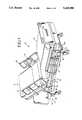
- FIG. 1is an elevational view showing a representative hospital bed which includes the weighing assembly of the present invention.
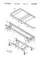
- FIG. 2is an exploded view of a portion of the bed of FIG. 1 including a lower bed frame with a load cell assembly, an upper bed frame and an articulated patient support frame.
- FIG. 3is a perspective view showing a portion of the bed weighing assembly of the present invention.
- FIG. 4is a cross-sectional view taken along lines 4--4 in FIG. 3.
- FIG. 5is a close-up view of a portion of FIG. 4.
- FIG. 6is an exploded view of the weighing assembly of the present invention.
- the improved weighing bed of the present inventionis shown generally at 10 in FIG. 1.
- the weighing bed 10portions of which are also shown in FIG. 2, includes an articulated patient support assembly 12, an upper bed frame 14 and a lower bed frame 16.
- a weighing assembly, shown generally at 18,is positioned in the embodiment shown between upper bed frame 14 and lower bed frame 16, and is mounted on the lower bed frame.
- the patient support assembly 12includes an articulated frame 20 (FIG. 2) and a flexible mattress 13, upon which the patient lies, as well as side panels 24 and 26, which include operational controls 28 for the bed 10.
- the articulated frame 20comprises four successive sections 27-30 of selected dimensions, as shown in FIG. 2. Each section is connected to the adjacent sections and can rotate relative thereto. This arrangement provides the overall range of motion and the positional capability necessary for a hospital bed.
- the operational controls 28connect with conventional motors (not shown) and associated mechanisms positioned beneath articulated frame 20 to provide the necessary powered movement for the bed.
- the upper bed frame 14provides direct support for the patient support assembly 12 and, in the embodiment shown, serves as a base or mounting structure for the motors and associated mechanisms, which move the patient support assembly into the desired positional configurations.
- the upper bed frame 14includes two elongated, generally straight longitudinal members 31-31, which extend for the length of the bed. While each longitudinal member 31 is shown as a single unit, they each could be two units telescopically joined together.
- the two longitudinal members 31-31are joined together by two lateral brace assemblies 32 and 34.
- the brace assemblies 32, 34generally each include bracket-like members 36-36, which depend from the head and foot ends of both of the longitudinal members, with a generally tubular support element 37 which extends between each set of brackets 36-36.
- the lower bed frame 16includes two elongated longitudinal members 42 and 44.
- the longitudinal membersflare outwardly in the vicinity of each end, terminating in caster assemblies 45-45.
- the caster assembliespermit the bed to be conveniently moved from place to place.
- Extending between the two longitudinal members 42 and 44 of the lower bed frameare two lateral braces 48 and 50.
- the lateral bracesare positioned approximately at the point along the length of each longitudinal member where the longitudinal member begins to flare outwardly.
- the patient support assembly 12, the upper bed frame 14 and the lower bed frame 16are generally conventional in design and construction. Typically, those portions are made from steel, with the component portions thereof being welded together. Such an arrangement provides the required stability and strength needed for a hospital bed.
- the controls and motors, gears and hydraulic actuators to control the movement and the required bed positionare also generally conventional.
- the actual configuration of the various portions of the bed described abovemay, however, vary within the spirit of the present invention.
- the weighing system or assembly of the present inventionincludes two load cells 52, 53, each load cell being approximately 24 inches long by 11/2 inches high by 3/4 inches wide, and made from aluminum.
- the load cellsare secured to the lower bed frame, in particular, to the respective longitudinal members 42 and 44 of the lower bed frame, through an elongated mounting plate 57. Screws 60-60 extend through three spaced openings 54, 56, and 58 in the load cell and into mounting plate 57, which is secured to the lower bed frame, such as by welding or the like.
- the lower surface 61 of the load cell in the vicinity of each end 67a, 67b thereofis slightly relieved over a length of approximately 4 inches, leaving a gap 71 (FIG. 5) between the lower surface of the relieved portions of the load cell and the mounting plate 57 of approximately 50-100 thousandths of an inch.
- Each cutout portion(i.e. cutout portion 64 in FIG. 5) includes 3/4 circle portions 64a, 64b connected by two flat portions 64c, 64d.
- strain gagesPositioned in the cutout portions and more particularly on the circle portions thereof are conventional strain gages, such as shown at 66 in FIG. 5.
- the strain gagesare connected electrically into a conventional Wheatstone bridge arrangement, with temperature compensating elements, shown representationally at 68, the output of which is connected via a cable 69 to a processing circuit and weight indicator 70.
- Load cell brackets 72-72are bolted to the top of each load cell 52, 53 in the vicinity of the opposite ends thereof, outboard of the cutout portions 62-65, which in turn are generally outboard of the nearest opening in the load cell by which the load cell is bolted to the mounting plate 57.
- FIG. 5shows the connection of the bracket 72 to the load cell 52.
- the bracket 72includes a opening 59 through which a screw extends into a threaded opening 55 in the load cell 52.
- the area immediately surrounding opening 59is dimpled inwardly and it is this area only which contacts the upper surface of the load cell 52.
- a set screw 69is positioned in the threaded opening 59 at a desired height for precision overload adjustment.
- load cell bracket 72 in the embodiment showncovers load cell 52 and extends beyond the respective ends of the load cell.
- the structure described below with respect to the bracket 72 used with load cell 52is the same for the bracket used with load cell 53 on the other side of the bed.
- load cell bracket 72includes three portions, an elongated main section 74, an ear portion 76 extending from one end 73 thereof, and an angled portion 78 extending from the other end 75 thereof.
- the main section 74is U-shaped in cross section, approximately 11/2 inches wide by 2 inches deep.
- the load cell bracket 72is made from 3/16 inch steel so that it is quite rigid and strong, for reasons clarified below.
- the main portion 74 of the bracketis approximately 32 inches long, such that it extends several inches beyond each end of the load cell when it is in place, bolted to the load cell.
- the ear portion 76is a 3/16 inch steel plate which extends approximately 2 inches from the one end 73 of the main portion 74, and is typically attached to the main portion 74 by welding.
- the ear portion in the embodiment shownis approximately 2 inches wide by 3 inches high, with the top edge being curved and extending at its highest point approximately 11/8 inches above the upper surface 82 of main portion 74.
- the ear portion 76has an opening 80 therethrough, approximately 1/2 inch in diameter and approximately at the level of the upper surface 82 of the main portion 74.
- Opening 80accommodates the rotatable attachment of a first link member 84, which extends from ear portion 76 of bracket 72 to the upper bed frame 14.
- first link member 84is approximately 12 inches long by 11/2 inches wide and is made from 3/16 inch steel stock.
- One end 86 of link 84is secured by means of a pin, bolt or the like to the ear portion 76 of the load cell bracket 72, so that link 84 is rotatable relative thereto.
- the other end of link 84is in the embodiment shown rotatably attached to the foot end lateral brace assembly 34 (in particular, at the end of tubular support 37) of the upper bed frame 14.
- a stop element 85(FIG. 4) is positioned on link 84 such that it abuts against ear 76 in the extreme position of link 84.
- Very large forcesare focused at the end of bracket 72 adjacent link 84 during movement of the bed, particularly in the Trendellenberg positions. These forces would ordinarily be sufficient to damage the end of a load cell.
- the strong bracket arrangement, and the manner of attaching the bracket to the load cell at the opposing ends thereofresults in the bracket being able to absorb the high forces without the load cell being damaged, while at the same time permitting the load cell to absorb the vertical load of the patient and be sensitive enough to give an accurate weight measurement.
- the angled portion 78 of bracket 72which extends from end 75 thereof, comprises two elongated plates 87 and 89, which in the embodiment shown are extensions of the respective wall portions of the U-shaped main portion 74 of the bracket.
- the plates 87 and 89are approximately 61/2 inches long by 13/4 inches wide and extend at an angle of approximately 30° downwardly from the end 75 of main portion 74.
- Near the free ends 91 of plates 87, 89are openings 88.
- a mounting bolt 95(FIG. 6) fits through the openings 88 in the plates 87 and 89 and into the lower bed frame.
- One end 97 of a second link member 90is rotatably positioned on the bolt 95, between the two plates 87, 89. Second link 90 extends upwardly from the mounting bolt and is approximately 12 inches long by 11/2 inches wide.
- One end of a third link member 92(FIG. 2) is rotatably attached to the other end of the second link member 90.
- the third link 92 in the embodiment shownis approximately 10 inches long by 11/2 inches wide.
- the other end of third link 92is rotatably attached to the head end lateral brace assembly 32 (the end of tubular support 37 thereof) of upper bed frame 14, as shown in FIG. 2.
- load cell bracket 72will remain in fixed position relative to the lower bed frame 16 and all other parts of the system.
- the first and second link members 84, 90will rotate about their respective points of connection, which are fixed, on the ear portion 76 and the angled portion 78, respectively, of the bracket 72.
- the first link member 84also rotates about its point of connection with the upper bed frame at foot end tubular support 37.
- the second link member 90also rotates about its point of connection with the third link member 92, while the third link member rotates about its connection with the upper bed frame at head end tubular support 37.
- the entire upper bed frame 14moves as the bed position changes.
- the load cellsare mounted to the lower bed frame and are hence directly responsive to the vertical loads produced by the patient in the bed.
- the load cellsare sufficiently sensitive to produce accurate weighing results within a fraction of a pound.
- the bracket 72takes up the large horizontal and twisting forces generated by the linkages as the bed moves into various positions, thereby protecting the load cell from damage.
Landscapes
- Physics & Mathematics (AREA)
- General Physics & Mathematics (AREA)
- Invalid Beds And Related Equipment (AREA)
Abstract
Description
Claims (13)
Priority Applications (2)
| Application Number | Priority Date | Filing Date | Title |
|---|---|---|---|
| US07/791,565US5269388A (en) | 1991-11-12 | 1991-11-12 | Weighing bed |
| PCT/US1992/009665WO1993010423A1 (en) | 1991-11-12 | 1992-11-12 | Weighing bed |
Applications Claiming Priority (1)
| Application Number | Priority Date | Filing Date | Title |
|---|---|---|---|
| US07/791,565US5269388A (en) | 1991-11-12 | 1991-11-12 | Weighing bed |
Publications (1)
| Publication Number | Publication Date |
|---|---|
| US5269388Atrue US5269388A (en) | 1993-12-14 |
Family
ID=25154111
Family Applications (1)
| Application Number | Title | Priority Date | Filing Date |
|---|---|---|---|
| US07/791,565Expired - LifetimeUS5269388A (en) | 1991-11-12 | 1991-11-12 | Weighing bed |
Country Status (2)
| Country | Link |
|---|---|
| US (1) | US5269388A (en) |
| WO (1) | WO1993010423A1 (en) |
Cited By (66)
| Publication number | Priority date | Publication date | Assignee | Title |
|---|---|---|---|---|
| US5393938A (en)* | 1993-05-06 | 1995-02-28 | Bio Clinic Corporation | In-bed patient scale |
| US5732423A (en)* | 1995-08-04 | 1998-03-31 | Hill-Rom, Inc. | Bed side rails |
| US5823278A (en)* | 1994-10-13 | 1998-10-20 | Future Systems, Inc. | Caster mounted weighing system |
| US5831221A (en)* | 1994-10-13 | 1998-11-03 | Future Sysems, Inc. | Caster mounted weighing system |
| US5859390A (en)* | 1996-10-23 | 1999-01-12 | Hill-Rom, Inc. | Hospital bed scale mounting apparatus |
| US5906016A (en)* | 1988-03-23 | 1999-05-25 | Hill-Rom | Patient care system |
| US6208250B1 (en) | 1999-03-05 | 2001-03-27 | Hill-Rom, Inc. | Patient position detection apparatus for a bed |
| USD458481S1 (en) | 2001-04-05 | 2002-06-11 | Hill-Rom Services, Inc. | Slats of a bed siderail |
| USD459119S1 (en) | 2001-04-05 | 2002-06-25 | Hill-Rom Services, Inc. | Siderail support arm |
| USD463179S1 (en) | 2001-04-05 | 2002-09-24 | Hill-Rom Services, Inc. | Top rail member of a bed siderail |
| US20030140714A1 (en)* | 2002-01-31 | 2003-07-31 | Debojit Barua | Integrated loadcell system |
| USD479070S1 (en) | 2002-09-06 | 2003-09-02 | Hill-Rom Services, Inc. | Bed siderail |
| US20030167568A1 (en)* | 2001-12-20 | 2003-09-11 | Brooke Jason C. | Bed siderails |
| USD480887S1 (en) | 2001-03-12 | 2003-10-21 | Xdin Ab (Publ) | Bed |
| US6680443B2 (en) | 2001-06-22 | 2004-01-20 | Hill-Rom Services, Inc. | Load cell apparatus having a gap measuring device |
| US6694549B2 (en) | 2001-04-20 | 2004-02-24 | Hill-Rom Services, Inc. | Bed frame with reduced-shear pivot |
| US6765154B2 (en) | 2001-12-18 | 2004-07-20 | Louis E. Sternberg | Portable, adjustable bed weighing system |
| US6791460B2 (en) | 1999-03-05 | 2004-09-14 | Hill-Rom Services, Inc. | Patient position detection apparatus for a bed |
| US6829796B2 (en) | 2001-10-02 | 2004-12-14 | Hill-Rom Services, Inc. | Integrated barrier and fluid supply for a hospital bed |
| US6924441B1 (en) | 1999-09-29 | 2005-08-02 | Hill-Rom Services, Inc. | Load cell apparatus |
| US20060059814A1 (en)* | 2004-09-13 | 2006-03-23 | Metz Darrell L | Load cell to frame interface for hospital bed |
| US20060195986A1 (en)* | 2005-03-07 | 2006-09-07 | Reza Hakamiun | Footboard for a hospital bed |
| US7253366B2 (en) | 2004-08-09 | 2007-08-07 | Hill-Rom Services, Inc. | Exit alarm for a hospital bed triggered by individual load cell weight readings exceeding a predetermined threshold |
| US7296312B2 (en) | 2002-09-06 | 2007-11-20 | Hill-Rom Services, Inc. | Hospital bed |
| US20070296600A1 (en)* | 1999-03-05 | 2007-12-27 | Dixon Steven A | Obstruction detection apparatus for a bed |
| US20080263771A1 (en)* | 2007-04-27 | 2008-10-30 | Hill-Rom Services, Inc. | Endboard for a patient support |
| US7523515B2 (en) | 1995-01-03 | 2009-04-28 | Hill-Rom Services, Inc. | Hospital bed and mattress having a retractable foot section |
| US20110029169A1 (en)* | 2009-07-31 | 2011-02-03 | Control Solutions LLC | Controller and methods of controlling a personal electric motorized vehicle based on a weight of an operator |
| US20110113562A1 (en)* | 2009-11-16 | 2011-05-19 | Uzzle Thomas E | Endboard for person support apparatus |
| US8090478B2 (en) | 2005-06-10 | 2012-01-03 | Hill-Rom Services, Inc. | Control for pressurized bladder in a patient support apparatus |
| US8286282B2 (en) | 1995-08-04 | 2012-10-16 | Hill-Rom Services, Inc. | Bed frame and mattress synchronous control |
| US8344860B2 (en) | 2004-08-02 | 2013-01-01 | Hill-Rom Services, Inc. | Patient support apparatus alert system |
| US8432287B2 (en) | 2010-07-30 | 2013-04-30 | Hill-Rom Services, Inc. | Apparatus for controlling room lighting in response to bed exit |
| US20130146371A1 (en)* | 2011-12-08 | 2013-06-13 | Caremed Supply Inc. | Real-time weighing device for use with hospital bed |
| US8464380B2 (en) | 2005-07-08 | 2013-06-18 | Hill-Rom Services, Inc. | Patient support apparatus having alert light |
| US8537008B2 (en) | 2008-09-19 | 2013-09-17 | Hill-Rom Services, Inc. | Bed status indicators |
| US20140069729A1 (en)* | 2012-09-10 | 2014-03-13 | Caremed Supply Inc. | Real-time weight measuring system for hospital bed |
| US8717181B2 (en) | 2010-07-29 | 2014-05-06 | Hill-Rom Services, Inc. | Bed exit alert silence with automatic re-enable |
| USD710507S1 (en) | 2013-09-23 | 2014-08-05 | Hill-Rom Services Pte. Ltd. | Patient bed |
| USD710509S1 (en) | 2013-09-23 | 2014-08-05 | Hill-Rom Services Pte. Ltd. | Head rail for a patient bed |
| USD710510S1 (en) | 2013-09-23 | 2014-08-05 | Hill-Rom Services Pte. Ltd. | Foot rail for a patient bed |
| US9009893B2 (en) | 1999-12-29 | 2015-04-21 | Hill-Rom Services, Inc. | Hospital bed |
| US9089459B2 (en) | 2013-11-18 | 2015-07-28 | Völker GmbH | Person support apparatus |
| US9400207B2 (en) | 2013-03-15 | 2016-07-26 | Illinois Tool Works Inc. | Sensor mounting bracket |
| USD768422S1 (en) | 2014-08-12 | 2016-10-11 | Hill-Rom Services, Inc. | Foot end siderail |
| USD769042S1 (en) | 2014-08-12 | 2016-10-18 | Hill-Rom Services, Inc. | Head end siderail |
| USD770829S1 (en) | 2015-01-29 | 2016-11-08 | Hill-Rom Services, Inc. | Head rail for patient bed |
| USD770824S1 (en) | 2014-08-12 | 2016-11-08 | Hill-Rom Services, Inc. | Barrier for a hospital bed |
| USD771259S1 (en) | 2015-01-29 | 2016-11-08 | Hill-Rom Services, Inc. | Foot rail for patient bed |
| USD779074S1 (en)* | 2015-07-29 | 2017-02-14 | Midmark Corporation | Armrest for medical examination table |
| US9655798B2 (en) | 2013-03-14 | 2017-05-23 | Hill-Rom Services, Inc. | Multi-alert lights for hospital bed |
| USD804883S1 (en) | 2016-05-28 | 2017-12-12 | Hill-Rom Services, Inc. | Footrail |
| USD804882S1 (en) | 2016-05-28 | 2017-12-12 | Hill-Rom Services, Inc. | Headrail |
| US9875633B2 (en) | 2014-09-11 | 2018-01-23 | Hill-Rom Sas | Patient support apparatus |
| US20190033122A1 (en)* | 2014-05-09 | 2019-01-31 | Daniel Lin | Method and System to Track Weight Without Stepping on a Weight Scale |
| US10206836B2 (en) | 2011-11-11 | 2019-02-19 | Hill-Rom Services, Inc. | Bed exit alerts for person support apparatus |
| US10292605B2 (en) | 2012-11-15 | 2019-05-21 | Hill-Rom Services, Inc. | Bed load cell based physiological sensing systems and methods |
| US10959534B2 (en) | 2019-02-28 | 2021-03-30 | Hill-Rom Services, Inc. | Oblique hinged panels and bladder apparatus for sleep disorders |
| WO2021108377A1 (en) | 2019-11-27 | 2021-06-03 | Stryker Corporation | Patient support apparatus with load cell assemblies |
| US11229568B2 (en) | 2018-09-30 | 2022-01-25 | Hill-Rom Services, Inc. | Mattress support for adding hospital bed functionality to an in-home bed |
| US11241347B2 (en) | 2018-10-01 | 2022-02-08 | Hill-Rom Services, Inc. | Mattress support for adding hospital bed modular control system for upgrading a bed to include movable components |
| US11243110B2 (en)* | 2014-05-09 | 2022-02-08 | Daniel Lin | Method and system to track weight without stepping on a weight scale |
| US11357682B2 (en) | 2018-09-30 | 2022-06-14 | Hill-Rom Services, Inc. | Structures for causing movement of elements of a bed |
| US11367535B2 (en) | 2018-09-30 | 2022-06-21 | Hill-Rom Services, Inc. | Patient care system for a home environment |
| US11400001B2 (en) | 2018-10-01 | 2022-08-02 | Hill-Rom Services, Inc. | Method and apparatus for upgrading a bed to include moveable components |
| EP4175602B1 (en) | 2020-07-06 | 2024-10-02 | Arjo IP Holding Aktiebolag | Patient handling apparatus |
Families Citing this family (4)
| Publication number | Priority date | Publication date | Assignee | Title |
|---|---|---|---|---|
| FR2711520A1 (en)* | 1993-10-19 | 1995-05-05 | Brenot Claude | Modular invalid bed with integrated weighing system |
| CN104177497B (en) | 2005-02-08 | 2018-01-16 | 根茨美公司 | For TGF β antibody |
| TWI529247B (en) | 2009-05-13 | 2016-04-11 | 建新公司 | Anti-human cd52 immunoglobulins |
| AR095199A1 (en) | 2013-03-15 | 2015-09-30 | Genzyme Corp | ANTI-CD52 ANTIBODIES |
Citations (2)
| Publication number | Priority date | Publication date | Assignee | Title |
|---|---|---|---|---|
| US4926951A (en)* | 1989-06-26 | 1990-05-22 | Ssi Medical Services, Inc. | Weigh bed |
| US4934468A (en)* | 1987-12-28 | 1990-06-19 | Hill-Rom Company, Inc. | Hospital bed for weighing patients |
- 1991
- 1991-11-12USUS07/791,565patent/US5269388A/ennot_activeExpired - Lifetime
- 1992
- 1992-11-12WOPCT/US1992/009665patent/WO1993010423A1/enactiveApplication Filing
Patent Citations (2)
| Publication number | Priority date | Publication date | Assignee | Title |
|---|---|---|---|---|
| US4934468A (en)* | 1987-12-28 | 1990-06-19 | Hill-Rom Company, Inc. | Hospital bed for weighing patients |
| US4926951A (en)* | 1989-06-26 | 1990-05-22 | Ssi Medical Services, Inc. | Weigh bed |
Cited By (123)
| Publication number | Priority date | Publication date | Assignee | Title |
|---|---|---|---|---|
| US6668408B2 (en) | 1988-03-23 | 2003-12-30 | Hill-Rom Services, Inc. | Patient care system |
| US5906016A (en)* | 1988-03-23 | 1999-05-25 | Hill-Rom | Patient care system |
| US6941598B2 (en) | 1988-03-23 | 2005-09-13 | Hill-Rom Services, Inc. | Patient care system |
| US6438776B2 (en)* | 1992-04-03 | 2002-08-27 | Hill-Rom Services, Inc. | Patient care system |
| US5393938A (en)* | 1993-05-06 | 1995-02-28 | Bio Clinic Corporation | In-bed patient scale |
| US5823278A (en)* | 1994-10-13 | 1998-10-20 | Future Systems, Inc. | Caster mounted weighing system |
| US5831221A (en)* | 1994-10-13 | 1998-11-03 | Future Sysems, Inc. | Caster mounted weighing system |
| US7523515B2 (en) | 1995-01-03 | 2009-04-28 | Hill-Rom Services, Inc. | Hospital bed and mattress having a retractable foot section |
| US5732423A (en)* | 1995-08-04 | 1998-03-31 | Hill-Rom, Inc. | Bed side rails |
| US6182310B1 (en) | 1995-08-04 | 2001-02-06 | Hill-Rom, Inc. | Bed side rails |
| US8286282B2 (en) | 1995-08-04 | 2012-10-16 | Hill-Rom Services, Inc. | Bed frame and mattress synchronous control |
| US5859390A (en)* | 1996-10-23 | 1999-01-12 | Hill-Rom, Inc. | Hospital bed scale mounting apparatus |
| US8258963B2 (en) | 1999-03-05 | 2012-09-04 | Hill-Rom Services, Inc. | Body position monitoring system |
| US20050035871A1 (en)* | 1999-03-05 | 2005-02-17 | Hill-Rom Services, Inc. | Patient position detection apparatus for a bed |
| US20080010747A1 (en)* | 1999-03-05 | 2008-01-17 | Dixon Stephen A | Electrical Connector Assembly Suitable for a Bed Footboard |
| US6208250B1 (en) | 1999-03-05 | 2001-03-27 | Hill-Rom, Inc. | Patient position detection apparatus for a bed |
| US7834768B2 (en) | 1999-03-05 | 2010-11-16 | Hill-Rom Services, Inc. | Obstruction detection apparatus for a bed |
| US7978084B2 (en) | 1999-03-05 | 2011-07-12 | Hill-Rom Services, Inc. | Body position monitoring system |
| US8525682B2 (en) | 1999-03-05 | 2013-09-03 | Hill-Rom Services, Inc. | Hospital bed having alert light |
| US6320510B2 (en) | 1999-03-05 | 2001-11-20 | Douglas J. Menkedick | Bed control apparatus |
| US8400311B2 (en) | 1999-03-05 | 2013-03-19 | Hill-Rom Services, Inc. | Hospital bed having alert light |
| US6791460B2 (en) | 1999-03-05 | 2004-09-14 | Hill-Rom Services, Inc. | Patient position detection apparatus for a bed |
| US20050166324A1 (en)* | 1999-03-05 | 2005-08-04 | Dixon Stephen A. | Romovable footboard for a hospital bed |
| US8830070B2 (en) | 1999-03-05 | 2014-09-09 | Hill-Rom Services, Inc. | Hospital bed having alert light |
| US20070296600A1 (en)* | 1999-03-05 | 2007-12-27 | Dixon Steven A | Obstruction detection apparatus for a bed |
| US7986242B2 (en) | 1999-03-05 | 2011-07-26 | Hill-Rom Services, Inc. | Electrical connector assembly suitable for a bed footboard |
| US6924441B1 (en) | 1999-09-29 | 2005-08-02 | Hill-Rom Services, Inc. | Load cell apparatus |
| US10251797B2 (en) | 1999-12-29 | 2019-04-09 | Hill-Rom Services, Inc. | Hospital bed |
| US9009893B2 (en) | 1999-12-29 | 2015-04-21 | Hill-Rom Services, Inc. | Hospital bed |
| USD480887S1 (en) | 2001-03-12 | 2003-10-21 | Xdin Ab (Publ) | Bed |
| USD458481S1 (en) | 2001-04-05 | 2002-06-11 | Hill-Rom Services, Inc. | Slats of a bed siderail |
| USD459119S1 (en) | 2001-04-05 | 2002-06-25 | Hill-Rom Services, Inc. | Siderail support arm |
| USD463179S1 (en) | 2001-04-05 | 2002-09-24 | Hill-Rom Services, Inc. | Top rail member of a bed siderail |
| US6694549B2 (en) | 2001-04-20 | 2004-02-24 | Hill-Rom Services, Inc. | Bed frame with reduced-shear pivot |
| US6680443B2 (en) | 2001-06-22 | 2004-01-20 | Hill-Rom Services, Inc. | Load cell apparatus having a gap measuring device |
| US7310839B2 (en) | 2001-10-02 | 2007-12-25 | Hill-Rom Services, Inc. | Patient support apparatus |
| US6829796B2 (en) | 2001-10-02 | 2004-12-14 | Hill-Rom Services, Inc. | Integrated barrier and fluid supply for a hospital bed |
| US20050091753A1 (en)* | 2001-10-02 | 2005-05-05 | Hill-Rom Services, Inc. | Patient support apparatus |
| US6765154B2 (en) | 2001-12-18 | 2004-07-20 | Louis E. Sternberg | Portable, adjustable bed weighing system |
| US20030167568A1 (en)* | 2001-12-20 | 2003-09-11 | Brooke Jason C. | Bed siderails |
| US6898988B2 (en)* | 2002-01-31 | 2005-05-31 | Autoliv Asp, Inc. | Integrated load cell system |
| US20030140714A1 (en)* | 2002-01-31 | 2003-07-31 | Debojit Barua | Integrated loadcell system |
| US7506390B2 (en) | 2002-09-06 | 2009-03-24 | Hill-Rom Services, Inc. | Patient support apparatus having controller area network |
| US7520006B2 (en) | 2002-09-06 | 2009-04-21 | Hill-Rom Services, Inc. | Hospital bed including moveable foot portion |
| US7296312B2 (en) | 2002-09-06 | 2007-11-20 | Hill-Rom Services, Inc. | Hospital bed |
| US7669263B2 (en) | 2002-09-06 | 2010-03-02 | Hill-Rom Services, Inc. | Mattress assembly including adjustable length foot |
| US7703158B2 (en) | 2002-09-06 | 2010-04-27 | Hill-Rom Services, Inc. | Patient support apparatus having a diagnostic system |
| USD479070S1 (en) | 2002-09-06 | 2003-09-02 | Hill-Rom Services, Inc. | Bed siderail |
| US7406731B2 (en) | 2002-09-06 | 2008-08-05 | Holl-Rom Services, Inc. | Hospital bed |
| USRE43532E1 (en) | 2002-09-06 | 2012-07-24 | Hill-Rom Services, Inc. | Hospital bed |
| US8344860B2 (en) | 2004-08-02 | 2013-01-01 | Hill-Rom Services, Inc. | Patient support apparatus alert system |
| US7437787B2 (en) | 2004-08-09 | 2008-10-21 | Hill-Rom Services, Inc. | Load-cell based hospital bed control |
| US7253366B2 (en) | 2004-08-09 | 2007-08-07 | Hill-Rom Services, Inc. | Exit alarm for a hospital bed triggered by individual load cell weight readings exceeding a predetermined threshold |
| US20060059814A1 (en)* | 2004-09-13 | 2006-03-23 | Metz Darrell L | Load cell to frame interface for hospital bed |
| US7176391B2 (en) | 2004-09-13 | 2007-02-13 | Hill-Rom Services, Inc. | Load cell to frame interface for hospital bed |
| US7335839B2 (en) | 2004-09-13 | 2008-02-26 | Hill-Rom Services, Inc. | Load cell interface for a bed having a stud receiver with a roller axis parallel with an axis of a load cell stud |
| US20070107948A1 (en)* | 2004-09-13 | 2007-05-17 | Metz Darrell L | Load cell to frame interface for hospital bed |
| US20060195986A1 (en)* | 2005-03-07 | 2006-09-07 | Reza Hakamiun | Footboard for a hospital bed |
| US8090478B2 (en) | 2005-06-10 | 2012-01-03 | Hill-Rom Services, Inc. | Control for pressurized bladder in a patient support apparatus |
| US8620477B2 (en) | 2005-06-10 | 2013-12-31 | Hill-Rom Services, Inc. | Control for pressurized bladder in a patient support apparatus |
| US9107511B2 (en) | 2005-06-10 | 2015-08-18 | Hill-Rom Services, Inc. | Control for pressurized bladder in a patient support apparatus |
| US10561550B2 (en) | 2005-07-08 | 2020-02-18 | Hill-Rom Services, Inc. | Patient support apparatus having alert light |
| US8464380B2 (en) | 2005-07-08 | 2013-06-18 | Hill-Rom Services, Inc. | Patient support apparatus having alert light |
| US9220650B2 (en) | 2005-07-08 | 2015-12-29 | Hill-Rom Services, Inc. | Patient support apparatus having alert light |
| US7904976B2 (en) | 2007-04-27 | 2011-03-15 | Hill-Rom Services, Inc. | Endboard for a patient support |
| US20110162142A1 (en)* | 2007-04-27 | 2011-07-07 | Reza Hakamiun | Endboard for a patient support |
| US20080263771A1 (en)* | 2007-04-27 | 2008-10-30 | Hill-Rom Services, Inc. | Endboard for a patient support |
| US8593284B2 (en) | 2008-09-19 | 2013-11-26 | Hill-Rom Services, Inc. | System and method for reporting status of a bed |
| US8537008B2 (en) | 2008-09-19 | 2013-09-17 | Hill-Rom Services, Inc. | Bed status indicators |
| US8847756B2 (en) | 2008-09-19 | 2014-09-30 | Hill-Rom Services, Inc. | Bed status indicators |
| US8594868B2 (en) | 2009-07-31 | 2013-11-26 | Control Solutions LLC | Controller and methods of controlling a personal electric motorized vehicle based on a weight of an operator |
| US20110029169A1 (en)* | 2009-07-31 | 2011-02-03 | Control Solutions LLC | Controller and methods of controlling a personal electric motorized vehicle based on a weight of an operator |
| US20110113562A1 (en)* | 2009-11-16 | 2011-05-19 | Uzzle Thomas E | Endboard for person support apparatus |
| US8717181B2 (en) | 2010-07-29 | 2014-05-06 | Hill-Rom Services, Inc. | Bed exit alert silence with automatic re-enable |
| US8432287B2 (en) | 2010-07-30 | 2013-04-30 | Hill-Rom Services, Inc. | Apparatus for controlling room lighting in response to bed exit |
| US10206836B2 (en) | 2011-11-11 | 2019-02-19 | Hill-Rom Services, Inc. | Bed exit alerts for person support apparatus |
| US20130146371A1 (en)* | 2011-12-08 | 2013-06-13 | Caremed Supply Inc. | Real-time weighing device for use with hospital bed |
| US20140069729A1 (en)* | 2012-09-10 | 2014-03-13 | Caremed Supply Inc. | Real-time weight measuring system for hospital bed |
| US10292605B2 (en) | 2012-11-15 | 2019-05-21 | Hill-Rom Services, Inc. | Bed load cell based physiological sensing systems and methods |
| US11464692B2 (en) | 2013-03-14 | 2022-10-11 | Hill-Rom Services, Inc. | Multi-alert lights for hospital bed |
| US10413465B2 (en) | 2013-03-14 | 2019-09-17 | Hill-Rom Services, Inc. | Multi-alert lights for hospital bed |
| US10709625B2 (en) | 2013-03-14 | 2020-07-14 | Hill-Rom Services, Inc. | Foot end alert display for hospital bed |
| US10918546B2 (en) | 2013-03-14 | 2021-02-16 | Hill-Rom Services, Inc. | Multi-alert lights for hospital bed |
| US11833090B2 (en) | 2013-03-14 | 2023-12-05 | Hill-Rom Services, Inc. | Multi-alert lights for hospital bed |
| US10512574B2 (en) | 2013-03-14 | 2019-12-24 | Hill-Rom Services, Inc. | Multi-alert lights for hospital bed |
| US12186249B2 (en) | 2013-03-14 | 2025-01-07 | Hill-Rom Services, Inc. | Multi-alert lights for hospital bed |
| US9655798B2 (en) | 2013-03-14 | 2017-05-23 | Hill-Rom Services, Inc. | Multi-alert lights for hospital bed |
| US9400207B2 (en) | 2013-03-15 | 2016-07-26 | Illinois Tool Works Inc. | Sensor mounting bracket |
| USD710507S1 (en) | 2013-09-23 | 2014-08-05 | Hill-Rom Services Pte. Ltd. | Patient bed |
| USD710510S1 (en) | 2013-09-23 | 2014-08-05 | Hill-Rom Services Pte. Ltd. | Foot rail for a patient bed |
| USD710509S1 (en) | 2013-09-23 | 2014-08-05 | Hill-Rom Services Pte. Ltd. | Head rail for a patient bed |
| US9089459B2 (en) | 2013-11-18 | 2015-07-28 | Völker GmbH | Person support apparatus |
| US10466094B2 (en)* | 2014-05-09 | 2019-11-05 | Daniel Lin | Method and system to track weight without stepping on a weight scale |
| US11243110B2 (en)* | 2014-05-09 | 2022-02-08 | Daniel Lin | Method and system to track weight without stepping on a weight scale |
| US20190033122A1 (en)* | 2014-05-09 | 2019-01-31 | Daniel Lin | Method and System to Track Weight Without Stepping on a Weight Scale |
| USD770824S1 (en) | 2014-08-12 | 2016-11-08 | Hill-Rom Services, Inc. | Barrier for a hospital bed |
| USD825973S1 (en) | 2014-08-12 | 2018-08-21 | Hill-Rom Services, Inc. | Barrier for a hospital bed |
| USD819382S1 (en) | 2014-08-12 | 2018-06-05 | Hill-Rom Services, Inc. | Head end siderail |
| USD817682S1 (en) | 2014-08-12 | 2018-05-15 | Hill-Rom Services, Inc. | Foot end siderail |
| USD769042S1 (en) | 2014-08-12 | 2016-10-18 | Hill-Rom Services, Inc. | Head end siderail |
| USD768422S1 (en) | 2014-08-12 | 2016-10-11 | Hill-Rom Services, Inc. | Foot end siderail |
| US10276021B2 (en) | 2014-09-11 | 2019-04-30 | Hill-Rom Sas | Patient support apparatus having articulated mattress support deck with load sensors |
| US9875633B2 (en) | 2014-09-11 | 2018-01-23 | Hill-Rom Sas | Patient support apparatus |
| USD855369S1 (en) | 2015-01-29 | 2019-08-06 | Hill-Rom Services, Inc. | Foot rail for patient bed |
| USD817058S1 (en) | 2015-01-29 | 2018-05-08 | Hill-Rom Services, Inc. | Head rail for patient bed |
| USD771259S1 (en) | 2015-01-29 | 2016-11-08 | Hill-Rom Services, Inc. | Foot rail for patient bed |
| USD770829S1 (en) | 2015-01-29 | 2016-11-08 | Hill-Rom Services, Inc. | Head rail for patient bed |
| USD779074S1 (en)* | 2015-07-29 | 2017-02-14 | Midmark Corporation | Armrest for medical examination table |
| USD850836S1 (en) | 2016-05-28 | 2019-06-11 | Hill-Rom Services, Inc. | Footrail |
| USD858166S1 (en) | 2016-05-28 | 2019-09-03 | Hill-Rom Services, Inc. | Headrail |
| USD804883S1 (en) | 2016-05-28 | 2017-12-12 | Hill-Rom Services, Inc. | Footrail |
| USD804882S1 (en) | 2016-05-28 | 2017-12-12 | Hill-Rom Services, Inc. | Headrail |
| US11229568B2 (en) | 2018-09-30 | 2022-01-25 | Hill-Rom Services, Inc. | Mattress support for adding hospital bed functionality to an in-home bed |
| US11357682B2 (en) | 2018-09-30 | 2022-06-14 | Hill-Rom Services, Inc. | Structures for causing movement of elements of a bed |
| US11367535B2 (en) | 2018-09-30 | 2022-06-21 | Hill-Rom Services, Inc. | Patient care system for a home environment |
| US11400001B2 (en) | 2018-10-01 | 2022-08-02 | Hill-Rom Services, Inc. | Method and apparatus for upgrading a bed to include moveable components |
| US11241347B2 (en) | 2018-10-01 | 2022-02-08 | Hill-Rom Services, Inc. | Mattress support for adding hospital bed modular control system for upgrading a bed to include movable components |
| US11470978B2 (en) | 2019-02-28 | 2022-10-18 | Hill-Rom Services, Inc. | Oblique hinged panels and bladder apparatus for sleep disorders |
| US10959534B2 (en) | 2019-02-28 | 2021-03-30 | Hill-Rom Services, Inc. | Oblique hinged panels and bladder apparatus for sleep disorders |
| WO2021108377A1 (en) | 2019-11-27 | 2021-06-03 | Stryker Corporation | Patient support apparatus with load cell assemblies |
| EP4065061A4 (en)* | 2019-11-27 | 2023-12-27 | Stryker Corporation | PATIENT SUPPORT DEVICE WITH QUARTZ CELL ASSEMBLIES |
| US12251345B2 (en) | 2019-11-27 | 2025-03-18 | Stryker Corporation | Patient support apparatus with load cell assemblies |
| EP4175602B1 (en) | 2020-07-06 | 2024-10-02 | Arjo IP Holding Aktiebolag | Patient handling apparatus |
Also Published As
| Publication number | Publication date |
|---|---|
| WO1993010423A1 (en) | 1993-05-27 |
Similar Documents
| Publication | Publication Date | Title |
|---|---|---|
| US5269388A (en) | Weighing bed | |
| US4974692A (en) | Weigh bed | |
| EP1101481B1 (en) | Patient care system | |
| US4961470A (en) | Weigh bed having vertical load link | |
| US4926951A (en) | Weigh bed | |
| US4793428A (en) | Hospital bed with an integrated scale | |
| US4482783A (en) | Patient weighing scale with hoist | |
| US6439341B1 (en) | Apparatus for monitoring loading of a lift | |
| US7176391B2 (en) | Load cell to frame interface for hospital bed | |
| US6680443B2 (en) | Load cell apparatus having a gap measuring device | |
| US4831738A (en) | Capacitive extensometer | |
| JPS61270622A (en) | Mass and force measuring device | |
| CA1159853A (en) | Overhead track scale | |
| US4600067A (en) | Weighing apparatus with additional assembly for torsion compensation | |
| JPH0228029B2 (en) | ||
| JPS6116007B2 (en) | ||
| EP1216400A1 (en) | Load cell apparatus | |
| JPS6136939B2 (en) | ||
| JPS63201535A (en) | Stretcher with load cell | |
| US12378980B2 (en) | Rotary actuator unit with load control | |
| EP1695048B1 (en) | Load cell | |
| CA2040658A1 (en) | Load sensing assembly | |
| US20240398640A1 (en) | Fixing member, bed supporting structure, and bed | |
| US4561511A (en) | Torsion load cell | |
| JPH025381Y2 (en) |
Legal Events
| Date | Code | Title | Description |
|---|---|---|---|
| AS | Assignment | Owner name:STRESS-TEK, INC., WASHINGTON Free format text:ASSIGNMENT OF ASSIGNORS INTEREST.;ASSIGNORS:REICHOW, KEITH W.;HILDEBRANT, ROBERT L.;BUTLER, RICHARD A.;REEL/FRAME:005910/0848 Effective date:19911112 | |
| CC | Certificate of correction | ||
| FPAY | Fee payment | Year of fee payment:4 | |
| REMI | Maintenance fee reminder mailed | ||
| FEPP | Fee payment procedure | Free format text:PETITION RELATED TO MAINTENANCE FEES FILED (ORIGINAL EVENT CODE: PMFP); ENTITY STATUS OF PATENT OWNER: SMALL ENTITY | |
| FEPP | Fee payment procedure | Free format text:PETITION RELATED TO MAINTENANCE FEES GRANTED (ORIGINAL EVENT CODE: PMFG); ENTITY STATUS OF PATENT OWNER: SMALL ENTITY | |
| FPAY | Fee payment | Year of fee payment:8 | |
| FP | Lapsed due to failure to pay maintenance fee | Effective date:20011214 | |
| STCF | Information on status: patent grant | Free format text:PATENTED CASE | |
| SULP | Surcharge for late payment | ||
| PRDP | Patent reinstated due to the acceptance of a late maintenance fee | Effective date:20020311 | |
| REMI | Maintenance fee reminder mailed | ||
| FPAY | Fee payment | Year of fee payment:12 | |
| SULP | Surcharge for late payment | Year of fee payment:11 | |
| AS | Assignment | Owner name:JPMORGAN CHASE BANK, NATIONAL ASSOCIATION, AS AGEN Free format text:SECURITY INTEREST;ASSIGNOR:STRESS-TEK, INC.;REEL/FRAME:037481/0127 Effective date:20151230 |