US5269297A - Ultrasonic transmission apparatus - Google Patents
Ultrasonic transmission apparatusDownload PDFInfo
- Publication number
- US5269297A US5269297AUS07/842,529US84252992AUS5269297AUS 5269297 AUS5269297 AUS 5269297AUS 84252992 AUS84252992 AUS 84252992AUS 5269297 AUS5269297 AUS 5269297A
- Authority
- US
- United States
- Prior art keywords
- proximal
- horn
- transmitter
- tip
- distal
- Prior art date
- Legal status (The legal status is an assumption and is not a legal conclusion. Google has not performed a legal analysis and makes no representation as to the accuracy of the status listed.)
- Expired - Fee Related
Links
- 230000005540biological transmissionEffects0.000titleclaimsdescription73
- 238000006073displacement reactionMethods0.000claimsabstractdescription69
- 239000000463materialSubstances0.000claimsabstractdescription40
- 238000002604ultrasonographyMethods0.000claimsabstractdescription4
- 239000012530fluidSubstances0.000claimsdescription65
- 230000001681protective effectEffects0.000claimsdescription34
- 230000008878couplingEffects0.000claimsdescription31
- 238000010168coupling processMethods0.000claimsdescription31
- 238000005859coupling reactionMethods0.000claimsdescription31
- RTAQQCXQSZGOHL-UHFFFAOYSA-NTitaniumChemical compound[Ti]RTAQQCXQSZGOHL-UHFFFAOYSA-N0.000claimsdescription18
- 229910052719titaniumInorganic materials0.000claimsdescription15
- 239000010936titaniumSubstances0.000claimsdescription15
- 229910052782aluminiumInorganic materials0.000claimsdescription10
- XAGFODPZIPBFFR-UHFFFAOYSA-NaluminiumChemical compound[Al]XAGFODPZIPBFFR-UHFFFAOYSA-N0.000claimsdescription10
- 238000013016dampingMethods0.000claimsdescription8
- 238000004891communicationMethods0.000claimsdescription7
- 238000010276constructionMethods0.000claimsdescription6
- 230000002441reversible effectEffects0.000claimsdescription4
- 239000000314lubricantSubstances0.000claims2
- 210000004204blood vesselAnatomy0.000description33
- 208000007536ThrombosisDiseases0.000description26
- 238000002399angioplastyMethods0.000description23
- 206010017076FractureDiseases0.000description9
- 238000000034methodMethods0.000description9
- 230000002829reductive effectEffects0.000description9
- 208000010392Bone FracturesDiseases0.000description8
- 235000001674Agaricus brunnescensNutrition0.000description7
- 230000006378damageEffects0.000description7
- 206010016256fatigueDiseases0.000description7
- 238000013461designMethods0.000description6
- 125000006850spacer groupChemical group0.000description6
- 238000005452bendingMethods0.000description5
- 230000000694effectsEffects0.000description5
- FAPWRFPIFSIZLT-UHFFFAOYSA-MSodium chlorideChemical compound[Na+].[Cl-]FAPWRFPIFSIZLT-UHFFFAOYSA-M0.000description4
- 208000027418Wounds and injuryDiseases0.000description4
- 210000004369bloodAnatomy0.000description4
- 239000008280bloodSubstances0.000description4
- 208000014674injuryDiseases0.000description4
- 239000004033plasticSubstances0.000description4
- 229910000838Al alloyInorganic materials0.000description3
- 230000004044responseEffects0.000description3
- 239000011780sodium chlorideSubstances0.000description3
- 238000012360testing methodMethods0.000description3
- 230000002537thrombolytic effectEffects0.000description3
- 229910000737DuraluminInorganic materials0.000description2
- 229910001025HiduminiumInorganic materials0.000description2
- 239000000853adhesiveSubstances0.000description2
- 230000001070adhesive effectEffects0.000description2
- 230000008901benefitEffects0.000description2
- 238000001816coolingMethods0.000description2
- 210000003743erythrocyteAnatomy0.000description2
- 230000001747exhibiting effectEffects0.000description2
- 239000000835fiberSubstances0.000description2
- 230000020169heat generationEffects0.000description2
- 230000009467reductionEffects0.000description2
- 238000001356surgical procedureMethods0.000description2
- XLYOFNOQVPJJNP-UHFFFAOYSA-NwaterSubstancesOXLYOFNOQVPJJNP-UHFFFAOYSA-N0.000description2
- -1AL-7075Chemical compound0.000description1
- 241000283690Bos taurusSpecies0.000description1
- 206010011091Coronary artery thrombosisDiseases0.000description1
- 102000009123FibrinHuman genes0.000description1
- 108010073385FibrinProteins0.000description1
- BWGVNKXGVNDBDI-UHFFFAOYSA-NFibrin monomerChemical compoundCNC(=O)CNC(=O)CNBWGVNKXGVNDBDI-UHFFFAOYSA-N0.000description1
- 238000009825accumulationMethods0.000description1
- 230000002411adverseEffects0.000description1
- 229910045601alloyInorganic materials0.000description1
- 239000000956alloySubstances0.000description1
- 230000015572biosynthetic processEffects0.000description1
- 230000000295complement effectEffects0.000description1
- 208000002528coronary thrombosisDiseases0.000description1
- 210000004351coronary vesselAnatomy0.000description1
- 230000007423decreaseEffects0.000description1
- 230000003247decreasing effectEffects0.000description1
- 238000010586diagramMethods0.000description1
- 238000009826distributionMethods0.000description1
- 230000009977dual effectEffects0.000description1
- 230000002349favourable effectEffects0.000description1
- 210000001105femoral arteryAnatomy0.000description1
- 229950003499fibrinDrugs0.000description1
- 230000005484gravityEffects0.000description1
- 230000023597hemostasisEffects0.000description1
- 230000002439hemostatic effectEffects0.000description1
- 238000011835investigationMethods0.000description1
- 238000002955isolationMethods0.000description1
- 230000003902lesionEffects0.000description1
- 238000005461lubricationMethods0.000description1
- 230000007257malfunctionEffects0.000description1
- 238000004519manufacturing processMethods0.000description1
- 239000011159matrix materialSubstances0.000description1
- 239000000203mixtureSubstances0.000description1
- 230000036961partial effectEffects0.000description1
- 239000002245particleSubstances0.000description1
- 239000007787solidSubstances0.000description1
- 238000011144upstream manufacturingMethods0.000description1
- 230000002792vascularEffects0.000description1
- 238000003466weldingMethods0.000description1
Images


Classifications
- B—PERFORMING OPERATIONS; TRANSPORTING
- B06—GENERATING OR TRANSMITTING MECHANICAL VIBRATIONS IN GENERAL
- B06B—METHODS OR APPARATUS FOR GENERATING OR TRANSMITTING MECHANICAL VIBRATIONS OF INFRASONIC, SONIC, OR ULTRASONIC FREQUENCY, e.g. FOR PERFORMING MECHANICAL WORK IN GENERAL
- B06B3/00—Methods or apparatus specially adapted for transmitting mechanical vibrations of infrasonic, sonic, or ultrasonic frequency
- A—HUMAN NECESSITIES
- A61—MEDICAL OR VETERINARY SCIENCE; HYGIENE
- A61B—DIAGNOSIS; SURGERY; IDENTIFICATION
- A61B17/00—Surgical instruments, devices or methods
- A61B17/22—Implements for squeezing-off ulcers or the like on inner organs of the body; Implements for scraping-out cavities of body organs, e.g. bones; for invasive removal or destruction of calculus using mechanical vibrations; for removing obstructions in blood vessels, not otherwise provided for
- A61B17/22004—Implements for squeezing-off ulcers or the like on inner organs of the body; Implements for scraping-out cavities of body organs, e.g. bones; for invasive removal or destruction of calculus using mechanical vibrations; for removing obstructions in blood vessels, not otherwise provided for using mechanical vibrations, e.g. ultrasonic shock waves
- A61B17/22012—Implements for squeezing-off ulcers or the like on inner organs of the body; Implements for scraping-out cavities of body organs, e.g. bones; for invasive removal or destruction of calculus using mechanical vibrations; for removing obstructions in blood vessels, not otherwise provided for using mechanical vibrations, e.g. ultrasonic shock waves in direct contact with, or very close to, the obstruction or concrement
- A—HUMAN NECESSITIES
- A61—MEDICAL OR VETERINARY SCIENCE; HYGIENE
- A61B—DIAGNOSIS; SURGERY; IDENTIFICATION
- A61B17/00—Surgical instruments, devices or methods
- A61B17/00234—Surgical instruments, devices or methods for minimally invasive surgery
- A61B2017/00292—Surgical instruments, devices or methods for minimally invasive surgery mounted on or guided by flexible, e.g. catheter-like, means
- A61B2017/00336—Surgical instruments, devices or methods for minimally invasive surgery mounted on or guided by flexible, e.g. catheter-like, means with a protective sleeve, e.g. retractable or slidable
- A—HUMAN NECESSITIES
- A61—MEDICAL OR VETERINARY SCIENCE; HYGIENE
- A61B—DIAGNOSIS; SURGERY; IDENTIFICATION
- A61B17/00—Surgical instruments, devices or methods
- A61B17/22—Implements for squeezing-off ulcers or the like on inner organs of the body; Implements for scraping-out cavities of body organs, e.g. bones; for invasive removal or destruction of calculus using mechanical vibrations; for removing obstructions in blood vessels, not otherwise provided for
- A61B17/22004—Implements for squeezing-off ulcers or the like on inner organs of the body; Implements for scraping-out cavities of body organs, e.g. bones; for invasive removal or destruction of calculus using mechanical vibrations; for removing obstructions in blood vessels, not otherwise provided for using mechanical vibrations, e.g. ultrasonic shock waves
- A61B17/22012—Implements for squeezing-off ulcers or the like on inner organs of the body; Implements for scraping-out cavities of body organs, e.g. bones; for invasive removal or destruction of calculus using mechanical vibrations; for removing obstructions in blood vessels, not otherwise provided for using mechanical vibrations, e.g. ultrasonic shock waves in direct contact with, or very close to, the obstruction or concrement
- A61B2017/22014—Implements for squeezing-off ulcers or the like on inner organs of the body; Implements for scraping-out cavities of body organs, e.g. bones; for invasive removal or destruction of calculus using mechanical vibrations; for removing obstructions in blood vessels, not otherwise provided for using mechanical vibrations, e.g. ultrasonic shock waves in direct contact with, or very close to, the obstruction or concrement the ultrasound transducer being outside patient's body; with an ultrasound transmission member; with a wave guide; with a vibrated guide wire
- A61B2017/22015—Implements for squeezing-off ulcers or the like on inner organs of the body; Implements for scraping-out cavities of body organs, e.g. bones; for invasive removal or destruction of calculus using mechanical vibrations; for removing obstructions in blood vessels, not otherwise provided for using mechanical vibrations, e.g. ultrasonic shock waves in direct contact with, or very close to, the obstruction or concrement the ultrasound transducer being outside patient's body; with an ultrasound transmission member; with a wave guide; with a vibrated guide wire with details of the transmission member
- A61B2017/22018—Implements for squeezing-off ulcers or the like on inner organs of the body; Implements for scraping-out cavities of body organs, e.g. bones; for invasive removal or destruction of calculus using mechanical vibrations; for removing obstructions in blood vessels, not otherwise provided for using mechanical vibrations, e.g. ultrasonic shock waves in direct contact with, or very close to, the obstruction or concrement the ultrasound transducer being outside patient's body; with an ultrasound transmission member; with a wave guide; with a vibrated guide wire with details of the transmission member segmented along its length
- A—HUMAN NECESSITIES
- A61—MEDICAL OR VETERINARY SCIENCE; HYGIENE
- A61B—DIAGNOSIS; SURGERY; IDENTIFICATION
- A61B17/00—Surgical instruments, devices or methods
- A61B17/22—Implements for squeezing-off ulcers or the like on inner organs of the body; Implements for scraping-out cavities of body organs, e.g. bones; for invasive removal or destruction of calculus using mechanical vibrations; for removing obstructions in blood vessels, not otherwise provided for
- A61B2017/22082—Implements for squeezing-off ulcers or the like on inner organs of the body; Implements for scraping-out cavities of body organs, e.g. bones; for invasive removal or destruction of calculus using mechanical vibrations; for removing obstructions in blood vessels, not otherwise provided for after introduction of a substance
- A61B2017/22092—Lubricant
- A—HUMAN NECESSITIES
- A61—MEDICAL OR VETERINARY SCIENCE; HYGIENE
- A61B—DIAGNOSIS; SURGERY; IDENTIFICATION
- A61B17/00—Surgical instruments, devices or methods
- A61B17/32—Surgical cutting instruments
- A61B17/320068—Surgical cutting instruments using mechanical vibrations, e.g. ultrasonic
- A61B2017/320072—Working tips with special features, e.g. extending parts
- A61B2017/320073—Working tips with special features, e.g. extending parts probe
Definitions
- This inventionrelates to ultrasonic transmission apparatus and, more particularly, to such apparatus which transmits ultrasonic energy from a source to a distal tip with minimal loss, and which is particularly adaptable for medical applications.
- the field of balloon angioplastyprovides an established technique for reducing vascular obstructions caused by thrombi and plaque deposits.
- a catheter having an inflatable balloon at its distal endis inserted into a patient's blood vessel and then, by use of a guide wire, in cooperation with an observation system, the catheter is advanced until it reaches the obstruction (e.g. a thrombus) in question. Then, the balloon is inflated with the hope of reducing the obstruction.
- the obstructione.g. a thrombus
- balloon angioplastyalthough offering a desirable alternative to arterial bypass surgery, suffers significant drawbacks. For example, the procedure is neither effective nor safe in cases of thrombus. Thrombus often is not destroyed by the inflated balloon, thus resulting in relatively quick re-occlusion.
- balloon angioplastyoften is accompanied by significant damage to the blood vessel which further stimulates thrombus formation and re-occlusion.
- a long, thin ultrasonic transmitterconnects a tip at its distal end to a power source at its proximal end.
- this transmitteris inserted into and guided through the patient's blood vessel until the distal tip arrives at the occlusion. Then, energization of the power source produces ultrasonic displacement that is transmitted to the tip, resulting in destruction of the thrombus.
- the transmission of ultrasonic energy through the ultrasonic transmittercould generate an inordinate amount of heat which, if not removed, could result in serious damage to the patient's blood vessels.
- the apparatus described in U.S. Pat. No. 4,870,953provides a cooling arrangement in which the ultrasonic transmitter is disposed in a cooling bath, namely a catheter that is flushed with a physiologic solution to cool the entire transmitter.
- the ultrasonic transmitteris formed of material having a high mechanical Q, thus minimizing the attenuation experienced by the ultrasonic energy as it is transmitted through this transmitter and thereby minimizing heat generation.
- material having a high mechanical QPreferably, aluminum or an aluminum alloy having a mechanical Q greater than 50,000 is used.
- suitable alloysinclude duralumin, hiduminium, AL-7075, AL-2024 and AL-6061. The generation of heat is substantially obviated; and it no longer is necessary to use an ultrasonic source of high energy levels in order to drive the transmitter.
- the cross-sectional area of the ultrasonic transmitterdirectly affects the attenuation of the ultrasonic energy transmitted thereby. That is, a greater cross sectional diameter results in less attenuation of the transmitted ultrasonic energy, thereby permitting the use of an ultrasonic energy source having a lower energy level. But, an ultrasonic transmitter of greater cross-sectional diameter results in a more rigid transmission member which may not be able to follow easily the bends inherent in typical blood vessels.
- an ultrasonic transmitter of reduced cross sectional diameter formed of high mechanical Q materialmay be susceptible to easy fracture or fatigue.
- a very thin ultrasonic transmittermay exhibit 14 sufficient flexibility, it also presents an extremely high risk of breakage due to fatigue and to significant bending thereof as it follows a blood vessel.
- Another object of this inventionis to provide ultrasonic transmission apparatus which finds particular application in coronary procedures as well as in other procedures in which the apparatus follows curved or tortuous paths.
- a further object of this inventionis to provide an ultrasonic transmitter for generating optimal ultrasonic displacement at its distal tip while being connected at its proximal end to an ultrasonic source of reduced energy level.
- Still another object of this inventionis to provide an ultrasonic angioplasty device having desirable flexibility, maximum tip displacement and minimal energy loss as ultrasonic energy is transmitted from a suitable source to the tip.
- An additional object of this inventionis to provide an ultrasonic angioplasty device formed of material having a high mechanical Q and exhibiting good resistance to fatigue and fracture.
- Another object of this inventionis to provide an ultrasonic angioplasty device having a distal tip configured to maximize cavitation in the fluid in which the device is used.
- improved ultrasonic transmission apparatuswith a horn connectable to an energy source for amplifying ultrasound displacement and a transmitter formed of material having relatively high mechanical Q for transmitting ultrasonic energy therethrough at a frequency f.
- the transmitterexhibits a horn-shaped configuration of 12 length that is substantially a multiple of a half-wavelength of ⁇ /2, and preferably the transmitter is comprised of multiple horn segments, each having a length substantially equal to a multiple of ⁇ /2, where ⁇ equals c/f and c is the speed of sound in the material.
- the transmitterhas a proximal end of cross-sectional diameter D 1 connected to the horn and a distal end of cross-sectional diameter D 2 wherein D 1 >D 2 .
- a tip driven by the ultrasonic energyis coupled to the transmitter by way of a flexible connector which transmits ultrasonic energy therethrough.
- the flexible connectoris comprised of plural wires, each of a diameter less than D 2 , and each wire having a first end connected to the distal end of the transmitter and a second end connected to the tip for transferring to the tip ultrasonic energy received from the transmitter.
- the wires of the flexible connectormay be coupled directly to the distal end of the transmitter; but in one embodiment, a base member is provided for effecting this connection.
- the base membercomprises a generally cylindrical housing having at one end a central recess of a diameter substantially equal to D 2 to receive the distal end of the transmitter, and at the other end plural recesses each of a diameter substantially equal to that of each wire for receiving the first ends of the plural wires.
- the plural wiresare isolated from each other, as by being disposed in respective tubular channels which may be formed of individual tubes or, alternatively, the tubular channels may be comprised of a multi-lumen conduit.
- the tubular channelsare open at their opposite ends and are formed of flexible material such that hey and the wires disposed therewithin are adapted to follow the bends of a patient's blood vessel.
- the open ended tubular channelspermit the introduction thereinto of a suitable fluid, such as a saline solution. This solution reduces the ultrasonic load on the transmitter; and additionally prevents backflow of, for example, the patient's blood.
- a sleeveis disposed about at least those segments of the transmitter expected to be inserted into the blood vessel. It is expected that in use, the transmitter will be inserted into a guide catheter that is inserted into the patient's blood vessel. The distal end of the sleeve is secured to the tubular channels surrounding the wires, thereby providing a conduit for the aforementioned fluid.
- fluidis supplied to the sleeve by an input conduit coupled thereto, and a valve in fluid communication with the proximal end portion of the sleeve acts to prevent backflow of fluid through the sleeve.
- the input conduitincludes a coupling channel for coupling the proximal end portion of the sleeve to the horn, and the valve comprises a manually tightened cap coaxial with the horn and disposed over the coupling channel and the horn and located at a node of longitudinal ultrasonic vibration.
- a protective cover or sheathis disposed over at least one segment at the proximal end of the transmitter, and terminates substantially at a node of ultrasonic vibration in the transmitter.
- a usersuch as a physician, is enabled to grasp the proximal end when guiding the transmitter into a lumen without contacting the transmitter directly.
- the segment (or segments) over which the sheath is disposedis provided with annular shoulders located at ultrasonic vibration nodes to contact the sheath in the event the sheath is deformed.
- the doctoradvances the transmitter so that the distal end of the apparatus, namely the tip, extends beyond the guide catheter into contact with, or proximate, a thrombus or other obstruction to be removed.
- the length of the protective sheathpreferably is a function of the location of the nodes of ultrasonic vibration. Since, in a preferred embodiment, this sheath is relatively rigid, its length influences the overall flexibility of the transmitter and it should be as short as is practical because its rigidity tends to reduce the flexibility of the transmitter. However, its length should be equal to the distance the physician is expected to move the tip beyond the end of the guide catheter.
- fluidis supplied from a suitable source to the protective sheath which is in fluid communication with the sleeve and which, in turn, is in fluid communication with the tubular channels surrounding the wires of the flexible connector.
- the transmitteris formed of aluminum and the wires of the flexible connector are formed of titanium.
- the tipexhibits increased surface area so as to increase cavitation.
- the tipis comprised of proximal and distal cylindrical portions which are interconnected by an intermediate portion having a thickness less than the diameter of each of the proximal and distal portions, thus increasing the surface area of the tip.
- Different tip shapes and configurationsare disclosed.
- the distal portion of the tipmay be of substantially truncated semi-spheroid shape, and the proximal portion may be of cylindrical shape.
- the distal portionmay include a concave face.
- the distal portion of the tipmay be mushroom-shaped.
- the distal portion of the tipmay exhibit a "double mushroom" shape.
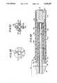
- FIG. 1is a side view of ultrasonic transmission apparatus in accordance with the present invention
- FIG. 1Aillustrates the transmitter of the present invention
- FIG. 1Bis a graphical representation of the relationship between displacement and length of the transmitter of FIG. 1A;
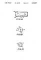
- FIG. 2is a sectional view of the sleeve, protective sheath and fluid coupling channel in the vicinity of the proximal end of the ultrasonic transmission apparatus shown in FIG. 1;
- FIGS. 3A-3Dare views of respective portions of the flexible connector and tip of the ultrasonic transmission apparatus
- FIG. 4is a schematic illustration of an ultrasonic system ready for use by a physician
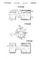
- FIGS. 5A-5Care respective views of the base member that may be used with the ultrasonic transmission apparatus of the present invention.
- FIGS. 6A and 6Billustrate one embodiment of the tip that may be used with the present invention and FIG. 6C illustrates an alternative thereto; and
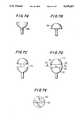
- FIGS. 7A-7Killustrate various alternative embodiments of the tip that may be used with the present invention.
- FIG. 1there is illustrated a preferred embodiment of ultrasonic transmission apparatus in accordance with the present invention.
- this apparatusis shown and described herein in the environment of an ultrasonic angioplasty device readily adapted to be guided into a lumen of a patient, referred to generally herein as the patient's blood vessel, for the purpose of destroying a thrombus therein.
- the ultrasonic transmission apparatus disclosed hereinadmits of different applications and need not be limited solely to coronary thrombosis angioplasty or even to medical applications.
- ultrasonic transmission apparatus 10is comprised of a horn 12, a transmitter 14, a tip 18 and a flexible connector 20 for connecting tip 18 to transmitter 14.
- FIG. 1also illustrates surrounding tubing in which the ultrasonic transmission apparatus is disposed. The purpose and construction of this tubing is described hereinbelow.
- a desirable objective of ultrasonic transmission apparatus 10is to generate reciprocating movement of tip 18 along the longitudinal axis of the ultrasonic transmission apparatus, referred to as longitudinal displacement of the tip.
- the apparatushas been designed to provide maximum displacement of tip 18 while requiring minimal input energy to achieve that displacement.
- desirable tip displacementis on the order of about 20 ⁇ to 60 ⁇ peak-to-peak, at ultrasonic frequencies, and in one application, this displacement is about 30 ⁇ .
- the overall length of the apparatus from the proximal end of horn 12 to tip 18 disposed at the distal end of the ultrasonic transmission apparatusgenerally is in the range of 100 to 150 cm., and for most patients, this length is about 140 cm for intracoronary procedures. In other applications, this length may be shorter or greater.
- transmitter 14is constructed of a material having a very high mechanical Q, such as on the order of 50,000 or greater.
- a suitable materialis aluminum or an aluminum alloy, such as AL-7075, AL-2024, AL-6061, duralumin and hiduminium, as disclosed in copending application Ser. No. 449,465.
- transmitter 14is formed of multiple horn segments distributed along the length thereof.
- the horn segmentsneed not exhibit equal lengths, and a thicker segment provides less attenuation than a thinner segment.
- segments that are substantially straightthat is, where the diameter at the proximal end thereof is equal to the diameter at the distal end, are interspersed with the horn segments.
- the length of each straight segmentis equal to a multiple of ⁇ /2; and it is seen in FIG.
- horn segments 16aalternate with straight segments 16b.
- Such alternation of horn and straight segmentsresults in what is referred to herein as a regular distribution of horn segments along the length of transmitter 14.
- the length of a horn segment 16aneed not be equal to the length of an adjacent straight segment 16b; and it will be appreciated that segments 16b need not necessarily be straight.
- the lengths of the horn and straight segments 16a and 16b at the proximal end of the transmittermay be longer than at the distal end because the larger diameter of these segments at the proximal end provides less displacement loss. Also, since the longer, thicker segments are less flexible, it is preferable in coronary applications for the distal end of the transmitter to be more flexible and thus follow the turns of the patient's blood vessel.
- each horn segment 16aacts as a transformer analogous to an electrical transformer and functions to increase the displacement produced in response to a given level of input ultrasonic energy.
- a graphical representation of the manner in which the displacement along the length of transmitter 14 varies in response to a given input ultrasonic energy levelis shown in FIG. 1B. Whereas each horn segment 16a tends to increase the displacement that may be produced in response to this input energy level, each interspersed, or straight segment 16b simply attenuates that displacement.
- the displacement at the distal end of the transmittermay be reduced relative to the displacement that may be produced at its proximal end, but it will be seen that this reduction, or attenuation, is far less than would otherwise be achieved if transmitter 14 was of constant, uniform cross-sectional dimension, as represented by the attenuation characteristic in FIG. 1B.
- ultrasonic transmission apparatus 10Since ultrasonic transmission apparatus 10 is intended to be used in a patient's blood vessel, its design is subject to inherent constraints. For example, the thickness or cross-sectional diameter, of transmitter 14 must be sufficient to be placed within the patient's blood vessel, and in particular, the transmitter must be thin enough to be disposed within a guide catheter.
- transmitter 14cannot be so thick as to be too rigid and thus not capable of following the normal turns and bends of a blood vessel.
- a very thin transmitterwould satisfy the need for a flexible device that passes easily within the patient's blood vessel, a thin transmitter of constant cross-sectional diameter results in unacceptable attenuation of the ultrasonic displacement, thus requiring a much higher level of input ultrasonic energy to produce a desired displacement.
- the amount of input energy which is needed for a thin transmitter of constant cross-sectional diameter to achieve the desired tip displacementgenerates heat which is harmful and presents a serious risk of injury to the patient.
- a material such as aluminumalthough exhibiting a desirably high mechanical Q is relatively brittle; and the tensile stress exerted by its ultrasonic displacement in combination with the need for a thin transmitter to follow the turns and bends of a blood vessel may result in fracture of the transmitter.
- diameter D 1 at the proximal end of the first horn segment 16ais on the order of about 1.6 mm and diameter D 2 at the distal end of transmitter 14 is on the order of about 0.63 mm.
- a transmitter formed of a single horn-shaped configuration whose overall length is a multiple of ⁇ /2may be used, such as a single, continuously tapered member of 100- 150 cm in length, this single horn segment does not provide attenuation characteristics as favorable as the preferred embodiment formed of horn and straight segments distributed substantially regularly along the length of the transmitter.
- transmitter 14is of integral one-piece construction; and may be machined from a single block of material or, alternatively, may be extruded.
- horn 12is coupled to the proximal end of transmitter 14 and, in the preferred embodiment, the horn and transmitter are of integral one-piece construction. Alternatively, however, the transmitter may be otherwise secured to the horn, as by a suitable adhesive, welding, screw or other mechanical means normally used to connect components in an ultrasonic device.
- Horn 12is provided with a hand piece connector 24 at its proximal end for receiving and coupling thereto a hand piece, such as hand piece 86 shown in FIG. 4.
- This hand pieceincludes a conventional transducer to convert electrical energy to ultrasonic acoustic energy and thereby drive horn 12.
- horn 12is provided with a pair of annular shoulders 26 disposed at an ultrasonic displacement node (that is, the displacement node is located between shoulders 26), these shoulders being adapted to receive an O-ring, such as O-ring 44 shown in FIG. 2, for providing a fluid-tight seal in a fluid supply channel 28, as will be described.
- O-ring 44shown in FIG. 2
- the distal end of the transmitteris coupled to tip 18 by flexible connector 20.
- flexible connector 20should exhibit high flexibility, yet it should be strong enough to withstand internal stress created by the transmission of ultrasonic energy therethrough.
- each wireis less than the cross-sectional diameter D 2 of the distal segment included in transmitter 14.
- the diameters of the titanium wiresare uniform, and the diameter D 3 of each titanium wire is on the order of about 0.27 mm.
- each of these titanium wiresis secured directly to the end face of the distal segment included in transmitter 14, or, alternatively, is integrally formed with the distal segment of the transmitter.
- each wireis configured as a horn to act as a transformer for the ultrasonic displacement transferred thereto.
- a base member 22is used to connect the titanium wires to the transmitter.
- the base membermay be formed of the same material as transmitter 14 and as will be described in greater detail in FIG. 5, includes a central recess 92 (see FIG. 5A) to receive the distal segment of transmitter 14, and also includes a plurality of recesses 94a, 94b , . . . to receive respective ones of the connector wires.
- central recess 92 of base member 22exhibits uniform diameter D 2 to receive distal segment 16b, which is a straight segment.
- the length of this distal segment and, thus, the length of recess 92,is less than ⁇ /2. Accordingly, it will be appreciated from FIG. 1 that the last segment 16a upstream of base member 22 is a horn segment to act as an ultrasonic displacement transformer.
- Distal segment 16b(as best seen in FIG. 1A) which is inserted into recess 92 of base member 22, is of minimal length sufficient to provide a mechanically secure connection of the base member to transmitter 14.
- this distal segment 16b and the titanium wiresattenuate the ultrasonic displacement, it is desirable to minimize the total length of this distal segment and the titanium wires.
- Lthe length of flexible connector 20
- the length of base member 22is represented as L b
- the length of tip 18is represented as L t (as shown in FIG. 1)
- L+L b +L tk ⁇ '/2, where k is an integer and ⁇ ' is the effective wavelength in the section formed of the base member (described herein as aluminum), the flexible connector (described as titanium) and the tip (described as aluminum).
- this effective wavelengthis determined primarily by the wavelength in aluminum and the wavelength in titanium.
- the wires comprising flexible connector 20will bend to follow the configuration of the blood vessel in which the apparatus is used. Consequently, contact between adjacent wires is likely. Such contact produces unwanted damping of ultrasonic displacement and the generation of excessive heat. Accordingly, to prevent such contact, the titanium wires are isolated from each other, and in one embodiment, this is achieved by disposing the wires in respective tubular channels which may be formed of, for example, individual flexible tubes or, alternatively, a multi-channel (or multi-lumen) conduit. Such tubes or tubular channels may be formed of plastic, rubber or other conventional flexible material normally used in medical applications.
- tubes or tubular channelsprovide not only mechanical isolation of the wires but also enable fluid to flow therethrough for the purpose of reducing the ultrasonic load on the transmitter, as well as preventing backflow of blood through the conduit in which the transmitter is disposed.
- This fluidsuch as saline, reduces transverse vibration of the connector wires and provides lubrication for longitudinal displacement of the wires. Further description of flexible connector 20 is described in conjunction with FIGS. 3A-3D.
- Tip 18is reciprocally driven at ultrasonic frequencies for the desirable objective of creating cavitation in the patient's blood vessel.
- cavitationtends to dislodge dead red blood cells which are trapped in the fiber matrix of the thrombus, thus dispersing the thrombus and eliminating the blockage.
- the released red blood cellsare returned harmlessly to the patient's blood stream and the fibers are destroyed.
- cavitationmay not be of significant importance and the tip will be suitably shaped.
- tip 18is configured to have increased surface area.
- a preferred embodiment of the tipis illustrated in FIGS. 6A, 6B and 6C, and other embodiments are shown in FIGS. 7A-7K.
- the preferred embodiment of tip 18includes a proximal portion connected to the wires included in flexible connector 20, a distal portion having, preferably, a concave face, and an intermediate portion which connects the proximal and distal portions and which exhibits a thickness less than the diameter of either the proximal portion or the distal portion.
- the distal portion of tip 18in addition to having a concave face, is of a substantially truncated semi-spheroid shape, whereas the proximal portion is generally cylindrical.
- transmitter 14is disposed in sleeve 40 which provides a channel for fluid to flow about the transmitter.
- Sleeve 40is formed of flexible material, such as rubber, plastic or other suitable material commonly used in catheters for medical applications.
- the distal end of sleeve 40is coupled to the tubular channels that surround the wires of flexible connector 20. This coupling may be achieved by an adhesive, by thermal bonding, or by other conventional means for providing a fluid tight connection of the sleeve to the tubular channels.
- Sleeve 40also provides containment for transmitter 14 in the unlikely event that the transmitter fractures. Hence, the sleeve reduces risk of injury to the patient and facilitates rapid or emergency removal of the ultrasonic transmission apparatus from the patient's blood vessel.
- the proximal end of sleeve 40is coupled to protective sheath 38 with a fluid tight bond.
- the protective sheathprovides a continuation of the fluid channel which surrounds transmitter 14.
- protective sheath 38should be formed of material which is sufficiently strong as not to deform when grasped by a physician. It will be appreciated that when the illustrated ultrasonic transmission apparatus is advanced in a patient's blood vessel, there is a tendency for the physician or technician to grasp the proximal end of transmitter 14 for guiding the transmitter surely and stably. It is likely that the physician would contact a portion of the transmitter at a location other than a vibration node; and such contact would substantially damp the ultrasonic vibrations of the transmitter.
- protective sheath 38performs a dual function, namely, it is included in the fluid conduit which surrounds transmitter 14, and it also provides protection against the damping of ultrasonic vibrations due to contact of the transmitter by the physician. It will be seen that the length of protective sheath 38 should be such that it ends at an ultrasonic vibration node.
- its lengthpreferably should be short because its rigidity reduces the flexibility of the transmitter, but nevertheless should be sufficient to permit the physician to advance the transmitter by an amount which moves tip 18 out of a guiding catheter with which the transmitter may be used and into proximity with a thrombus.
- Spacers 37may be provided on transmitter 14 at displacement nodes to prevent sheath 38 from contacting the transmitter even if the sheath is deformed by the physician. These spacers may be shoulders formed on the transmitter, as shown in FIG. 2
- the transmitterin normal use, is inserted into and moved through a guide catheter of standard length.
- the guide catheteris provided with one or more hemostasis valves, located at positions such that these valves contact protective sheath 38 just as tip 18 emerges from the distal end of the guide catheter. At this location, the tip is spaced from the thrombus or obstruction. It is expected that the physician will advance the transmission apparatus to bring tip 18 adjacent to or in contact with the obstruction, and then he will energize the ultrasonic transmission apparatus. Thus, the transmitter is moved further into the guide catheter and the length of sheath 38 should be at least equal to this distance over which the transmitter is moved.
- the proximal end of protective sheath 38is in fluid communication with a suitable fluid source supplied thereto by a Y-shaped coupling channel 30.
- coupling channel 30is disposed about at least the distal portion of horn 12 and is coupled to protective sheath 38 by an input conduit 36.
- a syringe connector 32functions to connect a syringe or other suitable source of fluid to coupling channel 30.
- fluidmay flow from the fluid source to syringe connector 32, to coupling channel 30 and through input conduit 36 to protective sheath 38.
- Horn 12exhibits an exponentially tapered profile and coupling channel 30 is secured in a fluid-tight manner to the horn.
- Such fluid-tight connectionis provided by a cap 34 which cooperates with coupling channel 30 and O-ring 44 to achieve a fluid-tight seal.
- coupling channel 30may be a conventional hemostatic adapter.
- FIG. 2illustrates, in greater detail, the fluid conduit that surrounds transmitter 14 for supplying fluid from a suitable source to the transmitter.
- a portion of sleeve 40is illustrated, and the proximal end of the sleeve is secured to the distal end of protective sheath 38.
- the outer diameter of the proximal portion of sleeve 40is adhesively secured to the inner diameter of the distal portion of the protective sheath.
- the protective sheathextends over one or more segments or transmitter 14 and preferably ends at a displacement node.
- coupling channel 30includes a fluid supply channel 32 which, as previously referenced and as shown more particularly in FIG. 4, is connected to a syringe 84 by means of a luer lock connector 48.
- fluid from the syringe or, alternatively, any other desired fluid sourceis supplied to sleeve 40 by way of luer lock connector 48, fluid supply channel 32, coupling channel 30, input conduit 36 and protective sheath 38.
- FIG. 2clearly illustrates O-ring 44 disposed at the location defined by annular shoulders 26 on horn 12.
- Coupling channel 30includes a stepped inner diameter which forms a ledge disposed against O-ring 44.
- the O-ringis sandwiched between this ledge and an annular spacer 46 that is positioned about horn 12 and is disposed within coupling channel 30.
- the proximal end of the coupling channelis provided with screw threads that mate with cap 34, the latter having a neck which extends within the coupling channel into contact with spacer 46. It is seen that coupling channel 30, input conduit 36, O-ring 44, spacer 46 and cap 34 all are coaxial with the longitudinal axis of horn 12.
- FIGS. 3A-3Dthe construction of flexible connector 20 and the manner in which the flexible connector joins tip 18 to transmitter 14 are shown in greater detail.
- FIG. 3Ais a magnified side view of flexible connector 20
- FIG. 3Bis a sectional view of tip 18 taken along section lines B--B of FIG. 3A
- FIG. 3Cis a sectional view of the flexible connector taken along section lines C--C of FIG. 3A
- FIG. 3Dis a sectional view of FIG. 3A.
- the flexible connectoris comprised of four wires 50a, 50b, 50c and 50d, although any other desired number of wires may be used, such as three, five, etc.
- the wires 50a-50dare symmetrically arranged, and each wire is surrounded by a flexible tube 54a, 54b, 54c and 54d, respectively.
- a single multi-lumen conduitmay be used as an alternative, as mentioned above.
- the tubular channels which surround wires 50a-50dwill be described as individual, flexible tubes.
- Wires 50a-50dexhibit high tensile strength to minimize the likelihood of fracture due to fatigue or stress.
- a desirable material from which the wires may be formedis titanium.
- the wiresmay be sufficiently thin so as to follow easily the bends of a blood vessel, but because of the high tensile strength thereof, such wires are quite strong. Nevertheless, and as described above, to minimize the risk of tip 18 breaking away from transmitter 14, a plurality of such wires is used.
- the use of plural wiresincreases the level of ultrasonic energy that can be transmitted, thus reducing the input energy level that need be supplied to the transmitter for a desired tip displacement. It will be seen in FIG. 3D, and will be described further below in connection with FIG. 5, that the proximal ends of wires 50a-50d are secured to base member 22 and the distal ends of these wires are secured to tip 18.
- a central guide wire conduit 56is included in flexible connector 20.
- a guide wirefirst is inserted through the vessel lumen, and the ultrasonic transmission apparatus is threaded onto this guide wire so as to be guided therealong through the lumen.
- tip 18is provided with a central conduit, and guide wire conduit 56 extends into this central conduit and through flexible connector 20.
- FIG. 3Dbest illustrates the positioning of this guide wire conduit
- FIG. 3Cshows that guide wire conduit 56 is symmetrical with wires 50a-50d and their respective flexible tubes 54a-54d.
- the proximal end of guide wire conduit 56terminates near the proximal ends of flexible tubes 54a-54d, as seen in FIG. 3D, to facilitate the emergence of guide wire 58 from the flexible connector.
- the guide wirebe external to sleeve 40 and protective sheath 38.
- FIG. 3Dalso illustrates the proximal ends of each of flexible tubes 54a-54d being adhesively secured in fluid-tight relation to sleeve 40.
- the sleevesurrounds all of the flexible tubes; and FIG. 3D illustrates that the proximal ends of the flexible tubes may be provided with a shoulder for receiving and securing the distal end of the sleeve.
- Tip 18is illustrated as having a distal portion 66 of a truncated semi-spheroid shape.
- the tipalso includes a proximal portion, which is illustrated as being substantially cylindrical, with an intermediate portion 70 connecting distal portion 66 to proximal portion 68.
- FIGS. 3A, 3B and 3Dshow that the thickness of intermediate portion 70 is less than the diameters of distal portion 66 and proximal portion 68.
- the surface area of tip 18is increased, particularly in the direction normal to the direction of displacement, by reason of the discontinuity therein presented by intermediate portion 70.
- This discontinuitycreates a cavitation surface 72 on proximal portion 68 and an opposite, facing cavitation surface 78 on distal portion 66.
- Other examples of tip configurations having cavitation surfacesare illustrated in FIGS. 6C and 7A-7K.
- proximal portion 68is provided with recesses 76a, 76b, 76c and 76d adapted to receive and secure the distal ends of wires 50a, 50b, 50c and 50d. It is recognized, therefore, that the diameter of recesses 76a-76d is substantially equal to the outer diameter of wires 50a-50d, respectively.
- the wiresmay be adhesively secured within recesses 76a-76d; and it will be appreciated that other conventional means may be used to affix the wires to proximal portion 68.
- FIG. 3Dalso illustrates the proximal ends of wires 50a-50d being secured within corresponding recesses of base member 22, with the base member including a central recess in which distal segment 16b of transmitter 14 is secured.
- base member 22functions to connect transmitter 14 to flexible connector 20.
- wires 50a-50dlikewise are displaced reciprocally, thereby driving tip 18 at ultrasonic frequencies. Cavitation is produced by the ultrasonic displacement of the tip to destroy a thrombus in the patient's blood vessel.
- FIG. 4there is illustrated an embodiment of an ultrasonic system incorporating the ultrasonic transmission apparatus of the present invention which is seen to be connected to an ultrasonic energy source 88 and to a fluid supply syringe 84.
- a handpiece 86is secured to handpiece connector 24 of horn 12 (FIG. 1) and an electrical connector extends from ultrasonic energy source 88 to the handpiece.
- the handpieceincludes an acoustic transducer and is energized by energy source 88 to supply ultrasonic energy to the horn of the transmitter, thereby driving tip 18.
- FIG. 1an acoustic transducer
- FIG. 4also illustrates guide wire 58 on which tip 18 and flexible connector 20 are threaded, the guide wire serving to guide the advancement of the ultrasonic transmission apparatus through the patient's blood vessel to the vicinity of a thrombus that is to be removed.
- ultrasonic energy source 88is deactivated when the illustrated ultrasonic transmission apparatus is threaded onto guide wire 58 and advanced therealong through the patient's blood vessel. Hence, during this advancement of the apparatus, the physician may grasp any portion of transmitter 14 without any adverse affect.
- ultrasonic energy source 88When tip 18 is disposed in the vicinity of the thrombus to be removed, as will be observed by conventional fluoroscopic techniques known to those of ordinary skill in the art, ultrasonic energy source 88 is activated. In the preferred embodiment, ultrasonic energy is transmitted at a frequency in the range of 40 kHz to 60 kHz, and in the application described herein, this frequency may be about 45 kHz, resulting in reciprocal displacement of tip 18 on the order of 20 ⁇ to 60 ⁇ peak-to-peak, and in the described application, about 30 ⁇ . At this time, the physician should not grasp any of segments 16a, 16b directly. It is appreciated that such direct contact of the physician's fingers with these segments will produce substantial damping of the ultrasonic displacement.
- the physicianmay hold transmitter 14 to provide steady and stable guiding thereof as he advances tip 18 toward the thrombus while the tip is being ultrasonically displaced. It is expected that, by grasping protective sheath 38, the physician will advance transmitter 14 until tip 18 is proximate the thrombus; and as mentioned above, the length of the sheath is sufficient to accommodate this advance. Continued ultrasonic vibration of the tip produces cavitation that destroys the thrombus, and the danger of releasing the thrombus, or a significant portion thereof, to travel through the patient's circulatory system is minimized.
- tip designinfluences the flow pattern of fluid adjacent the thrombus, such as the patient's blood, saline supplied from syringe 84 (as an example of a suitable source) or a mixture thereof.
- tip 18is configured to enhance cavitation and to draw the thrombus toward the tip.
- cavitationmay be merely incidental and the tip is designed accordingly.
- the distal portion of the ultrasonic transmission apparatusis readily capable of following the bends of the patient's blood vessel.
- the use of thin, flexible wires of high tensile strengthminimizes the risk of fracture, minimizes the risk that tip 18 will break away from transmitter 14 and improves the ultrasonic energy transmission characteristics of the connector.
- transmitter 14of high-Q material, the attenuation of ultrasonic displacement is minimized and, advantageously, minimal heat is generated.
- the use of multiple horns distributed along transmitter 14amplifies ultrasonic displacement. Consequently, ultrasonic energy source 88 may exhibit a lower energy level to attain the same displacement of tip 18 than would otherwise be the case if significant attenuation occurred in transmitter 14.
- FIGS. 5A-5Cillustrate a preferred embodiment of base member 22 which is used to connect the distal end of transmitter 14 to flexible connector 20.
- the base memberprovides additional stiffness and provides connections which are selected to be located at a stress node of transmitter 14. Hence, it is desirable to minimize the overall length of the base member and thereby minimize stiffness and maintain the connections at the stress node.
- the length of the base memberis sufficient simply to provide good coupling to the distal segment 16b and good coupling to the proximal ends of wires 50a-50d.
- a central recess 92extends from the proximal end of base member 22 (seen in FIG.
- FIG. 5Bwhich is a distal end view taken along section lines B--B
- wire recesses 94a-94dare provided, each of a diameter D 3 , which is the diameter of each of wires 50a-50d.
- wires 50a-50dare adhesively secured in wire recesses 94a-94d; and distal segment 16b of transmitter 14 likewise is adhesively secured within recess 92.
- other means for affixing the wires and the distal segment to base member 22may be used, such as those means known to those of ordinary skill in the art when interconnecting ultrasonic devices.
- Base member 22which is seen to be cylindrical, preferably is formed of the same material as transmitter 14.
- the base memberis formed of a high mechanical Q material, preferably aluminum or aluminum alloy.
- Recesses 92 and 94a-94dare machined into a solid cylindrical segment, thus resulting in the illustrated base member.
- FIGS. 6A and 6BA preferred embodiment of tip 18, which has been described above, is illustrated in FIGS. 6A and 6B, wherein FIG. 6B is a plan view of proximal portion 68 and FIG. 6A is a partial sectional diagram taken along lines A--A of FIG. 6B.
- the tipis configured to enhance cavitation, although other designs that produce incidental cavitation can be used with the ultrasonic transmission apparatus of the present invention for different applications.
- distal portion 66includes a truncated semi-spheroid shape 74; and the distal portion and proximal portion 68 both are cylindrical.
- Intermediate portion 70whose thickness is less than the diameter of either the distal portion or the proximal portion, is provided as a connecting member therebetween.
- each of these cavitation surfacesis substantially perpendicular to longitudinal axis 102 of tip 18.
- the tipincludes a center bore 104 which extends through the distal, intermediate and proximal portions thereof and is adapted to receive aforedescribed guide wire conduit 56 or to serve as a conduit for guide wire 58 (not shown).
- proximal portion 68is provided with recesses 76a-76d to receive wires 50a-50d, respectively, of flexible connector 20. As these wires undergo ultrasonic displacement in the direction of longitudinal axis 102, tip 18 is driven at the same ultrasonic frequency to produce cavitation in the patient's blood vessel, or in any other fluid in which the ultrasonic transmission apparatus is disposed.
- the tipis driven at an ultrasonic frequency in the range of about 40 kHz to 60 kHz because this frequency permits the tip to be reciprocally driven with a displacement in the range of 20 ⁇ to 60 ⁇ peak-to-peak without significant attenuation in flexible connector 20 due to sharp bends therein as transmitter 14 follows such bends in the patient's blood vessel.
- the tipmay be driven by operating energy source 88 (FIG. 4) in a pulsed mode to prevent the accumulation of, for example, fibrin particles in tip 18 when a thrombus is destroyed.
- FIG. 6Cillustrates a modified version of the tip shown in FIGS. 6A and 6B, in which the distal portion is substantially cylindrical and includes a concave face 80 which serves as yet an additional cavitation surface.
- FIGS. 7A-7Killustrate other embodiments of tip 18 which provide sufficient cavitation when the tip is driven at ultrasonic frequencies, whereby a thrombus is destroyed.
- FIG. 7Aillustrates a so-called reverse mushroom shape, wherein the front face of the tip is substantially planar, and the proximal portion thereof is semi-spheroid in shape.
- FIG. 7Billustrates a mushroom shape 108, which is seen to be the inverse, or complement, of reverse mushroom shape 106 of FIG. 7A.
- FIG. 7Cillustrates a double mushroom shape 110, wherein the embodiments of FIGS. 7A and 7B are interconnected by an intermediate portion to provide two cavitation surfaces similar to aforedescribed cavitation surfaces 72 and 78 of FIG. 6A.
- FIG. 7Dillustrates another embodiment of a double mushroom shape wherein a distal semi-spheroid shape 112 is coupled to an oppositely disposed semi-spheroid shape by an intermediate section 116.
- FIG. 7Ewhich is taken along section lines E--E of FIG. 7D shows that the thickness of intermediate section 116 is less than the diameter of, for example, distal semi-spheroid shape 112.
- two cavitation surfaces 113 and 114are provided on the distal and proximal sections, respectively.
- the effect of the tip configuration shown in FIGS. 7D and 7Eis substantially the same as that of the tip configuration shown in FIG. 6A.
- FIG. 7Fillustrates a double mushroom configuration having a mushroom-shaped distal section 118 and a mushroom-shaped proximal section 122 with an intermediate section 120 disposed therebetween.
- the intermediate sectionmay be disk-shaped and a center post 124 is used to connect distal section 118, intermediate section 120 and proximal section 122, as illustrated.
- four cavitation surfacesare provided, one on distal section 118, one on proximal section 122 and two on intermediate section 120.
- FIGS. 7G-7Iillustrate yet another embodiment of tip 18, wherein a distal section 126 that is substantially mushroom-shaped is connected to a distal cavitation portion 132 by means of a connecting section 130.
- FIG. 7Iwhich is taken along section lines I--I in FIG. 7G, illustrates connecting section 130 as a relatively thin web whose thickness is less than the diameter of distal section 126, and FIG. 7I further illustrates that distal cavitation portion 132 is substantially disk-shaped. It is seen that a cavitation surface 128 is provided on distal section 126 and a cavitation surface 129 is provided on distal cavitation portion 132.
- Distal cavitation portion 132is coupled to a reverse mushroom-shaped proximal section 138 by means of an intermediate section 134, which is shown in approximate proportion in FIG. 7H, taken along section lines H--H of FIG. 7G. It is seen that intermediate section 134 is a relatively thin web similar to the thin web of connecting section 130, and rotated by about 90° with respect thereto. The thickness of intermediate section 134 is less than the diameter of proximal section 138. Accordingly, cavitation surface 136 is provided on proximal section 138 and a cavitation surface 135 is provided on distal cavitation portion 132 in facing relation thereto. In the embodiment shown in FIGS.
- FIGS. 7G-7Ifor cavitation surfaces are provided, one on distal section 126, two on distal cavitation portion 132 and one on proximal section 138.
- the cavitation effect produced by the tip shown in FIGS. 7G-7Iis substantially similar to the cavitation effect produced by the tip shown in FIG. 7F.
- FIG. 7Jillustrates yet another embodiment of a tip having an increased surface for producing cavitation.
- the tipis shown as an elongated semi-spheroid shape 140 having a notch 142 in the central portion thereof, resulting in a discontinuity in the exterior surface to define cavitation surfaces 144 and 146.
- FIG. 7Kis taken along section lines K--K of FIG. 7J and illustrates the shape of cavitation surface 146. It will be appreciated that cavitation surface 144 is substantially similar in shape.
- Transmitter 14connector 20 and tip 18 were inserted into an anatomic model leading to the left anterior descending (LAD) coronary artery. Puncture site was at the femoral artery and tip 18 reached the LAD by way of a 9-French Judkins left coronary guide catheter. Tip displacement was observed and measured by conventional video magnification, with the following results:
- the embodiment of the present inventionwas 126 cm in overall length, and transmitter 14 was formed with four horn segments distributed along its length and interspersed with straight segments.
- the diameter D 1 of the transmitter at its proximal endwas 1.6 mm and the diameter D 2 of the transmitter at its distal end was 0.5 mm.
- the apparatus to which the present invention was comparedwas formed of a wire 125.5 cm long of constant, uniform diameter of 0.5 mm along its entire length (referred to herein as the "straight wire transmitter"). Both transmitters were coupled to horns (such as horn 12) of substantially the same profile and both transmitters were energized at about 28.5 kHz.
- a model A-200A Branson Horn Analyzerwas used for testing.
- the flexibility of the tip connected to transmitter 14 by connector 20 of the present inventionwas compared to the flexibility of the tip of the straight wire transmitter by measuring the force needed to deflect the tip by 1 mm. For this comparison the transmitter was clamped near its distal end such that the distance from the clamp to the center of gravity of the tip was 1.3 cm.
- the connectorwas formed of four titanium wires, each of 0.25 mm diameter and the straight wire transmitter had a diameter of 0.5 mm.
- the cross-sectional areasthat is, the cross-sectional area of the four titanium wires and the cross-sectional area of the straight wire transmitter
- the bending force needed to achieve a 1 mm tip deflection of the present inventionwas 7 grams and the bending force needed to achieve a l mm tip deflection of the straight wire transmitter was 35 grams.
- Thrombolysis efficacy of the ultrasonic transmission apparatuswas tested empirically on samples of bovine thrombus placed in the LAD. Thrombolysis commenced with input power set at 12 watts and became more consistent once this input power reached 14 watts. The time needed for the apparatus to clear a lesion varied with different thrombus samples from about 5 seconds to more than 60 seconds. The effect of drawing the thrombus to tip 18 was clearly observed, even with flow in the LAD of about 10 to 20 ml/min.
- the tips shown in FIGS. 7A-7Kmay be provided with a concave face at the distal end thereof.
- the tipexhibit an increase in surface area so as to provide optimum cavitation for destroying thrombi. Nevertheless, in different applications of the present invention, the tip will be configured so as not to generate substantial cavitation.
Landscapes
- Health & Medical Sciences (AREA)
- Engineering & Computer Science (AREA)
- Surgery (AREA)
- Mechanical Engineering (AREA)
- Life Sciences & Earth Sciences (AREA)
- Biomedical Technology (AREA)
- Nuclear Medicine, Radiotherapy & Molecular Imaging (AREA)
- Vascular Medicine (AREA)
- Orthopedic Medicine & Surgery (AREA)
- Heart & Thoracic Surgery (AREA)
- Medical Informatics (AREA)
- Molecular Biology (AREA)
- Animal Behavior & Ethology (AREA)
- General Health & Medical Sciences (AREA)
- Public Health (AREA)
- Veterinary Medicine (AREA)
- Surgical Instruments (AREA)
- Media Introduction/Drainage Providing Device (AREA)
Abstract
Description
______________________________________ Input Power Displacement (microns) ______________________________________ 8 watts 17.2 peak-to-peak 10 20.0 12 25.7 14 31.5 16 34.3 18 38.6 ______________________________________
Claims (51)
Priority Applications (9)
| Application Number | Priority Date | Filing Date | Title |
|---|---|---|---|
| US07/842,529US5269297A (en) | 1992-02-27 | 1992-02-27 | Ultrasonic transmission apparatus |
| CA002128006ACA2128006C (en) | 1992-02-27 | 1993-01-26 | Ultrasonic transmission apparatus |
| EP98120505AEP0891744A1 (en) | 1992-02-27 | 1993-01-26 | Ultrasonic transmission apparatus |
| PCT/US1993/000764WO1993016646A1 (en) | 1992-02-27 | 1993-01-26 | Ultrasonic transmission apparatus |
| JP5514860AJP2670715B2 (en) | 1992-02-27 | 1993-01-26 | Ultrasonic transmitter |
| EP93904699AEP0627897A4 (en) | 1992-02-27 | 1993-01-26 | Ultrasonic transmission apparatus. |
| IL11763793AIL117637A (en) | 1992-02-27 | 1993-02-25 | Tip for ultrasonic transmission apparatus |
| IL10486093AIL104860A (en) | 1992-02-27 | 1993-02-25 | Ultrasonic transmission apparatus |
| IL11763796AIL117637A0 (en) | 1992-02-27 | 1996-03-24 | A tip for ultrasonic transmission apparatus |
Applications Claiming Priority (1)
| Application Number | Priority Date | Filing Date | Title |
|---|---|---|---|
| US07/842,529US5269297A (en) | 1992-02-27 | 1992-02-27 | Ultrasonic transmission apparatus |
Publications (1)
| Publication Number | Publication Date |
|---|---|
| US5269297Atrue US5269297A (en) | 1993-12-14 |
Family
ID=25287552
Family Applications (1)
| Application Number | Title | Priority Date | Filing Date |
|---|---|---|---|
| US07/842,529Expired - Fee RelatedUS5269297A (en) | 1992-02-27 | 1992-02-27 | Ultrasonic transmission apparatus |
Country Status (6)
| Country | Link |
|---|---|
| US (1) | US5269297A (en) |
| EP (2) | EP0627897A4 (en) |
| JP (1) | JP2670715B2 (en) |
| CA (1) | CA2128006C (en) |
| IL (1) | IL104860A (en) |
| WO (1) | WO1993016646A1 (en) |
Cited By (287)
| Publication number | Priority date | Publication date | Assignee | Title |
|---|---|---|---|---|
| US5380274A (en)* | 1991-01-11 | 1995-01-10 | Baxter International Inc. | Ultrasound transmission member having improved longitudinal transmission properties |
| US5397293A (en)* | 1992-11-25 | 1995-03-14 | Misonix, Inc. | Ultrasonic device with sheath and transverse motion damping |
| US5417672A (en)* | 1993-10-04 | 1995-05-23 | Baxter International Inc. | Connector for coupling an ultrasound transducer to an ultrasound catheter |
| US5427118A (en)* | 1993-10-04 | 1995-06-27 | Baxter International Inc. | Ultrasonic guidewire |
| US5447509A (en)* | 1991-01-11 | 1995-09-05 | Baxter International Inc. | Ultrasound catheter system having modulated output with feedback control |
| US5474530A (en)* | 1991-01-11 | 1995-12-12 | Baxter International Inc. | Angioplasty and ablative devices having onboard ultrasound components and devices and methods for utilizing ultrasound to treat or prevent vasospasm |
| US5713916A (en)* | 1996-02-28 | 1998-02-03 | Hewlett Packard Company | Method and system for coupling acoustic energy using shear waves |
| US5722979A (en)* | 1997-04-08 | 1998-03-03 | Schneider (Usa) Inc. | Pressure assisted ultrasonic balloon catheter and method of using same |
| US5725494A (en)* | 1995-11-30 | 1998-03-10 | Pharmasonics, Inc. | Apparatus and methods for ultrasonically enhanced intraluminal therapy |
| US5728062A (en)* | 1995-11-30 | 1998-03-17 | Pharmasonics, Inc. | Apparatus and methods for vibratory intraluminal therapy employing magnetostrictive transducers |
| US5735811A (en)* | 1995-11-30 | 1998-04-07 | Pharmasonics, Inc. | Apparatus and methods for ultrasonically enhanced fluid delivery |
| US5813998A (en)* | 1996-02-28 | 1998-09-29 | Hewlett-Packard Company | Method and system for coupling acoustic energy using an end-fire array |
| WO1998035721A3 (en)* | 1997-02-13 | 1998-10-08 | Angiosonics Inc | Ultrasound transmission apparatus and method of using same |
| WO1998048711A1 (en) | 1997-05-01 | 1998-11-05 | Ekos Corporation | Ultrasound catheter |
| WO1998052478A1 (en) | 1997-05-19 | 1998-11-26 | Angiosonics, Inc. | Cooling system for ultrasound device |
| US5846218A (en)* | 1996-09-05 | 1998-12-08 | Pharmasonics, Inc. | Balloon catheters having ultrasonically driven interface surfaces and methods for their use |
| US5873844A (en)* | 1997-01-22 | 1999-02-23 | Campero; Manuel | Method and apparatus for numbing tissue before inserting a needle |
| WO1999016360A1 (en) | 1997-09-29 | 1999-04-08 | Angiosonics Inc. | Lysis method and apparatus |
| US5916196A (en)* | 1995-05-26 | 1999-06-29 | Schneider (Europe) Ag | Fluid delivery system for a balloon catheter |
| US5931805A (en)* | 1997-06-02 | 1999-08-03 | Pharmasonics, Inc. | Catheters comprising bending transducers and methods for their use |
| WO1999039647A1 (en) | 1998-02-10 | 1999-08-12 | Angiosonics, Inc. | Apparatus and method for inhibiting restenosis by applying ultrasound energy together with drugs |
| US5957882A (en)* | 1991-01-11 | 1999-09-28 | Advanced Cardiovascular Systems, Inc. | Ultrasound devices for ablating and removing obstructive matter from anatomical passageways and blood vessels |
| US5989208A (en)* | 1997-05-16 | 1999-11-23 | Nita; Henry | Therapeutic ultrasound system |
| US6024718A (en)* | 1996-09-04 | 2000-02-15 | The Regents Of The University Of California | Intraluminal directed ultrasound delivery device |
| US6135976A (en)* | 1998-09-25 | 2000-10-24 | Ekos Corporation | Method, device and kit for performing gene therapy |
| US6221038B1 (en) | 1996-11-27 | 2001-04-24 | Pharmasonics, Inc. | Apparatus and methods for vibratory intraluminal therapy employing magnetostrictive transducers |
| US6228046B1 (en) | 1997-06-02 | 2001-05-08 | Pharmasonics, Inc. | Catheters comprising a plurality of oscillators and methods for their use |
| EP0919292A3 (en)* | 1997-11-29 | 2001-05-16 | KOREA INSTITUTE OF MACHINERY & METALS | Ultrasonic generator for minimizing heat input of magnetostrictive element and its manufacturing method |
| US6256859B1 (en) | 1998-09-25 | 2001-07-10 | Sherwood Services Ag | Method of manufacturing an aspiring tool |
| US6264630B1 (en) | 1998-12-23 | 2001-07-24 | Scimed Life Systems, Inc. | Balloon catheter having an oscillating tip configuration |
| US6361531B1 (en) | 2000-01-21 | 2002-03-26 | Medtronic Xomed, Inc. | Focused ultrasound ablation devices having malleable handle shafts and methods of using the same |
| US6409720B1 (en) | 2000-01-19 | 2002-06-25 | Medtronic Xomed, Inc. | Methods of tongue reduction using high intensity focused ultrasound to form an ablated tissue area containing a plurality of lesions |
| US6413254B1 (en) | 2000-01-19 | 2002-07-02 | Medtronic Xomed, Inc. | Method of tongue reduction by thermal ablation using high intensity focused ultrasound |
| US6464660B2 (en) | 1996-09-05 | 2002-10-15 | Pharmasonics, Inc. | Balloon catheters having ultrasonically driven interface surfaces and methods for their use |
| US6551337B1 (en) | 1999-10-05 | 2003-04-22 | Omnisonics Medical Technologies, Inc. | Ultrasonic medical device operating in a transverse mode |
| US6595934B1 (en) | 2000-01-19 | 2003-07-22 | Medtronic Xomed, Inc. | Methods of skin rejuvenation using high intensity focused ultrasound to form an ablated tissue area containing a plurality of lesions |
| US6652547B2 (en) | 1999-10-05 | 2003-11-25 | Omnisonics Medical Technologies, Inc. | Apparatus and method of removing occlusions using ultrasonic medical device operating in a transverse mode |
| US6660013B2 (en) | 1999-10-05 | 2003-12-09 | Omnisonics Medical Technologies, Inc. | Apparatus for removing plaque from blood vessels using ultrasonic energy |
| US20040019318A1 (en)* | 2001-11-07 | 2004-01-29 | Wilson Richard R. | Ultrasound assembly for use with a catheter |
| US20040019266A1 (en)* | 2002-07-29 | 2004-01-29 | Omnisonics Medical Technologies, Inc. | Apparatus and method for radiopaque coating for an ultrasonic medical device |
| US20040024393A1 (en)* | 2002-08-02 | 2004-02-05 | Henry Nita | Therapeutic ultrasound system |
| US6692450B1 (en) | 2000-01-19 | 2004-02-17 | Medtronic Xomed, Inc. | Focused ultrasound ablation devices having selectively actuatable ultrasound emitting elements and methods of using the same |
| US6695782B2 (en) | 1999-10-05 | 2004-02-24 | Omnisonics Medical Technologies, Inc. | Ultrasonic probe device with rapid attachment and detachment means |
| US6695781B2 (en) | 1999-10-05 | 2004-02-24 | Omnisonics Medical Technologies, Inc. | Ultrasonic medical device for tissue remodeling |
| US20040073238A1 (en)* | 1996-02-02 | 2004-04-15 | Transvascular, Inc. | Device, system and method for interstitial transvascular intervention |
| US6730048B1 (en)* | 2002-12-23 | 2004-05-04 | Omnisonics Medical Technologies, Inc. | Apparatus and method for ultrasonic medical device with improved visibility in imaging procedures |
| US6733451B2 (en) | 1999-10-05 | 2004-05-11 | Omnisonics Medical Technologies, Inc. | Apparatus and method for an ultrasonic probe used with a pharmacological agent |
| US20040176686A1 (en)* | 2002-12-23 | 2004-09-09 | Omnisonics Medical Technologies, Inc. | Apparatus and method for ultrasonic medical device with improved visibility in imaging procedures |
| US6855123B2 (en) | 2002-08-02 | 2005-02-15 | Flow Cardia, Inc. | Therapeutic ultrasound system |
| US20050096679A1 (en)* | 2003-11-05 | 2005-05-05 | Stulen Foster B. | Ultrasonic surgical blade and instrument having a gain step |
| US20050283080A1 (en)* | 2003-09-19 | 2005-12-22 | Flowcardia, Inc. | Connector for securing ultrasound catheter to transducer |
| US20060058707A1 (en)* | 2004-09-16 | 2006-03-16 | Guided Therapy Systems, Inc. | Method and system for ultrasound treatment with a multi-directional transducer |
| US20060074355A1 (en)* | 2004-09-24 | 2006-04-06 | Guided Therapy Systems, Inc. | Method and system for combined ultrasound treatment |
| US20060079868A1 (en)* | 2004-10-07 | 2006-04-13 | Guided Therapy Systems, L.L.C. | Method and system for treatment of blood vessel disorders |
| US20060084891A1 (en)* | 2004-10-06 | 2006-04-20 | Guided Therapy Systems, L.L.C. | Method and system for ultra-high frequency ultrasound treatment |
| US20060090956A1 (en)* | 2004-11-04 | 2006-05-04 | Advanced Ultrasonic Solutions, Inc. | Ultrasonic rod waveguide-radiator |
| US20060111744A1 (en)* | 2004-10-13 | 2006-05-25 | Guided Therapy Systems, L.L.C. | Method and system for treatment of sweat glands |
| US20060116671A1 (en)* | 2004-10-06 | 2006-06-01 | Guided Therapy Systems, L.L.C. | Method and system for controlled thermal injury of human superficial tissue |
| EP1119298A4 (en)* | 1998-10-09 | 2006-09-13 | Sound Surgical Tech Llc | Ultrasonic probe and method for improved fragmentation |
| US20070005121A1 (en)* | 2002-04-29 | 2007-01-04 | Rohit Khanna | Central nervous system cooling catheter |
| WO2005118277A3 (en)* | 2004-05-27 | 2007-03-01 | Sulphco Inc | High-throughput continuous-flow ultrasound reactor |
| US20070208253A1 (en)* | 1997-10-14 | 2007-09-06 | Guided Therapy Systems, Inc. | Imaging, therapy and temperature monitoring ultrasonic system |
| US20070260172A1 (en)* | 1999-02-16 | 2007-11-08 | Henry Nita | Pre-shaped therapeutic catheter |
| US20080058682A1 (en)* | 2006-03-09 | 2008-03-06 | Haim Azhari | Device for ultrasound monitored tissue treatment |
| US20080071255A1 (en)* | 2006-09-19 | 2008-03-20 | Barthe Peter G | Method and system for treating muscle, tendon, ligament and cartilage tissue |
| US20080108937A1 (en)* | 2006-11-07 | 2008-05-08 | Henry Nita | Ultrasound catheter having protective feature against breakage |
| US7384407B2 (en) | 2001-12-03 | 2008-06-10 | Ekos Corporation | Small vessel ultrasound catheter |
| US20080194999A1 (en)* | 2007-02-09 | 2008-08-14 | Norihiro Yamaha | Ultrasonic treatment apparatus and treatment method |
| US20080281237A1 (en)* | 2007-05-07 | 2008-11-13 | Guded Therapy Systems, Llc. | Methods and systems for coupling and focusing acoustic energy using a coupler member |
| US20090014377A1 (en)* | 2007-07-12 | 2009-01-15 | Kimberly-Clark Worldwide, Inc. | Ultrasonic treatment chamber having electrode properties |
| US20090048514A1 (en)* | 2006-03-09 | 2009-02-19 | Slender Medical Ltd. | Device for ultrasound monitored tissue treatment |
| US7503895B2 (en) | 1999-10-05 | 2009-03-17 | Omnisonics Medical Technologies, Inc. | Ultrasonic device for tissue ablation and sheath for use therewith |
| US20090168590A1 (en)* | 2007-12-28 | 2009-07-02 | Kimberly-Clark Worldwide, Inc. | Ultrasonic treatment chamber for preparing antimicrobial formulations |
| US20090165223A1 (en)* | 2007-12-27 | 2009-07-02 | Kimberly-Clark Worldwide, Inc. | Process for applying one or more treatment agents to a textile web |
| US20090168591A1 (en)* | 2007-12-28 | 2009-07-02 | Kimberly-Clark Worldwide, Inc. | Ultrasonic treatment chamber for particle dispersion into formulations |
| US20100011236A1 (en)* | 2005-04-25 | 2010-01-14 | Guided Therapy Systems, L.L.C. | Method and system for enhancing computer peripheral safety |
| US20100044452A1 (en)* | 2006-09-08 | 2010-02-25 | Kimberly-Clark Worldwide, Inc. | Ultrasonic liquid treatment and delivery system and process |
| US20100150859A1 (en)* | 2008-12-15 | 2010-06-17 | Kimberly-Clark Worldwide, Inc. | Methods of preparing metal-modified silica nanoparticles |
| US20100152042A1 (en)* | 2008-12-15 | 2010-06-17 | Kimberly-Clark Worldwide, Inc. | Compositions comprising metal-modified silica nanoparticles |
| US7771372B2 (en) | 2003-01-03 | 2010-08-10 | Ekos Corporation | Ultrasonic catheter with axial energy field |
| US7774933B2 (en) | 2002-02-28 | 2010-08-17 | Ekos Corporation | Method of manufacturing ultrasound catheters |
| US20100206742A1 (en)* | 2007-12-05 | 2010-08-19 | Kimberly-Clark Worldwide, Inc. | Ultrasonic treatment chamber for treating hydrogen isotopes |
| US7794414B2 (en) | 2004-02-09 | 2010-09-14 | Emigrant Bank, N.A. | Apparatus and method for an ultrasonic medical device operating in torsional and transverse modes |
| US7818854B2 (en) | 2002-10-14 | 2010-10-26 | Ekos Corporation | Ultrasound radiating members for catheter |
| US20100274161A1 (en)* | 2007-10-15 | 2010-10-28 | Slender Medical, Ltd. | Implosion techniques for ultrasound |
| US20100280420A1 (en)* | 2004-09-16 | 2010-11-04 | Guided Therapy Systems, Llc | System and method for variable depth ultrasound treatment |
| US7914509B2 (en) | 1997-05-01 | 2011-03-29 | Ekos Corporation | Ultrasound catheter |
| US7947184B2 (en) | 2007-07-12 | 2011-05-24 | Kimberly-Clark Worldwide, Inc. | Treatment chamber for separating compounds from aqueous effluent |
| US7955293B2 (en) | 2002-08-26 | 2011-06-07 | Flowcardia, Inc. | Ultrasound catheter for disrupting blood vessel obstructions |
| US7976483B2 (en) | 1997-05-01 | 2011-07-12 | Ekos Corporation | Ultrasound assembly with increased efficacy |
| US20110172530A1 (en)* | 2000-12-28 | 2011-07-14 | Ardent Sound, Inc. | Visual imaging system for ultrasonic probe |
| US20110178444A1 (en)* | 2009-11-24 | 2011-07-21 | Slayton Michael H | Methods and systems for generating thermal bubbles for improved ultrasound imaging and therapy |
| US7993308B2 (en) | 2003-04-22 | 2011-08-09 | Ekos Corporation | Ultrasound enhanced central venous catheter |
| US8034286B2 (en) | 2006-09-08 | 2011-10-11 | Kimberly-Clark Worldwide, Inc. | Ultrasonic treatment system for separating compounds from aqueous effluent |
| US8043251B2 (en) | 2003-01-14 | 2011-10-25 | Flowcardia, Inc. | Ultrasound catheter and methods for making and using same |
| US8057573B2 (en) | 2007-12-28 | 2011-11-15 | Kimberly-Clark Worldwide, Inc. | Ultrasonic treatment chamber for increasing the shelf life of formulations |
| US8062566B2 (en) | 2003-04-08 | 2011-11-22 | Flowcardia, Inc. | Method of manufacturing an ultrasound transmission member for use in an ultrasound catheter device |
| US8143318B2 (en) | 2007-12-28 | 2012-03-27 | Kimberly-Clark Worldwide, Inc. | Ultrasonic treatment chamber for preparing emulsions |
| US8221343B2 (en) | 2005-01-20 | 2012-07-17 | Flowcardia, Inc. | Vibrational catheter devices and methods for making same |
| US8226629B1 (en) | 2002-04-01 | 2012-07-24 | Ekos Corporation | Ultrasonic catheter power control |
| US8226566B2 (en) | 2009-06-12 | 2012-07-24 | Flowcardia, Inc. | Device and method for vascular re-entry |
| US8235909B2 (en) | 2004-05-12 | 2012-08-07 | Guided Therapy Systems, L.L.C. | Method and system for controlled scanning, imaging and/or therapy |
| US8246643B2 (en) | 2006-11-07 | 2012-08-21 | Flowcardia, Inc. | Ultrasound catheter having improved distal end |
| US8366622B2 (en) | 2004-10-06 | 2013-02-05 | Guided Therapy Systems, Llc | Treatment of sub-dermal regions for cosmetic effects |
| US8444562B2 (en) | 2004-10-06 | 2013-05-21 | Guided Therapy Systems, Llc | System and method for treating muscle, tendon, ligament and cartilage tissue |
| US8454889B2 (en) | 2007-12-21 | 2013-06-04 | Kimberly-Clark Worldwide, Inc. | Gas treatment system |
| US20130178790A1 (en)* | 2012-01-05 | 2013-07-11 | Cook Medical Technologies Llc | Infusion catheter |
| US8535228B2 (en) | 2004-10-06 | 2013-09-17 | Guided Therapy Systems, Llc | Method and system for noninvasive face lifts and deep tissue tightening |
| US20130253557A1 (en)* | 2012-03-26 | 2013-09-26 | Dana Llc | Surgical instrument ringing a titanium needle with a node of minimum amplitude in a substantially cylindrical portion of the needle |
| US8613751B2 (en) | 2003-11-24 | 2013-12-24 | Flowcardia, Inc. | Steerable ultrasound catheter |
| US8617096B2 (en) | 2004-08-26 | 2013-12-31 | Flowcardia, Inc. | Ultrasound catheter devices and methods |
| US8616759B2 (en) | 2006-09-08 | 2013-12-31 | Kimberly-Clark Worldwide, Inc. | Ultrasonic treatment system |
| US8623040B2 (en) | 2009-07-01 | 2014-01-07 | Alcon Research, Ltd. | Phacoemulsification hook tip |
| US20140012296A1 (en)* | 2012-07-09 | 2014-01-09 | Glenn Robert Sussmen | Rounded-End Device, System, and Method for Preventing Posterior Capsular Opacification |
| US8636665B2 (en) | 2004-10-06 | 2014-01-28 | Guided Therapy Systems, Llc | Method and system for ultrasound treatment of fat |
| US8663112B2 (en) | 2004-10-06 | 2014-03-04 | Guided Therapy Systems, Llc | Methods and systems for fat reduction and/or cellulite treatment |
| US8690779B2 (en) | 2004-10-06 | 2014-04-08 | Guided Therapy Systems, Llc | Noninvasive aesthetic treatment for tightening tissue |
| US8790359B2 (en) | 1999-10-05 | 2014-07-29 | Cybersonics, Inc. | Medical systems and related methods |
| US8858471B2 (en) | 2011-07-10 | 2014-10-14 | Guided Therapy Systems, Llc | Methods and systems for ultrasound treatment |
| US8857438B2 (en) | 2010-11-08 | 2014-10-14 | Ulthera, Inc. | Devices and methods for acoustic shielding |
| US8858892B2 (en) | 2007-12-21 | 2014-10-14 | Kimberly-Clark Worldwide, Inc. | Liquid treatment system |
| US8915870B2 (en) | 2004-10-06 | 2014-12-23 | Guided Therapy Systems, Llc | Method and system for treating stretch marks |
| US8961423B2 (en) | 2003-02-26 | 2015-02-24 | Flowcardia, Inc. | Ultrasound catheter apparatus |
| US9011337B2 (en) | 2011-07-11 | 2015-04-21 | Guided Therapy Systems, Llc | Systems and methods for monitoring and controlling ultrasound power output and stability |
| US9011336B2 (en) | 2004-09-16 | 2015-04-21 | Guided Therapy Systems, Llc | Method and system for combined energy therapy profile |
| US9107798B2 (en) | 2006-03-09 | 2015-08-18 | Slender Medical Ltd. | Method and system for lipolysis and body contouring |
| US9149658B2 (en) | 2010-08-02 | 2015-10-06 | Guided Therapy Systems, Llc | Systems and methods for ultrasound treatment |
| US9216276B2 (en) | 2007-05-07 | 2015-12-22 | Guided Therapy Systems, Llc | Methods and systems for modulating medicants using acoustic energy |
| US9241683B2 (en) | 2006-10-04 | 2016-01-26 | Ardent Sound Inc. | Ultrasound system and method for imaging and/or measuring displacement of moving tissue and fluid |
| US9263663B2 (en) | 2012-04-13 | 2016-02-16 | Ardent Sound, Inc. | Method of making thick film transducer arrays |
| US9282984B2 (en) | 2006-04-05 | 2016-03-15 | Flowcardia, Inc. | Therapeutic ultrasound system |
| US9283188B2 (en) | 2006-09-08 | 2016-03-15 | Kimberly-Clark Worldwide, Inc. | Delivery systems for delivering functional compounds to substrates and processes of using the same |
| US9326806B2 (en) | 2003-09-02 | 2016-05-03 | Crosstrees Medical, Inc. | Devices and methods for the treatment of bone fracture |
| US9421504B2 (en) | 2007-12-28 | 2016-08-23 | Kimberly-Clark Worldwide, Inc. | Ultrasonic treatment chamber for preparing emulsions |
| US9504446B2 (en) | 2010-08-02 | 2016-11-29 | Guided Therapy Systems, Llc | Systems and methods for coupling an ultrasound source to tissue |
| US9510802B2 (en) | 2012-09-21 | 2016-12-06 | Guided Therapy Systems, Llc | Reflective ultrasound technology for dermatological treatments |
| US20160367275A1 (en)* | 2009-10-06 | 2016-12-22 | Cardioprolific Inc. | Methods and devices for endovascular therapy |
| US9566454B2 (en) | 2006-09-18 | 2017-02-14 | Guided Therapy Systems, Llc | Method and sysem for non-ablative acne treatment and prevention |
| US9694212B2 (en) | 2004-10-06 | 2017-07-04 | Guided Therapy Systems, Llc | Method and system for ultrasound treatment of skin |
| US20170201036A1 (en)* | 2016-01-07 | 2017-07-13 | Dune Medical Devices Ltd. | Composite connector |
| US9827449B2 (en) | 2004-10-06 | 2017-11-28 | Guided Therapy Systems, L.L.C. | Systems for treating skin laxity |
| US20180311703A1 (en)* | 2016-01-07 | 2018-11-01 | Olympus Corporation | Vibration transmitting member and ultrasonic treatment instrument |
| US10258505B2 (en) | 2010-09-17 | 2019-04-16 | Alcon Research, Ltd. | Balanced phacoemulsification tip |
| US10265913B2 (en) | 2016-11-23 | 2019-04-23 | GM Global Technology Operations LLC | Horn for an ultrasonic welding process |
| US10335280B2 (en) | 2000-01-19 | 2019-07-02 | Medtronic, Inc. | Method for ablating target tissue of a patient |
| US10357263B2 (en) | 2012-01-18 | 2019-07-23 | C. R. Bard, Inc. | Vascular re-entry device |
| US10420960B2 (en) | 2013-03-08 | 2019-09-24 | Ulthera, Inc. | Devices and methods for multi-focus ultrasound therapy |
| US10441308B2 (en) | 2007-11-30 | 2019-10-15 | Ethicon Llc | Ultrasonic surgical instrument blades |
| US10463887B2 (en) | 2007-11-30 | 2019-11-05 | Ethicon Llc | Ultrasonic surgical blades |
| US10517627B2 (en) | 2012-04-09 | 2019-12-31 | Ethicon Llc | Switch arrangements for ultrasonic surgical instruments |
| US10531910B2 (en) | 2007-07-27 | 2020-01-14 | Ethicon Llc | Surgical instruments |
| US10537352B2 (en) | 2004-10-08 | 2020-01-21 | Ethicon Llc | Tissue pads for use with surgical instruments |
| US10537304B2 (en) | 2008-06-06 | 2020-01-21 | Ulthera, Inc. | Hand wand for ultrasonic cosmetic treatment and imaging |
| US20200023160A1 (en)* | 2018-05-17 | 2020-01-23 | Route 92 Medical, Inc. | Aspiration catheter systems and methods of use |
| US10561862B2 (en) | 2013-03-15 | 2020-02-18 | Guided Therapy Systems, Llc | Ultrasound treatment device and methods of use |
| US10575892B2 (en) | 2015-12-31 | 2020-03-03 | Ethicon Llc | Adapter for electrical surgical instruments |
| US10582983B2 (en) | 2017-02-06 | 2020-03-10 | C. R. Bard, Inc. | Ultrasonic endovascular catheter with a controllable sheath |
| US10595929B2 (en) | 2015-03-24 | 2020-03-24 | Ethicon Llc | Surgical instruments with firing system overload protection mechanisms |
| US10603521B2 (en) | 2014-04-18 | 2020-03-31 | Ulthera, Inc. | Band transducer ultrasound therapy |
| US10603064B2 (en) | 2016-11-28 | 2020-03-31 | Ethicon Llc | Ultrasonic transducer |
| US10610286B2 (en) | 2015-09-30 | 2020-04-07 | Ethicon Llc | Techniques for circuit topologies for combined generator |
| US10639092B2 (en) | 2014-12-08 | 2020-05-05 | Ethicon Llc | Electrode configurations for surgical instruments |
| US10646269B2 (en) | 2016-04-29 | 2020-05-12 | Ethicon Llc | Non-linear jaw gap for electrosurgical instruments |
| US10646239B2 (en) | 2011-08-05 | 2020-05-12 | Route 92 Medical, Inc. | Methods and systems for treatment of acute ischemic stroke |
| US10656025B2 (en) | 2015-06-10 | 2020-05-19 | Ekos Corporation | Ultrasound catheter |
| US10688321B2 (en) | 2009-07-15 | 2020-06-23 | Ethicon Llc | Ultrasonic surgical instruments |
| US10709906B2 (en) | 2009-05-20 | 2020-07-14 | Ethicon Llc | Coupling arrangements and methods for attaching tools to ultrasonic surgical instruments |
| US10709469B2 (en) | 2016-01-15 | 2020-07-14 | Ethicon Llc | Modular battery powered handheld surgical instrument with energy conservation techniques |
| US10716615B2 (en) | 2016-01-15 | 2020-07-21 | Ethicon Llc | Modular battery powered handheld surgical instrument with curved end effectors having asymmetric engagement between jaw and blade |
| US10722261B2 (en) | 2007-03-22 | 2020-07-28 | Ethicon Llc | Surgical instruments |
| US10729494B2 (en) | 2012-02-10 | 2020-08-04 | Ethicon Llc | Robotically controlled surgical instrument |
| US10758256B2 (en) | 2016-12-22 | 2020-09-01 | C. R. Bard, Inc. | Ultrasonic endovascular catheter |
| US10765470B2 (en) | 2015-06-30 | 2020-09-08 | Ethicon Llc | Surgical system with user adaptable techniques employing simultaneous energy modalities based on tissue parameters |
| US10779848B2 (en) | 2006-01-20 | 2020-09-22 | Ethicon Llc | Ultrasound medical instrument having a medical ultrasonic blade |
| US10779879B2 (en) | 2014-03-18 | 2020-09-22 | Ethicon Llc | Detecting short circuits in electrosurgical medical devices |
| US10779847B2 (en) | 2016-08-25 | 2020-09-22 | Ethicon Llc | Ultrasonic transducer to waveguide joining |
| US10779845B2 (en) | 2012-06-29 | 2020-09-22 | Ethicon Llc | Ultrasonic surgical instruments with distally positioned transducers |
| US10820920B2 (en) | 2017-07-05 | 2020-11-03 | Ethicon Llc | Reusable ultrasonic medical devices and methods of their use |
| US10828059B2 (en) | 2007-10-05 | 2020-11-10 | Ethicon Llc | Ergonomic surgical instruments |
| US10828057B2 (en) | 2007-03-22 | 2020-11-10 | Ethicon Llc | Ultrasonic surgical instruments |
| US10835307B2 (en) | 2001-06-12 | 2020-11-17 | Ethicon Llc | Modular battery powered handheld surgical instrument containing elongated multi-layered shaft |
| US10835267B2 (en) | 2002-08-02 | 2020-11-17 | Flowcardia, Inc. | Ultrasound catheter having protective feature against breakage |
| US10835768B2 (en) | 2010-02-11 | 2020-11-17 | Ethicon Llc | Dual purpose surgical instrument for cutting and coagulating tissue |
| US10842580B2 (en) | 2012-06-29 | 2020-11-24 | Ethicon Llc | Ultrasonic surgical instruments with control mechanisms |
| US10856929B2 (en) | 2014-01-07 | 2020-12-08 | Ethicon Llc | Harvesting energy from a surgical generator |
| US10856896B2 (en) | 2005-10-14 | 2020-12-08 | Ethicon Llc | Ultrasonic device for cutting and coagulating |
| US10864385B2 (en) | 2004-09-24 | 2020-12-15 | Guided Therapy Systems, Llc | Rejuvenating skin by heating tissue for cosmetic treatment of the face and body |
| US10874418B2 (en) | 2004-02-27 | 2020-12-29 | Ethicon Llc | Ultrasonic surgical shears and method for sealing a blood vessel using same |
| US10893883B2 (en) | 2016-07-13 | 2021-01-19 | Ethicon Llc | Ultrasonic assembly for use with ultrasonic surgical instruments |
| US10898256B2 (en) | 2015-06-30 | 2021-01-26 | Ethicon Llc | Surgical system with user adaptable techniques based on tissue impedance |
| US10912603B2 (en) | 2013-11-08 | 2021-02-09 | Ethicon Llc | Electrosurgical devices |
| US10912580B2 (en) | 2013-12-16 | 2021-02-09 | Ethicon Llc | Medical device |
| US10926074B2 (en) | 2001-12-03 | 2021-02-23 | Ekos Corporation | Catheter with multiple ultrasound radiating members |
| US10925659B2 (en) | 2013-09-13 | 2021-02-23 | Ethicon Llc | Electrosurgical (RF) medical instruments for cutting and coagulating tissue |
| US10952788B2 (en) | 2015-06-30 | 2021-03-23 | Ethicon Llc | Surgical instrument with user adaptable algorithms |
| US10952759B2 (en) | 2016-08-25 | 2021-03-23 | Ethicon Llc | Tissue loading of a surgical instrument |
| US10966747B2 (en) | 2012-06-29 | 2021-04-06 | Ethicon Llc | Haptic feedback devices for surgical robot |
| US10966744B2 (en) | 2016-07-12 | 2021-04-06 | Ethicon Llc | Ultrasonic surgical instrument with piezoelectric central lumen transducer |
| US10987123B2 (en) | 2012-06-28 | 2021-04-27 | Ethicon Llc | Surgical instruments with articulating shafts |
| US10993763B2 (en) | 2012-06-29 | 2021-05-04 | Ethicon Llc | Lockout mechanism for use with robotic electrosurgical device |
| US11020140B2 (en) | 2015-06-17 | 2021-06-01 | Cilag Gmbh International | Ultrasonic surgical blade for use with ultrasonic surgical instruments |
| US11020133B2 (en) | 2017-01-10 | 2021-06-01 | Route 92 Medical, Inc. | Aspiration catheter systems and methods of use |
| US11033292B2 (en) | 2013-12-16 | 2021-06-15 | Cilag Gmbh International | Medical device |
| USD924400S1 (en) | 2016-08-16 | 2021-07-06 | Cilag Gmbh International | Surgical instrument |
| US11051873B2 (en) | 2015-06-30 | 2021-07-06 | Cilag Gmbh International | Surgical system with user adaptable techniques employing multiple energy modalities based on tissue parameters |
| US11058447B2 (en) | 2007-07-31 | 2021-07-13 | Cilag Gmbh International | Temperature controlled ultrasonic surgical instruments |
| US11065019B1 (en) | 2015-02-04 | 2021-07-20 | Route 92 Medical, Inc. | Aspiration catheter systems and methods of use |
| US11090104B2 (en) | 2009-10-09 | 2021-08-17 | Cilag Gmbh International | Surgical generator for ultrasonic and electrosurgical devices |
| US11096752B2 (en) | 2012-06-29 | 2021-08-24 | Cilag Gmbh International | Closed feedback control for electrosurgical device |
| US11129669B2 (en) | 2015-06-30 | 2021-09-28 | Cilag Gmbh International | Surgical system with user adaptable techniques based on tissue type |
| US11129670B2 (en) | 2016-01-15 | 2021-09-28 | Cilag Gmbh International | Modular battery powered handheld surgical instrument with selective application of energy based on button displacement, intensity, or local tissue characterization |
| US11179173B2 (en) | 2012-10-22 | 2021-11-23 | Cilag Gmbh International | Surgical instrument |
| US11185664B2 (en) | 2015-02-04 | 2021-11-30 | Route 92 Medical, Inc. | Rapid aspiration thrombectomy system and method |
| US11191669B2 (en) | 2012-03-26 | 2021-12-07 | Johnson & Johnson Surgical Vision, Inc. | Tapered structure in a phacoemulsification device for node placement |
| US11197778B2 (en) | 2012-03-26 | 2021-12-14 | Johnson & Johnson Surgical Vision, Inc. | Tapered structure in a phacoemulsification device for node placement |
| US11202670B2 (en) | 2016-02-22 | 2021-12-21 | Cilag Gmbh International | Method of manufacturing a flexible circuit electrode for electrosurgical instrument |
| US11207548B2 (en) | 2004-10-07 | 2021-12-28 | Guided Therapy Systems, L.L.C. | Ultrasound probe for treating skin laxity |
| US11224895B2 (en) | 2016-01-18 | 2022-01-18 | Ulthera, Inc. | Compact ultrasound device having annular ultrasound array peripherally electrically connected to flexible printed circuit board and method of assembly thereof |
| US11229471B2 (en) | 2016-01-15 | 2022-01-25 | Cilag Gmbh International | Modular battery powered handheld surgical instrument with selective application of energy based on tissue characterization |
| US11235179B2 (en) | 2004-10-06 | 2022-02-01 | Guided Therapy Systems, Llc | Energy based skin gland treatment |
| US11241218B2 (en) | 2016-08-16 | 2022-02-08 | Ulthera, Inc. | Systems and methods for cosmetic ultrasound treatment of skin |
| US11266430B2 (en) | 2016-11-29 | 2022-03-08 | Cilag Gmbh International | End effector control and calibration |
| US11272952B2 (en) | 2013-03-14 | 2022-03-15 | Cilag Gmbh International | Mechanical fasteners for use with surgical energy devices |
| US11311326B2 (en) | 2015-02-06 | 2022-04-26 | Cilag Gmbh International | Electrosurgical instrument with rotation and articulation mechanisms |
| US11324527B2 (en) | 2012-11-15 | 2022-05-10 | Cilag Gmbh International | Ultrasonic and electrosurgical devices |
| US11337747B2 (en) | 2014-04-15 | 2022-05-24 | Cilag Gmbh International | Software algorithms for electrosurgical instruments |
| US11344750B2 (en) | 2012-08-02 | 2022-05-31 | Flowcardia, Inc. | Ultrasound catheter system |
| US11344362B2 (en) | 2016-08-05 | 2022-05-31 | Cilag Gmbh International | Methods and systems for advanced harmonic energy |
| US11369402B2 (en) | 2010-02-11 | 2022-06-28 | Cilag Gmbh International | Control systems for ultrasonically powered surgical instruments |
| US11382642B2 (en) | 2010-02-11 | 2022-07-12 | Cilag Gmbh International | Rotatable cutting implements with friction reducing material for ultrasonic surgical instruments |
| US11399855B2 (en) | 2014-03-27 | 2022-08-02 | Cilag Gmbh International | Electrosurgical devices |
| US11413060B2 (en) | 2014-07-31 | 2022-08-16 | Cilag Gmbh International | Actuation mechanisms and load adjustment assemblies for surgical instruments |
| US11426191B2 (en) | 2012-06-29 | 2022-08-30 | Cilag Gmbh International | Ultrasonic surgical instruments with distally positioned jaw assemblies |
| US11452525B2 (en) | 2019-12-30 | 2022-09-27 | Cilag Gmbh International | Surgical instrument comprising an adjustment system |
| US11471209B2 (en) | 2014-03-31 | 2022-10-18 | Cilag Gmbh International | Controlling impedance rise in electrosurgical medical devices |
| US11553954B2 (en) | 2015-06-30 | 2023-01-17 | Cilag Gmbh International | Translatable outer tube for sealing using shielded lap chole dissector |
| US11583306B2 (en) | 2012-06-29 | 2023-02-21 | Cilag Gmbh International | Surgical instruments with articulating shafts |
| US11589916B2 (en) | 2019-12-30 | 2023-02-28 | Cilag Gmbh International | Electrosurgical instruments with electrodes having variable energy densities |
| US11596726B2 (en) | 2016-12-17 | 2023-03-07 | C.R. Bard, Inc. | Ultrasound devices for removing clots from catheters and related methods |
| US11633206B2 (en) | 2016-11-23 | 2023-04-25 | C.R. Bard, Inc. | Catheter with retractable sheath and methods thereof |
| US11660089B2 (en) | 2019-12-30 | 2023-05-30 | Cilag Gmbh International | Surgical instrument comprising a sensing system |
| US11666784B2 (en) | 2007-07-31 | 2023-06-06 | Cilag Gmbh International | Surgical instruments |
| US11666375B2 (en) | 2015-10-16 | 2023-06-06 | Cilag Gmbh International | Electrode wiping surgical device |
| US11672553B2 (en) | 2007-06-22 | 2023-06-13 | Ekos Corporation | Method and apparatus for treatment of intracranial hemorrhages |
| US11684412B2 (en) | 2019-12-30 | 2023-06-27 | Cilag Gmbh International | Surgical instrument with rotatable and articulatable surgical end effector |
| US11690641B2 (en) | 2007-07-27 | 2023-07-04 | Cilag Gmbh International | Ultrasonic end effectors with increased active length |
| US11696776B2 (en) | 2019-12-30 | 2023-07-11 | Cilag Gmbh International | Articulatable surgical instrument |
| US11717661B2 (en) | 2007-05-07 | 2023-08-08 | Guided Therapy Systems, Llc | Methods and systems for ultrasound assisted delivery of a medicant to tissue |
| US11723716B2 (en) | 2019-12-30 | 2023-08-15 | Cilag Gmbh International | Electrosurgical instrument with variable control mechanisms |
| US11724133B2 (en) | 2004-10-07 | 2023-08-15 | Guided Therapy Systems, Llc | Ultrasound probe for treatment of skin |
| US11759251B2 (en) | 2019-12-30 | 2023-09-19 | Cilag Gmbh International | Control program adaptation based on device status and user input |
| US11779387B2 (en) | 2019-12-30 | 2023-10-10 | Cilag Gmbh International | Clamp arm jaw to minimize tissue sticking and improve tissue control |
| US11779329B2 (en) | 2019-12-30 | 2023-10-10 | Cilag Gmbh International | Surgical instrument comprising a flex circuit including a sensor system |
| US11786291B2 (en) | 2019-12-30 | 2023-10-17 | Cilag Gmbh International | Deflectable support of RF energy electrode with respect to opposing ultrasonic blade |
| US11812957B2 (en) | 2019-12-30 | 2023-11-14 | Cilag Gmbh International | Surgical instrument comprising a signal interference resolution system |
| US11864820B2 (en) | 2016-05-03 | 2024-01-09 | Cilag Gmbh International | Medical device with a bilateral jaw configuration for nerve stimulation |
| US11871955B2 (en) | 2012-06-29 | 2024-01-16 | Cilag Gmbh International | Surgical instruments with articulating shafts |
| US11877734B2 (en) | 2007-07-31 | 2024-01-23 | Cilag Gmbh International | Ultrasonic surgical instruments |
| US11883688B2 (en) | 2004-10-06 | 2024-01-30 | Guided Therapy Systems, Llc | Energy based fat reduction |
| US11890491B2 (en) | 2008-08-06 | 2024-02-06 | Cilag Gmbh International | Devices and techniques for cutting and coagulating tissue |
| US11911063B2 (en) | 2019-12-30 | 2024-02-27 | Cilag Gmbh International | Techniques for detecting ultrasonic blade to electrode contact and reducing power to ultrasonic blade |
| US11925367B2 (en) | 2007-01-08 | 2024-03-12 | Ekos Corporation | Power parameters for ultrasonic catheter |
| US11937863B2 (en) | 2019-12-30 | 2024-03-26 | Cilag Gmbh International | Deflectable electrode with variable compression bias along the length of the deflectable electrode |
| US11937866B2 (en) | 2019-12-30 | 2024-03-26 | Cilag Gmbh International | Method for an electrosurgical procedure |
| US11944366B2 (en) | 2019-12-30 | 2024-04-02 | Cilag Gmbh International | Asymmetric segmented ultrasonic support pad for cooperative engagement with a movable RF electrode |
| US11944849B2 (en) | 2018-02-20 | 2024-04-02 | Ulthera, Inc. | Systems and methods for combined cosmetic treatment of cellulite with ultrasound |
| US11950797B2 (en) | 2019-12-30 | 2024-04-09 | Cilag Gmbh International | Deflectable electrode with higher distal bias relative to proximal bias |
| US11986201B2 (en) | 2019-12-30 | 2024-05-21 | Cilag Gmbh International | Method for operating a surgical instrument |
| US12023086B2 (en) | 2019-12-30 | 2024-07-02 | Cilag Gmbh International | Electrosurgical instrument for delivering blended energy modalities to tissue |
| US12053224B2 (en) | 2019-12-30 | 2024-08-06 | Cilag Gmbh International | Variation in electrode parameters and deflectable electrode to modify energy density and tissue interaction |
| US12064109B2 (en) | 2019-12-30 | 2024-08-20 | Cilag Gmbh International | Surgical instrument comprising a feedback control circuit |
| US12076006B2 (en) | 2019-12-30 | 2024-09-03 | Cilag Gmbh International | Surgical instrument comprising an orientation detection system |
| US12076591B2 (en) | 2018-01-26 | 2024-09-03 | Ulthera, Inc. | Systems and methods for simultaneous multi-focus ultrasound therapy in multiple dimensions |
| US12082808B2 (en) | 2019-12-30 | 2024-09-10 | Cilag Gmbh International | Surgical instrument comprising a control system responsive to software configurations |
| US12102473B2 (en) | 2008-06-06 | 2024-10-01 | Ulthera, Inc. | Systems for ultrasound treatment |
| US12115320B2 (en) | 2013-12-23 | 2024-10-15 | Route 92 Medical, Inc. | Methods and systems for treatment of acute ischemic stroke |
| US12114912B2 (en) | 2019-12-30 | 2024-10-15 | Cilag Gmbh International | Non-biased deflectable electrode to minimize contact between ultrasonic blade and electrode |
| US12133816B2 (en) | 2012-03-26 | 2024-11-05 | Johnson & Johnson Surgical Vision, Inc. | Phacoemulsification circuit |
| US12144940B2 (en) | 2020-10-09 | 2024-11-19 | Route 92 Medical, Inc. | Aspiration catheter systems and methods of use |
| US12193698B2 (en) | 2016-01-15 | 2025-01-14 | Cilag Gmbh International | Method for self-diagnosing operation of a control switch in a surgical instrument system |
| US12194247B2 (en) | 2017-01-20 | 2025-01-14 | Route 92 Medical, Inc. | Single operator intracranial medical device delivery systems and methods of use |
| US12213688B2 (en) | 2015-07-24 | 2025-02-04 | Route 92 Medical, Inc. | Anchoring delivery system and methods |
| US12262911B2 (en) | 2011-08-05 | 2025-04-01 | Route 92 Medical, Inc. | Methods and systems for treatment of acute ischemic stroke |
| US12262937B2 (en) | 2019-12-30 | 2025-04-01 | Cilag Gmbh International | User interface for surgical instrument with combination energy modality end-effector |
| US12336747B2 (en) | 2019-12-30 | 2025-06-24 | Cilag Gmbh International | Method of operating a combination ultrasonic / bipolar RF surgical device with a combination energy modality end-effector |
| US12343063B2 (en) | 2019-12-30 | 2025-07-01 | Cilag Gmbh International | Multi-layer clamp arm pad for enhanced versatility and performance of a surgical device |
| US12377293B2 (en) | 2019-07-15 | 2025-08-05 | Ulthera, Inc. | Systems and methods for measuring elasticity with imaging of ultrasound multi-focus shearwaves in multiple dimensions |
Families Citing this family (43)
| Publication number | Priority date | Publication date | Assignee | Title |
|---|---|---|---|---|
| US5807285A (en)* | 1994-08-18 | 1998-09-15 | Ethicon-Endo Surgery, Inc. | Medical applications of ultrasonic energy |
| EP0702935A1 (en)* | 1994-09-23 | 1996-03-27 | Baxter International Inc. | Ultrasonic ablation catheter having multiple ultrasound transmission members |
| DE19700270A1 (en) | 1997-01-07 | 1998-07-16 | Storz Endoskop Gmbh | Handpiece for a multifunctional endoscopic surgical device and such a surgical device |
| US5957943A (en)* | 1997-03-05 | 1999-09-28 | Ethicon Endo-Surgery, Inc. | Method and devices for increasing ultrasonic effects |
| DE19715698C2 (en)* | 1997-04-15 | 2000-10-05 | Konrad Engel | Lithotrypsy probe for a ureteroscope for mechanical destruction of ureter stones |
| US5938633A (en)* | 1997-07-09 | 1999-08-17 | Ethicon Endo-Surgery, Inc. | Ultrasonic surgical devices |
| WO1999044515A1 (en)* | 1998-03-02 | 1999-09-10 | Mentor Corporation | Ultrasonic liposuction probe |
| US5935144A (en)* | 1998-04-09 | 1999-08-10 | Ethicon Endo-Surgery, Inc. | Double sealed acoustic isolation members for ultrasonic |
| EP1500373A3 (en)* | 1999-10-05 | 2005-02-02 | Omnisonics Medical Technologies, Inc. | Ultrasonic medical device operating in a transverse mode |
| US6561983B2 (en) | 2001-01-31 | 2003-05-13 | Ethicon Endo-Surgery, Inc. | Attachments of components of ultrasonic blades or waveguides |
| US8226675B2 (en) | 2007-03-22 | 2012-07-24 | Ethicon Endo-Surgery, Inc. | Surgical instruments |
| US8882791B2 (en) | 2007-07-27 | 2014-11-11 | Ethicon Endo-Surgery, Inc. | Ultrasonic surgical instruments |
| JP5188172B2 (en)* | 2007-12-26 | 2013-04-24 | キヤノン株式会社 | Substance adjustment equipment |
| US8650728B2 (en) | 2009-06-24 | 2014-02-18 | Ethicon Endo-Surgery, Inc. | Method of assembling a transducer for a surgical instrument |
| US9168054B2 (en) | 2009-10-09 | 2015-10-27 | Ethicon Endo-Surgery, Inc. | Surgical generator for ultrasonic and electrosurgical devices |
| US9050093B2 (en) | 2009-10-09 | 2015-06-09 | Ethicon Endo-Surgery, Inc. | Surgical generator for ultrasonic and electrosurgical devices |
| USRE47996E1 (en) | 2009-10-09 | 2020-05-19 | Ethicon Llc | Surgical generator for ultrasonic and electrosurgical devices |
| US10441345B2 (en) | 2009-10-09 | 2019-10-15 | Ethicon Llc | Surgical generator for ultrasonic and electrosurgical devices |
| US8579928B2 (en) | 2010-02-11 | 2013-11-12 | Ethicon Endo-Surgery, Inc. | Outer sheath and blade arrangements for ultrasonic surgical instruments |
| US8961547B2 (en) | 2010-02-11 | 2015-02-24 | Ethicon Endo-Surgery, Inc. | Ultrasonic surgical instruments with moving cutting implement |
| GB2480498A (en) | 2010-05-21 | 2011-11-23 | Ethicon Endo Surgery Inc | Medical device comprising RF circuitry |
| US8795327B2 (en) | 2010-07-22 | 2014-08-05 | Ethicon Endo-Surgery, Inc. | Electrosurgical instrument with separate closure and cutting members |
| US9192431B2 (en) | 2010-07-23 | 2015-11-24 | Ethicon Endo-Surgery, Inc. | Electrosurgical cutting and sealing instrument |
| US9259265B2 (en) | 2011-07-22 | 2016-02-16 | Ethicon Endo-Surgery, Llc | Surgical instruments for tensioning tissue |
| US9724118B2 (en) | 2012-04-09 | 2017-08-08 | Ethicon Endo-Surgery, Llc | Techniques for cutting and coagulating tissue for ultrasonic surgical instruments |
| US9241731B2 (en) | 2012-04-09 | 2016-01-26 | Ethicon Endo-Surgery, Inc. | Rotatable electrical connection for ultrasonic surgical instruments |
| US9237921B2 (en) | 2012-04-09 | 2016-01-19 | Ethicon Endo-Surgery, Inc. | Devices and techniques for cutting and coagulating tissue |
| US9226766B2 (en) | 2012-04-09 | 2016-01-05 | Ethicon Endo-Surgery, Inc. | Serial communication protocol for medical device |
| US9283045B2 (en) | 2012-06-29 | 2016-03-15 | Ethicon Endo-Surgery, Llc | Surgical instruments with fluid management system |
| EP2900158B1 (en) | 2012-09-28 | 2020-04-15 | Ethicon LLC | Multi-function bi-polar forceps |
| US10201365B2 (en) | 2012-10-22 | 2019-02-12 | Ethicon Llc | Surgeon feedback sensing and display methods |
| US9241728B2 (en) | 2013-03-15 | 2016-01-26 | Ethicon Endo-Surgery, Inc. | Surgical instrument with multiple clamping mechanisms |
| US10463421B2 (en) | 2014-03-27 | 2019-11-05 | Ethicon Llc | Two stage trigger, clamp and cut bipolar vessel sealer |
| US10342602B2 (en) | 2015-03-17 | 2019-07-09 | Ethicon Llc | Managing tissue treatment |
| US10321950B2 (en) | 2015-03-17 | 2019-06-18 | Ethicon Llc | Managing tissue treatment |
| US10034684B2 (en) | 2015-06-15 | 2018-07-31 | Ethicon Llc | Apparatus and method for dissecting and coagulating tissue |
| US10154852B2 (en) | 2015-07-01 | 2018-12-18 | Ethicon Llc | Ultrasonic surgical blade with improved cutting and coagulation features |
| US10179022B2 (en) | 2015-12-30 | 2019-01-15 | Ethicon Llc | Jaw position impedance limiter for electrosurgical instrument |
| US10702329B2 (en) | 2016-04-29 | 2020-07-07 | Ethicon Llc | Jaw structure with distal post for electrosurgical instruments |
| US10485607B2 (en) | 2016-04-29 | 2019-11-26 | Ethicon Llc | Jaw structure with distal closure for electrosurgical instruments |
| US10842522B2 (en) | 2016-07-15 | 2020-11-24 | Ethicon Llc | Ultrasonic surgical instruments having offset blades |
| US10285723B2 (en) | 2016-08-09 | 2019-05-14 | Ethicon Llc | Ultrasonic surgical blade with improved heel portion |
| GB202006665D0 (en)* | 2020-05-05 | 2020-06-17 | Versono Medical Ltd | Treatment of ischaemia |
Citations (11)
| Publication number | Priority date | Publication date | Assignee | Title |
|---|---|---|---|---|
| US2748298A (en)* | 1951-03-15 | 1956-05-29 | Raytheon Mfg Co | Ultrasonic vibratory devices |
| US3526219A (en)* | 1967-07-21 | 1970-09-01 | Ultrasonic Systems | Method and apparatus for ultrasonically removing tissue from a biological organism |
| US4531934A (en)* | 1982-04-13 | 1985-07-30 | Gorkovsky Gosudarstvenny Meditsinsky Institute Imini S.M. Kirova | Apparatus for the fragmentation and aspiration of ocular tissue |
| US4646725A (en)* | 1983-11-16 | 1987-03-03 | Manoutchehr Moasser | Method for treating herpes lesions and other infectious skin conditions |
| US4748971A (en)* | 1987-01-30 | 1988-06-07 | German Borodulin | Vibrational apparatus for accelerating passage of stones from ureter |
| US4750488A (en)* | 1986-05-19 | 1988-06-14 | Sonomed Technology, Inc. | Vibration apparatus preferably for endoscopic ultrasonic aspirator |
| US4823793A (en)* | 1985-10-30 | 1989-04-25 | The United States Of America As Represented By The Administrator Of The National Aeronuautics & Space Administration | Cutting head for ultrasonic lithotripsy |
| US5058570A (en)* | 1986-11-27 | 1991-10-22 | Sumitomo Bakelite Company Limited | Ultrasonic surgical apparatus |
| US5112300A (en)* | 1990-04-03 | 1992-05-12 | Alcon Surgical, Inc. | Method and apparatus for controlling ultrasonic fragmentation of body tissue |
| US5123903A (en)* | 1989-08-10 | 1992-06-23 | Medical Products Development, Inc. | Disposable aspiration sleeve for ultrasonic lipectomy |
| US5163421A (en)* | 1988-01-22 | 1992-11-17 | Angiosonics, Inc. | In vivo ultrasonic system with angioplasty and ultrasonic contrast imaging |
Family Cites Families (7)
| Publication number | Priority date | Publication date | Assignee | Title |
|---|---|---|---|---|
| DE852275C (en)* | 1948-10-02 | 1952-10-13 | Ultrakust Geraetebau Dipl Ing | Attachment tube for an ultrasonic transmitter for the transmission of ultrasonic waves to the human body |
| US3433226A (en)* | 1965-07-21 | 1969-03-18 | Aeroprojects Inc | Vibratory catheterization apparatus and method of using |
| US3565062A (en)* | 1968-06-13 | 1971-02-23 | Ultrasonic Systems | Ultrasonic method and apparatus for removing cholesterol and other deposits from blood vessels and the like |
| DE2606997A1 (en)* | 1976-02-20 | 1977-08-25 | Mo I Khim Mash | Ultrasonic speed transformer with stepped concentrator - has rod of resonant length according to mode of longitudinal oscillation |
| CA1325458C (en)* | 1988-01-22 | 1993-12-21 | Jonathan Bernstein | Vivo ultrasonic system for angioplasty and ultrasonic contrast imaging |
| US5304115A (en)* | 1991-01-11 | 1994-04-19 | Baxter International Inc. | Ultrasonic angioplasty device incorporating improved transmission member and ablation probe |
| WO1993008750A2 (en)* | 1991-11-04 | 1993-05-13 | Baxter International Inc. | Ultrasonic ablation device adapted for guidewire passage |
- 1992
- 1992-02-27USUS07/842,529patent/US5269297A/ennot_activeExpired - Fee Related
- 1993
- 1993-01-26JPJP5514860Apatent/JP2670715B2/ennot_activeExpired - Lifetime
- 1993-01-26EPEP93904699Apatent/EP0627897A4/ennot_activeWithdrawn
- 1993-01-26EPEP98120505Apatent/EP0891744A1/ennot_activeWithdrawn
- 1993-01-26CACA002128006Apatent/CA2128006C/ennot_activeExpired - Fee Related
- 1993-01-26WOPCT/US1993/000764patent/WO1993016646A1/ennot_activeApplication Discontinuation
- 1993-02-25ILIL10486093Apatent/IL104860A/ennot_activeIP Right Cessation
Patent Citations (11)
| Publication number | Priority date | Publication date | Assignee | Title |
|---|---|---|---|---|
| US2748298A (en)* | 1951-03-15 | 1956-05-29 | Raytheon Mfg Co | Ultrasonic vibratory devices |
| US3526219A (en)* | 1967-07-21 | 1970-09-01 | Ultrasonic Systems | Method and apparatus for ultrasonically removing tissue from a biological organism |
| US4531934A (en)* | 1982-04-13 | 1985-07-30 | Gorkovsky Gosudarstvenny Meditsinsky Institute Imini S.M. Kirova | Apparatus for the fragmentation and aspiration of ocular tissue |
| US4646725A (en)* | 1983-11-16 | 1987-03-03 | Manoutchehr Moasser | Method for treating herpes lesions and other infectious skin conditions |
| US4823793A (en)* | 1985-10-30 | 1989-04-25 | The United States Of America As Represented By The Administrator Of The National Aeronuautics & Space Administration | Cutting head for ultrasonic lithotripsy |
| US4750488A (en)* | 1986-05-19 | 1988-06-14 | Sonomed Technology, Inc. | Vibration apparatus preferably for endoscopic ultrasonic aspirator |
| US5058570A (en)* | 1986-11-27 | 1991-10-22 | Sumitomo Bakelite Company Limited | Ultrasonic surgical apparatus |
| US4748971A (en)* | 1987-01-30 | 1988-06-07 | German Borodulin | Vibrational apparatus for accelerating passage of stones from ureter |
| US5163421A (en)* | 1988-01-22 | 1992-11-17 | Angiosonics, Inc. | In vivo ultrasonic system with angioplasty and ultrasonic contrast imaging |
| US5123903A (en)* | 1989-08-10 | 1992-06-23 | Medical Products Development, Inc. | Disposable aspiration sleeve for ultrasonic lipectomy |
| US5112300A (en)* | 1990-04-03 | 1992-05-12 | Alcon Surgical, Inc. | Method and apparatus for controlling ultrasonic fragmentation of body tissue |
Cited By (539)
| Publication number | Priority date | Publication date | Assignee | Title |
|---|---|---|---|---|
| US6929632B2 (en) | 1991-01-11 | 2005-08-16 | Advanced Cardiovascular Systems, Inc. | Ultrasonic devices and methods for ablating and removing obstructive matter from anatomical passageways and blood vessels |
| US5447509A (en)* | 1991-01-11 | 1995-09-05 | Baxter International Inc. | Ultrasound catheter system having modulated output with feedback control |
| US5474530A (en)* | 1991-01-11 | 1995-12-12 | Baxter International Inc. | Angioplasty and ablative devices having onboard ultrasound components and devices and methods for utilizing ultrasound to treat or prevent vasospasm |
| US5957882A (en)* | 1991-01-11 | 1999-09-28 | Advanced Cardiovascular Systems, Inc. | Ultrasound devices for ablating and removing obstructive matter from anatomical passageways and blood vessels |
| US20030009125A1 (en)* | 1991-01-11 | 2003-01-09 | Henry Nita | Ultrasonic devices and methods for ablating and removing obstructive matter from anatomical passageways and blood vessels |
| US5380274A (en)* | 1991-01-11 | 1995-01-10 | Baxter International Inc. | Ultrasound transmission member having improved longitudinal transmission properties |
| US5397293A (en)* | 1992-11-25 | 1995-03-14 | Misonix, Inc. | Ultrasonic device with sheath and transverse motion damping |
| US5417672A (en)* | 1993-10-04 | 1995-05-23 | Baxter International Inc. | Connector for coupling an ultrasound transducer to an ultrasound catheter |
| US5427118A (en)* | 1993-10-04 | 1995-06-27 | Baxter International Inc. | Ultrasonic guidewire |
| US5916196A (en)* | 1995-05-26 | 1999-06-29 | Schneider (Europe) Ag | Fluid delivery system for a balloon catheter |
| US6348048B1 (en) | 1995-05-26 | 2002-02-19 | Schneider (Europe) A.G. | Fluid delivery system for a balloon catheter |
| US5725494A (en)* | 1995-11-30 | 1998-03-10 | Pharmasonics, Inc. | Apparatus and methods for ultrasonically enhanced intraluminal therapy |
| US5735811A (en)* | 1995-11-30 | 1998-04-07 | Pharmasonics, Inc. | Apparatus and methods for ultrasonically enhanced fluid delivery |
| US5728062A (en)* | 1995-11-30 | 1998-03-17 | Pharmasonics, Inc. | Apparatus and methods for vibratory intraluminal therapy employing magnetostrictive transducers |
| US20040073238A1 (en)* | 1996-02-02 | 2004-04-15 | Transvascular, Inc. | Device, system and method for interstitial transvascular intervention |
| US8075580B2 (en)* | 1996-02-02 | 2011-12-13 | Medtronic Vascular, Inc. | Device, system and method for interstitial transvascular intervention |
| US5713916A (en)* | 1996-02-28 | 1998-02-03 | Hewlett Packard Company | Method and system for coupling acoustic energy using shear waves |
| US5813998A (en)* | 1996-02-28 | 1998-09-29 | Hewlett-Packard Company | Method and system for coupling acoustic energy using an end-fire array |
| US5971949A (en)* | 1996-08-19 | 1999-10-26 | Angiosonics Inc. | Ultrasound transmission apparatus and method of using same |
| US6024718A (en)* | 1996-09-04 | 2000-02-15 | The Regents Of The University Of California | Intraluminal directed ultrasound delivery device |
| US6464660B2 (en) | 1996-09-05 | 2002-10-15 | Pharmasonics, Inc. | Balloon catheters having ultrasonically driven interface surfaces and methods for their use |
| US6287272B1 (en) | 1996-09-05 | 2001-09-11 | Pharmasonics, Inc. | Balloon catheters having ultrasonically driven interface surfaces and methods for their use |
| US5846218A (en)* | 1996-09-05 | 1998-12-08 | Pharmasonics, Inc. | Balloon catheters having ultrasonically driven interface surfaces and methods for their use |
| US6221038B1 (en) | 1996-11-27 | 2001-04-24 | Pharmasonics, Inc. | Apparatus and methods for vibratory intraluminal therapy employing magnetostrictive transducers |
| US5873844A (en)* | 1997-01-22 | 1999-02-23 | Campero; Manuel | Method and apparatus for numbing tissue before inserting a needle |
| AU723600B2 (en)* | 1997-02-13 | 2000-08-31 | Angiosonics, Inc. | Ultrasound transmission apparatus and method of using same |
| WO1998035721A3 (en)* | 1997-02-13 | 1998-10-08 | Angiosonics Inc | Ultrasound transmission apparatus and method of using same |
| US5722979A (en)* | 1997-04-08 | 1998-03-03 | Schneider (Usa) Inc. | Pressure assisted ultrasonic balloon catheter and method of using same |
| US8690818B2 (en) | 1997-05-01 | 2014-04-08 | Ekos Corporation | Ultrasound catheter for providing a therapeutic effect to a vessel of a body |
| US7976483B2 (en) | 1997-05-01 | 2011-07-12 | Ekos Corporation | Ultrasound assembly with increased efficacy |
| US7914509B2 (en) | 1997-05-01 | 2011-03-29 | Ekos Corporation | Ultrasound catheter |
| WO1998048711A1 (en) | 1997-05-01 | 1998-11-05 | Ekos Corporation | Ultrasound catheter |
| US5989208A (en)* | 1997-05-16 | 1999-11-23 | Nita; Henry | Therapeutic ultrasound system |
| EP0981298A4 (en)* | 1997-05-19 | 2000-12-06 | Angiosonics Inc | Cooling system for ultrasound device |
| WO1998052478A1 (en) | 1997-05-19 | 1998-11-26 | Angiosonics, Inc. | Cooling system for ultrasound device |
| US6228046B1 (en) | 1997-06-02 | 2001-05-08 | Pharmasonics, Inc. | Catheters comprising a plurality of oscillators and methods for their use |
| US5931805A (en)* | 1997-06-02 | 1999-08-03 | Pharmasonics, Inc. | Catheters comprising bending transducers and methods for their use |
| WO1999016360A1 (en) | 1997-09-29 | 1999-04-08 | Angiosonics Inc. | Lysis method and apparatus |
| US20070208253A1 (en)* | 1997-10-14 | 2007-09-06 | Guided Therapy Systems, Inc. | Imaging, therapy and temperature monitoring ultrasonic system |
| US9272162B2 (en) | 1997-10-14 | 2016-03-01 | Guided Therapy Systems, Llc | Imaging, therapy, and temperature monitoring ultrasonic method |
| US8480585B2 (en) | 1997-10-14 | 2013-07-09 | Guided Therapy Systems, Llc | Imaging, therapy and temperature monitoring ultrasonic system and method |
| EP0919292A3 (en)* | 1997-11-29 | 2001-05-16 | KOREA INSTITUTE OF MACHINERY & METALS | Ultrasonic generator for minimizing heat input of magnetostrictive element and its manufacturing method |
| WO1999039647A1 (en) | 1998-02-10 | 1999-08-12 | Angiosonics, Inc. | Apparatus and method for inhibiting restenosis by applying ultrasound energy together with drugs |
| US6654999B2 (en) | 1998-09-25 | 2003-12-02 | Sherwood Services Ag | Method of manufacturing an ultrasonic tool |
| US6135976A (en)* | 1998-09-25 | 2000-10-24 | Ekos Corporation | Method, device and kit for performing gene therapy |
| US6256859B1 (en) | 1998-09-25 | 2001-07-10 | Sherwood Services Ag | Method of manufacturing an aspiring tool |
| EP1119298A4 (en)* | 1998-10-09 | 2006-09-13 | Sound Surgical Tech Llc | Ultrasonic probe and method for improved fragmentation |
| US6264630B1 (en) | 1998-12-23 | 2001-07-24 | Scimed Life Systems, Inc. | Balloon catheter having an oscillating tip configuration |
| US20070260172A1 (en)* | 1999-02-16 | 2007-11-08 | Henry Nita | Pre-shaped therapeutic catheter |
| US8506519B2 (en) | 1999-02-16 | 2013-08-13 | Flowcardia, Inc. | Pre-shaped therapeutic catheter |
| US6652547B2 (en) | 1999-10-05 | 2003-11-25 | Omnisonics Medical Technologies, Inc. | Apparatus and method of removing occlusions using ultrasonic medical device operating in a transverse mode |
| US6660013B2 (en) | 1999-10-05 | 2003-12-09 | Omnisonics Medical Technologies, Inc. | Apparatus for removing plaque from blood vessels using ultrasonic energy |
| US20040073244A1 (en)* | 1999-10-05 | 2004-04-15 | Omnisonics Medical Technologies, Inc. | Method and apparatus for removing plaque from blood vessels using ultrasonic energy |
| US6695782B2 (en) | 1999-10-05 | 2004-02-24 | Omnisonics Medical Technologies, Inc. | Ultrasonic probe device with rapid attachment and detachment means |
| US6551337B1 (en) | 1999-10-05 | 2003-04-22 | Omnisonics Medical Technologies, Inc. | Ultrasonic medical device operating in a transverse mode |
| US6733451B2 (en) | 1999-10-05 | 2004-05-11 | Omnisonics Medical Technologies, Inc. | Apparatus and method for an ultrasonic probe used with a pharmacological agent |
| US8790359B2 (en) | 1999-10-05 | 2014-07-29 | Cybersonics, Inc. | Medical systems and related methods |
| US7494468B2 (en) | 1999-10-05 | 2009-02-24 | Omnisonics Medical Technologies, Inc. | Ultrasonic medical device operating in a transverse mode |
| US6866670B2 (en) | 1999-10-05 | 2005-03-15 | Omnisonics Medical Technologies, Inc. | Apparatus for removing plaque from blood vessels using ultrasonic energy |
| US6695781B2 (en) | 1999-10-05 | 2004-02-24 | Omnisonics Medical Technologies, Inc. | Ultrasonic medical device for tissue remodeling |
| US20030125645A1 (en)* | 1999-10-05 | 2003-07-03 | Omnisonics Medical Technologies, Inc. | Ultrasonic medical device operating in a transverse mode |
| US7503895B2 (en) | 1999-10-05 | 2009-03-17 | Omnisonics Medical Technologies, Inc. | Ultrasonic device for tissue ablation and sheath for use therewith |
| US6936046B2 (en) | 2000-01-19 | 2005-08-30 | Medtronic, Inc. | Methods of using high intensity focused ultrasound to form an ablated tissue area containing a plurality of lesions |
| US6409720B1 (en) | 2000-01-19 | 2002-06-25 | Medtronic Xomed, Inc. | Methods of tongue reduction using high intensity focused ultrasound to form an ablated tissue area containing a plurality of lesions |
| US6413254B1 (en) | 2000-01-19 | 2002-07-02 | Medtronic Xomed, Inc. | Method of tongue reduction by thermal ablation using high intensity focused ultrasound |
| US6692450B1 (en) | 2000-01-19 | 2004-02-17 | Medtronic Xomed, Inc. | Focused ultrasound ablation devices having selectively actuatable ultrasound emitting elements and methods of using the same |
| US6595934B1 (en) | 2000-01-19 | 2003-07-22 | Medtronic Xomed, Inc. | Methods of skin rejuvenation using high intensity focused ultrasound to form an ablated tissue area containing a plurality of lesions |
| US10335280B2 (en) | 2000-01-19 | 2019-07-02 | Medtronic, Inc. | Method for ablating target tissue of a patient |
| US7615015B2 (en) | 2000-01-19 | 2009-11-10 | Medtronic, Inc. | Focused ultrasound ablation devices having selectively actuatable emitting elements and methods of using the same |
| US6361531B1 (en) | 2000-01-21 | 2002-03-26 | Medtronic Xomed, Inc. | Focused ultrasound ablation devices having malleable handle shafts and methods of using the same |
| US8409097B2 (en) | 2000-12-28 | 2013-04-02 | Ardent Sound, Inc | Visual imaging system for ultrasonic probe |
| US9907535B2 (en) | 2000-12-28 | 2018-03-06 | Ardent Sound, Inc. | Visual imaging system for ultrasonic probe |
| US20110172530A1 (en)* | 2000-12-28 | 2011-07-14 | Ardent Sound, Inc. | Visual imaging system for ultrasonic probe |
| US10835307B2 (en) | 2001-06-12 | 2020-11-17 | Ethicon Llc | Modular battery powered handheld surgical instrument containing elongated multi-layered shaft |
| US11229472B2 (en) | 2001-06-12 | 2022-01-25 | Cilag Gmbh International | Modular battery powered handheld surgical instrument with multiple magnetic position sensors |
| US20040019318A1 (en)* | 2001-11-07 | 2004-01-29 | Wilson Richard R. | Ultrasound assembly for use with a catheter |
| US10926074B2 (en) | 2001-12-03 | 2021-02-23 | Ekos Corporation | Catheter with multiple ultrasound radiating members |
| US7384407B2 (en) | 2001-12-03 | 2008-06-10 | Ekos Corporation | Small vessel ultrasound catheter |
| US7774933B2 (en) | 2002-02-28 | 2010-08-17 | Ekos Corporation | Method of manufacturing ultrasound catheters |
| US9943675B1 (en) | 2002-04-01 | 2018-04-17 | Ekos Corporation | Ultrasonic catheter power control |
| US8226629B1 (en) | 2002-04-01 | 2012-07-24 | Ekos Corporation | Ultrasonic catheter power control |
| US8852166B1 (en) | 2002-04-01 | 2014-10-07 | Ekos Corporation | Ultrasonic catheter power control |
| US8123789B2 (en) | 2002-04-29 | 2012-02-28 | Rohit Khanna | Central nervous system cooling catheter |
| US20070005121A1 (en)* | 2002-04-29 | 2007-01-04 | Rohit Khanna | Central nervous system cooling catheter |
| US20040019266A1 (en)* | 2002-07-29 | 2004-01-29 | Omnisonics Medical Technologies, Inc. | Apparatus and method for radiopaque coating for an ultrasonic medical device |
| US20050101906A1 (en)* | 2002-08-02 | 2005-05-12 | Henry Nita | Therapeutic ultrasound system |
| US9265520B2 (en) | 2002-08-02 | 2016-02-23 | Flowcardia, Inc. | Therapeutic ultrasound system |
| US6855123B2 (en) | 2002-08-02 | 2005-02-15 | Flow Cardia, Inc. | Therapeutic ultrasound system |
| US10722262B2 (en) | 2002-08-02 | 2020-07-28 | Flowcardia, Inc. | Therapeutic ultrasound system |
| US20160128717A1 (en)* | 2002-08-02 | 2016-05-12 | Flowcardia, Inc. | Therapeutic ultrasound system |
| US20050119606A1 (en)* | 2002-08-02 | 2005-06-02 | Flowcardia, Inc. | Therapeutic ultrasound system |
| US20040024393A1 (en)* | 2002-08-02 | 2004-02-05 | Henry Nita | Therapeutic ultrasound system |
| US7297131B2 (en) | 2002-08-02 | 2007-11-20 | Flowcardia Inc. | Therapeutic ultrasound system |
| US10111680B2 (en)* | 2002-08-02 | 2018-10-30 | Flowcardia, Inc. | Therapeutic ultrasound system |
| US8647293B2 (en) | 2002-08-02 | 2014-02-11 | Flowcardia, Inc. | Therapeutic ultrasound system |
| US7393338B2 (en) | 2002-08-02 | 2008-07-01 | Flowcardia, Inc. | Therapeutic ultrasound system |
| US10835267B2 (en) | 2002-08-02 | 2020-11-17 | Flowcardia, Inc. | Ultrasound catheter having protective feature against breakage |
| US8308677B2 (en) | 2002-08-26 | 2012-11-13 | Flowcardia, Inc. | Ultrasound catheter for disrupting blood vessel obstructions |
| US10376272B2 (en) | 2002-08-26 | 2019-08-13 | Flowcardia, Inc. | Ultrasound catheter for disrupting blood vessel obstructions |
| US10285727B2 (en) | 2002-08-26 | 2019-05-14 | Flowcardia, Inc. | Steerable ultrasound catheter |
| US9381027B2 (en) | 2002-08-26 | 2016-07-05 | Flowcardia, Inc. | Steerable ultrasound catheter |
| US7955293B2 (en) | 2002-08-26 | 2011-06-07 | Flowcardia, Inc. | Ultrasound catheter for disrupting blood vessel obstructions |
| US9421024B2 (en) | 2002-08-26 | 2016-08-23 | Flowcardia, Inc. | Steerable ultrasound catheter |
| US8690819B2 (en) | 2002-08-26 | 2014-04-08 | Flowcardia, Inc. | Ultrasound catheter for disrupting blood vessel obstructions |
| US8956375B2 (en) | 2002-08-26 | 2015-02-17 | Flowcardia, Inc. | Ultrasound catheter devices and methods |
| US7818854B2 (en) | 2002-10-14 | 2010-10-26 | Ekos Corporation | Ultrasound radiating members for catheter |
| US6730048B1 (en)* | 2002-12-23 | 2004-05-04 | Omnisonics Medical Technologies, Inc. | Apparatus and method for ultrasonic medical device with improved visibility in imaging procedures |
| US20040176686A1 (en)* | 2002-12-23 | 2004-09-09 | Omnisonics Medical Technologies, Inc. | Apparatus and method for ultrasonic medical device with improved visibility in imaging procedures |
| US7771372B2 (en) | 2003-01-03 | 2010-08-10 | Ekos Corporation | Ultrasonic catheter with axial energy field |
| US8043251B2 (en) | 2003-01-14 | 2011-10-25 | Flowcardia, Inc. | Ultrasound catheter and methods for making and using same |
| US8152753B2 (en) | 2003-01-14 | 2012-04-10 | Flowcardia, Inc. | Ultrasound catheter and methods for making and using same |
| US8961423B2 (en) | 2003-02-26 | 2015-02-24 | Flowcardia, Inc. | Ultrasound catheter apparatus |
| US10130380B2 (en) | 2003-02-26 | 2018-11-20 | Flowcardia, Inc. | Ultrasound catheter apparatus |
| US11103261B2 (en) | 2003-02-26 | 2021-08-31 | C.R. Bard, Inc. | Ultrasound catheter apparatus |
| US8062566B2 (en) | 2003-04-08 | 2011-11-22 | Flowcardia, Inc. | Method of manufacturing an ultrasound transmission member for use in an ultrasound catheter device |
| US7993308B2 (en) | 2003-04-22 | 2011-08-09 | Ekos Corporation | Ultrasound enhanced central venous catheter |
| US9326806B2 (en) | 2003-09-02 | 2016-05-03 | Crosstrees Medical, Inc. | Devices and methods for the treatment of bone fracture |
| US10349964B2 (en) | 2003-09-19 | 2019-07-16 | Flowcardia, Inc. | Connector for securing ultrasound catheter to transducer |
| US9433433B2 (en) | 2003-09-19 | 2016-09-06 | Flowcardia, Inc. | Connector for securing ultrasound catheter to transducer |
| US20050283080A1 (en)* | 2003-09-19 | 2005-12-22 | Flowcardia, Inc. | Connector for securing ultrasound catheter to transducer |
| US8641630B2 (en) | 2003-09-19 | 2014-02-04 | Flowcardia, Inc. | Connector for securing ultrasound catheter to transducer |
| US7758510B2 (en) | 2003-09-19 | 2010-07-20 | Flowcardia, Inc. | Connector for securing ultrasound catheter to transducer |
| US11426189B2 (en) | 2003-09-19 | 2022-08-30 | Flowcardia, Inc. | Connector for securing ultrasound catheter to transducer |
| US20070073325A1 (en)* | 2003-11-05 | 2007-03-29 | Stulen Foster B | Ultrasonic surgical blade and instrument having a gain step |
| US20050096679A1 (en)* | 2003-11-05 | 2005-05-05 | Stulen Foster B. | Ultrasonic surgical blade and instrument having a gain step |
| US7163548B2 (en) | 2003-11-05 | 2007-01-16 | Ethicon Endo-Surgery, Inc | Ultrasonic surgical blade and instrument having a gain step |
| US8668709B2 (en) | 2003-11-24 | 2014-03-11 | Flowcardia, Inc. | Steerable ultrasound catheter |
| US8613751B2 (en) | 2003-11-24 | 2013-12-24 | Flowcardia, Inc. | Steerable ultrasound catheter |
| US11109884B2 (en) | 2003-11-24 | 2021-09-07 | Flowcardia, Inc. | Steerable ultrasound catheter |
| US7794414B2 (en) | 2004-02-09 | 2010-09-14 | Emigrant Bank, N.A. | Apparatus and method for an ultrasonic medical device operating in torsional and transverse modes |
| US10874418B2 (en) | 2004-02-27 | 2020-12-29 | Ethicon Llc | Ultrasonic surgical shears and method for sealing a blood vessel using same |
| US11730507B2 (en) | 2004-02-27 | 2023-08-22 | Cilag Gmbh International | Ultrasonic surgical shears and method for sealing a blood vessel using same |
| US8235909B2 (en) | 2004-05-12 | 2012-08-07 | Guided Therapy Systems, L.L.C. | Method and system for controlled scanning, imaging and/or therapy |
| US7559241B2 (en) | 2004-05-27 | 2009-07-14 | Sulphco, Inc. | High-throughput continuous-flow ultrasound reactor |
| WO2005118277A3 (en)* | 2004-05-27 | 2007-03-01 | Sulphco Inc | High-throughput continuous-flow ultrasound reactor |
| US10004520B2 (en) | 2004-08-26 | 2018-06-26 | Flowcardia, Inc. | Ultrasound catheter devices and methods |
| US8617096B2 (en) | 2004-08-26 | 2013-12-31 | Flowcardia, Inc. | Ultrasound catheter devices and methods |
| US10682151B2 (en) | 2004-08-26 | 2020-06-16 | Flowcardia, Inc. | Ultrasound catheter devices and methods |
| US8790291B2 (en) | 2004-08-26 | 2014-07-29 | Flowcardia, Inc. | Ultrasound catheter devices and methods |
| US20080275342A1 (en)* | 2004-09-16 | 2008-11-06 | Guided Therapy Systems, Llc | Method and system for ultrasound treatment with a multi-directional transducer |
| US9114247B2 (en) | 2004-09-16 | 2015-08-25 | Guided Therapy Systems, Llc | Method and system for ultrasound treatment with a multi-directional transducer |
| US20100280420A1 (en)* | 2004-09-16 | 2010-11-04 | Guided Therapy Systems, Llc | System and method for variable depth ultrasound treatment |
| US8057389B2 (en) | 2004-09-16 | 2011-11-15 | Guided Therapy Systems, Llc | Method and system for ultrasound treatment with a multi-directional transducer |
| US9011336B2 (en) | 2004-09-16 | 2015-04-21 | Guided Therapy Systems, Llc | Method and system for combined energy therapy profile |
| US8708935B2 (en) | 2004-09-16 | 2014-04-29 | Guided Therapy Systems, Llc | System and method for variable depth ultrasound treatment |
| US20060058707A1 (en)* | 2004-09-16 | 2006-03-16 | Guided Therapy Systems, Inc. | Method and system for ultrasound treatment with a multi-directional transducer |
| US7393325B2 (en) | 2004-09-16 | 2008-07-01 | Guided Therapy Systems, L.L.C. | Method and system for ultrasound treatment with a multi-directional transducer |
| US10039938B2 (en) | 2004-09-16 | 2018-08-07 | Guided Therapy Systems, Llc | System and method for variable depth ultrasound treatment |
| US10864385B2 (en) | 2004-09-24 | 2020-12-15 | Guided Therapy Systems, Llc | Rejuvenating skin by heating tissue for cosmetic treatment of the face and body |
| US10328289B2 (en) | 2004-09-24 | 2019-06-25 | Guided Therapy Systems, Llc | Rejuvenating skin by heating tissue for cosmetic treatment of the face and body |
| US7530958B2 (en) | 2004-09-24 | 2009-05-12 | Guided Therapy Systems, Inc. | Method and system for combined ultrasound treatment |
| US20060074355A1 (en)* | 2004-09-24 | 2006-04-06 | Guided Therapy Systems, Inc. | Method and system for combined ultrasound treatment |
| US9095697B2 (en) | 2004-09-24 | 2015-08-04 | Guided Therapy Systems, Llc | Methods for preheating tissue for cosmetic treatment of the face and body |
| US11590370B2 (en) | 2004-09-24 | 2023-02-28 | Guided Therapy Systems, Llc | Rejuvenating skin by heating tissue for cosmetic treatment of the face and body |
| US9895560B2 (en) | 2004-09-24 | 2018-02-20 | Guided Therapy Systems, Llc | Methods for rejuvenating skin by heating tissue for cosmetic treatment of the face and body |
| US8672848B2 (en) | 2004-10-06 | 2014-03-18 | Guided Therapy Systems, Llc | Method and system for treating cellulite |
| US9421029B2 (en) | 2004-10-06 | 2016-08-23 | Guided Therapy Systems, Llc | Energy based hyperhidrosis treatment |
| US10960236B2 (en) | 2004-10-06 | 2021-03-30 | Guided Therapy Systems, Llc | System and method for noninvasive skin tightening |
| US8523775B2 (en) | 2004-10-06 | 2013-09-03 | Guided Therapy Systems, Llc | Energy based hyperhidrosis treatment |
| US8506486B2 (en) | 2004-10-06 | 2013-08-13 | Guided Therapy Systems, Llc | Ultrasound treatment of sub-dermal tissue for cosmetic effects |
| US9833640B2 (en) | 2004-10-06 | 2017-12-05 | Guided Therapy Systems, L.L.C. | Method and system for ultrasound treatment of skin |
| US10888716B2 (en) | 2004-10-06 | 2021-01-12 | Guided Therapy Systems, Llc | Energy based fat reduction |
| US10888718B2 (en) | 2004-10-06 | 2021-01-12 | Guided Therapy Systems, L.L.C. | Ultrasound probe for treating skin laxity |
| US10888717B2 (en) | 2004-10-06 | 2021-01-12 | Guided Therapy Systems, Llc | Probe for ultrasound tissue treatment |
| US8636665B2 (en) | 2004-10-06 | 2014-01-28 | Guided Therapy Systems, Llc | Method and system for ultrasound treatment of fat |
| US8641622B2 (en) | 2004-10-06 | 2014-02-04 | Guided Therapy Systems, Llc | Method and system for treating photoaged tissue |
| US9827450B2 (en) | 2004-10-06 | 2017-11-28 | Guided Therapy Systems, L.L.C. | System and method for fat and cellulite reduction |
| US20060084891A1 (en)* | 2004-10-06 | 2006-04-20 | Guided Therapy Systems, L.L.C. | Method and system for ultra-high frequency ultrasound treatment |
| US8663112B2 (en) | 2004-10-06 | 2014-03-04 | Guided Therapy Systems, Llc | Methods and systems for fat reduction and/or cellulite treatment |
| US8460193B2 (en) | 2004-10-06 | 2013-06-11 | Guided Therapy Systems Llc | System and method for ultra-high frequency ultrasound treatment |
| US9827449B2 (en) | 2004-10-06 | 2017-11-28 | Guided Therapy Systems, L.L.C. | Systems for treating skin laxity |
| US8535228B2 (en) | 2004-10-06 | 2013-09-17 | Guided Therapy Systems, Llc | Method and system for noninvasive face lifts and deep tissue tightening |
| US9713731B2 (en) | 2004-10-06 | 2017-07-25 | Guided Therapy Systems, Llc | Energy based fat reduction |
| US8690779B2 (en) | 2004-10-06 | 2014-04-08 | Guided Therapy Systems, Llc | Noninvasive aesthetic treatment for tightening tissue |
| US8690780B2 (en) | 2004-10-06 | 2014-04-08 | Guided Therapy Systems, Llc | Noninvasive tissue tightening for cosmetic effects |
| US8444562B2 (en) | 2004-10-06 | 2013-05-21 | Guided Therapy Systems, Llc | System and method for treating muscle, tendon, ligament and cartilage tissue |
| US8366622B2 (en) | 2004-10-06 | 2013-02-05 | Guided Therapy Systems, Llc | Treatment of sub-dermal regions for cosmetic effects |
| US8690778B2 (en) | 2004-10-06 | 2014-04-08 | Guided Therapy Systems, Llc | Energy-based tissue tightening |
| US8333700B1 (en) | 2004-10-06 | 2012-12-18 | Guided Therapy Systems, L.L.C. | Methods for treatment of hyperhidrosis |
| US20060116671A1 (en)* | 2004-10-06 | 2006-06-01 | Guided Therapy Systems, L.L.C. | Method and system for controlled thermal injury of human superficial tissue |
| US9707412B2 (en) | 2004-10-06 | 2017-07-18 | Guided Therapy Systems, Llc | System and method for fat and cellulite reduction |
| US8282554B2 (en) | 2004-10-06 | 2012-10-09 | Guided Therapy Systems, Llc | Methods for treatment of sweat glands |
| US11167155B2 (en) | 2004-10-06 | 2021-11-09 | Guided Therapy Systems, Llc | Ultrasound probe for treatment of skin |
| US11179580B2 (en) | 2004-10-06 | 2021-11-23 | Guided Therapy Systems, Llc | Energy based fat reduction |
| US11883688B2 (en) | 2004-10-06 | 2024-01-30 | Guided Therapy Systems, Llc | Energy based fat reduction |
| US11207547B2 (en) | 2004-10-06 | 2021-12-28 | Guided Therapy Systems, Llc | Probe for ultrasound tissue treatment |
| US9700340B2 (en) | 2004-10-06 | 2017-07-11 | Guided Therapy Systems, Llc | System and method for ultra-high frequency ultrasound treatment |
| US9694211B2 (en) | 2004-10-06 | 2017-07-04 | Guided Therapy Systems, L.L.C. | Systems for treating skin laxity |
| US8915870B2 (en) | 2004-10-06 | 2014-12-23 | Guided Therapy Systems, Llc | Method and system for treating stretch marks |
| US8915853B2 (en) | 2004-10-06 | 2014-12-23 | Guided Therapy Systems, Llc | Methods for face and neck lifts |
| US8915854B2 (en) | 2004-10-06 | 2014-12-23 | Guided Therapy Systems, Llc | Method for fat and cellulite reduction |
| US8920324B2 (en) | 2004-10-06 | 2014-12-30 | Guided Therapy Systems, Llc | Energy based fat reduction |
| US8932224B2 (en) | 2004-10-06 | 2015-01-13 | Guided Therapy Systems, Llc | Energy based hyperhidrosis treatment |
| US9694212B2 (en) | 2004-10-06 | 2017-07-04 | Guided Therapy Systems, Llc | Method and system for ultrasound treatment of skin |
| US11235179B2 (en) | 2004-10-06 | 2022-02-01 | Guided Therapy Systems, Llc | Energy based skin gland treatment |
| US11235180B2 (en) | 2004-10-06 | 2022-02-01 | Guided Therapy Systems, Llc | System and method for noninvasive skin tightening |
| US11338156B2 (en) | 2004-10-06 | 2022-05-24 | Guided Therapy Systems, Llc | Noninvasive tissue tightening system |
| US9039619B2 (en) | 2004-10-06 | 2015-05-26 | Guided Therapy Systems, L.L.C. | Methods for treating skin laxity |
| US11400319B2 (en) | 2004-10-06 | 2022-08-02 | Guided Therapy Systems, Llc | Methods for lifting skin tissue |
| US20100241035A1 (en)* | 2004-10-06 | 2010-09-23 | Guided Therapy Systems, L.L.C. | System and method for ultra-high frequency ultrasound treatment |
| US10610705B2 (en) | 2004-10-06 | 2020-04-07 | Guided Therapy Systems, L.L.C. | Ultrasound probe for treating skin laxity |
| US9974982B2 (en) | 2004-10-06 | 2018-05-22 | Guided Therapy Systems, Llc | System and method for noninvasive skin tightening |
| US10610706B2 (en) | 2004-10-06 | 2020-04-07 | Guided Therapy Systems, Llc | Ultrasound probe for treatment of skin |
| US10603523B2 (en) | 2004-10-06 | 2020-03-31 | Guided Therapy Systems, Llc | Ultrasound probe for tissue treatment |
| US10603519B2 (en) | 2004-10-06 | 2020-03-31 | Guided Therapy Systems, Llc | Energy based fat reduction |
| US11697033B2 (en) | 2004-10-06 | 2023-07-11 | Guided Therapy Systems, Llc | Methods for lifting skin tissue |
| US9533175B2 (en) | 2004-10-06 | 2017-01-03 | Guided Therapy Systems, Llc | Energy based fat reduction |
| US10532230B2 (en) | 2004-10-06 | 2020-01-14 | Guided Therapy Systems, Llc | Methods for face and neck lifts |
| US10010724B2 (en) | 2004-10-06 | 2018-07-03 | Guided Therapy Systems, L.L.C. | Ultrasound probe for treating skin laxity |
| US10525288B2 (en) | 2004-10-06 | 2020-01-07 | Guided Therapy Systems, Llc | System and method for noninvasive skin tightening |
| US11717707B2 (en) | 2004-10-06 | 2023-08-08 | Guided Therapy Systems, Llc | System and method for noninvasive skin tightening |
| US9522290B2 (en) | 2004-10-06 | 2016-12-20 | Guided Therapy Systems, Llc | System and method for fat and cellulite reduction |
| US10010721B2 (en) | 2004-10-06 | 2018-07-03 | Guided Therapy Systems, L.L.C. | Energy based fat reduction |
| US9283410B2 (en) | 2004-10-06 | 2016-03-15 | Guided Therapy Systems, L.L.C. | System and method for fat and cellulite reduction |
| US9283409B2 (en) | 2004-10-06 | 2016-03-15 | Guided Therapy Systems, Llc | Energy based fat reduction |
| US10010726B2 (en) | 2004-10-06 | 2018-07-03 | Guided Therapy Systems, Llc | Ultrasound probe for treatment of skin |
| US9320537B2 (en) | 2004-10-06 | 2016-04-26 | Guided Therapy Systems, Llc | Methods for noninvasive skin tightening |
| US10010725B2 (en) | 2004-10-06 | 2018-07-03 | Guided Therapy Systems, Llc | Ultrasound probe for fat and cellulite reduction |
| US10265550B2 (en) | 2004-10-06 | 2019-04-23 | Guided Therapy Systems, L.L.C. | Ultrasound probe for treating skin laxity |
| US10252086B2 (en) | 2004-10-06 | 2019-04-09 | Guided Therapy Systems, Llc | Ultrasound probe for treatment of skin |
| US10245450B2 (en) | 2004-10-06 | 2019-04-02 | Guided Therapy Systems, Llc | Ultrasound probe for fat and cellulite reduction |
| US10238894B2 (en) | 2004-10-06 | 2019-03-26 | Guided Therapy Systems, L.L.C. | Energy based fat reduction |
| US9833639B2 (en) | 2004-10-06 | 2017-12-05 | Guided Therapy Systems, L.L.C. | Energy based fat reduction |
| US10046182B2 (en) | 2004-10-06 | 2018-08-14 | Guided Therapy Systems, Llc | Methods for face and neck lifts |
| US10046181B2 (en) | 2004-10-06 | 2018-08-14 | Guided Therapy Systems, Llc | Energy based hyperhidrosis treatment |
| US9427600B2 (en) | 2004-10-06 | 2016-08-30 | Guided Therapy Systems, L.L.C. | Systems for treating skin laxity |
| US9427601B2 (en) | 2004-10-06 | 2016-08-30 | Guided Therapy Systems, Llc | Methods for face and neck lifts |
| US7758524B2 (en) | 2004-10-06 | 2010-07-20 | Guided Therapy Systems, L.L.C. | Method and system for ultra-high frequency ultrasound treatment |
| US9440096B2 (en) | 2004-10-06 | 2016-09-13 | Guided Therapy Systems, Llc | Method and system for treating stretch marks |
| US11207548B2 (en) | 2004-10-07 | 2021-12-28 | Guided Therapy Systems, L.L.C. | Ultrasound probe for treating skin laxity |
| US11724133B2 (en) | 2004-10-07 | 2023-08-15 | Guided Therapy Systems, Llc | Ultrasound probe for treatment of skin |
| US20060079868A1 (en)* | 2004-10-07 | 2006-04-13 | Guided Therapy Systems, L.L.C. | Method and system for treatment of blood vessel disorders |
| US11006971B2 (en) | 2004-10-08 | 2021-05-18 | Ethicon Llc | Actuation mechanism for use with an ultrasonic surgical instrument |
| US10537352B2 (en) | 2004-10-08 | 2020-01-21 | Ethicon Llc | Tissue pads for use with surgical instruments |
| US20060111744A1 (en)* | 2004-10-13 | 2006-05-25 | Guided Therapy Systems, L.L.C. | Method and system for treatment of sweat glands |
| US20060090956A1 (en)* | 2004-11-04 | 2006-05-04 | Advanced Ultrasonic Solutions, Inc. | Ultrasonic rod waveguide-radiator |
| US7156201B2 (en)* | 2004-11-04 | 2007-01-02 | Advanced Ultrasonic Solutions, Inc. | Ultrasonic rod waveguide-radiator |
| US8221343B2 (en) | 2005-01-20 | 2012-07-17 | Flowcardia, Inc. | Vibrational catheter devices and methods for making same |
| US11510690B2 (en) | 2005-01-20 | 2022-11-29 | Flowcardia, Inc. | Vibrational catheter devices and methods for making same |
| US10285719B2 (en) | 2005-01-20 | 2019-05-14 | Flowcardia, Inc. | Vibrational catheter devices and methods for making same |
| US8868958B2 (en) | 2005-04-25 | 2014-10-21 | Ardent Sound, Inc | Method and system for enhancing computer peripheral safety |
| US20100011236A1 (en)* | 2005-04-25 | 2010-01-14 | Guided Therapy Systems, L.L.C. | Method and system for enhancing computer peripheral safety |
| US8166332B2 (en) | 2005-04-25 | 2012-04-24 | Ardent Sound, Inc. | Treatment system for enhancing safety of computer peripheral for use with medical devices by isolating host AC power |
| US10856896B2 (en) | 2005-10-14 | 2020-12-08 | Ethicon Llc | Ultrasonic device for cutting and coagulating |
| US11998229B2 (en) | 2005-10-14 | 2024-06-04 | Cilag Gmbh International | Ultrasonic device for cutting and coagulating |
| US10779848B2 (en) | 2006-01-20 | 2020-09-22 | Ethicon Llc | Ultrasound medical instrument having a medical ultrasonic blade |
| US12042168B2 (en) | 2006-01-20 | 2024-07-23 | Cilag Gmbh International | Ultrasound medical instrument having a medical ultrasonic blade |
| US7828734B2 (en) | 2006-03-09 | 2010-11-09 | Slender Medical Ltd. | Device for ultrasound monitored tissue treatment |
| US9107798B2 (en) | 2006-03-09 | 2015-08-18 | Slender Medical Ltd. | Method and system for lipolysis and body contouring |
| US20080058682A1 (en)* | 2006-03-09 | 2008-03-06 | Haim Azhari | Device for ultrasound monitored tissue treatment |
| US20090048514A1 (en)* | 2006-03-09 | 2009-02-19 | Slender Medical Ltd. | Device for ultrasound monitored tissue treatment |
| US9282984B2 (en) | 2006-04-05 | 2016-03-15 | Flowcardia, Inc. | Therapeutic ultrasound system |
| US9283188B2 (en) | 2006-09-08 | 2016-03-15 | Kimberly-Clark Worldwide, Inc. | Delivery systems for delivering functional compounds to substrates and processes of using the same |
| US20100044452A1 (en)* | 2006-09-08 | 2010-02-25 | Kimberly-Clark Worldwide, Inc. | Ultrasonic liquid treatment and delivery system and process |
| US8034286B2 (en) | 2006-09-08 | 2011-10-11 | Kimberly-Clark Worldwide, Inc. | Ultrasonic treatment system for separating compounds from aqueous effluent |
| US8616759B2 (en) | 2006-09-08 | 2013-12-31 | Kimberly-Clark Worldwide, Inc. | Ultrasonic treatment system |
| US9239036B2 (en) | 2006-09-08 | 2016-01-19 | Kimberly-Clark Worldwide, Inc. | Ultrasonic liquid treatment and delivery system and process |
| US9566454B2 (en) | 2006-09-18 | 2017-02-14 | Guided Therapy Systems, Llc | Method and sysem for non-ablative acne treatment and prevention |
| US20080071255A1 (en)* | 2006-09-19 | 2008-03-20 | Barthe Peter G | Method and system for treating muscle, tendon, ligament and cartilage tissue |
| US9241683B2 (en) | 2006-10-04 | 2016-01-26 | Ardent Sound Inc. | Ultrasound system and method for imaging and/or measuring displacement of moving tissue and fluid |
| US20080108937A1 (en)* | 2006-11-07 | 2008-05-08 | Henry Nita | Ultrasound catheter having protective feature against breakage |
| US8133236B2 (en) | 2006-11-07 | 2012-03-13 | Flowcardia, Inc. | Ultrasound catheter having protective feature against breakage |
| US8496669B2 (en) | 2006-11-07 | 2013-07-30 | Flowcardia, Inc. | Ultrasound catheter having protective feature against breakage |
| US10537712B2 (en) | 2006-11-07 | 2020-01-21 | Flowcardia, Inc. | Ultrasound catheter having improved distal end |
| US8246643B2 (en) | 2006-11-07 | 2012-08-21 | Flowcardia, Inc. | Ultrasound catheter having improved distal end |
| US11229772B2 (en) | 2006-11-07 | 2022-01-25 | Flowcardia, Inc. | Ultrasound catheter having improved distal end |
| US9629643B2 (en) | 2006-11-07 | 2017-04-25 | Flowcardia, Inc. | Ultrasound catheter having improved distal end |
| US11925367B2 (en) | 2007-01-08 | 2024-03-12 | Ekos Corporation | Power parameters for ultrasonic catheter |
| US20080194999A1 (en)* | 2007-02-09 | 2008-08-14 | Norihiro Yamaha | Ultrasonic treatment apparatus and treatment method |
| US10828057B2 (en) | 2007-03-22 | 2020-11-10 | Ethicon Llc | Ultrasonic surgical instruments |
| US10722261B2 (en) | 2007-03-22 | 2020-07-28 | Ethicon Llc | Surgical instruments |
| US8764687B2 (en) | 2007-05-07 | 2014-07-01 | Guided Therapy Systems, Llc | Methods and systems for coupling and focusing acoustic energy using a coupler member |
| US20080281237A1 (en)* | 2007-05-07 | 2008-11-13 | Guded Therapy Systems, Llc. | Methods and systems for coupling and focusing acoustic energy using a coupler member |
| US9216276B2 (en) | 2007-05-07 | 2015-12-22 | Guided Therapy Systems, Llc | Methods and systems for modulating medicants using acoustic energy |
| US11717661B2 (en) | 2007-05-07 | 2023-08-08 | Guided Therapy Systems, Llc | Methods and systems for ultrasound assisted delivery of a medicant to tissue |
| US11672553B2 (en) | 2007-06-22 | 2023-06-13 | Ekos Corporation | Method and apparatus for treatment of intracranial hemorrhages |
| US7998322B2 (en) | 2007-07-12 | 2011-08-16 | Kimberly-Clark Worldwide, Inc. | Ultrasonic treatment chamber having electrode properties |
| US20090014377A1 (en)* | 2007-07-12 | 2009-01-15 | Kimberly-Clark Worldwide, Inc. | Ultrasonic treatment chamber having electrode properties |
| US7947184B2 (en) | 2007-07-12 | 2011-05-24 | Kimberly-Clark Worldwide, Inc. | Treatment chamber for separating compounds from aqueous effluent |
| US11690641B2 (en) | 2007-07-27 | 2023-07-04 | Cilag Gmbh International | Ultrasonic end effectors with increased active length |
| US11607268B2 (en) | 2007-07-27 | 2023-03-21 | Cilag Gmbh International | Surgical instruments |
| US10531910B2 (en) | 2007-07-27 | 2020-01-14 | Ethicon Llc | Surgical instruments |
| US12324602B2 (en) | 2007-07-27 | 2025-06-10 | Cilag Gmbh International | Ultrasonic end effectors with increased active length |
| US11058447B2 (en) | 2007-07-31 | 2021-07-13 | Cilag Gmbh International | Temperature controlled ultrasonic surgical instruments |
| US11666784B2 (en) | 2007-07-31 | 2023-06-06 | Cilag Gmbh International | Surgical instruments |
| US12220143B2 (en) | 2007-07-31 | 2025-02-11 | Cilag Gmbh International | Temperature controlled ultrasonic surgical instruments |
| US11877734B2 (en) | 2007-07-31 | 2024-01-23 | Cilag Gmbh International | Ultrasonic surgical instruments |
| US12268900B2 (en) | 2007-07-31 | 2025-04-08 | Cilag Gmbh International | Surgical instruments |
| US10828059B2 (en) | 2007-10-05 | 2020-11-10 | Ethicon Llc | Ergonomic surgical instruments |
| US20100274161A1 (en)* | 2007-10-15 | 2010-10-28 | Slender Medical, Ltd. | Implosion techniques for ultrasound |
| US12369939B2 (en) | 2007-11-30 | 2025-07-29 | Cilag Gmbh International | Ultrasonic surgical blades |
| US11439426B2 (en) | 2007-11-30 | 2022-09-13 | Cilag Gmbh International | Ultrasonic surgical blades |
| US11690643B2 (en) | 2007-11-30 | 2023-07-04 | Cilag Gmbh International | Ultrasonic surgical blades |
| US11266433B2 (en) | 2007-11-30 | 2022-03-08 | Cilag Gmbh International | Ultrasonic surgical instrument blades |
| US10463887B2 (en) | 2007-11-30 | 2019-11-05 | Ethicon Llc | Ultrasonic surgical blades |
| US12383296B2 (en) | 2007-11-30 | 2025-08-12 | Cilag Gmbh International | Ultrasonic surgical instrument blades |
| US10888347B2 (en) | 2007-11-30 | 2021-01-12 | Ethicon Llc | Ultrasonic surgical blades |
| US11253288B2 (en) | 2007-11-30 | 2022-02-22 | Cilag Gmbh International | Ultrasonic surgical instrument blades |
| US10441308B2 (en) | 2007-11-30 | 2019-10-15 | Ethicon Llc | Ultrasonic surgical instrument blades |
| US11766276B2 (en) | 2007-11-30 | 2023-09-26 | Cilag Gmbh International | Ultrasonic surgical blades |
| US20100206742A1 (en)* | 2007-12-05 | 2010-08-19 | Kimberly-Clark Worldwide, Inc. | Ultrasonic treatment chamber for treating hydrogen isotopes |
| US8858892B2 (en) | 2007-12-21 | 2014-10-14 | Kimberly-Clark Worldwide, Inc. | Liquid treatment system |
| US8454889B2 (en) | 2007-12-21 | 2013-06-04 | Kimberly-Clark Worldwide, Inc. | Gas treatment system |
| US8632613B2 (en) | 2007-12-27 | 2014-01-21 | Kimberly-Clark Worldwide, Inc. | Process for applying one or more treatment agents to a textile web |
| US20090165223A1 (en)* | 2007-12-27 | 2009-07-02 | Kimberly-Clark Worldwide, Inc. | Process for applying one or more treatment agents to a textile web |
| US8206024B2 (en)* | 2007-12-28 | 2012-06-26 | Kimberly-Clark Worldwide, Inc. | Ultrasonic treatment chamber for particle dispersion into formulations |
| US8215822B2 (en)* | 2007-12-28 | 2012-07-10 | Kimberly-Clark Worldwide, Inc. | Ultrasonic treatment chamber for preparing antimicrobial formulations |
| US9421504B2 (en) | 2007-12-28 | 2016-08-23 | Kimberly-Clark Worldwide, Inc. | Ultrasonic treatment chamber for preparing emulsions |
| US8057573B2 (en) | 2007-12-28 | 2011-11-15 | Kimberly-Clark Worldwide, Inc. | Ultrasonic treatment chamber for increasing the shelf life of formulations |
| US20090168591A1 (en)* | 2007-12-28 | 2009-07-02 | Kimberly-Clark Worldwide, Inc. | Ultrasonic treatment chamber for particle dispersion into formulations |
| US20090168590A1 (en)* | 2007-12-28 | 2009-07-02 | Kimberly-Clark Worldwide, Inc. | Ultrasonic treatment chamber for preparing antimicrobial formulations |
| US8143318B2 (en) | 2007-12-28 | 2012-03-27 | Kimberly-Clark Worldwide, Inc. | Ultrasonic treatment chamber for preparing emulsions |
| US11123039B2 (en) | 2008-06-06 | 2021-09-21 | Ulthera, Inc. | System and method for ultrasound treatment |
| US12102473B2 (en) | 2008-06-06 | 2024-10-01 | Ulthera, Inc. | Systems for ultrasound treatment |
| US10537304B2 (en) | 2008-06-06 | 2020-01-21 | Ulthera, Inc. | Hand wand for ultrasonic cosmetic treatment and imaging |
| US11723622B2 (en) | 2008-06-06 | 2023-08-15 | Ulthera, Inc. | Systems for ultrasound treatment |
| US11890491B2 (en) | 2008-08-06 | 2024-02-06 | Cilag Gmbh International | Devices and techniques for cutting and coagulating tissue |
| US8163388B2 (en) | 2008-12-15 | 2012-04-24 | Kimberly-Clark Worldwide, Inc. | Compositions comprising metal-modified silica nanoparticles |
| US20100150859A1 (en)* | 2008-12-15 | 2010-06-17 | Kimberly-Clark Worldwide, Inc. | Methods of preparing metal-modified silica nanoparticles |
| US8685178B2 (en) | 2008-12-15 | 2014-04-01 | Kimberly-Clark Worldwide, Inc. | Methods of preparing metal-modified silica nanoparticles |
| US20100152042A1 (en)* | 2008-12-15 | 2010-06-17 | Kimberly-Clark Worldwide, Inc. | Compositions comprising metal-modified silica nanoparticles |
| US10709906B2 (en) | 2009-05-20 | 2020-07-14 | Ethicon Llc | Coupling arrangements and methods for attaching tools to ultrasonic surgical instruments |
| US8226566B2 (en) | 2009-06-12 | 2012-07-24 | Flowcardia, Inc. | Device and method for vascular re-entry |
| US9402646B2 (en) | 2009-06-12 | 2016-08-02 | Flowcardia, Inc. | Device and method for vascular re-entry |
| US8679049B2 (en) | 2009-06-12 | 2014-03-25 | Flowcardia, Inc. | Device and method for vascular re-entry |
| US9233021B2 (en) | 2009-07-01 | 2016-01-12 | Alcon Research, Ltd. | Phacoemulsification hook tip |
| US8623040B2 (en) | 2009-07-01 | 2014-01-07 | Alcon Research, Ltd. | Phacoemulsification hook tip |
| US10688321B2 (en) | 2009-07-15 | 2020-06-23 | Ethicon Llc | Ultrasonic surgical instruments |
| US11717706B2 (en) | 2009-07-15 | 2023-08-08 | Cilag Gmbh International | Ultrasonic surgical instruments |
| US20160367275A1 (en)* | 2009-10-06 | 2016-12-22 | Cardioprolific Inc. | Methods and devices for endovascular therapy |
| US11871982B2 (en) | 2009-10-09 | 2024-01-16 | Cilag Gmbh International | Surgical generator for ultrasonic and electrosurgical devices |
| US12408967B2 (en) | 2009-10-09 | 2025-09-09 | Cilag Gmbh International | Surgical generator for ultrasonic and electrosurgical devices |
| US11090104B2 (en) | 2009-10-09 | 2021-08-17 | Cilag Gmbh International | Surgical generator for ultrasonic and electrosurgical devices |
| US8715186B2 (en) | 2009-11-24 | 2014-05-06 | Guided Therapy Systems, Llc | Methods and systems for generating thermal bubbles for improved ultrasound imaging and therapy |
| US9039617B2 (en) | 2009-11-24 | 2015-05-26 | Guided Therapy Systems, Llc | Methods and systems for generating thermal bubbles for improved ultrasound imaging and therapy |
| US20110178444A1 (en)* | 2009-11-24 | 2011-07-21 | Slayton Michael H | Methods and systems for generating thermal bubbles for improved ultrasound imaging and therapy |
| US9345910B2 (en) | 2009-11-24 | 2016-05-24 | Guided Therapy Systems Llc | Methods and systems for generating thermal bubbles for improved ultrasound imaging and therapy |
| US10835768B2 (en) | 2010-02-11 | 2020-11-17 | Ethicon Llc | Dual purpose surgical instrument for cutting and coagulating tissue |
| US11382642B2 (en) | 2010-02-11 | 2022-07-12 | Cilag Gmbh International | Rotatable cutting implements with friction reducing material for ultrasonic surgical instruments |
| US11369402B2 (en) | 2010-02-11 | 2022-06-28 | Cilag Gmbh International | Control systems for ultrasonically powered surgical instruments |
| US9504446B2 (en) | 2010-08-02 | 2016-11-29 | Guided Therapy Systems, Llc | Systems and methods for coupling an ultrasound source to tissue |
| US9149658B2 (en) | 2010-08-02 | 2015-10-06 | Guided Therapy Systems, Llc | Systems and methods for ultrasound treatment |
| US10183182B2 (en) | 2010-08-02 | 2019-01-22 | Guided Therapy Systems, Llc | Methods and systems for treating plantar fascia |
| US10258505B2 (en) | 2010-09-17 | 2019-04-16 | Alcon Research, Ltd. | Balanced phacoemulsification tip |
| US8857438B2 (en) | 2010-11-08 | 2014-10-14 | Ulthera, Inc. | Devices and methods for acoustic shielding |
| US8858471B2 (en) | 2011-07-10 | 2014-10-14 | Guided Therapy Systems, Llc | Methods and systems for ultrasound treatment |
| US9452302B2 (en) | 2011-07-10 | 2016-09-27 | Guided Therapy Systems, Llc | Systems and methods for accelerating healing of implanted material and/or native tissue |
| US9011337B2 (en) | 2011-07-11 | 2015-04-21 | Guided Therapy Systems, Llc | Systems and methods for monitoring and controlling ultrasound power output and stability |
| US11871944B2 (en) | 2011-08-05 | 2024-01-16 | Route 92 Medical, Inc. | Methods and systems for treatment of acute ischemic stroke |
| US12262911B2 (en) | 2011-08-05 | 2025-04-01 | Route 92 Medical, Inc. | Methods and systems for treatment of acute ischemic stroke |
| US12343036B2 (en) | 2011-08-05 | 2025-07-01 | Route 92 Medical, Inc. | Methods and systems for treatment of acute ischemic stroke |
| US10743893B2 (en) | 2011-08-05 | 2020-08-18 | Route 92 Medical, Inc. | Methods and systems for treatment of acute ischemic stroke |
| US10646239B2 (en) | 2011-08-05 | 2020-05-12 | Route 92 Medical, Inc. | Methods and systems for treatment of acute ischemic stroke |
| US10722251B2 (en) | 2011-08-05 | 2020-07-28 | Route 92 Medical, Inc. | Methods and systems for treatment of acute ischemic stroke |
| US20130178790A1 (en)* | 2012-01-05 | 2013-07-11 | Cook Medical Technologies Llc | Infusion catheter |
| US10357263B2 (en) | 2012-01-18 | 2019-07-23 | C. R. Bard, Inc. | Vascular re-entry device |
| US11191554B2 (en) | 2012-01-18 | 2021-12-07 | C.R. Bard, Inc. | Vascular re-entry device |
| US10729494B2 (en) | 2012-02-10 | 2020-08-04 | Ethicon Llc | Robotically controlled surgical instrument |
| US12133816B2 (en) | 2012-03-26 | 2024-11-05 | Johnson & Johnson Surgical Vision, Inc. | Phacoemulsification circuit |
| US20130253557A1 (en)* | 2012-03-26 | 2013-09-26 | Dana Llc | Surgical instrument ringing a titanium needle with a node of minimum amplitude in a substantially cylindrical portion of the needle |
| US9216035B2 (en)* | 2012-03-26 | 2015-12-22 | Alex Urich | Surgical instrument ringing a titanium needle with a node of minimum amplitude in a substantially cylindrical portion of the needle |
| US11197778B2 (en) | 2012-03-26 | 2021-12-14 | Johnson & Johnson Surgical Vision, Inc. | Tapered structure in a phacoemulsification device for node placement |
| US11191669B2 (en) | 2012-03-26 | 2021-12-07 | Johnson & Johnson Surgical Vision, Inc. | Tapered structure in a phacoemulsification device for node placement |
| US10517627B2 (en) | 2012-04-09 | 2019-12-31 | Ethicon Llc | Switch arrangements for ultrasonic surgical instruments |
| US11419626B2 (en) | 2012-04-09 | 2022-08-23 | Cilag Gmbh International | Switch arrangements for ultrasonic surgical instruments |
| US12167866B2 (en) | 2012-04-09 | 2024-12-17 | Cilag Gmbh International | Switch arrangements for ultrasonic surgical instruments |
| US9263663B2 (en) | 2012-04-13 | 2016-02-16 | Ardent Sound, Inc. | Method of making thick film transducer arrays |
| US10987123B2 (en) | 2012-06-28 | 2021-04-27 | Ethicon Llc | Surgical instruments with articulating shafts |
| US11426191B2 (en) | 2012-06-29 | 2022-08-30 | Cilag Gmbh International | Ultrasonic surgical instruments with distally positioned jaw assemblies |
| US12268408B2 (en) | 2012-06-29 | 2025-04-08 | Cilag Gmbh International | Haptic feedback devices for surgical robot |
| US10842580B2 (en) | 2012-06-29 | 2020-11-24 | Ethicon Llc | Ultrasonic surgical instruments with control mechanisms |
| US10993763B2 (en) | 2012-06-29 | 2021-05-04 | Ethicon Llc | Lockout mechanism for use with robotic electrosurgical device |
| US10966747B2 (en) | 2012-06-29 | 2021-04-06 | Ethicon Llc | Haptic feedback devices for surgical robot |
| US11096752B2 (en) | 2012-06-29 | 2021-08-24 | Cilag Gmbh International | Closed feedback control for electrosurgical device |
| US11583306B2 (en) | 2012-06-29 | 2023-02-21 | Cilag Gmbh International | Surgical instruments with articulating shafts |
| US12426913B2 (en) | 2012-06-29 | 2025-09-30 | Cilag Gmbh International | Surgical instruments with articulating shafts |
| US11871955B2 (en) | 2012-06-29 | 2024-01-16 | Cilag Gmbh International | Surgical instruments with articulating shafts |
| US11602371B2 (en) | 2012-06-29 | 2023-03-14 | Cilag Gmbh International | Ultrasonic surgical instruments with control mechanisms |
| US10779845B2 (en) | 2012-06-29 | 2020-09-22 | Ethicon Llc | Ultrasonic surgical instruments with distally positioned transducers |
| US11717311B2 (en) | 2012-06-29 | 2023-08-08 | Cilag Gmbh International | Surgical instruments with articulating shafts |
| US20140012296A1 (en)* | 2012-07-09 | 2014-01-09 | Glenn Robert Sussmen | Rounded-End Device, System, and Method for Preventing Posterior Capsular Opacification |
| US9278027B2 (en)* | 2012-07-09 | 2016-03-08 | Alcon Research, Ltd. | Rounded-end device, system, and method for preventing posterior capsular opacification |
| US11344750B2 (en) | 2012-08-02 | 2022-05-31 | Flowcardia, Inc. | Ultrasound catheter system |
| US9802063B2 (en) | 2012-09-21 | 2017-10-31 | Guided Therapy Systems, Llc | Reflective ultrasound technology for dermatological treatments |
| US9510802B2 (en) | 2012-09-21 | 2016-12-06 | Guided Therapy Systems, Llc | Reflective ultrasound technology for dermatological treatments |
| US11179173B2 (en) | 2012-10-22 | 2021-11-23 | Cilag Gmbh International | Surgical instrument |
| US11324527B2 (en) | 2012-11-15 | 2022-05-10 | Cilag Gmbh International | Ultrasonic and electrosurgical devices |
| US11969609B2 (en) | 2013-03-08 | 2024-04-30 | Ulthera, Inc. | Devices and methods for multi-focus ultrasound therapy |
| US11517772B2 (en) | 2013-03-08 | 2022-12-06 | Ulthera, Inc. | Devices and methods for multi-focus ultrasound therapy |
| US10420960B2 (en) | 2013-03-08 | 2019-09-24 | Ulthera, Inc. | Devices and methods for multi-focus ultrasound therapy |
| US11272952B2 (en) | 2013-03-14 | 2022-03-15 | Cilag Gmbh International | Mechanical fasteners for use with surgical energy devices |
| US10561862B2 (en) | 2013-03-15 | 2020-02-18 | Guided Therapy Systems, Llc | Ultrasound treatment device and methods of use |
| US10925659B2 (en) | 2013-09-13 | 2021-02-23 | Ethicon Llc | Electrosurgical (RF) medical instruments for cutting and coagulating tissue |
| US10912603B2 (en) | 2013-11-08 | 2021-02-09 | Ethicon Llc | Electrosurgical devices |
| US11033292B2 (en) | 2013-12-16 | 2021-06-15 | Cilag Gmbh International | Medical device |
| US10912580B2 (en) | 2013-12-16 | 2021-02-09 | Ethicon Llc | Medical device |
| US12343480B2 (en) | 2013-12-23 | 2025-07-01 | Route 92 Medical, Inc. | Methods and systems for treatment of acute ischemic stroke |
| US12115320B2 (en) | 2013-12-23 | 2024-10-15 | Route 92 Medical, Inc. | Methods and systems for treatment of acute ischemic stroke |
| US10856929B2 (en) | 2014-01-07 | 2020-12-08 | Ethicon Llc | Harvesting energy from a surgical generator |
| US10779879B2 (en) | 2014-03-18 | 2020-09-22 | Ethicon Llc | Detecting short circuits in electrosurgical medical devices |
| US10932847B2 (en) | 2014-03-18 | 2021-03-02 | Ethicon Llc | Detecting short circuits in electrosurgical medical devices |
| US11399855B2 (en) | 2014-03-27 | 2022-08-02 | Cilag Gmbh International | Electrosurgical devices |
| US11471209B2 (en) | 2014-03-31 | 2022-10-18 | Cilag Gmbh International | Controlling impedance rise in electrosurgical medical devices |
| US11337747B2 (en) | 2014-04-15 | 2022-05-24 | Cilag Gmbh International | Software algorithms for electrosurgical instruments |
| US11351401B2 (en) | 2014-04-18 | 2022-06-07 | Ulthera, Inc. | Band transducer ultrasound therapy |
| US10603521B2 (en) | 2014-04-18 | 2020-03-31 | Ulthera, Inc. | Band transducer ultrasound therapy |
| US11413060B2 (en) | 2014-07-31 | 2022-08-16 | Cilag Gmbh International | Actuation mechanisms and load adjustment assemblies for surgical instruments |
| US10639092B2 (en) | 2014-12-08 | 2020-05-05 | Ethicon Llc | Electrode configurations for surgical instruments |
| US11793529B2 (en) | 2015-02-04 | 2023-10-24 | Route 92 Medical, Inc. | Aspiration catheter systems and methods of use |
| US11185664B2 (en) | 2015-02-04 | 2021-11-30 | Route 92 Medical, Inc. | Rapid aspiration thrombectomy system and method |
| US11065019B1 (en) | 2015-02-04 | 2021-07-20 | Route 92 Medical, Inc. | Aspiration catheter systems and methods of use |
| US11383064B2 (en) | 2015-02-04 | 2022-07-12 | Route 92 Medical, Inc. | Rapid aspiration thrombectomy system and method |
| US11395903B2 (en) | 2015-02-04 | 2022-07-26 | Route 92 Medical, Inc. | Rapid aspiration thrombectomy system and method |
| US11224450B2 (en) | 2015-02-04 | 2022-01-18 | Route 92 Medical, Inc. | Aspiration catheter systems and methods of use |
| US11224721B2 (en) | 2015-02-04 | 2022-01-18 | Route 92 Medical, Inc. | Rapid aspiration thrombectomy system and method |
| US11576691B2 (en) | 2015-02-04 | 2023-02-14 | Route 92 Medical, Inc. | Aspiration catheter systems and methods of use |
| US11305094B2 (en) | 2015-02-04 | 2022-04-19 | Route 92 Medical, Inc. | Rapid aspiration thrombectomy system and method |
| US11793972B2 (en) | 2015-02-04 | 2023-10-24 | Route 92 Medical, Inc. | Rapid aspiration thrombectomy system and method |
| US11633571B2 (en) | 2015-02-04 | 2023-04-25 | Route 92 Medical, Inc. | Rapid aspiration thrombectomy system and method |
| US11633570B2 (en) | 2015-02-04 | 2023-04-25 | Route 92 Medical, Inc. | Rapid aspiration thrombectomy system and method |
| US11806032B2 (en) | 2015-02-04 | 2023-11-07 | Route 92 Medical, Inc. | Aspiration catheter systems and methods of use |
| US11311326B2 (en) | 2015-02-06 | 2022-04-26 | Cilag Gmbh International | Electrosurgical instrument with rotation and articulation mechanisms |
| US10595929B2 (en) | 2015-03-24 | 2020-03-24 | Ethicon Llc | Surgical instruments with firing system overload protection mechanisms |
| US10656025B2 (en) | 2015-06-10 | 2020-05-19 | Ekos Corporation | Ultrasound catheter |
| US11740138B2 (en) | 2015-06-10 | 2023-08-29 | Ekos Corporation | Ultrasound catheter |
| US12156674B2 (en) | 2015-06-17 | 2024-12-03 | Cilag Gmbh International | Ultrasonic surgical blade for use with ultrasonic surgical instruments |
| US11020140B2 (en) | 2015-06-17 | 2021-06-01 | Cilag Gmbh International | Ultrasonic surgical blade for use with ultrasonic surgical instruments |
| US10952788B2 (en) | 2015-06-30 | 2021-03-23 | Ethicon Llc | Surgical instrument with user adaptable algorithms |
| US10765470B2 (en) | 2015-06-30 | 2020-09-08 | Ethicon Llc | Surgical system with user adaptable techniques employing simultaneous energy modalities based on tissue parameters |
| US11051873B2 (en) | 2015-06-30 | 2021-07-06 | Cilag Gmbh International | Surgical system with user adaptable techniques employing multiple energy modalities based on tissue parameters |
| US11141213B2 (en) | 2015-06-30 | 2021-10-12 | Cilag Gmbh International | Surgical instrument with user adaptable techniques |
| US11903634B2 (en) | 2015-06-30 | 2024-02-20 | Cilag Gmbh International | Surgical instrument with user adaptable techniques |
| US11553954B2 (en) | 2015-06-30 | 2023-01-17 | Cilag Gmbh International | Translatable outer tube for sealing using shielded lap chole dissector |
| US11129669B2 (en) | 2015-06-30 | 2021-09-28 | Cilag Gmbh International | Surgical system with user adaptable techniques based on tissue type |
| US10898256B2 (en) | 2015-06-30 | 2021-01-26 | Ethicon Llc | Surgical system with user adaptable techniques based on tissue impedance |
| US12213688B2 (en) | 2015-07-24 | 2025-02-04 | Route 92 Medical, Inc. | Anchoring delivery system and methods |
| US10610286B2 (en) | 2015-09-30 | 2020-04-07 | Ethicon Llc | Techniques for circuit topologies for combined generator |
| US11058475B2 (en) | 2015-09-30 | 2021-07-13 | Cilag Gmbh International | Method and apparatus for selecting operations of a surgical instrument based on user intention |
| US10736685B2 (en) | 2015-09-30 | 2020-08-11 | Ethicon Llc | Generator for digitally generating combined electrical signal waveforms for ultrasonic surgical instruments |
| US11033322B2 (en) | 2015-09-30 | 2021-06-15 | Ethicon Llc | Circuit topologies for combined generator |
| US11559347B2 (en) | 2015-09-30 | 2023-01-24 | Cilag Gmbh International | Techniques for circuit topologies for combined generator |
| US11766287B2 (en) | 2015-09-30 | 2023-09-26 | Cilag Gmbh International | Methods for operating generator for digitally generating electrical signal waveforms and surgical instruments |
| US10751108B2 (en) | 2015-09-30 | 2020-08-25 | Ethicon Llc | Protection techniques for generator for digitally generating electrosurgical and ultrasonic electrical signal waveforms |
| US11666375B2 (en) | 2015-10-16 | 2023-06-06 | Cilag Gmbh International | Electrode wiping surgical device |
| US10575892B2 (en) | 2015-12-31 | 2020-03-03 | Ethicon Llc | Adapter for electrical surgical instruments |
| US20180311703A1 (en)* | 2016-01-07 | 2018-11-01 | Olympus Corporation | Vibration transmitting member and ultrasonic treatment instrument |
| US20170201036A1 (en)* | 2016-01-07 | 2017-07-13 | Dune Medical Devices Ltd. | Composite connector |
| EP3401025A4 (en)* | 2016-01-07 | 2019-08-28 | Olympus Corporation | Vibration propagating member, ultrasonic wave treatment tool, and vibrating body unit |
| US11602770B2 (en)* | 2016-01-07 | 2023-03-14 | Olympus Corporation | Vibration transmitting member and ultrasonic treatment instrument |
| US12239360B2 (en) | 2016-01-15 | 2025-03-04 | Cilag Gmbh International | Modular battery powered handheld surgical instrument with selective application of energy based on button displacement, intensity, or local tissue characterization |
| US11051840B2 (en) | 2016-01-15 | 2021-07-06 | Ethicon Llc | Modular battery powered handheld surgical instrument with reusable asymmetric handle housing |
| US11684402B2 (en) | 2016-01-15 | 2023-06-27 | Cilag Gmbh International | Modular battery powered handheld surgical instrument with selective application of energy based on tissue characterization |
| US11974772B2 (en) | 2016-01-15 | 2024-05-07 | Cilag GmbH Intemational | Modular battery powered handheld surgical instrument with variable motor control limits |
| US10842523B2 (en) | 2016-01-15 | 2020-11-24 | Ethicon Llc | Modular battery powered handheld surgical instrument and methods therefor |
| US10828058B2 (en) | 2016-01-15 | 2020-11-10 | Ethicon Llc | Modular battery powered handheld surgical instrument with motor control limits based on tissue characterization |
| US11129670B2 (en) | 2016-01-15 | 2021-09-28 | Cilag Gmbh International | Modular battery powered handheld surgical instrument with selective application of energy based on button displacement, intensity, or local tissue characterization |
| US11134978B2 (en) | 2016-01-15 | 2021-10-05 | Cilag Gmbh International | Modular battery powered handheld surgical instrument with self-diagnosing control switches for reusable handle assembly |
| US12402906B2 (en) | 2016-01-15 | 2025-09-02 | Cilag Gmbh International | Modular battery powered handheld surgical instrument and methods therefor |
| US10779849B2 (en) | 2016-01-15 | 2020-09-22 | Ethicon Llc | Modular battery powered handheld surgical instrument with voltage sag resistant battery pack |
| US10709469B2 (en) | 2016-01-15 | 2020-07-14 | Ethicon Llc | Modular battery powered handheld surgical instrument with energy conservation techniques |
| US11058448B2 (en) | 2016-01-15 | 2021-07-13 | Cilag Gmbh International | Modular battery powered handheld surgical instrument with multistage generator circuits |
| US11751929B2 (en) | 2016-01-15 | 2023-09-12 | Cilag Gmbh International | Modular battery powered handheld surgical instrument with selective application of energy based on tissue characterization |
| US11896280B2 (en) | 2016-01-15 | 2024-02-13 | Cilag Gmbh International | Clamp arm comprising a circuit |
| US10716615B2 (en) | 2016-01-15 | 2020-07-21 | Ethicon Llc | Modular battery powered handheld surgical instrument with curved end effectors having asymmetric engagement between jaw and blade |
| US11229450B2 (en) | 2016-01-15 | 2022-01-25 | Cilag Gmbh International | Modular battery powered handheld surgical instrument with motor drive |
| US11229471B2 (en) | 2016-01-15 | 2022-01-25 | Cilag Gmbh International | Modular battery powered handheld surgical instrument with selective application of energy based on tissue characterization |
| US12201339B2 (en) | 2016-01-15 | 2025-01-21 | Cilag Gmbh International | Modular battery powered handheld surgical instrument with selective application of energy based on tissue characterization |
| US12193698B2 (en) | 2016-01-15 | 2025-01-14 | Cilag Gmbh International | Method for self-diagnosing operation of a control switch in a surgical instrument system |
| US11224895B2 (en) | 2016-01-18 | 2022-01-18 | Ulthera, Inc. | Compact ultrasound device having annular ultrasound array peripherally electrically connected to flexible printed circuit board and method of assembly thereof |
| US11202670B2 (en) | 2016-02-22 | 2021-12-21 | Cilag Gmbh International | Method of manufacturing a flexible circuit electrode for electrosurgical instrument |
| US10646269B2 (en) | 2016-04-29 | 2020-05-12 | Ethicon Llc | Non-linear jaw gap for electrosurgical instruments |
| US11864820B2 (en) | 2016-05-03 | 2024-01-09 | Cilag Gmbh International | Medical device with a bilateral jaw configuration for nerve stimulation |
| US10966744B2 (en) | 2016-07-12 | 2021-04-06 | Ethicon Llc | Ultrasonic surgical instrument with piezoelectric central lumen transducer |
| US11883055B2 (en) | 2016-07-12 | 2024-01-30 | Cilag Gmbh International | Ultrasonic surgical instrument with piezoelectric central lumen transducer |
| US10893883B2 (en) | 2016-07-13 | 2021-01-19 | Ethicon Llc | Ultrasonic assembly for use with ultrasonic surgical instruments |
| US11344362B2 (en) | 2016-08-05 | 2022-05-31 | Cilag Gmbh International | Methods and systems for advanced harmonic energy |
| US12114914B2 (en) | 2016-08-05 | 2024-10-15 | Cilag Gmbh International | Methods and systems for advanced harmonic energy |
| USD924400S1 (en) | 2016-08-16 | 2021-07-06 | Cilag Gmbh International | Surgical instrument |
| US11241218B2 (en) | 2016-08-16 | 2022-02-08 | Ulthera, Inc. | Systems and methods for cosmetic ultrasound treatment of skin |
| USD1049376S1 (en) | 2016-08-16 | 2024-10-29 | Cilag Gmbh International | Surgical instrument |
| US11925378B2 (en) | 2016-08-25 | 2024-03-12 | Cilag Gmbh International | Ultrasonic transducer for surgical instrument |
| US11350959B2 (en) | 2016-08-25 | 2022-06-07 | Cilag Gmbh International | Ultrasonic transducer techniques for ultrasonic surgical instrument |
| US10779847B2 (en) | 2016-08-25 | 2020-09-22 | Ethicon Llc | Ultrasonic transducer to waveguide joining |
| US10952759B2 (en) | 2016-08-25 | 2021-03-23 | Ethicon Llc | Tissue loading of a surgical instrument |
| US10265913B2 (en) | 2016-11-23 | 2019-04-23 | GM Global Technology Operations LLC | Horn for an ultrasonic welding process |
| US11633206B2 (en) | 2016-11-23 | 2023-04-25 | C.R. Bard, Inc. | Catheter with retractable sheath and methods thereof |
| US10603064B2 (en) | 2016-11-28 | 2020-03-31 | Ethicon Llc | Ultrasonic transducer |
| US11266430B2 (en) | 2016-11-29 | 2022-03-08 | Cilag Gmbh International | End effector control and calibration |
| US11998230B2 (en) | 2016-11-29 | 2024-06-04 | Cilag Gmbh International | End effector control and calibration |
| US11596726B2 (en) | 2016-12-17 | 2023-03-07 | C.R. Bard, Inc. | Ultrasound devices for removing clots from catheters and related methods |
| US10758256B2 (en) | 2016-12-22 | 2020-09-01 | C. R. Bard, Inc. | Ultrasonic endovascular catheter |
| US11020133B2 (en) | 2017-01-10 | 2021-06-01 | Route 92 Medical, Inc. | Aspiration catheter systems and methods of use |
| US11399852B2 (en) | 2017-01-10 | 2022-08-02 | Route 92 Medical, Inc. | Aspiration catheter systems and methods of use |
| US12295595B2 (en) | 2017-01-10 | 2025-05-13 | Route 92 Medical, Inc. | Aspiration catheter systems and methods of use |
| US12194247B2 (en) | 2017-01-20 | 2025-01-14 | Route 92 Medical, Inc. | Single operator intracranial medical device delivery systems and methods of use |
| US11638624B2 (en) | 2017-02-06 | 2023-05-02 | C.R. Bard, Inc. | Ultrasonic endovascular catheter with a controllable sheath |
| US10582983B2 (en) | 2017-02-06 | 2020-03-10 | C. R. Bard, Inc. | Ultrasonic endovascular catheter with a controllable sheath |
| US10820920B2 (en) | 2017-07-05 | 2020-11-03 | Ethicon Llc | Reusable ultrasonic medical devices and methods of their use |
| US12076591B2 (en) | 2018-01-26 | 2024-09-03 | Ulthera, Inc. | Systems and methods for simultaneous multi-focus ultrasound therapy in multiple dimensions |
| US11944849B2 (en) | 2018-02-20 | 2024-04-02 | Ulthera, Inc. | Systems and methods for combined cosmetic treatment of cellulite with ultrasound |
| US11925770B2 (en) | 2018-05-17 | 2024-03-12 | Route 92 Medical, Inc. | Aspiration catheter systems and methods of use |
| US11229770B2 (en)* | 2018-05-17 | 2022-01-25 | Route 92 Medical, Inc. | Aspiration catheter systems and methods of use |
| US12383702B2 (en) | 2018-05-17 | 2025-08-12 | Route 92 Medical, Inc. | Aspiration catheter systems and methods of use |
| US11607523B2 (en) | 2018-05-17 | 2023-03-21 | Route 92 Medical, Inc. | Aspiration catheter systems and methods of use |
| US20200023160A1 (en)* | 2018-05-17 | 2020-01-23 | Route 92 Medical, Inc. | Aspiration catheter systems and methods of use |
| US12377293B2 (en) | 2019-07-15 | 2025-08-05 | Ulthera, Inc. | Systems and methods for measuring elasticity with imaging of ultrasound multi-focus shearwaves in multiple dimensions |
| US11911063B2 (en) | 2019-12-30 | 2024-02-27 | Cilag Gmbh International | Techniques for detecting ultrasonic blade to electrode contact and reducing power to ultrasonic blade |
| US12082808B2 (en) | 2019-12-30 | 2024-09-10 | Cilag Gmbh International | Surgical instrument comprising a control system responsive to software configurations |
| US12114912B2 (en) | 2019-12-30 | 2024-10-15 | Cilag Gmbh International | Non-biased deflectable electrode to minimize contact between ultrasonic blade and electrode |
| US11937866B2 (en) | 2019-12-30 | 2024-03-26 | Cilag Gmbh International | Method for an electrosurgical procedure |
| US11937863B2 (en) | 2019-12-30 | 2024-03-26 | Cilag Gmbh International | Deflectable electrode with variable compression bias along the length of the deflectable electrode |
| US11986201B2 (en) | 2019-12-30 | 2024-05-21 | Cilag Gmbh International | Method for operating a surgical instrument |
| US11986234B2 (en) | 2019-12-30 | 2024-05-21 | Cilag Gmbh International | Surgical system communication pathways |
| US11779387B2 (en) | 2019-12-30 | 2023-10-10 | Cilag Gmbh International | Clamp arm jaw to minimize tissue sticking and improve tissue control |
| US11812957B2 (en) | 2019-12-30 | 2023-11-14 | Cilag Gmbh International | Surgical instrument comprising a signal interference resolution system |
| US11786291B2 (en) | 2019-12-30 | 2023-10-17 | Cilag Gmbh International | Deflectable support of RF energy electrode with respect to opposing ultrasonic blade |
| US11786294B2 (en) | 2019-12-30 | 2023-10-17 | Cilag Gmbh International | Control program for modular combination energy device |
| US11950797B2 (en) | 2019-12-30 | 2024-04-09 | Cilag Gmbh International | Deflectable electrode with higher distal bias relative to proximal bias |
| US11779329B2 (en) | 2019-12-30 | 2023-10-10 | Cilag Gmbh International | Surgical instrument comprising a flex circuit including a sensor system |
| US11707318B2 (en) | 2019-12-30 | 2023-07-25 | Cilag Gmbh International | Surgical instrument with jaw alignment features |
| US11744636B2 (en) | 2019-12-30 | 2023-09-05 | Cilag Gmbh International | Electrosurgical systems with integrated and external power sources |
| US11723716B2 (en) | 2019-12-30 | 2023-08-15 | Cilag Gmbh International | Electrosurgical instrument with variable control mechanisms |
| US12262937B2 (en) | 2019-12-30 | 2025-04-01 | Cilag Gmbh International | User interface for surgical instrument with combination energy modality end-effector |
| US11944366B2 (en) | 2019-12-30 | 2024-04-02 | Cilag Gmbh International | Asymmetric segmented ultrasonic support pad for cooperative engagement with a movable RF electrode |
| US11759251B2 (en) | 2019-12-30 | 2023-09-19 | Cilag Gmbh International | Control program adaptation based on device status and user input |
| US11696776B2 (en) | 2019-12-30 | 2023-07-11 | Cilag Gmbh International | Articulatable surgical instrument |
| US11974801B2 (en) | 2019-12-30 | 2024-05-07 | Cilag Gmbh International | Electrosurgical instrument with flexible wiring assemblies |
| US12336747B2 (en) | 2019-12-30 | 2025-06-24 | Cilag Gmbh International | Method of operating a combination ultrasonic / bipolar RF surgical device with a combination energy modality end-effector |
| US11684412B2 (en) | 2019-12-30 | 2023-06-27 | Cilag Gmbh International | Surgical instrument with rotatable and articulatable surgical end effector |
| US11660089B2 (en) | 2019-12-30 | 2023-05-30 | Cilag Gmbh International | Surgical instrument comprising a sensing system |
| US12343063B2 (en) | 2019-12-30 | 2025-07-01 | Cilag Gmbh International | Multi-layer clamp arm pad for enhanced versatility and performance of a surgical device |
| US12349961B2 (en) | 2019-12-30 | 2025-07-08 | Cilag Gmbh International | Electrosurgical instrument with electrodes operable in bipolar and monopolar modes |
| US12023086B2 (en) | 2019-12-30 | 2024-07-02 | Cilag Gmbh International | Electrosurgical instrument for delivering blended energy modalities to tissue |
| US12076006B2 (en) | 2019-12-30 | 2024-09-03 | Cilag Gmbh International | Surgical instrument comprising an orientation detection system |
| US12064109B2 (en) | 2019-12-30 | 2024-08-20 | Cilag Gmbh International | Surgical instrument comprising a feedback control circuit |
| US11589916B2 (en) | 2019-12-30 | 2023-02-28 | Cilag Gmbh International | Electrosurgical instruments with electrodes having variable energy densities |
| US11452525B2 (en) | 2019-12-30 | 2022-09-27 | Cilag Gmbh International | Surgical instrument comprising an adjustment system |
| US12053224B2 (en) | 2019-12-30 | 2024-08-06 | Cilag Gmbh International | Variation in electrode parameters and deflectable electrode to modify energy density and tissue interaction |
| US12144940B2 (en) | 2020-10-09 | 2024-11-19 | Route 92 Medical, Inc. | Aspiration catheter systems and methods of use |
Also Published As
| Publication number | Publication date |
|---|---|
| EP0627897A4 (en) | 1995-05-10 |
| EP0627897A1 (en) | 1994-12-14 |
| CA2128006C (en) | 1998-08-25 |
| CA2128006A1 (en) | 1993-09-02 |
| JPH07509146A (en) | 1995-10-12 |
| EP0891744A1 (en) | 1999-01-20 |
| WO1993016646A1 (en) | 1993-09-02 |
| IL104860A (en) | 1996-10-31 |
| IL104860A0 (en) | 1993-06-10 |
| JP2670715B2 (en) | 1997-10-29 |
Similar Documents
| Publication | Publication Date | Title |
|---|---|---|
| US5269297A (en) | Ultrasonic transmission apparatus | |
| US5772627A (en) | Ultrasonic tissue resector for neurosurgery | |
| AU723600B2 (en) | Ultrasound transmission apparatus and method of using same | |
| US5827203A (en) | Ultrasound system and method for myocardial revascularization | |
| CA2117176C (en) | Ultrasonic angioplasty and ablative devices for treating vasospasm | |
| EP2298194B1 (en) | Therapeutic ultrasound system | |
| US10285727B2 (en) | Steerable ultrasound catheter | |
| US6524251B2 (en) | Ultrasonic device for tissue ablation and sheath for use therewith | |
| US6241703B1 (en) | Ultrasound transmission apparatus having a tip | |
| EP1545344B1 (en) | Therapeutic ultrasound system | |
| US20030036705A1 (en) | Ultrasonic probe device having an impedance mismatch with rapid attachment and detachment means | |
| AU2002313675A1 (en) | Ultrasonic device for tissue ablation and sheath for use therewith | |
| EP1161187B1 (en) | Ultrasonic probe with low-friction bushings | |
| JPH0292349A (en) | Surgical operation instrument |
Legal Events
| Date | Code | Title | Description |
|---|---|---|---|
| AS | Assignment | Owner name:ANGIOSONICS INC. A CORPORATION OF DE, NEW JERSEY Free format text:ASSIGNMENT OF ASSIGNORS INTEREST.;ASSIGNORS:WENG, LI;SCRIBNER, ROBERT M.;REEL/FRAME:006029/0913 Effective date:19920224 | |
| CC | Certificate of correction | ||
| FEPP | Fee payment procedure | Free format text:PAYOR NUMBER ASSIGNED (ORIGINAL EVENT CODE: ASPN); ENTITY STATUS OF PATENT OWNER: SMALL ENTITY | |
| FPAY | Fee payment | Year of fee payment:4 | |
| FEPP | Fee payment procedure | Free format text:PAYOR NUMBER ASSIGNED (ORIGINAL EVENT CODE: ASPN); ENTITY STATUS OF PATENT OWNER: SMALL ENTITY | |
| FEPP | Fee payment procedure | Free format text:PAYER NUMBER DE-ASSIGNED (ORIGINAL EVENT CODE: RMPN); ENTITY STATUS OF PATENT OWNER: SMALL ENTITY | |
| FPAY | Fee payment | Year of fee payment:8 | |
| AS | Assignment | Owner name:TULCHINSKY STERN TRUST CO., LTD., ISRAEL Free format text:SECURITY AGREEMENT;ASSIGNOR:ANGIOSONICS, INC.;REEL/FRAME:012551/0787 Effective date:20011206 | |
| AS | Assignment | Owner name:VASCULAR SOLUTIONS, MINNESOTA Free format text:ASSIGNMENT OF PATENTS BY SECURED PARTIES' PRIVATE FORECLOSURE SALE;ASSIGNOR:ANGIOSONICS, INC.;REEL/FRAME:013343/0245 Effective date:20020531 Owner name:VASCULAR SOLUTION, INC., MINNESOTA Free format text:PARTIAL RELEASE OF COLLATERAL ASSIGNMENT OF PATENTS;ASSIGNORS:GEMINI ISRAEL II LP;ADVENT PGGM GEMINI LP;GEMINI ISRAEL II PARALLEL FUND LP;AND OTHERS;REEL/FRAME:013343/0307 Effective date:20020429 | |
| REMI | Maintenance fee reminder mailed | ||
| LAPS | Lapse for failure to pay maintenance fees | ||
| STCH | Information on status: patent discontinuation | Free format text:PATENT EXPIRED DUE TO NONPAYMENT OF MAINTENANCE FEES UNDER 37 CFR 1.362 | |
| FP | Lapsed due to failure to pay maintenance fee | Effective date:20051214 | |
| AS | Assignment | Owner name:LIPOLYSIS, INC., NORTH CAROLINA Free format text:LICENSE;ASSIGNOR:ANGIOSONICS, INC.;REEL/FRAME:019265/0053 Effective date:20001106 |