US5269212A - Mat cutter - Google Patents
Mat cutterDownload PDFInfo
- Publication number
- US5269212A US5269212AUS07/888,201US88820192AUS5269212AUS 5269212 AUS5269212 AUS 5269212AUS 88820192 AUS88820192 AUS 88820192AUS 5269212 AUS5269212 AUS 5269212A
- Authority
- US
- United States
- Prior art keywords
- blade
- cutter
- extending
- axis
- mounting structure
- Prior art date
- Legal status (The legal status is an assumption and is not a legal conclusion. Google has not performed a legal analysis and makes no representation as to the accuracy of the status listed.)
- Expired - Fee Related
Links
- 239000000463materialSubstances0.000claimsabstractdescription16
- 239000006260foamSubstances0.000abstract1
- 230000002441reversible effectEffects0.000abstract1
- 230000000153supplemental effectEffects0.000description6
- 238000010276constructionMethods0.000description5
- 238000001125extrusionMethods0.000description5
- 238000007373indentationMethods0.000description4
- 238000003491arrayMethods0.000description3
- 230000001154acute effectEffects0.000description2
- 238000009432framingMethods0.000description2
- 230000035515penetrationEffects0.000description2
- 239000004820Pressure-sensitive adhesiveSubstances0.000description1
- 229910052782aluminiumInorganic materials0.000description1
- XAGFODPZIPBFFR-UHFFFAOYSA-NaluminiumChemical compound[Al]XAGFODPZIPBFFR-UHFFFAOYSA-N0.000description1
- 230000000295complement effectEffects0.000description1
- 230000007423decreaseEffects0.000description1
- 238000006073displacement reactionMethods0.000description1
- 238000004519manufacturing processMethods0.000description1
- 230000013011matingEffects0.000description1
- 238000005259measurementMethods0.000description1
- 229910052751metalInorganic materials0.000description1
- 239000002184metalSubstances0.000description1
- 238000012986modificationMethods0.000description1
- 230000004048modificationEffects0.000description1
- 230000001681protective effectEffects0.000description1
- 230000000284resting effectEffects0.000description1
Images


Classifications
- B—PERFORMING OPERATIONS; TRANSPORTING
- B26—HAND CUTTING TOOLS; CUTTING; SEVERING
- B26F—PERFORATING; PUNCHING; CUTTING-OUT; STAMPING-OUT; SEVERING BY MEANS OTHER THAN CUTTING
- B26F1/00—Perforating; Punching; Cutting-out; Stamping-out; Apparatus therefor
- B26F1/38—Cutting-out; Stamping-out
- B26F1/3853—Cutting-out; Stamping-out cutting out frames
- B—PERFORMING OPERATIONS; TRANSPORTING
- B26—HAND CUTTING TOOLS; CUTTING; SEVERING
- B26D—CUTTING; DETAILS COMMON TO MACHINES FOR PERFORATING, PUNCHING, CUTTING-OUT, STAMPING-OUT OR SEVERING
- B26D1/00—Cutting through work characterised by the nature or movement of the cutting member or particular materials not otherwise provided for; Apparatus or machines therefor; Cutting members therefor
- B26D1/01—Cutting through work characterised by the nature or movement of the cutting member or particular materials not otherwise provided for; Apparatus or machines therefor; Cutting members therefor involving a cutting member which does not travel with the work
- B26D1/04—Cutting through work characterised by the nature or movement of the cutting member or particular materials not otherwise provided for; Apparatus or machines therefor; Cutting members therefor involving a cutting member which does not travel with the work having a linearly-movable cutting member
- B26D1/045—Cutting through work characterised by the nature or movement of the cutting member or particular materials not otherwise provided for; Apparatus or machines therefor; Cutting members therefor involving a cutting member which does not travel with the work having a linearly-movable cutting member for thin material, e.g. for sheets, strips or the like
- B—PERFORMING OPERATIONS; TRANSPORTING
- B26—HAND CUTTING TOOLS; CUTTING; SEVERING
- B26D—CUTTING; DETAILS COMMON TO MACHINES FOR PERFORATING, PUNCHING, CUTTING-OUT, STAMPING-OUT OR SEVERING
- B26D7/00—Details of apparatus for cutting, cutting-out, stamping-out, punching, perforating, or severing by means other than cutting
- B26D7/01—Means for holding or positioning work
- B26D7/015—Means for holding or positioning work for sheet material or piles of sheets
- B—PERFORMING OPERATIONS; TRANSPORTING
- B26—HAND CUTTING TOOLS; CUTTING; SEVERING
- B26D—CUTTING; DETAILS COMMON TO MACHINES FOR PERFORATING, PUNCHING, CUTTING-OUT, STAMPING-OUT OR SEVERING
- B26D7/00—Details of apparatus for cutting, cutting-out, stamping-out, punching, perforating, or severing by means other than cutting
- B26D7/01—Means for holding or positioning work
- B26D7/02—Means for holding or positioning work with clamping means
- B26D7/025—Means for holding or positioning work with clamping means acting upon planar surfaces
- B—PERFORMING OPERATIONS; TRANSPORTING
- B26—HAND CUTTING TOOLS; CUTTING; SEVERING
- B26D—CUTTING; DETAILS COMMON TO MACHINES FOR PERFORATING, PUNCHING, CUTTING-OUT, STAMPING-OUT OR SEVERING
- B26D7/00—Details of apparatus for cutting, cutting-out, stamping-out, punching, perforating, or severing by means other than cutting
- B26D2007/0012—Details, accessories or auxiliary or special operations not otherwise provided for
- B26D2007/0087—Details, accessories or auxiliary or special operations not otherwise provided for for use on a desktop
- Y—GENERAL TAGGING OF NEW TECHNOLOGICAL DEVELOPMENTS; GENERAL TAGGING OF CROSS-SECTIONAL TECHNOLOGIES SPANNING OVER SEVERAL SECTIONS OF THE IPC; TECHNICAL SUBJECTS COVERED BY FORMER USPC CROSS-REFERENCE ART COLLECTIONS [XRACs] AND DIGESTS
- Y10—TECHNICAL SUBJECTS COVERED BY FORMER USPC
- Y10T—TECHNICAL SUBJECTS COVERED BY FORMER US CLASSIFICATION
- Y10T83/00—Cutting
- Y10T83/748—With work immobilizer
- Y10T83/7487—Means to clamp work
- Y10T83/7493—Combined with, peculiarly related to, other element
- Y10T83/7507—Guide for traveling cutter
- Y—GENERAL TAGGING OF NEW TECHNOLOGICAL DEVELOPMENTS; GENERAL TAGGING OF CROSS-SECTIONAL TECHNOLOGIES SPANNING OVER SEVERAL SECTIONS OF THE IPC; TECHNICAL SUBJECTS COVERED BY FORMER USPC CROSS-REFERENCE ART COLLECTIONS [XRACs] AND DIGESTS
- Y10—TECHNICAL SUBJECTS COVERED BY FORMER USPC
- Y10T—TECHNICAL SUBJECTS COVERED BY FORMER US CLASSIFICATION
- Y10T83/00—Cutting
- Y10T83/849—With signal, scale, or indicator
- Y10T83/853—Indicates tool position
- Y10T83/855—Relative to another element
- Y10T83/856—To work-engaging member
- Y—GENERAL TAGGING OF NEW TECHNOLOGICAL DEVELOPMENTS; GENERAL TAGGING OF CROSS-SECTIONAL TECHNOLOGIES SPANNING OVER SEVERAL SECTIONS OF THE IPC; TECHNICAL SUBJECTS COVERED BY FORMER USPC CROSS-REFERENCE ART COLLECTIONS [XRACs] AND DIGESTS
- Y10—TECHNICAL SUBJECTS COVERED BY FORMER USPC
- Y10T—TECHNICAL SUBJECTS COVERED BY FORMER US CLASSIFICATION
- Y10T83/00—Cutting
- Y10T83/869—Means to drive or to guide tool
- Y10T83/8769—Cutting tool operative in opposite directions of travel
- Y—GENERAL TAGGING OF NEW TECHNOLOGICAL DEVELOPMENTS; GENERAL TAGGING OF CROSS-SECTIONAL TECHNOLOGIES SPANNING OVER SEVERAL SECTIONS OF THE IPC; TECHNICAL SUBJECTS COVERED BY FORMER USPC CROSS-REFERENCE ART COLLECTIONS [XRACs] AND DIGESTS
- Y10—TECHNICAL SUBJECTS COVERED BY FORMER USPC
- Y10T—TECHNICAL SUBJECTS COVERED BY FORMER US CLASSIFICATION
- Y10T83/00—Cutting
- Y10T83/869—Means to drive or to guide tool
- Y10T83/8773—Bevel or miter cut
- Y—GENERAL TAGGING OF NEW TECHNOLOGICAL DEVELOPMENTS; GENERAL TAGGING OF CROSS-SECTIONAL TECHNOLOGIES SPANNING OVER SEVERAL SECTIONS OF THE IPC; TECHNICAL SUBJECTS COVERED BY FORMER USPC CROSS-REFERENCE ART COLLECTIONS [XRACs] AND DIGESTS
- Y10—TECHNICAL SUBJECTS COVERED BY FORMER USPC
- Y10T—TECHNICAL SUBJECTS COVERED BY FORMER US CLASSIFICATION
- Y10T83/00—Cutting
- Y10T83/869—Means to drive or to guide tool
- Y10T83/8821—With simple rectilinear reciprocating motion only
- Y10T83/8822—Edge-to-edge of sheet or web [e.g., traveling cutter]
Definitions
- Mat boards with cut sight openingsare commonly used for framing photographs, pictures and the like. Numerous forms of manual devices and machines are disclosed in the art, and are commercially available in both professional and also "DIY” (do-it-yourself) models, for cutting both the outside periphery of such mats (normally done with a "straight” cut, at a perpendicular angle) as well as the sight opening (normally done with a "bevel” cut, at an acute angle).
- DIYdo-it-yourself
- a cuttercomprising a base having an upstanding wall portion, and a cutting head mounted thereon.
- the headincludes mounting structure having upper and lower opposite end portions, handle means on the upper end portion, and blade-holding means on the lower end portion; it is mounted for pivotable movement in opposite directions relative to a central axis of the upstanding wall portion.
- the blade-holding meansis constructed to secure at least one form of blade on the head so as to provide operative blade elements that protrude beyond the boundary of the lower end portion of the mounting structure at each of two, laterally spaced locations.
- the bottom portion of the cutter base and the upper portion of the clamping meanswill preferably be of symmetrical cross section, taken (i.e., viewed) in planes to which their longitudinal axes are normal, so as to enable interengagement in both of the end-to-end inverted orientations of the cutter.
- the systemmay additionally include a measuring stop device mounted upon the track member for securement at selected locations along its length.
- a locking piecehaving an eccentric portion of circular cross section, may be used to engage and release a lateral surface portion of the track member for securing the measuring stop device in position.
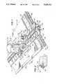
- FIG. 1is a fragmentary perspective view showing a system embodying the present invention
- FIG. 2is a fragmentary sectional view taken along line 2--2 of FIG. 1 and drawn to a scale enlarged therefrom;
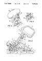
- FIG. 3is an exploded perspective view of a cutter provided hereby
- FIG. 4is a perspective view showing the handle member comprising a component of the cutting head utilized in the cutter of FIGS. 1 and 3;
- FIG. 5is a perspective view showing the cover or clamping piece utilized in cooperation with the handle member of the cutting head;
- FIG. 7is a fragmentary front elevational view of the system of FIG. 1, showing (in full line) the cutting head in its null position, and showing (in phantom line) the head pivoted for operation in both opposite directions from the null position;
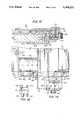
- FIG. 8is a view similar to FIG. 7, in which is utilized a second form of blade and in which a section of the clamping piece is broken away to show underlying features;
- FIG. 9is a sectional view taken along line 9--9 of FIG. 8 and drawn to an enlarged scale;
- FIG. 10is a sectional view taken along line 10--10 of FIG. 7 and drawn to an enlarged scale
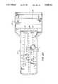
- FIG. 12is a fragmentary elevational view of the section of the system shown in FIG. 11;
- FIG. 14is a view similar to FIG. 11, but showing the workpiece-supporting base inverted side-for-side;
- FIG. 15is an elevational view of the locating block utilized in the system illustrated.
- FIG. 16is a perspective view of a supplemental wedge base constructed for utilization in assembly with the cutter shown in the preceding Figures;
- FIG. 18is a plan view of the cutter assembled with a guide template
- FIG. 19is a fragmentary sectional view taken along line 19--19 of FIG. 18, showing the assembly illustrated therein disposed upon a supported piece of sheet material;
- FIG. 20is a plan view of the template of FIGS. 18 and 19, with the cutter removed;
- FIG. 21is a fragmentary sectional view taken along line 21--21 of FIG. 20, drawn to an enlarged scale;
- FIG. 23is a sectional view taken along line 23--23 of FIG. 1 and drawn to an enlarged scale.
- FIGS. 1 through 10 of the drawingstherein illustrated is a system for cutting sheet material "S", and including a workpiece-supporting base assembly generally designated by the numeral 10, a clamping bar assembly generally designated by the numeral 12, and a cutter including a base and a head assembly, generally designated respectively by the numerals 14 and 16.
- the cutter base 14comprises a hollow elongate body 18, of generally triangular cross section, including opposite end walls 22 and internal walls 24 (only one of each of which is visible), the walls 22, 24 being upwardly indented by a rectangular notch 26 so as to effectively define along the length of the body 18 a downwardly opening channel of effectively uniform, rectangular cross section.
- the lower edges 23 of walls 22, 24decline from adjacent the indentations 26 in both directions toward the opposite outer margins, at which are formed underlying bearing surfaces 28 and 30 extending longitudinally therealong. It will be noted that the lower portion of the body 18 is substantially symmetric to the opposite sides of a vertical plane (in the normal operating position of the cutter) extending through the center of the channel (i.e., it is symmetric in planes to which the axis of the channel is normal), as best seen in FIG. 6.
- the upstanding wall 20 on the base 18has a flat forward contact surface 32, through which extends a central aperture 34; arcuate slots 36, 36' are formed about the aperture 34, and threaded holes 37 extend therethrough for threadably engaging set screws 39.
- the set screwsbear upon tabs (not visible) formed within the base, which in turn bear upon the supporting track for varying the pressure applied thereagainst.
- a pair of threaded apertures 41extend downwardly through the shoulders formed on the body 18, adjacent the opposite ends of the upstanding wall 20, for a purpose that will be discussed more fully below.
- the head assembly 16includes a flat and relatively wide supporting arm 38, which has a bulbous handle portion 40 on its upper end and a V-shaped edge 42, with a beveled marginal portion 44, defining its lower boundary.
- a cylindrical stub 46extends rearwardly from the arm 38, and four threaded holes 48 are formed thereinto in an arcuate array, centered with reference to the stub 46.
- the head assembly 16is pivotably mounted on the base 14 by engagement of the stub 46 in the central aperture 34 of the upstanding wall 20; the parts are secured by three screws 50, which pass through washers 52 and thereafter through the slots 36, 36' and into the threaded holes 48, 48'. It will be appreciated only two of the holes 48 (normally, the outermost ones) will receive screws 50, the others being employed to limit the degree of pivotable movement of the head, if so desired.
- the front face of the supporting arm 38is formed with two upwardly convergent rectilinear channels 54, a laterally extending elongate cavity 56, a slot 58 therebelow, and a shallow trapezoidal recess 60 thereabove.
- the cutter assemblyalso includes a clamping piece, generally designated by the numeral 62.
- the rearward or innermost face of the clamping pieceis, as shown in FIG. 5, formed with upwardly convergent channels 64, and an elongate, laterally extending slot 68; with the clamping piece 62 and arm 38 in assembly, as illustrated, the channels 54, 64 cooperate with one another to define open-ended passages.
- a stud 70having an enlarged, straight-sided oval head, extends through the aligned slots 58, 68 and the aperture 76 of the rectangular blade 74, and engages the knurled nut 72 to secure the blade on the lower end of the handle assembly.
- the upper edge 74' of the bladebears upon the undersides of three teeth 66 to maintain blade position; the teeth 66 project from the clamping piece 62, and seat in the cavity 56 of the arm 38.
- the clamping piece 62has a V-shaped lower edge 77 with a beveled marginal portion 78, thus cooperating with the lower portion of the supporting arm to permit the corner portions 74" of the blade 74 to protrude beyond the lower boundaries of the head assembly for cutting without obstruction; this is best seen in FIG. 7.
- the aligned slots 58, 68permit limited shifting of the blade 74 across the head, and thereby enable ready variation of the depth of cutting.
- FIG. 8shows the cutter used with a second form of blade 82, which is fabricated from an elongate piece of flat metal, sharpened as at 82'(a so-called "Dexter #3" blade).
- the blade 82is secured within one of the passages formed by the cooperating channels 54, 64, and is so positioned that the point of its sharpened edge 82' protrudes slightly beyond the lower boundary of the head.
- the blade 82is brought into operative position by pivoting the handle member in a clockwise direction (as the cutter is depicted in FIG. 8), again causing the point of the blade to penetrate the workpiece in a plunging manner.
- a blade 82would of course be secured in the other passage, in mirror-image relationship.
- FIG. 8(among others) also shows a depth-indicating scale insert 84 affixed within the shallow recess 60, as may be provided by a pressure-sensitive adhesive-coated label; alternatively, appropriate scale markings may be of molded fabrication. Alignment of the curved upper end of the blade 82 with a selected graduation mark will enable a desired depth of cut to be readily replicated.
- the blade 82is secured by the cutting head at a slight angle "a" to the travel path axis.
- the anglewill normally have a value of 1° to 2°, as is known to be desirable from the standpoint of counteracting the tendency that the blade would otherwise have to wander from the intended cut line, and thereby to produce less than ideal precision.
- FIG. 10achieves essentially the same purpose in those instances in which a rectangular blade 74, or another, comparably shaped (e.g., trapezoidal) blade, is employed.
- the outwardly directed face 78 of the arm 38 and the inwardly directed face of the clamping piece 62are concavely and convexly contoured, respectively, to the same, large-radius value. Clamping of the blade 74 between the cooperating components will therefore cause its protruding corner portions 74" to be angled slightly (i.e., typically at 1° to 2° ) with reference to the line of cutting, effective in both direction as well as inversions of the head. Such deformation will also produce a desirable stiffening of the blade 74.
- the cutting head illustratedis designed for use with a workpiece clamping member, such as the assembly 12 hereinabove referred to with reference to FIG. 1. Since that Figure only fragmentarily shows the system, it should be pointed out that the opposite ends of the workpiece-supporting base 10, as well as of the clamping bar assembly 12, will be of substantially identical construction and will have the features hereinafter described with respect to only one end.
- the clamping bar assembly 12consists of an elongate extrusion (normally of aluminum) which is, as best seen in FIG. 6, symmetrical about a longitudinal plane through the center line, the plane being vertical in the position of normal use.
- the extrusionis formed with an elevated track or central portion 86 of generally rectangular cross section, below and from the opposite sides of which extend outwardly tapering shoulder portions 88, terminating in flat marginal portions 90 which provide running surfaces 91 upon which ride the bearing surfaces 28 and 30 of the base 14 when the cutter is assembled therewith.
- the profile of the upper portion of the extrusionconforms in male/female relationship to that of the bottom portion of the cutter base 14, thus permitting slidable seating of the cutter on the clamping bar; the symmetry of the mating parts, about a vertical plane through the channel and track, enables end-for-end inversion of the cutter for ambidextrous use.
- the underlying surfaces of the shoulders 88are flat and coplanar, being thus adapted for holding the sheet material S flat against the top surface of the board 94 of which the workpiece-supporting base assembly 10 is comprised.
- a shallow slot 96extends along the inner margin on the underside of each flange 88, in one of which is shown a rubber element 98 for better restraint of the sheet S against shifting under the clamping bar; elements 98 seated in both slots 96 will generally afford optimal balance.
- Formed into the top surface of the elevated portion 86 of the baris a shallow recess 100, in which is received a scale-bearing insert 102; as seen in FIG. 1, the insert 102 includes both metric and English system linear distance scales.
- the elevated portion 86also provides rectilinear lateral surfaces 104 along its entire length, below which extend undercut grooves 222.
- FIGS. 11 through 15show features of the clamping bar assembly in greater detail.
- an engagement subassemblyis provided at both of the opposite ends of the bar (only one of which is illustrated), which consists of a gripping block, generally designated by the numeral 106, and a cap piece 108 secured in assembly therewith by two nut and bolt fasteners 110.
- the gripping block 106consists of a body portion 112 and a tab portion 114, the latter having a chamfered lower longitudinal edge 145 and being flexibly joined to the body portion by a relatively thin connecting element 116.
- a row of five detent elements or pointed teeth 118extend at equidistantly spaced locations along the inner face of the tab 114 in a normally vertical orientation, perpendicular to the axis of flexure; the detents 118 are spaced with a center-to-center distance of 0.314 inch (7.98 millimeters).
- An adjusting screw 120passes laterally through the body portion 112, and has its threaded inner end portion engaged in a square nut 122 which is trapped against rotation between elements of the gripping block. The tip of the screw 120 bears against the outer face of the tab 114 for application of a variable level of force thereto, and to eliminate excess clearance.
- Both opposite end margins of the base board 94are covered by elongate, U-shaped racks or channel pieces, generally designed by the numeral 124. They are held in place by screws 126 that extend through slots 128 in the central web portion 130 of the channel piece 124, which are longitudinally elongated to afford lateral adjustment.
- Parallel arrays of numerous pointed teeth 132, 134extend lengthwise on the channel piece 124 along the opposite margins of the web portion 130, the individual teeth being oriented perpendicularly to the longitudinal axis; in the array 132, the teeth are graduated in metric increments, with a pitch of 2 millimeters, whereas they are graduated in English system increments in the array 134, with a pitch of 0.0625 inch (1.59 millimeters).
- Flanges 136, 138extend inwardly from the web portion 130 over the opposite faces of the board 94. They carry on their external surfaces distance scales 137, 139, corresponding to the associated arrays of teeth 132, 134 in respect of the system of linear distance measurement indicated. Lines of equidistantly spaced holes 142, 143 extend along the flange portions 136, 138, and are once again located to correspond to the increments on the adjacently disposed (and functionally associated) scales, 137 and 139, respectively.
- FIG. 15best illustrates the locating block that is employed, in conjunction with the edge channel pieces 124 on the ends of the base 94, to facilitate positioning of the clamping bar assembly.
- the blockconsists of a generally rectangular body 144, having a flat forward face 152 on one side.
- Semi-circular pins 146extend in opposite directions from the ends of the body, with their diametric, flat surfaces contiguous with the face 152.
- a circular pin 148extends in the same direction and in alignment behind the semi-circular pin 146 on one end of the block, and a like, circular pin 150 extends similarly from the opposite end; the pin 148 is spaced further from its associated semi-circular pin 146 than is the pin 150. It will be appreciated that these spacings correspond to the spacings between the metric system/English system holes 142, 143 in the opposite sides of the channel piece 124, and enable the locating block to be engaged alternatively therewith.
- the chamfer 145, and the bevel edges 140 extending along the arrays of teethcooperate to facilitate such engagement.
- the detents 118 on the tab 114are spaced so as to permit meshing irrespective of whether the metric or the English system array, 132 or 134, is involved, and that the level of gripping force can readily be adjusted by tightening or loosening of the screw 120.
- springs or other meanscan be provided and so located as to exert a constant upward bias upon the clamping bar assembly, thereby facilitating its release from the supporting base when downward force is relieved.
- An L-shaped extrusion 154is attached as a mat guide to the front edge of the board 94 by screws 156 received in vertical slots 158. This arrangement permits shifting of the extrusion 154 across the thickness of the board 94, to lower the abutment edge presented and thereby facilitate extension of the sheet material S thereover, for convenient downsizing.
- the unitcomprises a supplemental wedge base, generally designated by the numeral 160, which is of hollow construction and consists of a back wall 162, a front wall 164, and opposite end walls 166 (only one of which is shown).
- the front wall 164terminates at its lower edge in a pair of forwardly projecting feet 168, which define an indentation 170 to accommodate lower portions of the cutting head; the front of the feet provide bearing surfaces 169 for using the cutter by running it along any straight edge, as do the surfaces 29 on the cutter itself.
- the wedge unithas a bottom profile that is substantially the same as that of base 14 of the cutter; common numbers are therefore employed to designate the indentation, the bearing surfaces, and the declining edges that extend therebetween, differentiated by the addition of prime marks.
- the supplemental base unit 160is adapted to slidably seat the track portion 86 and engage the clamping bar assembly in the manner hereinabove described with respect to the cutter itself.
- the elevated portion 172has an upstanding boss 176 formed centrally thereon, which is adapted to seat between the internal walls 24 of the cutter base 14; although not illustrated, it will be understood that the spacing between the internal walls 24 is substantially the same as the longitudinal dimension of the boss 176, so as to produce engagement therebetween against lengthwise displacement.
- Threaded holes 178are provided in the shoulders of the elevated portion 172, to the opposite ends of the boss 176, and are so spaced as to align with the threaded apertures 41 of the cutter base 14 when it is mounted upon the supplemental base unit 160, thereby enabling the receipt of fasteners 180 for securely affixing the parts in assembly with one another.
- FIGS. 18 through 22show a template, or guide piece, which is suitable for use alone, for marking borders, as well as for cutting circles in combination with the cutter described.
- the templatehas head and tail portions, generally designated respectively by the numerals 182 and 184.
- the head portion 182is formed with elevated structure 186 profiled to mate with the bottom portion of the cutter base 14, and has a pair of threaded apertures 188 for engagement of the fasteners 180; it is thus adapted to mount the cutter, with or without the supplemental unit 160, and an elongate slot 190 is formed adjacent the tail portion 184 to permit passage of the blade.
- a low ledge 192extends along the slot 190 at the innermost end of the tail portion 184, and projects in the same direction as the structure 186; two divergent lines of equidistantly spaced numbered holes 194 proceed therefrom.
- the corresponding numerical valuewill represent a radial distance.
- the tip 198 of the pivot piece 200is simply inserted through one of the holes 194 to penetrate the surface of the workpiece S (normally into an underlayment), providing a fixed point about which the cutter can pivot for circumscribing a circle.
- the lines of holes 194are angled to increase (typically to 4.5°) the 1° to 2° canting of the blades, as is desirable for making precise curved cuts.
- FIG. 23therein illustrated in detail is a measuring stop device, generally designated by the numeral 204, suitable for use with the clamping bar assembly depicted. As can be seen, it is engaged upon the elevated, ruled portion 86 of the clamping bar and serves of course to restrict travel of the cutting head within measured distances therealong.
- the stop deviceconsists of a body 206 formed with a downwardly opening endwise channel 208, which is dimensioned and configured to slidably seat the device 204 upon the elevated portion 86 of the clamping bar.
- a circular hole 210extends downwardly through the rearward side of the body 206, and a small lip element 212 extends inwardly of the channel 208 along the forward side.
- a locking piecegenerally designated by the numeral 214, has a cylindrical shaft portion 216 rotatably seated in the hole 210, with a knurled head 218 at its upper end and a short cylindrical camming or gripping element 220 at its lower end.
Landscapes
- Life Sciences & Earth Sciences (AREA)
- Forests & Forestry (AREA)
- Engineering & Computer Science (AREA)
- Mechanical Engineering (AREA)
- Details Of Cutting Devices (AREA)
Abstract
Description
Claims (6)
Priority Applications (3)
| Application Number | Priority Date | Filing Date | Title |
|---|---|---|---|
| US07/888,201US5269212A (en) | 1992-05-26 | 1992-05-26 | Mat cutter |
| GB9310275AGB2267245B (en) | 1992-05-26 | 1993-05-19 | Mat cutter |
| US08/146,959US5425295A (en) | 1992-05-26 | 1993-11-03 | Sheet material cutter having pivotable head |
Applications Claiming Priority (1)
| Application Number | Priority Date | Filing Date | Title |
|---|---|---|---|
| US07/888,201US5269212A (en) | 1992-05-26 | 1992-05-26 | Mat cutter |
Related Child Applications (1)
| Application Number | Title | Priority Date | Filing Date |
|---|---|---|---|
| US08/146,959Continuation-In-PartUS5425295A (en) | 1992-05-26 | 1993-11-03 | Sheet material cutter having pivotable head |
Publications (1)
| Publication Number | Publication Date |
|---|---|
| US5269212Atrue US5269212A (en) | 1993-12-14 |
Family
ID=25392731
Family Applications (1)
| Application Number | Title | Priority Date | Filing Date |
|---|---|---|---|
| US07/888,201Expired - Fee RelatedUS5269212A (en) | 1992-05-26 | 1992-05-26 | Mat cutter |
Country Status (2)
| Country | Link |
|---|---|
| US (1) | US5269212A (en) |
| GB (1) | GB2267245B (en) |
Cited By (50)
| Publication number | Priority date | Publication date | Assignee | Title |
|---|---|---|---|---|
| US5425295A (en)* | 1992-05-26 | 1995-06-20 | The Fletcher-Terry Company | Sheet material cutter having pivotable head |
| US5537904A (en)* | 1994-08-11 | 1996-07-23 | Albin; Stephen D. | Reversible mat cutter |
| US6138546A (en)* | 1999-01-14 | 2000-10-31 | John Knoell & Sons, Inc. | Hand-operated cutter for a sheet-like workpiece and a method of cutting |
| US20030051589A1 (en)* | 2001-09-18 | 2003-03-20 | Caputo Mary L. | Apparatus for cutting baked goods and method of use |
| US20030176183A1 (en)* | 2001-04-02 | 2003-09-18 | Therasense, Inc. | Blood glucose tracking apparatus and methods |
| US20030177881A1 (en)* | 2002-03-25 | 2003-09-25 | Long Donald Blaine | Knife attachment for a sheet cutting system |
| GB2413981A (en)* | 2004-05-14 | 2005-11-16 | Primax Electronics Ltd | Flat media cutting device |
| US20070169602A1 (en)* | 2005-11-08 | 2007-07-26 | Peterson Michael E | Device for scoring or cutting sheet material |
| US20070277663A1 (en)* | 2006-05-11 | 2007-12-06 | Fiskars Brands, Inc. | Paper trimmer assembly |
| USD593598S1 (en) | 2005-11-08 | 2009-06-02 | Acme United Corporation | Paper trimmer and scorer |
| US20090178529A1 (en)* | 2008-01-15 | 2009-07-16 | The Fletcher-Terry Company | Apparatus for cutting sheet material |
| US20090188366A1 (en)* | 2008-01-24 | 2009-07-30 | Henry Habra | Gift Wrap Paper Cutter |
| US7587287B2 (en) | 2003-04-04 | 2009-09-08 | Abbott Diabetes Care Inc. | Method and system for transferring analyte test data |
| US20090271993A1 (en)* | 2008-04-30 | 2009-11-05 | Semprini David M | Drywall cutting apparatus |
| US7620438B2 (en) | 2006-03-31 | 2009-11-17 | Abbott Diabetes Care Inc. | Method and system for powering an electronic device |
| US7766829B2 (en) | 2005-11-04 | 2010-08-03 | Abbott Diabetes Care Inc. | Method and system for providing basal profile modification in analyte monitoring and management systems |
| USD624791S1 (en) | 2010-03-16 | 2010-10-05 | Caputo Mary L | Bakery cutting guide |
| US7811231B2 (en) | 2002-12-31 | 2010-10-12 | Abbott Diabetes Care Inc. | Continuous glucose monitoring system and methods of use |
| US7860544B2 (en) | 1998-04-30 | 2010-12-28 | Abbott Diabetes Care Inc. | Analyte monitoring device and methods of use |
| US7920907B2 (en) | 2006-06-07 | 2011-04-05 | Abbott Diabetes Care Inc. | Analyte monitoring system and method |
| US7928850B2 (en) | 2007-05-08 | 2011-04-19 | Abbott Diabetes Care Inc. | Analyte monitoring system and methods |
| US20110226109A1 (en)* | 2010-03-16 | 2011-09-22 | Caputo Mary L | Bakery cutting guide |
| US8066639B2 (en) | 2003-06-10 | 2011-11-29 | Abbott Diabetes Care Inc. | Glucose measuring device for use in personal area network |
| US8103456B2 (en) | 2009-01-29 | 2012-01-24 | Abbott Diabetes Care Inc. | Method and device for early signal attenuation detection using blood glucose measurements |
| US8112240B2 (en) | 2005-04-29 | 2012-02-07 | Abbott Diabetes Care Inc. | Method and apparatus for providing leak detection in data monitoring and management systems |
| US8123686B2 (en) | 2007-03-01 | 2012-02-28 | Abbott Diabetes Care Inc. | Method and apparatus for providing rolling data in communication systems |
| US8149117B2 (en) | 2007-05-08 | 2012-04-03 | Abbott Diabetes Care Inc. | Analyte monitoring system and methods |
| US8226891B2 (en) | 2006-03-31 | 2012-07-24 | Abbott Diabetes Care Inc. | Analyte monitoring devices and methods therefor |
| US8287454B2 (en) | 1998-04-30 | 2012-10-16 | Abbott Diabetes Care Inc. | Analyte monitoring device and methods of use |
| US8346337B2 (en) | 1998-04-30 | 2013-01-01 | Abbott Diabetes Care Inc. | Analyte monitoring device and methods of use |
| US8456301B2 (en) | 2007-05-08 | 2013-06-04 | Abbott Diabetes Care Inc. | Analyte monitoring system and methods |
| US8465425B2 (en) | 1998-04-30 | 2013-06-18 | Abbott Diabetes Care Inc. | Analyte monitoring device and methods of use |
| US8612159B2 (en) | 1998-04-30 | 2013-12-17 | Abbott Diabetes Care Inc. | Analyte monitoring device and methods of use |
| US8652043B2 (en) | 2001-01-02 | 2014-02-18 | Abbott Diabetes Care Inc. | Analyte monitoring device and methods of use |
| US8665091B2 (en) | 2007-05-08 | 2014-03-04 | Abbott Diabetes Care Inc. | Method and device for determining elapsed sensor life |
| US8688188B2 (en) | 1998-04-30 | 2014-04-01 | Abbott Diabetes Care Inc. | Analyte monitoring device and methods of use |
| US8732188B2 (en) | 2007-02-18 | 2014-05-20 | Abbott Diabetes Care Inc. | Method and system for providing contextual based medication dosage determination |
| US8771183B2 (en) | 2004-02-17 | 2014-07-08 | Abbott Diabetes Care Inc. | Method and system for providing data communication in continuous glucose monitoring and management system |
| US8930203B2 (en) | 2007-02-18 | 2015-01-06 | Abbott Diabetes Care Inc. | Multi-function analyte test device and methods therefor |
| US8974386B2 (en) | 1998-04-30 | 2015-03-10 | Abbott Diabetes Care Inc. | Analyte monitoring device and methods of use |
| US8993331B2 (en) | 2009-08-31 | 2015-03-31 | Abbott Diabetes Care Inc. | Analyte monitoring system and methods for managing power and noise |
| US9066695B2 (en) | 1998-04-30 | 2015-06-30 | Abbott Diabetes Care Inc. | Analyte monitoring device and methods of use |
| US9226701B2 (en) | 2009-04-28 | 2016-01-05 | Abbott Diabetes Care Inc. | Error detection in critical repeating data in a wireless sensor system |
| US9314195B2 (en) | 2009-08-31 | 2016-04-19 | Abbott Diabetes Care Inc. | Analyte signal processing device and methods |
| US9320461B2 (en) | 2009-09-29 | 2016-04-26 | Abbott Diabetes Care Inc. | Method and apparatus for providing notification function in analyte monitoring systems |
| US20180043573A1 (en)* | 2015-03-20 | 2018-02-15 | Germans Boada, S.A. | Set square for manual ceramic cutter |
| US9968306B2 (en) | 2012-09-17 | 2018-05-15 | Abbott Diabetes Care Inc. | Methods and apparatuses for providing adverse condition notification with enhanced wireless communication range in analyte monitoring systems |
| US9980669B2 (en) | 2011-11-07 | 2018-05-29 | Abbott Diabetes Care Inc. | Analyte monitoring device and methods |
| US11590670B2 (en)* | 2019-05-31 | 2023-02-28 | The Boeing Company | Methods and apparatus to align applique cutters |
| US11793936B2 (en) | 2009-05-29 | 2023-10-24 | Abbott Diabetes Care Inc. | Medical device antenna systems having external antenna configurations |
Families Citing this family (1)
| Publication number | Priority date | Publication date | Assignee | Title |
|---|---|---|---|---|
| GB2321209B (en)* | 1997-01-17 | 2000-01-12 | Kenncut Ltd | Machines for cutting card, board and like material |
Citations (18)
| Publication number | Priority date | Publication date | Assignee | Title |
|---|---|---|---|---|
| US1250538A (en)* | 1916-03-29 | 1917-12-18 | Ridgely Trimmer Company | Cutting-tool. |
| US1996224A (en)* | 1933-01-11 | 1935-04-02 | Wedekind August | Paper cutter |
| US2633196A (en)* | 1950-05-09 | 1953-03-31 | Taran Harry | Straightedge and paper cutter |
| US2924010A (en)* | 1960-02-09 | Cutting instrument with angularly | ||
| US3108349A (en)* | 1960-06-23 | 1963-10-29 | Vitramon Inc | Apparatus for cutting sheets of soft semi-plastic material |
| US3213736A (en)* | 1963-10-16 | 1965-10-26 | William B Keeton | Cutter for picture frame mats |
| US3964360A (en)* | 1975-12-22 | 1976-06-22 | Joseph Schwartz | Sheet material cutting apparatus |
| US3996827A (en)* | 1975-08-25 | 1976-12-14 | Malcolm Logan | Cutter for mats |
| US4064626A (en)* | 1976-09-09 | 1977-12-27 | Cbs Inc. | Cutter for sheet material |
| US4262419A (en)* | 1979-03-21 | 1981-04-21 | Pierce Donald C | Hand-held cutter for cutting mounting board and the like |
| US4413452A (en)* | 1979-10-17 | 1983-11-08 | Wilkinson Don G | Building structure |
| US4506576A (en)* | 1983-07-07 | 1985-03-26 | Minnesota Mining And Manufacturing Company | Mat board cutter with knife blade securing safety pin |
| US4590834A (en)* | 1984-09-28 | 1986-05-27 | Sobel David D | Apparatus for simultaneously cutting a plurality of picture frame mats |
| US4685366A (en)* | 1985-08-07 | 1987-08-11 | Beder Samuel L | Holdfast cutting system |
| US4798112A (en)* | 1987-02-11 | 1989-01-17 | The Fletcher-Terry Company | Head assembly for mat cutting machine |
| US4858507A (en)* | 1983-04-20 | 1989-08-22 | Esselte Pendaflex Corporation | Mat board cutter with adjustable cutter-carrying body |
| US4941380A (en)* | 1988-03-17 | 1990-07-17 | Keencut Limited | Machines for cutting cardboards and like materials |
| US4986156A (en)* | 1990-04-13 | 1991-01-22 | Mcginnis Michael J | Mat cutting device |
Family Cites Families (1)
| Publication number | Priority date | Publication date | Assignee | Title |
|---|---|---|---|---|
| GB2249516B (en)* | 1990-11-10 | 1994-05-25 | Michael Charles Young | Improvements relating to a mount cutter |
- 1992
- 1992-05-26USUS07/888,201patent/US5269212A/ennot_activeExpired - Fee Related
- 1993
- 1993-05-19GBGB9310275Apatent/GB2267245B/ennot_activeExpired - Fee Related
Patent Citations (18)
| Publication number | Priority date | Publication date | Assignee | Title |
|---|---|---|---|---|
| US2924010A (en)* | 1960-02-09 | Cutting instrument with angularly | ||
| US1250538A (en)* | 1916-03-29 | 1917-12-18 | Ridgely Trimmer Company | Cutting-tool. |
| US1996224A (en)* | 1933-01-11 | 1935-04-02 | Wedekind August | Paper cutter |
| US2633196A (en)* | 1950-05-09 | 1953-03-31 | Taran Harry | Straightedge and paper cutter |
| US3108349A (en)* | 1960-06-23 | 1963-10-29 | Vitramon Inc | Apparatus for cutting sheets of soft semi-plastic material |
| US3213736A (en)* | 1963-10-16 | 1965-10-26 | William B Keeton | Cutter for picture frame mats |
| US3996827A (en)* | 1975-08-25 | 1976-12-14 | Malcolm Logan | Cutter for mats |
| US3964360A (en)* | 1975-12-22 | 1976-06-22 | Joseph Schwartz | Sheet material cutting apparatus |
| US4064626A (en)* | 1976-09-09 | 1977-12-27 | Cbs Inc. | Cutter for sheet material |
| US4262419A (en)* | 1979-03-21 | 1981-04-21 | Pierce Donald C | Hand-held cutter for cutting mounting board and the like |
| US4413452A (en)* | 1979-10-17 | 1983-11-08 | Wilkinson Don G | Building structure |
| US4858507A (en)* | 1983-04-20 | 1989-08-22 | Esselte Pendaflex Corporation | Mat board cutter with adjustable cutter-carrying body |
| US4506576A (en)* | 1983-07-07 | 1985-03-26 | Minnesota Mining And Manufacturing Company | Mat board cutter with knife blade securing safety pin |
| US4590834A (en)* | 1984-09-28 | 1986-05-27 | Sobel David D | Apparatus for simultaneously cutting a plurality of picture frame mats |
| US4685366A (en)* | 1985-08-07 | 1987-08-11 | Beder Samuel L | Holdfast cutting system |
| US4798112A (en)* | 1987-02-11 | 1989-01-17 | The Fletcher-Terry Company | Head assembly for mat cutting machine |
| US4941380A (en)* | 1988-03-17 | 1990-07-17 | Keencut Limited | Machines for cutting cardboards and like materials |
| US4986156A (en)* | 1990-04-13 | 1991-01-22 | Mcginnis Michael J | Mat cutting device |
Non-Patent Citations (3)
| Title |
|---|
| Brochure Illustration "ALTO Model 45 Mat Cutter" (United Manufacturer's Supplies). |
| Brochure Illustration ALTO Model 45 Mat Cutter (United Manufacturer s Supplies).* |
| Brookstone Catalogue, p. 55.* |
Cited By (186)
| Publication number | Priority date | Publication date | Assignee | Title |
|---|---|---|---|---|
| US5425295A (en)* | 1992-05-26 | 1995-06-20 | The Fletcher-Terry Company | Sheet material cutter having pivotable head |
| US5537904A (en)* | 1994-08-11 | 1996-07-23 | Albin; Stephen D. | Reversible mat cutter |
| US8672844B2 (en) | 1998-04-30 | 2014-03-18 | Abbott Diabetes Care Inc. | Analyte monitoring device and methods of use |
| US8666469B2 (en) | 1998-04-30 | 2014-03-04 | Abbott Diabetes Care Inc. | Analyte monitoring device and methods of use |
| US9011331B2 (en) | 1998-04-30 | 2015-04-21 | Abbott Diabetes Care Inc. | Analyte monitoring device and methods of use |
| US9042953B2 (en) | 1998-04-30 | 2015-05-26 | Abbott Diabetes Care Inc. | Analyte monitoring device and methods of use |
| US8974386B2 (en) | 1998-04-30 | 2015-03-10 | Abbott Diabetes Care Inc. | Analyte monitoring device and methods of use |
| US9066697B2 (en) | 1998-04-30 | 2015-06-30 | Abbott Diabetes Care Inc. | Analyte monitoring device and methods of use |
| US9066695B2 (en) | 1998-04-30 | 2015-06-30 | Abbott Diabetes Care Inc. | Analyte monitoring device and methods of use |
| US8880137B2 (en) | 1998-04-30 | 2014-11-04 | Abbott Diabetes Care Inc. | Analyte monitoring device and methods of use |
| US8840553B2 (en) | 1998-04-30 | 2014-09-23 | Abbott Diabetes Care Inc. | Analyte monitoring device and methods of use |
| US8774887B2 (en) | 1998-04-30 | 2014-07-08 | Abbott Diabetes Care Inc. | Analyte monitoring device and methods of use |
| US8744545B2 (en) | 1998-04-30 | 2014-06-03 | Abbott Diabetes Care Inc. | Analyte monitoring device and methods of use |
| US8738109B2 (en) | 1998-04-30 | 2014-05-27 | Abbott Diabetes Care Inc. | Analyte monitoring device and methods of use |
| US8734348B2 (en) | 1998-04-30 | 2014-05-27 | Abbott Diabetes Care Inc. | Analyte monitoring device and methods of use |
| US8734346B2 (en) | 1998-04-30 | 2014-05-27 | Abbott Diabetes Care Inc. | Analyte monitoring device and methods of use |
| US9072477B2 (en) | 1998-04-30 | 2015-07-07 | Abbott Diabetes Care Inc. | Analyte monitoring device and methods of use |
| US8688188B2 (en) | 1998-04-30 | 2014-04-01 | Abbott Diabetes Care Inc. | Analyte monitoring device and methods of use |
| US9066694B2 (en) | 1998-04-30 | 2015-06-30 | Abbott Diabetes Care Inc. | Analyte monitoring device and methods of use |
| US8670815B2 (en) | 1998-04-30 | 2014-03-11 | Abbott Diabetes Care Inc. | Analyte monitoring device and methods of use |
| US9014773B2 (en) | 1998-04-30 | 2015-04-21 | Abbott Diabetes Care Inc. | Analyte monitoring device and methods of use |
| US8660627B2 (en) | 1998-04-30 | 2014-02-25 | Abbott Diabetes Care Inc. | Analyte monitoring device and methods of use |
| US7860544B2 (en) | 1998-04-30 | 2010-12-28 | Abbott Diabetes Care Inc. | Analyte monitoring device and methods of use |
| US7869853B1 (en) | 1998-04-30 | 2011-01-11 | Abbott Diabetes Care Inc. | Analyte monitoring device and methods of use |
| US7885699B2 (en) | 1998-04-30 | 2011-02-08 | Abbott Diabetes Care Inc. | Analyte monitoring device and methods of use |
| US8649841B2 (en) | 1998-04-30 | 2014-02-11 | Abbott Diabetes Care Inc. | Analyte monitoring device and methods of use |
| US10478108B2 (en) | 1998-04-30 | 2019-11-19 | Abbott Diabetes Care Inc. | Analyte monitoring device and methods of use |
| US8641619B2 (en) | 1998-04-30 | 2014-02-04 | Abbott Diabetes Care Inc. | Analyte monitoring device and methods of use |
| US8622906B2 (en) | 1998-04-30 | 2014-01-07 | Abbott Diabetes Care Inc. | Analyte monitoring device and methods of use |
| US8617071B2 (en) | 1998-04-30 | 2013-12-31 | Abbott Diabetes Care Inc. | Analyte monitoring device and methods of use |
| US8612159B2 (en) | 1998-04-30 | 2013-12-17 | Abbott Diabetes Care Inc. | Analyte monitoring device and methods of use |
| US9326714B2 (en) | 1998-04-30 | 2016-05-03 | Abbott Diabetes Care Inc. | Analyte monitoring device and methods of use |
| US8597189B2 (en) | 1998-04-30 | 2013-12-03 | Abbott Diabetes Care Inc. | Analyte monitoring device and methods of use |
| US8480580B2 (en) | 1998-04-30 | 2013-07-09 | Abbott Diabetes Care Inc. | Analyte monitoring device and methods of use |
| US8162829B2 (en) | 1998-04-30 | 2012-04-24 | Abbott Diabetes Care Inc. | Analyte monitoring device and methods of use |
| US8175673B2 (en) | 1998-04-30 | 2012-05-08 | Abbott Diabetes Care Inc. | Analyte monitoring device and methods of use |
| US8177716B2 (en) | 1998-04-30 | 2012-05-15 | Abbott Diabetes Care Inc. | Analyte monitoring device and methods of use |
| US8473021B2 (en) | 1998-04-30 | 2013-06-25 | Abbott Diabetes Care Inc. | Analyte monitoring device and methods of use |
| US8224413B2 (en) | 1998-04-30 | 2012-07-17 | Abbott Diabetes Care Inc. | Analyte monitoring device and methods of use |
| US8226555B2 (en) | 1998-04-30 | 2012-07-24 | Abbott Diabetes Care Inc. | Analyte monitoring device and methods of use |
| US8226558B2 (en) | 1998-04-30 | 2012-07-24 | Abbott Diabetes Care Inc. | Analyte monitoring device and methods of use |
| US8465425B2 (en) | 1998-04-30 | 2013-06-18 | Abbott Diabetes Care Inc. | Analyte monitoring device and methods of use |
| US8226557B2 (en) | 1998-04-30 | 2012-07-24 | Abbott Diabetes Care Inc. | Analyte monitoring device and methods of use |
| US8231532B2 (en) | 1998-04-30 | 2012-07-31 | Abbott Diabetes Care Inc. | Analyte monitoring device and methods of use |
| US8409131B2 (en) | 1998-04-30 | 2013-04-02 | Abbott Diabetes Care Inc. | Analyte monitoring device and methods of use |
| US8235896B2 (en) | 1998-04-30 | 2012-08-07 | Abbott Diabetes Care Inc. | Analyte monitoring device and methods of use |
| US8255031B2 (en) | 1998-04-30 | 2012-08-28 | Abbott Diabetes Care Inc. | Analyte monitoring device and methods of use |
| US8260392B2 (en) | 1998-04-30 | 2012-09-04 | Abbott Diabetes Care Inc. | Analyte monitoring device and methods of use |
| US8265726B2 (en) | 1998-04-30 | 2012-09-11 | Abbott Diabetes Care Inc. | Analyte monitoring device and methods of use |
| US8391945B2 (en) | 1998-04-30 | 2013-03-05 | Abbott Diabetes Care Inc. | Analyte monitoring device and methods of use |
| US8275439B2 (en) | 1998-04-30 | 2012-09-25 | Abbott Diabetes Care Inc. | Analyte monitoring device and methods of use |
| US8273022B2 (en) | 1998-04-30 | 2012-09-25 | Abbott Diabetes Care Inc. | Analyte monitoring device and methods of use |
| US8287454B2 (en) | 1998-04-30 | 2012-10-16 | Abbott Diabetes Care Inc. | Analyte monitoring device and methods of use |
| US8306598B2 (en) | 1998-04-30 | 2012-11-06 | Abbott Diabetes Care Inc. | Analyte monitoring device and methods of use |
| US8346337B2 (en) | 1998-04-30 | 2013-01-01 | Abbott Diabetes Care Inc. | Analyte monitoring device and methods of use |
| US8346336B2 (en) | 1998-04-30 | 2013-01-01 | Abbott Diabetes Care Inc. | Analyte monitoring device and methods of use |
| US8353829B2 (en) | 1998-04-30 | 2013-01-15 | Abbott Diabetes Care Inc. | Analyte monitoring device and methods of use |
| US8357091B2 (en) | 1998-04-30 | 2013-01-22 | Abbott Diabetes Care Inc. | Analyte monitoring device and methods of use |
| US8380273B2 (en) | 1998-04-30 | 2013-02-19 | Abbott Diabetes Care Inc. | Analyte monitoring device and methods of use |
| US8366614B2 (en) | 1998-04-30 | 2013-02-05 | Abbott Diabetes Care Inc. | Analyte monitoring device and methods of use |
| US8372005B2 (en) | 1998-04-30 | 2013-02-12 | Abbott Diabetes Care Inc. | Analyte monitoring device and methods of use |
| US6138546A (en)* | 1999-01-14 | 2000-10-31 | John Knoell & Sons, Inc. | Hand-operated cutter for a sheet-like workpiece and a method of cutting |
| US9498159B2 (en) | 2001-01-02 | 2016-11-22 | Abbott Diabetes Care Inc. | Analyte monitoring device and methods of use |
| US8652043B2 (en) | 2001-01-02 | 2014-02-18 | Abbott Diabetes Care Inc. | Analyte monitoring device and methods of use |
| US8668645B2 (en) | 2001-01-02 | 2014-03-11 | Abbott Diabetes Care Inc. | Analyte monitoring device and methods of use |
| US9011332B2 (en) | 2001-01-02 | 2015-04-21 | Abbott Diabetes Care Inc. | Analyte monitoring device and methods of use |
| US9610034B2 (en) | 2001-01-02 | 2017-04-04 | Abbott Diabetes Care Inc. | Analyte monitoring device and methods of use |
| US8765059B2 (en) | 2001-04-02 | 2014-07-01 | Abbott Diabetes Care Inc. | Blood glucose tracking apparatus |
| US7976778B2 (en) | 2001-04-02 | 2011-07-12 | Abbott Diabetes Care Inc. | Blood glucose tracking apparatus |
| US20030176183A1 (en)* | 2001-04-02 | 2003-09-18 | Therasense, Inc. | Blood glucose tracking apparatus and methods |
| US8268243B2 (en) | 2001-04-02 | 2012-09-18 | Abbott Diabetes Care Inc. | Blood glucose tracking apparatus and methods |
| US7041468B2 (en) | 2001-04-02 | 2006-05-09 | Therasense, Inc. | Blood glucose tracking apparatus and methods |
| US9477811B2 (en) | 2001-04-02 | 2016-10-25 | Abbott Diabetes Care Inc. | Blood glucose tracking apparatus and methods |
| US8236242B2 (en) | 2001-04-02 | 2012-08-07 | Abbott Diabetes Care Inc. | Blood glucose tracking apparatus and methods |
| US20030051589A1 (en)* | 2001-09-18 | 2003-03-20 | Caputo Mary L. | Apparatus for cutting baked goods and method of use |
| US6745660B2 (en)* | 2001-09-18 | 2004-06-08 | Mary L. Caputo | Apparatus for cutting baked goods and method of use |
| US6729219B2 (en)* | 2002-03-25 | 2004-05-04 | Long Industries, Inc. | Knife attachment for a sheet cutting system |
| US20030177881A1 (en)* | 2002-03-25 | 2003-09-25 | Long Donald Blaine | Knife attachment for a sheet cutting system |
| US10750952B2 (en) | 2002-12-31 | 2020-08-25 | Abbott Diabetes Care Inc. | Continuous glucose monitoring system and methods of use |
| US10039881B2 (en) | 2002-12-31 | 2018-08-07 | Abbott Diabetes Care Inc. | Method and system for providing data communication in continuous glucose monitoring and management system |
| US7811231B2 (en) | 2002-12-31 | 2010-10-12 | Abbott Diabetes Care Inc. | Continuous glucose monitoring system and methods of use |
| US8622903B2 (en) | 2002-12-31 | 2014-01-07 | Abbott Diabetes Care Inc. | Continuous glucose monitoring system and methods of use |
| US9962091B2 (en) | 2002-12-31 | 2018-05-08 | Abbott Diabetes Care Inc. | Continuous glucose monitoring system and methods of use |
| US8187183B2 (en) | 2002-12-31 | 2012-05-29 | Abbott Diabetes Care Inc. | Continuous glucose monitoring system and methods of use |
| US8560250B2 (en) | 2003-04-04 | 2013-10-15 | Abbott Laboratories | Method and system for transferring analyte test data |
| US7587287B2 (en) | 2003-04-04 | 2009-09-08 | Abbott Diabetes Care Inc. | Method and system for transferring analyte test data |
| US8437966B2 (en) | 2003-04-04 | 2013-05-07 | Abbott Diabetes Care Inc. | Method and system for transferring analyte test data |
| US8682598B2 (en) | 2003-04-04 | 2014-03-25 | Abbott Laboratories | Method and system for transferring analyte test data |
| US8483974B2 (en) | 2003-04-04 | 2013-07-09 | Abbott Diabetes Care Inc. | Method and system for transferring analyte test data |
| US8066639B2 (en) | 2003-06-10 | 2011-11-29 | Abbott Diabetes Care Inc. | Glucose measuring device for use in personal area network |
| US8512239B2 (en) | 2003-06-10 | 2013-08-20 | Abbott Diabetes Care Inc. | Glucose measuring device for use in personal area network |
| US9730584B2 (en) | 2003-06-10 | 2017-08-15 | Abbott Diabetes Care Inc. | Glucose measuring device for use in personal area network |
| US8647269B2 (en) | 2003-06-10 | 2014-02-11 | Abbott Diabetes Care Inc. | Glucose measuring device for use in personal area network |
| US8771183B2 (en) | 2004-02-17 | 2014-07-08 | Abbott Diabetes Care Inc. | Method and system for providing data communication in continuous glucose monitoring and management system |
| GB2413981A (en)* | 2004-05-14 | 2005-11-16 | Primax Electronics Ltd | Flat media cutting device |
| US8112240B2 (en) | 2005-04-29 | 2012-02-07 | Abbott Diabetes Care Inc. | Method and apparatus for providing leak detection in data monitoring and management systems |
| US8915850B2 (en) | 2005-11-01 | 2014-12-23 | Abbott Diabetes Care Inc. | Analyte monitoring device and methods of use |
| US11103165B2 (en) | 2005-11-01 | 2021-08-31 | Abbott Diabetes Care Inc. | Analyte monitoring device and methods of use |
| US11399748B2 (en) | 2005-11-01 | 2022-08-02 | Abbott Diabetes Care Inc. | Analyte monitoring device and methods of use |
| US10231654B2 (en) | 2005-11-01 | 2019-03-19 | Abbott Diabetes Care Inc. | Analyte monitoring device and methods of use |
| US10952652B2 (en) | 2005-11-01 | 2021-03-23 | Abbott Diabetes Care Inc. | Analyte monitoring device and methods of use |
| US9326716B2 (en) | 2005-11-01 | 2016-05-03 | Abbott Diabetes Care Inc. | Analyte monitoring device and methods of use |
| US11272867B2 (en) | 2005-11-01 | 2022-03-15 | Abbott Diabetes Care Inc. | Analyte monitoring device and methods of use |
| US11911151B1 (en) | 2005-11-01 | 2024-02-27 | Abbott Diabetes Care Inc. | Analyte monitoring device and methods of use |
| US10201301B2 (en) | 2005-11-01 | 2019-02-12 | Abbott Diabetes Care Inc. | Analyte monitoring device and methods of use |
| US11363975B2 (en) | 2005-11-01 | 2022-06-21 | Abbott Diabetes Care Inc. | Analyte monitoring device and methods of use |
| US9078607B2 (en) | 2005-11-01 | 2015-07-14 | Abbott Diabetes Care Inc. | Analyte monitoring device and methods of use |
| US8920319B2 (en) | 2005-11-01 | 2014-12-30 | Abbott Diabetes Care Inc. | Analyte monitoring device and methods of use |
| US8585591B2 (en) | 2005-11-04 | 2013-11-19 | Abbott Diabetes Care Inc. | Method and system for providing basal profile modification in analyte monitoring and management systems |
| US7766829B2 (en) | 2005-11-04 | 2010-08-03 | Abbott Diabetes Care Inc. | Method and system for providing basal profile modification in analyte monitoring and management systems |
| US9323898B2 (en) | 2005-11-04 | 2016-04-26 | Abbott Diabetes Care Inc. | Method and system for providing basal profile modification in analyte monitoring and management systems |
| US9669162B2 (en) | 2005-11-04 | 2017-06-06 | Abbott Diabetes Care Inc. | Method and system for providing basal profile modification in analyte monitoring and management systems |
| US11538580B2 (en) | 2005-11-04 | 2022-12-27 | Abbott Diabetes Care Inc. | Method and system for providing basal profile modification in analyte monitoring and management systems |
| US20070169602A1 (en)* | 2005-11-08 | 2007-07-26 | Peterson Michael E | Device for scoring or cutting sheet material |
| USD593598S1 (en) | 2005-11-08 | 2009-06-02 | Acme United Corporation | Paper trimmer and scorer |
| US8226891B2 (en) | 2006-03-31 | 2012-07-24 | Abbott Diabetes Care Inc. | Analyte monitoring devices and methods therefor |
| US9625413B2 (en) | 2006-03-31 | 2017-04-18 | Abbott Diabetes Care Inc. | Analyte monitoring devices and methods therefor |
| US8593109B2 (en) | 2006-03-31 | 2013-11-26 | Abbott Diabetes Care Inc. | Method and system for powering an electronic device |
| US9039975B2 (en) | 2006-03-31 | 2015-05-26 | Abbott Diabetes Care Inc. | Analyte monitoring devices and methods therefor |
| US8933664B2 (en) | 2006-03-31 | 2015-01-13 | Abbott Diabetes Care Inc. | Method and system for powering an electronic device |
| US9380971B2 (en) | 2006-03-31 | 2016-07-05 | Abbott Diabetes Care Inc. | Method and system for powering an electronic device |
| US9743863B2 (en) | 2006-03-31 | 2017-08-29 | Abbott Diabetes Care Inc. | Method and system for powering an electronic device |
| US8597575B2 (en) | 2006-03-31 | 2013-12-03 | Abbott Diabetes Care Inc. | Analyte monitoring devices and methods therefor |
| US7620438B2 (en) | 2006-03-31 | 2009-11-17 | Abbott Diabetes Care Inc. | Method and system for powering an electronic device |
| US20070277663A1 (en)* | 2006-05-11 | 2007-12-06 | Fiskars Brands, Inc. | Paper trimmer assembly |
| US7920907B2 (en) | 2006-06-07 | 2011-04-05 | Abbott Diabetes Care Inc. | Analyte monitoring system and method |
| US12040067B2 (en) | 2007-02-18 | 2024-07-16 | Abbott Diabetes Care Inc. | Method and system for providing contextual based medication dosage determination |
| US8732188B2 (en) | 2007-02-18 | 2014-05-20 | Abbott Diabetes Care Inc. | Method and system for providing contextual based medication dosage determination |
| US8930203B2 (en) | 2007-02-18 | 2015-01-06 | Abbott Diabetes Care Inc. | Multi-function analyte test device and methods therefor |
| US9095290B2 (en) | 2007-03-01 | 2015-08-04 | Abbott Diabetes Care Inc. | Method and apparatus for providing rolling data in communication systems |
| US8123686B2 (en) | 2007-03-01 | 2012-02-28 | Abbott Diabetes Care Inc. | Method and apparatus for providing rolling data in communication systems |
| US9801545B2 (en) | 2007-03-01 | 2017-10-31 | Abbott Diabetes Care Inc. | Method and apparatus for providing rolling data in communication systems |
| US12357180B2 (en) | 2007-05-08 | 2025-07-15 | Abbott Diabetes Care Inc. | Analyte monitoring system and methods |
| US8362904B2 (en) | 2007-05-08 | 2013-01-29 | Abbott Diabetes Care Inc. | Analyte monitoring system and methods |
| US9177456B2 (en) | 2007-05-08 | 2015-11-03 | Abbott Diabetes Care Inc. | Analyte monitoring system and methods |
| US8593287B2 (en) | 2007-05-08 | 2013-11-26 | Abbott Diabetes Care Inc. | Analyte monitoring system and methods |
| US9314198B2 (en) | 2007-05-08 | 2016-04-19 | Abbott Diabetes Care Inc. | Analyte monitoring system and methods |
| US9035767B2 (en) | 2007-05-08 | 2015-05-19 | Abbott Diabetes Care Inc. | Analyte monitoring system and methods |
| US9574914B2 (en) | 2007-05-08 | 2017-02-21 | Abbott Diabetes Care Inc. | Method and device for determining elapsed sensor life |
| US8461985B2 (en) | 2007-05-08 | 2013-06-11 | Abbott Diabetes Care Inc. | Analyte monitoring system and methods |
| US8665091B2 (en) | 2007-05-08 | 2014-03-04 | Abbott Diabetes Care Inc. | Method and device for determining elapsed sensor life |
| US9649057B2 (en) | 2007-05-08 | 2017-05-16 | Abbott Diabetes Care Inc. | Analyte monitoring system and methods |
| US8456301B2 (en) | 2007-05-08 | 2013-06-04 | Abbott Diabetes Care Inc. | Analyte monitoring system and methods |
| US11696684B2 (en) | 2007-05-08 | 2023-07-11 | Abbott Diabetes Care Inc. | Analyte monitoring system and methods |
| US12396645B2 (en) | 2007-05-08 | 2025-08-26 | Abbott Diabetes Care Inc. | Analyte monitoring system and methods |
| US10952611B2 (en) | 2007-05-08 | 2021-03-23 | Abbott Diabetes Care Inc. | Analyte monitoring system and methods |
| US10178954B2 (en) | 2007-05-08 | 2019-01-15 | Abbott Diabetes Care Inc. | Analyte monitoring system and methods |
| US9000929B2 (en) | 2007-05-08 | 2015-04-07 | Abbott Diabetes Care Inc. | Analyte monitoring system and methods |
| US9949678B2 (en) | 2007-05-08 | 2018-04-24 | Abbott Diabetes Care Inc. | Method and device for determining elapsed sensor life |
| US8149117B2 (en) | 2007-05-08 | 2012-04-03 | Abbott Diabetes Care Inc. | Analyte monitoring system and methods |
| US10653317B2 (en) | 2007-05-08 | 2020-05-19 | Abbott Diabetes Care Inc. | Analyte monitoring system and methods |
| US7928850B2 (en) | 2007-05-08 | 2011-04-19 | Abbott Diabetes Care Inc. | Analyte monitoring system and methods |
| US20090178529A1 (en)* | 2008-01-15 | 2009-07-16 | The Fletcher-Terry Company | Apparatus for cutting sheet material |
| US7694617B2 (en)* | 2008-01-24 | 2010-04-13 | Henry Habra | Gift wrap paper cutter |
| US20090188366A1 (en)* | 2008-01-24 | 2009-07-30 | Henry Habra | Gift Wrap Paper Cutter |
| US20090271993A1 (en)* | 2008-04-30 | 2009-11-05 | Semprini David M | Drywall cutting apparatus |
| US8473220B2 (en) | 2009-01-29 | 2013-06-25 | Abbott Diabetes Care Inc. | Method and device for early signal attenuation detection using blood glucose measurements |
| US8103456B2 (en) | 2009-01-29 | 2012-01-24 | Abbott Diabetes Care Inc. | Method and device for early signal attenuation detection using blood glucose measurements |
| US8676513B2 (en) | 2009-01-29 | 2014-03-18 | Abbott Diabetes Care Inc. | Method and device for early signal attenuation detection using blood glucose measurements |
| US9066709B2 (en) | 2009-01-29 | 2015-06-30 | Abbott Diabetes Care Inc. | Method and device for early signal attenuation detection using blood glucose measurements |
| US9226701B2 (en) | 2009-04-28 | 2016-01-05 | Abbott Diabetes Care Inc. | Error detection in critical repeating data in a wireless sensor system |
| US12364815B2 (en) | 2009-05-29 | 2025-07-22 | Abbott Diabetes Care Inc. | Medical device antenna systems having external antenna configurations |
| US11872370B2 (en) | 2009-05-29 | 2024-01-16 | Abbott Diabetes Care Inc. | Medical device antenna systems having external antenna configurations |
| US11793936B2 (en) | 2009-05-29 | 2023-10-24 | Abbott Diabetes Care Inc. | Medical device antenna systems having external antenna configurations |
| US9968302B2 (en) | 2009-08-31 | 2018-05-15 | Abbott Diabetes Care Inc. | Analyte signal processing device and methods |
| US12279894B2 (en) | 2009-08-31 | 2025-04-22 | Abbott Diabetes Care Inc. | Analyte signal processing device and methods |
| US9314195B2 (en) | 2009-08-31 | 2016-04-19 | Abbott Diabetes Care Inc. | Analyte signal processing device and methods |
| US11150145B2 (en) | 2009-08-31 | 2021-10-19 | Abbott Diabetes Care Inc. | Analyte monitoring system and methods for managing power and noise |
| US11045147B2 (en) | 2009-08-31 | 2021-06-29 | Abbott Diabetes Care Inc. | Analyte signal processing device and methods |
| US8993331B2 (en) | 2009-08-31 | 2015-03-31 | Abbott Diabetes Care Inc. | Analyte monitoring system and methods for managing power and noise |
| US10429250B2 (en) | 2009-08-31 | 2019-10-01 | Abbott Diabetes Care, Inc. | Analyte monitoring system and methods for managing power and noise |
| US11635332B2 (en) | 2009-08-31 | 2023-04-25 | Abbott Diabetes Care Inc. | Analyte monitoring system and methods for managing power and noise |
| US9750439B2 (en) | 2009-09-29 | 2017-09-05 | Abbott Diabetes Care Inc. | Method and apparatus for providing notification function in analyte monitoring systems |
| US10349874B2 (en) | 2009-09-29 | 2019-07-16 | Abbott Diabetes Care Inc. | Method and apparatus for providing notification function in analyte monitoring systems |
| US9320461B2 (en) | 2009-09-29 | 2016-04-26 | Abbott Diabetes Care Inc. | Method and apparatus for providing notification function in analyte monitoring systems |
| US9550305B2 (en) | 2010-03-16 | 2017-01-24 | Mary L. Caputo | Bakery cutting guide |
| USD624791S1 (en) | 2010-03-16 | 2010-10-05 | Caputo Mary L | Bakery cutting guide |
| US20110226109A1 (en)* | 2010-03-16 | 2011-09-22 | Caputo Mary L | Bakery cutting guide |
| US9980669B2 (en) | 2011-11-07 | 2018-05-29 | Abbott Diabetes Care Inc. | Analyte monitoring device and methods |
| US11612363B2 (en) | 2012-09-17 | 2023-03-28 | Abbott Diabetes Care Inc. | Methods and apparatuses for providing adverse condition notification with enhanced wireless communication range in analyte monitoring systems |
| US11950936B2 (en) | 2012-09-17 | 2024-04-09 | Abbott Diabetes Care Inc. | Methods and apparatuses for providing adverse condition notification with enhanced wireless communication range in analyte monitoring systems |
| US9968306B2 (en) | 2012-09-17 | 2018-05-15 | Abbott Diabetes Care Inc. | Methods and apparatuses for providing adverse condition notification with enhanced wireless communication range in analyte monitoring systems |
| US12419589B2 (en) | 2012-09-17 | 2025-09-23 | Abbott Diabetes Care Inc. | Methods and apparatuses for providing adverse condition notification with enhanced wireless communication range in analyte monitoring systems |
| US10525612B2 (en)* | 2015-03-20 | 2020-01-07 | Germans Boada, S.A. | Set square for manual ceramic cutter |
| US20180043573A1 (en)* | 2015-03-20 | 2018-02-15 | Germans Boada, S.A. | Set square for manual ceramic cutter |
| US11590670B2 (en)* | 2019-05-31 | 2023-02-28 | The Boeing Company | Methods and apparatus to align applique cutters |
Also Published As
| Publication number | Publication date |
|---|---|
| GB2267245A (en) | 1993-12-01 |
| GB2267245B (en) | 1995-03-08 |
| GB9310275D0 (en) | 1993-06-30 |
Similar Documents
| Publication | Publication Date | Title |
|---|---|---|
| US5269212A (en) | Mat cutter | |
| US5271305A (en) | Base and clamping bar assembly | |
| US5272947A (en) | Mat cutter assembly | |
| US4843728A (en) | Saw guide with cut location indicator | |
| CA1301631C (en) | Mat bevel cutting machine | |
| US3212192A (en) | Measuring instrument | |
| US4054077A (en) | Guide for hand held power saws | |
| US4441394A (en) | Table saw guide apparatus | |
| US5881784A (en) | Biscuit cutter | |
| US4956919A (en) | Drywall T-square | |
| US5430946A (en) | Device for circumscribing circles and ellipses | |
| US4993093A (en) | Multi-purpose utility knife for precision measuring | |
| EP1854582B1 (en) | Attachment for a power tool guide rail | |
| US5425295A (en) | Sheet material cutter having pivotable head | |
| US6070331A (en) | Scoring and marking apparatus having stabilizing wings | |
| US4570516A (en) | Mat board cutter with wear adjustable cutter-carrying body | |
| US4262419A (en) | Hand-held cutter for cutting mounting board and the like | |
| US4599806A (en) | Carpenter's square and protractor | |
| US6889442B2 (en) | Measurement device and method of use with curves | |
| US4965935A (en) | Tile cutting table | |
| US4986156A (en) | Mat cutting device | |
| US4878408A (en) | Apparatus for slitting elongated flexible tape | |
| US4531559A (en) | Clamp-on marking template and saw guide for making dovetail joints | |
| EP0039714B1 (en) | Saw sharpening guide | |
| US20230321779A1 (en) | Router Guide |
Legal Events
| Date | Code | Title | Description |
|---|---|---|---|
| AS | Assignment | Owner name:FLETCHER-TERRY COMPANY, THE A CORP OF CONNECTICU Free format text:ASSIGNMENT OF ASSIGNORS INTEREST.;ASSIGNORS:PETERS, ALAN R.;KOZYRSKI, VINCENT T.;REEL/FRAME:006289/0538;SIGNING DATES FROM 19920526 TO 19920605 | |
| FPAY | Fee payment | Year of fee payment:4 | |
| AS | Assignment | Owner name:BANKBOSTON, N.A., CONNECTICUT Free format text:MORTGAGE ASSIGNMENT AND SECURITY AGREEMENT (LETTERS PATENT);ASSIGNOR:FLETCHER-TERRY COMPANY, THE;REEL/FRAME:009827/0646 Effective date:19990401 | |
| AS | Assignment | Owner name:FLETCHER-TERRY COMPANY, THE, CONNECTICUT Free format text:RECONVEYANCE AGREEMENT;ASSIGNOR:BANKBOSTON, N.A.;REEL/FRAME:010557/0964 Effective date:19990907 Owner name:GENERAL ELECTRIC CAPITAL CORPORATION, CONNECTICUT Free format text:SECURITY INTEREST;ASSIGNOR:FLETCHER-TERRY COMPANY, THE;REEL/FRAME:010589/0102 Effective date:19990505 | |
| FPAY | Fee payment | Year of fee payment:8 | |
| FEPP | Fee payment procedure | Free format text:PAYOR NUMBER ASSIGNED (ORIGINAL EVENT CODE: ASPN); ENTITY STATUS OF PATENT OWNER: SMALL ENTITY | |
| REMI | Maintenance fee reminder mailed | ||
| LAPS | Lapse for failure to pay maintenance fees | ||
| LAPS | Lapse for failure to pay maintenance fees | Free format text:PATENT EXPIRED FOR FAILURE TO PAY MAINTENANCE FEES (ORIGINAL EVENT CODE: EXP.); ENTITY STATUS OF PATENT OWNER: SMALL ENTITY | |
| STCH | Information on status: patent discontinuation | Free format text:PATENT EXPIRED DUE TO NONPAYMENT OF MAINTENANCE FEES UNDER 37 CFR 1.362 | |
| FP | Lapsed due to failure to pay maintenance fee | Effective date:20051214 |