US5269004A - System for integrating pointing functions into computer keyboard with lateral movement of keyswitch mounting plate causing strain and control signal - Google Patents
System for integrating pointing functions into computer keyboard with lateral movement of keyswitch mounting plate causing strain and control signalDownload PDFInfo
- Publication number
- US5269004A US5269004AUS07/545,255US54525590AUS5269004AUS 5269004 AUS5269004 AUS 5269004AUS 54525590 AUS54525590 AUS 54525590AUS 5269004 AUS5269004 AUS 5269004A
- Authority
- US
- United States
- Prior art keywords
- keyboard
- keys
- keyswitch
- mounting plate
- computer
- Prior art date
- Legal status (The legal status is an assumption and is not a legal conclusion. Google has not performed a legal analysis and makes no representation as to the accuracy of the status listed.)
- Expired - Lifetime
Links
Images


Classifications
- G—PHYSICS
- G06—COMPUTING OR CALCULATING; COUNTING
- G06F—ELECTRIC DIGITAL DATA PROCESSING
- G06F3/00—Input arrangements for transferring data to be processed into a form capable of being handled by the computer; Output arrangements for transferring data from processing unit to output unit, e.g. interface arrangements
- G06F3/01—Input arrangements or combined input and output arrangements for interaction between user and computer
- G06F3/03—Arrangements for converting the position or the displacement of a member into a coded form
- G06F3/033—Pointing devices displaced or positioned by the user, e.g. mice, trackballs, pens or joysticks; Accessories therefor
- G06F3/038—Control and interface arrangements therefor, e.g. drivers or device-embedded control circuitry
- G—PHYSICS
- G06—COMPUTING OR CALCULATING; COUNTING
- G06F—ELECTRIC DIGITAL DATA PROCESSING
- G06F3/00—Input arrangements for transferring data to be processed into a form capable of being handled by the computer; Output arrangements for transferring data from processing unit to output unit, e.g. interface arrangements
- G06F3/01—Input arrangements or combined input and output arrangements for interaction between user and computer
- G06F3/02—Input arrangements using manually operated switches, e.g. using keyboards or dials
- G06F3/0202—Constructional details or processes of manufacture of the input device
- G06F3/021—Arrangements integrating additional peripherals in a keyboard, e.g. card or barcode reader, optical scanner
- G06F3/0213—Arrangements providing an integrated pointing device in a keyboard, e.g. trackball, mini-joystick
- G—PHYSICS
- G06—COMPUTING OR CALCULATING; COUNTING
- G06F—ELECTRIC DIGITAL DATA PROCESSING
- G06F3/00—Input arrangements for transferring data to be processed into a form capable of being handled by the computer; Output arrangements for transferring data from processing unit to output unit, e.g. interface arrangements
- G06F3/01—Input arrangements or combined input and output arrangements for interaction between user and computer
- G06F3/03—Arrangements for converting the position or the displacement of a member into a coded form
- G06F3/033—Pointing devices displaced or positioned by the user, e.g. mice, trackballs, pens or joysticks; Accessories therefor
- G06F3/0354—Pointing devices displaced or positioned by the user, e.g. mice, trackballs, pens or joysticks; Accessories therefor with detection of 2D relative movements between the device, or an operating part thereof, and a plane or surface, e.g. 2D mice, trackballs, pens or pucks
- G06F3/03548—Sliders, in which the moving part moves in a plane
Definitions
- the present inventionrelates to keyboard operated computing systems. Specifically, an apparatus is described which supports a control function such as a pointing function typically performed by an auxiliary device to be integrated into a keyboard. This device is actuated by exerting a lateral force on the surface of the keyboard key tops.
- a control functionsuch as a pointing function typically performed by an auxiliary device to be integrated into a keyboard. This device is actuated by exerting a lateral force on the surface of the keyboard key tops.
- Keyboard operated computing systemshave supported rapid entry of alpha numeric data by providing an efficient tool for this operation to data entry personnel.
- Computer operations in a graphical environment provided by some computing systemsare advantageously manipulated by auxiliary pointing devices which are used to move a cursor from one location on a display to another.
- pointing devicessuch as "mice" permit screen displayed objects to be identified for some subsequent operation.
- keyboard data entry systems and pointing devicesintroduce some inefficiency since the user is required to move his hands from the typing position to a remote, printing-device-operating position. If many pointing operations are required, the interruption to typing operations seriously degrades the data input efficiency of the keyboard.
- U.S. Pat. No. 4,680,577describes a keyboard which provides at least one key which may be rocked or flexed laterally in addition to being depressed as a conventional keystroke.
- the rocking motionis encoded to position a cursor on a CRT.
- the patentsuggests the key implementation for two of the "home" keys, such as F or J.
- the additional problem of emulating mouse buttonsis not addressed by this patent, nor is that of inadvertent depression of the pointing key, nor is that of pointing when no finger is on either of these keys.
- a computer keyboardwhich is implemented with a lateral force detecting device for determining the magnitude and direction of a force which is applied to a surface of the keyboard keys.
- the sensed forcemay then be used as a control signal for a computer, such as a pointing function.
- the pointing functionfor example, could position a cursor to a desired position on a CRT.
- a functionmay be selected by assigning a function to a given range of forces. Whenever the operator supplies the requisite force, the function is selected by the on-board microprocessor.
- the inventionmay be implemented using a conventional keyboard having a standard key layout and the standard "dishing" of the key tops.
- the force needed to activate the sensing devicemay be applied without physically demanding effort since sensor devices which measure small forces are a well-known art.
- the presence of a processor within the keyboardallows the keyboard to make distinctions between lateral forces arising from the user's intent to move the cursor and lateral forces applied inadvertently at the time of keystroke. Each of these events have distinctive force-timing signatures.
- the function selectedmay be a pointing function such as positioning a cursor on a CRT display.
- a force applied to the surface of the key tops, in the plane normal to a keystroke, which also exceeds a threshold forceis decoded as a control signal.
- the control signalis a request to position the cursor.
- the operatormay supply a sufficient level of force to the key tops in the direction of a choice to position the cursor.
- the cursoris positioned at a location which is a function of the magnitude of the applied force, the direction of the force, and the duration of the applied force.
- the pointing functionmay be supplemented with a character search feature which permits the operator to position the cursor on a chosen character. Using this feature, the operator first coarsely positions the cursor in the vicinity of the chosen character. The character is then selected by striking the key representing this character. The computer enters a search routine upon detection of the keystroke, and searches for the desired character in the display memory. Once the location of the character is determined, the computer may then accurately position the cursor with respect to this character.
- a character search featurewhich permits the operator to position the cursor on a chosen character. Using this feature, the operator first coarsely positions the cursor in the vicinity of the chosen character. The character is then selected by striking the key representing this character. The computer enters a search routine upon detection of the keystroke, and searches for the desired character in the display memory. Once the location of the character is determined, the computer may then accurately position the cursor with respect to this character.
- the pointing featuremay also be supplemented with a mouse button emulation feature, again using existing keys on the keyboard.
- the mouse buttonsmay be simulated by detecting two or more simultaneously depressed keys as a mouse button.
- the preferred embodiment of this featuresenses the depression of any two or more keys to the right of the center of the keyboard as the actuation of the right mouse button, and the simultaneous depression of any two or more keys to the left of center as actuation of the left mouse button. Operation of mouse-driven user interface features of applications or the operating system is then possible from the keyboard.
- FIG. 1illustrates a keyboard data entry system incorporating control function apparatus such as pointing apparatus in accordance with the present invention.
- FIG. 2illustrates how the control function apparatus such as the pointing apparatus of FIG. 1 is implemented within the keyboard.
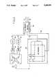
- FIG. 3is a schematic showing how the pointing apparatus may be implemented in accordance with a preferred embodiment of the invention.
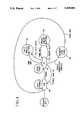
- FIG. 4is a state diagram demonstrating how the operations performed by a user on the keyboard change the operating state of the keyboard so that it can be used as either a keyboard or a pointing device.
- FIG. 5is a flow chart illustrating the software which implements the function of the pointing device of FIGS. 1 and 2.
- FIGS. 6A and 6Billustrate the software in the keyboard microprocessor for detecting and implementing pointing operations, as well as supplying normal keyboard operation.
- FIG. 7illustrates an addition to the computer keyboard device driver permitting precise cursor location in response to a selected character being struck on the keyboard during pointing operations.
- FIG. 1there is shown a keyboard operated computer system.
- the systemincludes a keyboard 11 implemented in accordance with this invention and connected to a computer 12.
- the data entry from keyboard 11is displayed on a CRT display 13 during the normal course of operation of an application program.
- the keyboard 11has a layout of keys which is an industry standard.
- the keyboard 11is shown to have a mouse output cable 17 a keyboard output cable 18 as well as a standard encoded output cable 6 to the computer 12.
- Mouse portsare available on most personal computing systems. Similarly, many application programs have been written to take advantage of pointing and button pressing information supplied through that port. Further discussion of their interface is not necessary.
- the operator who is utilizing an application displayed on the CRT display 13to move the cursor from one position to another.
- This movementmay be accomplished by applying a force in the plane of the keyboard key tops 16 in a direction corresponding to a desired direction of movement for the cursor.
- the amount of displacement of the cursoris proportional to the amount of force applied (within design limits) and the time period over which the force is applied in the plane of the keyboard 11 key top surface 16.
- FIG. 2there is shown how a force applied in the plane of the keyboard key tops 16 may be detected and measured as control signals for subsequent processing into codes which are understandable to a computing system.
- the key switch mounting plate 10is resiliently mounted in the keyboard frame or case 8 and is supported by flexible posts 20 at its distal corners, and a captured bearing 21 at its proximal corners, as seen from the user's point of view.
- the slight amount of force imparted by the finger disposed over a keywill cause flexing of the posts 20, permitting the keyboard surface 10 to move slightly on the captured bearings 21.
- This support arrangementcan be seen to be adequate to support the switch mounting plate against forces applied in the normal direction during key actuation. It can also be seen that if the stiffness of the posts is correctly chosen, small but detectable displacements of the key switch mounting plate 10 with respect to the keyboard case 8 will result from a user applying force to the key tops in any direction in the plane of the key tops. In the illustration, this movement is in the direction of post 20. Post 20 will be slightly deflected as a consequence of these movements. The proximal corners of the keyboard surface 10 will slide over the captured bearing 21. Despite the loose attachment of the key switch plate, there is no danger of its loss as it is held captive between the bearing surface 21 and a keyboard top bezel 24. Keyboard top bezel 24 is shown as part of a conventional wrap-around chassis, capturing both ends of the key switch mounting plate surface 10. It is to be appreciated that other resilient mountings, such as springs or membranes, may be utilized in the practice of the invention.
- a magnet 25Attached to the key switch mounting plate 10 bottom surface is a magnet 25, which will also move when the key switch mounting plate 10 moves.
- the magnet 25is disposed over an array of Hall sensors 27, mounted on the keyboard case 8, which can transduce the variations in magnetic field intensity caused by the displacement of the magnet 25 into functionally corresponding changes in their output current. It is to be assumed that these Hall devices are equipped with current to voltage conversion.
- the array of Hall sensors 27are arranged as differential pairs so that the orthogonal components of the displacement can be translated into voltage magnitudes by differential amplifiers 30 and 31 in FIG. 3, and encoded into binary number values by A/D converters 33 and 34. These numerical values may, in turn, be used by the keyboard processor 35.
- transducerssuch as strain gauges attached to the resilient mounting or keyboard mounting plate, may be utilized in the practice of the invention.
- the sensed strain in the resilient mounting or keyboard mounting platecould be utilized to produce a control signal such as a pointing command signal to the keyboard processor 35 from application to the computer 12. Sensing the strain, also contemplates the situation where the keyboard mounting plate is rigidly mounted to the keyboard case.
- the foregoing apparatusmay be used as a conventional keyboard as shown in FIG. 1.
- the operatorinputs text as usual via the keyboard 11 which may be displayed on the CRT display 13 by the application receiving the keystroke data.
- Control informationsuch as commands or data are entered by the generation of a control signal through the application of a force in the plane of the keyboard key tops as described relative to FIG. 2.
- control information in the form of pointing informationis now described.
- a forceis applied in the plane of the keyboard key tops of FIG. 2, resulting in a displacement of the key switch mounting plate 10 of a magnitude related to that force. This displacement is also exerted upon the magnet 25 of FIG. 3.
- a control signalis thus produced from Hall sensor array 27 in the form of a change in output voltage.
- the common mode of the output voltage of each of the differential pairs of Hall sensors of FIG. 3is rejected by operational amplifiers 30, 31 leaving only component voltages arising from movement in the axis of that pair.
- This voltageis converted into microprocessor readable digital numerical quantities by A/D converters 33, 34.
- A/D converters 33, 34These quantities are used by a program executing on microprocessor 35 to determine which control function has been called for by the user. In this instance, to determine whether or not a pointing operation has been performed by the user.
- the program executing in microprocessor 35 of FIG. 3will respond to these quantities by changing its flow of control to cause pointing information to be sent to the aforementioned application.
- the foregoing function of developing pointing datamakes use of the detection of a force applied to the key top surfaces for switching to the pointing mode. It is possible, using the principles of the present invention, to select other functions in addition to pointing upon the sensing of a force in the direction of the plane of the key top surfaces. These other functions can be similarly encoded wherein the direction of the force, and duration and magnitude of the force may be used to initiate other functions in the computer. It is also possible to build keyboards with integrated pointing device capabilities based on the principles of this invention which utilize techniques other than those described herein for the suspension of the key switch mounting plate and the measurement of the force thereon, without departure from the spirit of the invention.
- the pointing accomplished by the apparatus shown in FIGS. 1 and 3is advantageous in that a typist/computer user need not move fingers from the text entry position to supply pointing information to the computer application program.
- a separate pointing deviceis used, requiring data entry persons to move their hands, or (at best) some fingers, from the text entry position to a dissimilar pointing device operating position.
- permitting the hands to remain on the keyboardit is necessary to provide a means to simulate the mouse button functions on the keyboard and pointing system of FIGS. 1 and 2.
- These functionsmay take the form of detecting while in the pointing mode, when more than one key in a defined group of keys such as keys on either side of the centerline 19 have been simultaneously pressed.
- the operatormay consider the right and left hand sides of the keyboard as two distinct mouse buttons.
- the userneed only be certain that two keys be depressed on either side of the keyboard at substantially the same time to signal the program executing in the keyboard processor that the signal associated with closure of a mouse button should be sent to the application software.
- keyboard switches 36which are scanned in the conventional manner by virtue of X and Y signal buses connected to the keyboard array 36. These keyboard buses 38 and 39 will allow detection of key depressions and identification of which of the keys may have been selected.
- mouse buttonsmay be emulated by the simultaneous depression of at least two keys on either side of the keyboard 11 may be used to simulate the closures of conventional first and second mouse buttons. This, along with data encoding pointing operations in the manner of a conventional mouse, supply the signal provided on a second cable 17 to the mouse input port of the computer 12.
- the keyboard microcomputer 35provides standard keyboard encoded signals on cable 18 to the computer 12.
- the keyboard microprocessormay output the control signals generated by forces applied in the plane of the key tops as cursor key strokes. This encoded information would be supplied to computer 12 by the keyboard connection 18.
- the keyboard microcomputer 35can distinguish the multiple key depressions sensing the operation of a mouse button and encode the same as a mouse operation.
- the keyboard microcomputer 35can distinguish between forces applied to the keyboard, which are intended to be pointing commands from an inadvertent force which may have been applied to the keyboard surface 10, while entering a normal keystroke by examining both the time/magnitude profile of the force, and its coincidence with a keystroke.
- the cursorcan be positioned by supplying positioning information to the application software. It is assumed by way of this example that the application presents a text mode interface, and thus that the keyboard provides positioning information in the form of cursor move key codes. In order to position the cursor 9 in coincidence with a letter of text, the cursor is first positioned near the desired character, following which a search may be triggered. This search may be started by a single key depression corresponding to the displayed alpha numeric character at the desired position for the cursor 9.
- the computermay begin a search procedure to look at all the positions in the vicinity of the cursor in the text memory for the letter I. As memory locations nearby contain two letters I, the computer would identify the closest memory location having the letter I, i.e., the first letter of the word "is”, and position the cursor 9 in coincidence with the closest found letter I. This would then permit a subsequent keystroke to overtype the letter I or insert a character before the I, in accordance with the state of the keyboard (insert or overwrite). In this example it is essential that the user position the cursor closer to the particular "I” desired than to any other "I". Clearly, software may be written which deals with equidistant target characters.
- This search routinemay be employed with or without the mouse function. To leave the pointing function and search function, it is possible to hit the space bar, which will be decoded as a request to leave the pointing mode and reenter a text only mode. The search routine is not available in the text only mode.
- the various modes of operation for the embodiments describedare summarized in the state diagram of FIG. 4. These modes of operation include a keyboard state 40 which the machine assumes after being powered up. A force or push given to the keyboard key tops 16 puts the device in a control mode such as the pointing mode 41, in which the push is converted to pointing information. A particular control mode is implemented by the keyboard microprocessor software. When in the pointing mode, all subsequent forces applied to the surface of the key tops will be converted to pointing information.
- the search modeis entered in state 42 to look for a character in the vicinity of the positioned cursor. Once that character is located, the cursor is moved to the character position, and the keyboard state 40 is re-entered. This permits text composition to continue once the character is located, and the cursor is moved to that location. In the event the character is not found within some preset time period or distance, the cursor is left where it is and the keyboard state 40 is re-entered.
- FIGS. 6A and 6Brepresent the programming steps implemented in the keyboard microcomputer 35.
- FIG. 7illustrates a fragment of a program in the computer 12, necessary for integrating the screen character search into the computer keyboard handling program, for accomplishing a search for a character in the vicinity of the cursor.
- FIG. 5illustrates the overall program architecture in the keyboard microprocessor 35 of FIG. 3 for implementing these functions.
- FIG. 5there is shown the overview organization of the software in the keyboard microprocessor 35, which permits implementation of the foregoing control functions such as pointing, mouse and search functions.
- a power on self-test routineis executed in 51, as is conventional in computer processing systems, such as personal computers.
- the modeis set in block 52 as the keyboard mode.
- initialization datais loaded in step 53 from the computer 12, which identifies parameters for the mouse, such as threshold, and whether mouse data or cursor key codes are to be used to provide positioning information to applications.
- the loaded datais then used to initialize the keyboard microprocessor 35 of FIG. 3 in step 54 in accordance with this selected data.
- the keyboardmay be used to enter either text in the conventional keyboard entry mode or text composition mode or in any of the foregoing control functions such as pointing or mouse modes.
- a keyboard eventis detected at step 55, that event is processed, as shown in FIGS. 6A and 6B
- Step 56comprises a series of steps, as shown in FIGS. 6A and 6B, which encodes and transfers the event to the computer as either a keyboard entry mode function or a control mode function such as a cursor move key depression, a keystroke or mouse data stream.
- the decision block 57determines whether or not any new parameters have been loaded by the host which require reinitialization. In the simplest case it is assumed that there have been no new parameters during one session of use of the device.
- FIG. 6Athere is shown a flow chart illustrating the program steps executed by the keyboard microprocessor 35 to process a keyboard event and encode the same.
- the user's actions on the keyboardcause an event 60 which may either be a keyboard mode or a control mode.
- the event handling routinebegins by determining whether or not the keyboard is in the keyboard mode. If the device is in the keyboard mode, decision block 61 causes the flow of control to pass to decision block 65. This determines whether or not a keystroke has been made. The other possible event is the control mode which is entered in response to the application of a force of a predetermined level in the plane of the key top surface. If such force is not detected, or is detected coincident with a keystroke, the keystroke is encoded in step 68, and sent to the PC in step 69. Each such keystroke provides the basic text composition of the prior art. Following transmission of the keystroke 69, the event handling routine exits 70. This is the exit point of the process block routine 56 of FIG. 5.
- decision block 61again causes the flow of control to pass to decision block 65. If a force is detected on the surface of the keyboard, then decision block 65 causes the flow of control to pass to decision block 66.
- Decision block 66determines whether or not this is above a threshold for operation of a control mode such as the pointing mode. Assuming that it is above the threshold, the pointing mode is entered in step 67 by changing an item in the data structure maintained by the keyboard microprocessor from the condition which indicates keyboard mode to the condition which indicates pointing mode. If the event is not above a predetermined level such as the required threshold, set at initialization 54 of FIG. 5, the event handling routine is exited at 67a.
- Decision block 63routes control to step 71, since a keystroke has not been detected, wherein each of the analog to digital converters 33, 34 of FIG. 3 is read. This provides a reading indicative of the amount of force in each of two coordinate directions detected by the Hall devices in the hall sensor 27. Assuming that the mouse mode has not been selected, as determined in decision block 72, these readings are added to cumulative totals of X and Y force measurements in step 77, X and Y denoting each of the directions in which the pair of differential Hall devices are oriented.
- decision block 78it is determined whether or not the cumulative amount of force over time exceeds that of a threshold or predetermined level. If so, the value is encoded in step 79.
- the encoded displacement along the axis Xis sent in 80 to the PC keyboard port in the form of cursor movement keystroke codes as the mouse mode has not been set.
- the portion of the accumulated X valueis subtracted in step 81 from the cumulative total to establish a new, correct cumulative X. Control is then passed to decision block 85 to deal with the cumulative Y count is the same way. Control would have also been passed to decision block 85 if the cumulative X count had not exceeded the threshold as determined at decision block 78.
- a similar encoding of force detected along a Y axisis affected.
- decision block 85the cumulative total of force measured along the axis defined by the orthogonal pair of Hall devices shown in FIGS. 2 and 3 is compared against a threshold or predetermined level. If this threshold is exceeded, the result is encoded in step 82 and sent to the PC in step 83. The encoded quantity is then subtracted from the cumulative total in step 84, and the event handler is then exited in 86. If the Y threshold value was not exceeded in decision block 85, the event handler is likewise exited at step 86.
- each force measurement while in the pointing modeis encoded as cursor movement keystrokes, identifying the amount of displacement in two orthogonal directions for the cursor.
- step 73to encode the content of the cumulative X and Y counts as a mouse data stream format datum. This datum is routed to the mouse port of the PC at step 75 and the event handler is exited at 76.
- FIG. 6Bthere are shown additional steps executed by the keyboard microprocessor 35 when executing the event handler in the pointing mode to effect a simulation of two mouse buttons, or send a message requesting a search for a nearby character, or to effect a return to the keyboard mode.
- the userhas depressed one or more keys. If one key is depressed which is the space bar, then decision block 89 routes the control flow of the program to function 94 which takes the system out of the control mode, in this instance the pointing mode and returns it to the keyboard mode. Following this mode change, the event handler returns control as shown in block 95.
- decision block 88determines whether a single key or multiple keys were depressed. If a single key was depressed control flow is routed to block 90 and an escape code message is sent to the PC in step 90. After this message is sent, the event handler is exited 91 in the familiar manner.
- the escape code messageis received by the keyboard interrupt handler of the PC, and contains the character to be searched for among the displayed text.
- the keyboard interrupt handler in the PCcan be conventional except insofar as its behavior when the escape message is received.
- FIG. 7shows the additional program flow control needed to process keyboard streams containing escape messages.
- the computer 12upon receiving this message, conducts a search 117 to locate a character identified by the keystroke, within the display memory, which is closest to the coarsely positioned cursor.
- This searchcan be performed by any of several methods commonly known to those skilled in the art.
- this routinereaches decision block 118 where, if the search is successful, the move cursor routine 119 positions the cursor. If the search is unsuccessful, the keyboard buffer 120 is flushed of the escape sequence without any cursor repositioning. The remainder of the keyboard interrupt handler may then execute according to its control flow.
- control flowis routed to decision block 100, where the decision is made whether or not most of the depressed keys are on the left or right of the centerline, thereby identifying whether or not a left or a right mouse button has been selected.
- decision block 100determines whether or not most of the depressed keys are on the left or right of the centerline, thereby identifying whether or not a left or a right mouse button has been selected.
- apparatuswhich establishes a different control function for a keyboard by sensing the presence of a lateral force having a given or predetermined range of magnitudes.
- Thismay be implemented as one of many control functions or pointing functions such as a cursor movement or mouse function, permitting mouse functions to be emulated without additional keys or unfamiliar manual operation.
Landscapes
- Engineering & Computer Science (AREA)
- General Engineering & Computer Science (AREA)
- Theoretical Computer Science (AREA)
- Human Computer Interaction (AREA)
- Physics & Mathematics (AREA)
- General Physics & Mathematics (AREA)
- Input From Keyboards Or The Like (AREA)
Abstract
Description
Claims (11)
Priority Applications (4)
| Application Number | Priority Date | Filing Date | Title |
|---|---|---|---|
| US07/545,255US5269004A (en) | 1990-06-28 | 1990-06-28 | System for integrating pointing functions into computer keyboard with lateral movement of keyswitch mounting plate causing strain and control signal |
| DE69123495TDE69123495T2 (en) | 1990-06-28 | 1991-02-13 | Device and method for integrating pointer functions into a computer keyboard |
| EP91101993AEP0463288B1 (en) | 1990-06-28 | 1991-02-13 | Apparatus and method for integrating pointing functions into a computer keyboard |
| JP3115882AJP2635845B2 (en) | 1990-06-28 | 1991-05-21 | Apparatus and method for integrating pointing functions into a computer keyboard |
Applications Claiming Priority (1)
| Application Number | Priority Date | Filing Date | Title |
|---|---|---|---|
| US07/545,255US5269004A (en) | 1990-06-28 | 1990-06-28 | System for integrating pointing functions into computer keyboard with lateral movement of keyswitch mounting plate causing strain and control signal |
Publications (1)
| Publication Number | Publication Date |
|---|---|
| US5269004Atrue US5269004A (en) | 1993-12-07 |
Family
ID=24175492
Family Applications (1)
| Application Number | Title | Priority Date | Filing Date |
|---|---|---|---|
| US07/545,255Expired - LifetimeUS5269004A (en) | 1990-06-28 | 1990-06-28 | System for integrating pointing functions into computer keyboard with lateral movement of keyswitch mounting plate causing strain and control signal |
Country Status (4)
| Country | Link |
|---|---|
| US (1) | US5269004A (en) |
| EP (1) | EP0463288B1 (en) |
| JP (1) | JP2635845B2 (en) |
| DE (1) | DE69123495T2 (en) |
Cited By (39)
| Publication number | Priority date | Publication date | Assignee | Title |
|---|---|---|---|---|
| US5502276A (en)* | 1994-03-21 | 1996-03-26 | International Business Machines Corporation | Electronic musical keyboard instruments comprising an immovable pointing stick |
| US5515044A (en)* | 1994-04-18 | 1996-05-07 | Sensormatic Electronics Corporation | Controller apparatus using force sensing resistors |
| US5574891A (en)* | 1994-09-27 | 1996-11-12 | Acer Peripherals, Inc. | Method for managing the input codes from keyboard and pointing device |
| US5579238A (en)* | 1994-10-21 | 1996-11-26 | Krugman; Michael | Instrumented computer keyboard for prevention of injury |
| US5627566A (en)* | 1991-06-06 | 1997-05-06 | Litschel; Dietmar | Keyboard |
| US5661505A (en)* | 1995-01-13 | 1997-08-26 | Livits; Eric A. | Single hand-controlled computer input device |
| US5673040A (en)* | 1991-04-10 | 1997-09-30 | Kinesis Corporation | Ergonomic keyboard apparatus |
| US5675361A (en)* | 1995-08-23 | 1997-10-07 | Santilli; Donald S. | Computer keyboard pointing device |
| US5680154A (en)* | 1994-05-25 | 1997-10-21 | Alps Electric Co., Ltd. | Operation inputting apparatus |
| US5689253A (en)* | 1991-04-10 | 1997-11-18 | Kinesis Corporation | Ergonomic keyboard apparatus |
| US5691716A (en)* | 1993-07-29 | 1997-11-25 | Crowley; Robert J. | Keyboard with keys for moving cursor |
| US5694123A (en)* | 1994-09-15 | 1997-12-02 | International Business Machines Corporation | Keyboard with integrated pointing device and click buttons with lock down for drag operation in a computer system with a graphical user interface |
| US5712660A (en)* | 1995-10-19 | 1998-01-27 | Canon Business Machines, Inc. | Cursor control stick |
| US5880685A (en)* | 1993-07-23 | 1999-03-09 | Weeks; James A. | Computer keyboard with accessory platform |
| US20020025837A1 (en)* | 2000-05-22 | 2002-02-28 | Levy David H. | Input devices and their use |
| US6400285B1 (en)* | 1992-10-08 | 2002-06-04 | Henry Gifford | Ergonomic keyboard |
| US6520699B2 (en)* | 2001-02-16 | 2003-02-18 | Toshiyasu Abe | Keyboard |
| US20030160712A1 (en)* | 2002-02-27 | 2003-08-28 | Digit Wireless, Llc, A Delaware Corporation | Keypad construction |
| US6614421B1 (en)* | 1998-05-22 | 2003-09-02 | International Business Machines Corporation | Keyboard having buttons positioned for operation by heel of hand |
| US20040031673A1 (en)* | 2002-05-23 | 2004-02-19 | Levy David H. | Keypads and key switches |
| US6781077B2 (en) | 2000-12-14 | 2004-08-24 | Think Outside, Inc. | Keyswitch and actuator structure |
| US20050063757A1 (en)* | 2003-07-08 | 2005-03-24 | Ntt Docomo, Inc. | Input key and input apparatus |
| US20050083215A1 (en)* | 1993-07-29 | 2005-04-21 | Crowley Robert J. | Keyboard with keys for moving cursor |
| US20060082548A1 (en)* | 2004-10-20 | 2006-04-20 | Kodama Robert R | Computer keyboard with pointer control |
| US20070222761A1 (en)* | 2006-03-21 | 2007-09-27 | Hon Hai Precision Industry Co., Ltd. | Apparatus for defining keystroke values of keyboard, keyboard with definable keystroke values, and method therefor |
| US20070249397A1 (en)* | 2006-04-20 | 2007-10-25 | Samsung Electro-Mechanics Co., Ltd. | Modular input device and portable handset and remote control provided with the same |
| USD585063S1 (en) | 2007-11-27 | 2009-01-20 | Kinesis Corporation | Keyboard |
| US20100149099A1 (en)* | 2008-12-12 | 2010-06-17 | John Greer Elias | Motion sensitive mechanical keyboard |
| US20100148995A1 (en)* | 2008-12-12 | 2010-06-17 | John Greer Elias | Touch Sensitive Mechanical Keyboard |
| US20100268994A1 (en)* | 2009-04-17 | 2010-10-21 | Primax Electronics Ltd. | Automatic keyboard testing system |
| US20110210918A1 (en)* | 2004-10-20 | 2011-09-01 | Kodama Robert R | Computer keyboard with pointer control |
| US20120019444A1 (en)* | 2010-07-23 | 2012-01-26 | Primax Electronics Ltd. | Keyboard with mode-switching function |
| US8581870B2 (en) | 2011-12-06 | 2013-11-12 | Apple Inc. | Touch-sensitive button with two levels |
| US9041652B2 (en) | 2011-09-14 | 2015-05-26 | Apple Inc. | Fusion keyboard |
| US9454239B2 (en) | 2011-09-14 | 2016-09-27 | Apple Inc. | Enabling touch events on a touch sensitive mechanical keyboard |
| US20170123508A1 (en)* | 2015-10-29 | 2017-05-04 | Dell Products L.P. | Low Profile Information Handling System Keyboard |
| US20170123462A1 (en)* | 2015-10-29 | 2017-05-04 | Dell Products L.P. | Low Profile Information Handling System Keyboard |
| US9785251B2 (en) | 2011-09-14 | 2017-10-10 | Apple Inc. | Actuation lock for a touch sensitive mechanical keyboard |
| WO2021093757A1 (en)* | 2019-11-12 | 2021-05-20 | 珠海市学思电子科技有限公司 | Magnetomotive keyboard and working method for magnetomotive keyboard |
Families Citing this family (2)
| Publication number | Priority date | Publication date | Assignee | Title |
|---|---|---|---|---|
| CN101241397B (en)* | 2007-02-07 | 2012-03-07 | 罗伯特·博世有限公司 | Keyboard possessing mouse function and its input method |
| AT523004B1 (en)* | 2019-09-26 | 2022-01-15 | Youhoosoft Gmbh | Process for converting sensor events |
Citations (8)
| Publication number | Priority date | Publication date | Assignee | Title |
|---|---|---|---|---|
| US4357646A (en)* | 1981-01-21 | 1982-11-02 | Illinois Tool Works Inc. | Capacitive keyswitch with overtravel mechanism on moveable plate |
| US4680577A (en)* | 1983-11-28 | 1987-07-14 | Tektronix, Inc. | Multipurpose cursor control keyswitch |
| US4826123A (en)* | 1983-05-16 | 1989-05-02 | Knoll International, Inc. | Adjustable keyboard support |
| US4857840A (en)* | 1984-06-18 | 1989-08-15 | Michel Lanchais | Information and guiding system including a portable receiver device having an electromagnetic wave antenna and magnetic field sensor |
| US4899137A (en)* | 1987-09-26 | 1990-02-06 | Aeg Olympia Aktiengesellschaft | Arrangement for the input and processing of characters and/or graphic patterns |
| US5034740A (en)* | 1988-09-30 | 1991-07-23 | Siemens Aktiengesellschaft | Capacitive card module |
| US5036743A (en)* | 1988-11-30 | 1991-08-06 | Kabushiki Kaisha Kawai Gakki Seisakusho | Keyboard device for electronic musical instrument |
| US5124689A (en)* | 1989-09-26 | 1992-06-23 | Home Row, Inc. | Integrated keyboard and pointing device system |
Family Cites Families (4)
| Publication number | Priority date | Publication date | Assignee | Title |
|---|---|---|---|---|
| JPS59123916A (en)* | 1982-12-29 | 1984-07-17 | Fujitsu Ltd | Keyboard method for cursor operation |
| US4459578A (en)* | 1983-01-13 | 1984-07-10 | Atari, Inc. | Finger control joystick utilizing Hall effect |
| JPS6380631U (en)* | 1986-11-13 | 1988-05-27 | ||
| JPH01267714A (en)* | 1988-04-19 | 1989-10-25 | Mitsubishi Electric Corp | Input device |
- 1990
- 1990-06-28USUS07/545,255patent/US5269004A/ennot_activeExpired - Lifetime
- 1991
- 1991-02-13EPEP91101993Apatent/EP0463288B1/ennot_activeExpired - Lifetime
- 1991-02-13DEDE69123495Tpatent/DE69123495T2/ennot_activeExpired - Fee Related
- 1991-05-21JPJP3115882Apatent/JP2635845B2/ennot_activeExpired - Lifetime
Patent Citations (8)
| Publication number | Priority date | Publication date | Assignee | Title |
|---|---|---|---|---|
| US4357646A (en)* | 1981-01-21 | 1982-11-02 | Illinois Tool Works Inc. | Capacitive keyswitch with overtravel mechanism on moveable plate |
| US4826123A (en)* | 1983-05-16 | 1989-05-02 | Knoll International, Inc. | Adjustable keyboard support |
| US4680577A (en)* | 1983-11-28 | 1987-07-14 | Tektronix, Inc. | Multipurpose cursor control keyswitch |
| US4857840A (en)* | 1984-06-18 | 1989-08-15 | Michel Lanchais | Information and guiding system including a portable receiver device having an electromagnetic wave antenna and magnetic field sensor |
| US4899137A (en)* | 1987-09-26 | 1990-02-06 | Aeg Olympia Aktiengesellschaft | Arrangement for the input and processing of characters and/or graphic patterns |
| US5034740A (en)* | 1988-09-30 | 1991-07-23 | Siemens Aktiengesellschaft | Capacitive card module |
| US5036743A (en)* | 1988-11-30 | 1991-08-06 | Kabushiki Kaisha Kawai Gakki Seisakusho | Keyboard device for electronic musical instrument |
| US5124689A (en)* | 1989-09-26 | 1992-06-23 | Home Row, Inc. | Integrated keyboard and pointing device system |
Cited By (62)
| Publication number | Priority date | Publication date | Assignee | Title |
|---|---|---|---|---|
| US5689253A (en)* | 1991-04-10 | 1997-11-18 | Kinesis Corporation | Ergonomic keyboard apparatus |
| US5673040A (en)* | 1991-04-10 | 1997-09-30 | Kinesis Corporation | Ergonomic keyboard apparatus |
| US5627566A (en)* | 1991-06-06 | 1997-05-06 | Litschel; Dietmar | Keyboard |
| US6400285B1 (en)* | 1992-10-08 | 2002-06-04 | Henry Gifford | Ergonomic keyboard |
| US5880685A (en)* | 1993-07-23 | 1999-03-09 | Weeks; James A. | Computer keyboard with accessory platform |
| US7589712B2 (en)* | 1993-07-29 | 2009-09-15 | Crowley Robert J | Keyboard with keys for moving cursor |
| US20050083215A1 (en)* | 1993-07-29 | 2005-04-21 | Crowley Robert J. | Keyboard with keys for moving cursor |
| US5691716A (en)* | 1993-07-29 | 1997-11-25 | Crowley; Robert J. | Keyboard with keys for moving cursor |
| US5502276A (en)* | 1994-03-21 | 1996-03-26 | International Business Machines Corporation | Electronic musical keyboard instruments comprising an immovable pointing stick |
| US5515044A (en)* | 1994-04-18 | 1996-05-07 | Sensormatic Electronics Corporation | Controller apparatus using force sensing resistors |
| US5877749A (en)* | 1994-05-25 | 1999-03-02 | Alps Electric Co., Ltd. | Operation inputting apparatus |
| US5680154A (en)* | 1994-05-25 | 1997-10-21 | Alps Electric Co., Ltd. | Operation inputting apparatus |
| US5694123A (en)* | 1994-09-15 | 1997-12-02 | International Business Machines Corporation | Keyboard with integrated pointing device and click buttons with lock down for drag operation in a computer system with a graphical user interface |
| US5574891A (en)* | 1994-09-27 | 1996-11-12 | Acer Peripherals, Inc. | Method for managing the input codes from keyboard and pointing device |
| US5579238A (en)* | 1994-10-21 | 1996-11-26 | Krugman; Michael | Instrumented computer keyboard for prevention of injury |
| US5661505A (en)* | 1995-01-13 | 1997-08-26 | Livits; Eric A. | Single hand-controlled computer input device |
| WO1997033145A1 (en)* | 1995-08-21 | 1997-09-12 | Michael Krugman | Instrumented computer keyboard for prevention of injury |
| US5675361A (en)* | 1995-08-23 | 1997-10-07 | Santilli; Donald S. | Computer keyboard pointing device |
| US5712660A (en)* | 1995-10-19 | 1998-01-27 | Canon Business Machines, Inc. | Cursor control stick |
| US6614421B1 (en)* | 1998-05-22 | 2003-09-02 | International Business Machines Corporation | Keyboard having buttons positioned for operation by heel of hand |
| US8094806B2 (en) | 2000-05-22 | 2012-01-10 | Nuance Communications, Inc. | Input devices and their use |
| US20020025837A1 (en)* | 2000-05-22 | 2002-02-28 | Levy David H. | Input devices and their use |
| US7391861B2 (en) | 2000-05-22 | 2008-06-24 | Digit Wireless, Llc | Input devices and their use |
| US20070256915A1 (en)* | 2000-05-22 | 2007-11-08 | Digit Wireless, Inc. | Input Devices And Their Use |
| US6781077B2 (en) | 2000-12-14 | 2004-08-24 | Think Outside, Inc. | Keyswitch and actuator structure |
| US6520699B2 (en)* | 2001-02-16 | 2003-02-18 | Toshiyasu Abe | Keyboard |
| US20030160712A1 (en)* | 2002-02-27 | 2003-08-28 | Digit Wireless, Llc, A Delaware Corporation | Keypad construction |
| US7126498B2 (en) | 2002-02-27 | 2006-10-24 | Digit Wireless, Llc | Keypad construction |
| US20040031673A1 (en)* | 2002-05-23 | 2004-02-19 | Levy David H. | Keypads and key switches |
| US6911608B2 (en) | 2002-05-23 | 2005-06-28 | Digit Wireless, Llc | Keypads and key switches |
| US7336206B2 (en)* | 2003-07-08 | 2008-02-26 | Ntt Docomo, Inc. | Input key and input apparatus |
| US20050063757A1 (en)* | 2003-07-08 | 2005-03-24 | Ntt Docomo, Inc. | Input key and input apparatus |
| US7903088B2 (en) | 2004-10-20 | 2011-03-08 | Kodama Robert R | Computer keyboard with pointer control |
| US20060082548A1 (en)* | 2004-10-20 | 2006-04-20 | Kodama Robert R | Computer keyboard with pointer control |
| US9098118B2 (en) | 2004-10-20 | 2015-08-04 | Robert R. Kodama | Computer keyboard with pointer control |
| US20110210918A1 (en)* | 2004-10-20 | 2011-09-01 | Kodama Robert R | Computer keyboard with pointer control |
| US20070222761A1 (en)* | 2006-03-21 | 2007-09-27 | Hon Hai Precision Industry Co., Ltd. | Apparatus for defining keystroke values of keyboard, keyboard with definable keystroke values, and method therefor |
| US20070249397A1 (en)* | 2006-04-20 | 2007-10-25 | Samsung Electro-Mechanics Co., Ltd. | Modular input device and portable handset and remote control provided with the same |
| USRE43485E1 (en) | 2007-11-27 | 2012-06-26 | Kinesis Corporation | Keyboard |
| USD585063S1 (en) | 2007-11-27 | 2009-01-20 | Kinesis Corporation | Keyboard |
| US20100148995A1 (en)* | 2008-12-12 | 2010-06-17 | John Greer Elias | Touch Sensitive Mechanical Keyboard |
| US20100149099A1 (en)* | 2008-12-12 | 2010-06-17 | John Greer Elias | Motion sensitive mechanical keyboard |
| US11036307B2 (en) | 2008-12-12 | 2021-06-15 | Apple Inc. | Touch sensitive mechanical keyboard |
| US10585493B2 (en) | 2008-12-12 | 2020-03-10 | Apple Inc. | Touch sensitive mechanical keyboard |
| US20100268994A1 (en)* | 2009-04-17 | 2010-10-21 | Primax Electronics Ltd. | Automatic keyboard testing system |
| US8117504B2 (en)* | 2009-04-17 | 2012-02-14 | Primax Electronics Ltd. | Automatic keyboard testing system |
| US20120019444A1 (en)* | 2010-07-23 | 2012-01-26 | Primax Electronics Ltd. | Keyboard with mode-switching function |
| US9785251B2 (en) | 2011-09-14 | 2017-10-10 | Apple Inc. | Actuation lock for a touch sensitive mechanical keyboard |
| US10466805B2 (en) | 2011-09-14 | 2019-11-05 | Apple Inc. | Actuation lock for a touch sensitive input device |
| US9454239B2 (en) | 2011-09-14 | 2016-09-27 | Apple Inc. | Enabling touch events on a touch sensitive mechanical keyboard |
| US11119582B2 (en) | 2011-09-14 | 2021-09-14 | Apple Inc. | Actuation lock for a touch sensitive input device |
| US9041652B2 (en) | 2011-09-14 | 2015-05-26 | Apple Inc. | Fusion keyboard |
| US9400581B2 (en) | 2011-12-06 | 2016-07-26 | Apple Inc. | Touch-sensitive button with two levels |
| US9904410B2 (en) | 2011-12-06 | 2018-02-27 | Apple Inc. | Touch-sensitive button with two levels |
| US8581870B2 (en) | 2011-12-06 | 2013-11-12 | Apple Inc. | Touch-sensitive button with two levels |
| US8933905B2 (en) | 2011-12-06 | 2015-01-13 | Apple Inc. | Touch-sensitive button with two levels |
| US10296136B2 (en) | 2011-12-06 | 2019-05-21 | Apple Inc. | Touch-sensitive button with two levels |
| US20170123462A1 (en)* | 2015-10-29 | 2017-05-04 | Dell Products L.P. | Low Profile Information Handling System Keyboard |
| US10037087B2 (en)* | 2015-10-29 | 2018-07-31 | Dell Products L.P. | Low profile information handling system keyboard |
| US9964996B2 (en)* | 2015-10-29 | 2018-05-08 | Dell Products L.P. | Low profile information handling system keyboard |
| US20170123508A1 (en)* | 2015-10-29 | 2017-05-04 | Dell Products L.P. | Low Profile Information Handling System Keyboard |
| WO2021093757A1 (en)* | 2019-11-12 | 2021-05-20 | 珠海市学思电子科技有限公司 | Magnetomotive keyboard and working method for magnetomotive keyboard |
Also Published As
| Publication number | Publication date |
|---|---|
| JPH08202481A (en) | 1996-08-09 |
| JP2635845B2 (en) | 1997-07-30 |
| EP0463288B1 (en) | 1996-12-11 |
| EP0463288A1 (en) | 1992-01-02 |
| DE69123495T2 (en) | 1997-06-12 |
| DE69123495D1 (en) | 1997-01-23 |
Similar Documents
| Publication | Publication Date | Title |
|---|---|---|
| US5269004A (en) | System for integrating pointing functions into computer keyboard with lateral movement of keyswitch mounting plate causing strain and control signal | |
| US4680577A (en) | Multipurpose cursor control keyswitch | |
| US5909211A (en) | Touch pad overlay driven computer system | |
| US6323845B1 (en) | Single finger controlled computer input apparatus and method | |
| EP0394614B1 (en) | Advanced user interface | |
| US5748185A (en) | Touchpad with scroll and pan regions | |
| US5912659A (en) | Graphics display pointer with integrated selection | |
| CN1113287C (en) | Method and apparatus for multiple mode hand write input and hand guide control of computer equipment | |
| US5696535A (en) | Graphics display pointer with integrated selection | |
| JPH04503726A (en) | Integrated keyboard and pointing device system | |
| JPH05204353A (en) | Integrated keyboard equipped with automatic mode change and pointing device system | |
| GB2154349A (en) | Touchscreen apparatus | |
| WO1998000775A9 (en) | Touchpad with scroll and pan regions | |
| US20030210233A1 (en) | Computer user interface input device and a method of using same | |
| US5945979A (en) | Combined digital and analog cursor control | |
| KR20020069694A (en) | Space keyboard system using force feedback and its method for inputting information | |
| US20090153487A1 (en) | Data input device having a plurality of key stick devices for fast typing and method thereof | |
| US5973622A (en) | Keyboard with a two-dimensional actuator for generating direction signals | |
| US20060109251A1 (en) | Combined keyboard and movement detection system | |
| JPH0954646A (en) | Virtual keyboard device and key input control method | |
| JP2957368B2 (en) | Coordinate input device switching device | |
| KR100503056B1 (en) | Touch pad processing apparatus, method thereof and touch pad module in computer system | |
| JP2500283B2 (en) | Virtual space keyboard device | |
| KR940006811B1 (en) | Intergrated keyboard and pointing device system | |
| KR102274780B1 (en) | Input device according to six axis movement of foot |
Legal Events
| Date | Code | Title | Description |
|---|---|---|---|
| AS | Assignment | Owner name:INTERNATIONAL BUSINESS MACHINES CORPORATION, A CO Free format text:ASSIGNMENT OF ASSIGNORS INTEREST.;ASSIGNORS:COMERFORD, LIAM D.;LAIBINIS, JOSEPH J.;REEL/FRAME:005367/0245 Effective date:19900628 | |
| STCF | Information on status: patent grant | Free format text:PATENTED CASE | |
| FPAY | Fee payment | Year of fee payment:4 | |
| FPAY | Fee payment | Year of fee payment:8 | |
| FEPP | Fee payment procedure | Free format text:PAYOR NUMBER ASSIGNED (ORIGINAL EVENT CODE: ASPN); ENTITY STATUS OF PATENT OWNER: LARGE ENTITY | |
| FPAY | Fee payment | Year of fee payment:12 | |
| AS | Assignment | Owner name:LENOVO (SINGAPORE) PTE LTD.,SINGAPORE Free format text:ASSIGNMENT OF ASSIGNORS INTEREST;ASSIGNOR:INTERNATIONAL BUSINESS MACHINES CORPORATION;REEL/FRAME:016891/0507 Effective date:20050520 Owner name:LENOVO (SINGAPORE) PTE LTD., SINGAPORE Free format text:ASSIGNMENT OF ASSIGNORS INTEREST;ASSIGNOR:INTERNATIONAL BUSINESS MACHINES CORPORATION;REEL/FRAME:016891/0507 Effective date:20050520 |