US5268981A - Optical fiber connector methods using a substrate with an aperture - Google Patents
Optical fiber connector methods using a substrate with an apertureDownload PDFInfo
- Publication number
- US5268981A US5268981AUS07/976,745US97674592AUS5268981AUS 5268981 AUS5268981 AUS 5268981AUS 97674592 AUS97674592 AUS 97674592AUS 5268981 AUS5268981 AUS 5268981A
- Authority
- US
- United States
- Prior art keywords
- optical fiber
- aperture
- support members
- substrate
- optical
- Prior art date
- Legal status (The legal status is an assumption and is not a legal conclusion. Google has not performed a legal analysis and makes no representation as to the accuracy of the status listed.)
- Expired - Fee Related
Links
Images


Classifications
- G—PHYSICS
- G02—OPTICS
- G02B—OPTICAL ELEMENTS, SYSTEMS OR APPARATUS
- G02B6/00—Light guides; Structural details of arrangements comprising light guides and other optical elements, e.g. couplings
- G02B6/24—Coupling light guides
- G02B6/42—Coupling light guides with opto-electronic elements
- G02B6/43—Arrangements comprising a plurality of opto-electronic elements and associated optical interconnections
- G—PHYSICS
- G02—OPTICS
- G02B—OPTICAL ELEMENTS, SYSTEMS OR APPARATUS
- G02B6/00—Light guides; Structural details of arrangements comprising light guides and other optical elements, e.g. couplings
- G02B6/24—Coupling light guides
- G02B6/36—Mechanical coupling means
- G02B6/38—Mechanical coupling means having fibre to fibre mating means
- G02B6/3807—Dismountable connectors, i.e. comprising plugs
- G02B6/3833—Details of mounting fibres in ferrules; Assembly methods; Manufacture
- G02B6/3834—Means for centering or aligning the light guide within the ferrule
- G02B6/3838—Means for centering or aligning the light guide within the ferrule using grooves for light guides
- G02B6/3839—Means for centering or aligning the light guide within the ferrule using grooves for light guides for a plurality of light guides
- G—PHYSICS
- G02—OPTICS
- G02B—OPTICAL ELEMENTS, SYSTEMS OR APPARATUS
- G02B6/00—Light guides; Structural details of arrangements comprising light guides and other optical elements, e.g. couplings
- G02B6/24—Coupling light guides
- G02B6/36—Mechanical coupling means
- G02B6/38—Mechanical coupling means having fibre to fibre mating means
- G02B6/3807—Dismountable connectors, i.e. comprising plugs
- G02B6/3873—Connectors using guide surfaces for aligning ferrule ends, e.g. tubes, sleeves, V-grooves, rods, pins, balls
- G02B6/3885—Multicore or multichannel optical connectors, i.e. one single ferrule containing more than one fibre, e.g. ribbon type
- G—PHYSICS
- G02—OPTICS
- G02B—OPTICAL ELEMENTS, SYSTEMS OR APPARATUS
- G02B6/00—Light guides; Structural details of arrangements comprising light guides and other optical elements, e.g. couplings
- G02B6/24—Coupling light guides
- G02B6/36—Mechanical coupling means
- G02B6/38—Mechanical coupling means having fibre to fibre mating means
- G02B6/3807—Dismountable connectors, i.e. comprising plugs
- G02B6/3897—Connectors fixed to housings, casing, frames or circuit boards
- G—PHYSICS
- G02—OPTICS
- G02B—OPTICAL ELEMENTS, SYSTEMS OR APPARATUS
- G02B6/00—Light guides; Structural details of arrangements comprising light guides and other optical elements, e.g. couplings
- G02B6/24—Coupling light guides
- G02B6/36—Mechanical coupling means
- G02B6/3608—Fibre wiring boards, i.e. where fibres are embedded or attached in a pattern on or to a substrate, e.g. flexible sheets
- G—PHYSICS
- G02—OPTICS
- G02B—OPTICAL ELEMENTS, SYSTEMS OR APPARATUS
- G02B6/00—Light guides; Structural details of arrangements comprising light guides and other optical elements, e.g. couplings
- G02B6/24—Coupling light guides
- G02B6/36—Mechanical coupling means
- G02B6/38—Mechanical coupling means having fibre to fibre mating means
- G02B6/3807—Dismountable connectors, i.e. comprising plugs
- G02B6/3833—Details of mounting fibres in ferrules; Assembly methods; Manufacture
- G02B6/3865—Details of mounting fibres in ferrules; Assembly methods; Manufacture fabricated by using moulding techniques
- G—PHYSICS
- G02—OPTICS
- G02B—OPTICAL ELEMENTS, SYSTEMS OR APPARATUS
- G02B6/00—Light guides; Structural details of arrangements comprising light guides and other optical elements, e.g. couplings
- G02B6/24—Coupling light guides
- G02B6/36—Mechanical coupling means
- G02B6/38—Mechanical coupling means having fibre to fibre mating means
- G02B6/3807—Dismountable connectors, i.e. comprising plugs
- G02B6/3873—Connectors using guide surfaces for aligning ferrule ends, e.g. tubes, sleeves, V-grooves, rods, pins, balls
- G—PHYSICS
- G02—OPTICS
- G02B—OPTICAL ELEMENTS, SYSTEMS OR APPARATUS
- G02B6/00—Light guides; Structural details of arrangements comprising light guides and other optical elements, e.g. couplings
- G02B6/24—Coupling light guides
- G02B6/36—Mechanical coupling means
- G02B6/38—Mechanical coupling means having fibre to fibre mating means
- G02B6/3807—Dismountable connectors, i.e. comprising plugs
- G02B6/3887—Anchoring optical cables to connector housings, e.g. strain relief features
- G02B6/38875—Protection from bending or twisting
Definitions
- This inventionrelates to optical fiber interconnections and more particularly, to techniques for making connections to optical backplanes.
- the patent applicationdescribes how a computer is used to provide optical fibers of the appropriate length between input and output ports, or tabs of the optical backplane, it being important for optical transmission reliability that there not be minute deviations in the prescribed lengths of the various lines.
- the fiber pathsare made of a single optical fiber that is looped between different output tabs during the fabrication so that a single test can be used to determine satisfactory optical transmission. After the test, the loops are severed by cutting through the substrate to define the various output tabs.
- An optical backplaneis made by making an aperture at each of the output ports.
- the optical fiberis adhered to the substrate such that all of the optical fiber segments of each output port traverse the aperture of that port.
- the optical fiber segments traversing each apertureare contained between a pair of first optical fiber support members on opposite sides of the array of fiber segments.
- the support membersare next encapsulated in a plastic encapsulation, preferably by injection molding.
- the encapsulated support members and substrateare cut transversely to the optical fiber segments, and the exposed ends of the optical fiber segments are polished. This provides a connector for the output port to which a matching array of optical fibers contained between opposite second support members can be abutted and aligned so as to transmit light from the output port to the second optical fibers.
- the optical fiber support membersare made in a known manner from crystalline material so as to have individual grooves for supporting the individual optical fiber segments.
- the support membersalso contain an alignment aperture, and identical second optical fiber support members are made to receive alignment pins adapted to be inserted into a matching alignment apertures for aligning the optical fiber segments to the second optical fibers.
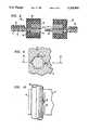
- FIG. 1is a top view of part of an optical backplane showing an output port
- FIG. 2is a sectional elevational view of the optical backplane of FIG. l;
- FIG. 3shows the apparatus of FIG. 2 after fiber support members have been applied
- FIG. 4is a view taken along lines 4--4 of FIG. 3;
- FIG. 5is a view taken along lines 5--5 of FIG. 4;
- FIGS. 6 and 7are views of the apparatus of FIG. 3 at subsequent stages of fabrication
- FIG. 8is a sectional view of the apparatus of FIG. 7 at a subsequent stage of fabrication showing how optical fiber connections can be made;
- FIG. 9is a sectional view showing how an alignment pin such as that shown in FIG. 8 can be used for aligning optical fiber.
- FIG. 10is a view taken along lines 10--10 of FIG. 9.
- FIG. 1there is shown a top view of an optical backplane segment comprising a substrate 11 upon which an optical fiber 12 has been routed in a manner described in the aforementioned Burack et al. patent application. That application describes how single optical fiber can be repeatedly looped and directed over an output port output tab region by a routing machine. After completion of the routing, the transmission of the fiber can be tested by directing light through it, and thereafter the output port 13 may be severed transversely to the optical fiber so that a plurality of optical fiber paths are defined on the optical backplane substrate 11.
- optical backplanesfrom a single strand of optical fiber 12 such that the substrate to the left of output port region 13 constitutes one optical backplane and the portion to the right of output port 13 constitutes another optical backplane.
- the portion to the right of output port 13may merely be an area in which loops are formed in optical fiber 12, which will eventually be severed and wasted.
- a typical optical backplanecontains a number of output ports, only one of which is shown in FIG. 1 for reasons of simplicity and clarity.
- an aperture 15is made in substrate 11 in the output port region. As shown in FIG. 2 this aperture may be filled with a temporary spacer 16 so that the optical fiber 12 may be routed as shown in FIG. 1 without encountering any physical discontinuity.
- the substrate 11include on an upper surface a pressure-sensitive adhesive for causing the adherence of optical fiber 12, no such adhesive is normally included on the upper surface of temporary portion 16.
- the next step, illustrated in FIGs. 3 and 4is to locate a matching pair of optical fiber support members 18 and 19 on opposite sides of the fiber segments extending across aperture 15.
- the support members 18 and 19are made according to the principles outlined in the U.S. patents of Bonanni et al, U.S. Pat. Nos. 4,998,796, granted Mar. 21, 1991, and Bonanni, 4,818,058, granted Apr. 4, 1989, both incorporated herein by reference. These members are made by photolithographically masking and etching matching V-grooves on matching sides of each of the pair of support members 18 and 19. As is known, such grooves can be made with great precision in monocrystalline materials such as silicon, since sidewalls of the grooves are defined by crystallographic planes.
- a pair of alignment apertures 20are also formed by photolithographic masking and etching to make matching grooves. As shown in FIG. 5, the alignment apertures 20 do not extend entirely along the length of support members 18 and 19, but rather are sealed off at their opposite extreme ends. As will become clear later, this is important for preventing encapsulant compound from being introduced into the apertures 20.
- FIG. 4 structureAn advantage of the FIG. 4 structure is that optical fibers 20 center or "self-align" within matching grooves.
- the two optical fiber support members 18 and 19may be bonded together with epoxy, but care should be taken to assure that no epoxy is introduced into the alignment apertures 19 since it may interfere with alignment, as will be clear later.
- the fiber coatingmay or may not be stripped prior to applying the support members 18 and
- the bonded support members 18 and 19are next placed in a mold 22 having an aperture 23 into which molding compound is injected as is described, for example, in pp.574-581 of the book, "VLSI Technology," by S. M. Sze, McGraw Hill Book Company,1983.
- the molding compoundmay be injected at approximately one hundred seventy-five degrees Centigrade at pressures of about six megapascals.
- the molding compoundmay be any of various epoxies, thermoplastic polymers, silicones or other plastics.
- the compoundcovers support members 18 and 19 but, as mentioned before, is not injected into the alignment apertures 20 of FIGs. 4 and 5.
- the molding compoundAfter the molding compound has hardened, it forms an encapsulation 24 as shown in FIG. 7.
- the encapsulationprovides protection to the support member 18 and 19, as well as mechanical support.
- the structureis self-supporting and an upper lamina 31 can be formed over optical fibers 20, as described in the Burack et al. application. Upper lamina 31 can be formed prior to encapsulation 24 and thereby be partially encapsulated by it.
- the packageis cut transversely with respect to the optical fiber 20 as shown By the arrow 25.
- extra plasticcan be applied to the connector-backplane interface for strain relief, if so desired.
- the half of the package 26 that surrounds the optical fiber 20constitutes a connector for that optical fiber 20.
- the exposed optical fiber ends 27are polished to make them suitable for connection to substantially identical mating connectors.
- a connectionis made to a mating connector 28 by the use of an indexing pin 29.
- alignment pinssuch as alignment pin 29 can be inserted into alignment apertures 20 of mating connectors as is shown in FIGs. 9 and 10.
- the alignment pin 29may have a spring 30 which biases it against one side of the alignment aperture 20. Since, as mentioned before, the sidewalls of alignment aperture 20 can be made with great precision, abutment against a reference surface of the alignment aperture accurately positions the alignment pin. With the alignment pin 29 being abutted against corresponding reference surfaces of the connectors 26 and 28 of FIG. 8, the two connectors can be accurately aligned. As a consequence, the polished ends 27 of the optical fibers 20 are accurately aligned with optical fibers 32 of FIG. 8.
- the alignment pin 29can be supported in connector 28 by the spring mechanisms of FIGs. 9 and 10, or alternatively the pin may be permanently supported in connector 28 to make it a male connector that can be plugged into mating connectors such as connector 26.
- a methodhas been shown for providing connectors to the output ports of an optical backplane as part of the fabrication process of the optical backplane.
- the optical backplanecan be connected to other optical backplanes or to optical fiber ribbons by simply plugging together matching connectors.
- Axial spring loadingcan be externally applied if so desired, as is known in the art.
- a plastic springcan be produced as part of the molding operation for applying an axial spring bias. There is no need for individually attaching connectors to the output ports as is presently done.
- the connectors manufactured as describedare quite robust and that the optical fiber ends are held in precision alignment, notwithstanding rough handling of the completed backplane.
- the inventionassures that, after polishing the fiber ends, the fibers will be of a predictable precise length, which may not be true individual manual connectorization and polishing operations.
- the embodiments described, however,are only intended to be illustrative of the inventive concept. Various other embodiments and modifications of the invention may be made by those skilled in the art without departing from the spirit and scope of the invention.
Landscapes
- Physics & Mathematics (AREA)
- General Physics & Mathematics (AREA)
- Optics & Photonics (AREA)
- Mechanical Coupling Of Light Guides (AREA)
Abstract
Description
Claims (15)
Priority Applications (1)
| Application Number | Priority Date | Filing Date | Title |
|---|---|---|---|
| US07/976,745US5268981A (en) | 1992-11-16 | 1992-11-16 | Optical fiber connector methods using a substrate with an aperture |
Applications Claiming Priority (1)
| Application Number | Priority Date | Filing Date | Title |
|---|---|---|---|
| US07/976,745US5268981A (en) | 1992-11-16 | 1992-11-16 | Optical fiber connector methods using a substrate with an aperture |
Publications (1)
| Publication Number | Publication Date |
|---|---|
| US5268981Atrue US5268981A (en) | 1993-12-07 |
Family
ID=25524411
Family Applications (1)
| Application Number | Title | Priority Date | Filing Date |
|---|---|---|---|
| US07/976,745Expired - Fee RelatedUS5268981A (en) | 1992-11-16 | 1992-11-16 | Optical fiber connector methods using a substrate with an aperture |
Country Status (1)
| Country | Link |
|---|---|
| US (1) | US5268981A (en) |
Cited By (23)
| Publication number | Priority date | Publication date | Assignee | Title |
|---|---|---|---|---|
| US5388174A (en)* | 1993-02-22 | 1995-02-07 | At&T Corp. | Optical fiber connector techniques |
| US5425831A (en)* | 1994-03-18 | 1995-06-20 | At&T Corp. | Optical fiber connecting method |
| US5481638A (en)* | 1994-07-05 | 1996-01-02 | At&T Corp. | Techniques for stripping optical fiber encapsulants |
| US5513294A (en)* | 1994-12-08 | 1996-04-30 | At&T Corp. | Method of forming optical fiber connectors |
| WO1996007116A3 (en)* | 1994-08-26 | 1996-05-23 | Akzo Nobel Nv | A method of making an optical waveguide to fibre convector using a free-standing, flexible waveguide sheet |
| US5664039A (en)* | 1994-06-08 | 1997-09-02 | The Whitaker Corporation | High density fiber ferrules and connectors |
| US5712939A (en)* | 1995-12-28 | 1998-01-27 | Lucent Technologies Inc. | Optical fiber connectors |
| RU2141122C1 (en)* | 1996-09-13 | 1999-11-10 | Самсунг Электроникс Ко., Лтд. | Assembly with arrays of optical fibers and method for its manufacturing |
| WO2000033117A1 (en)* | 1998-11-30 | 2000-06-08 | 3M Innovative Properties Company | Optical connector using large diameter alignment pins |
| US6318902B1 (en) | 1996-03-12 | 2001-11-20 | 3M Innovative Properties Company | Optical connector assembly using partial large diameter alignment features |
| US6390690B1 (en) | 2000-05-17 | 2002-05-21 | 3M Innovative Properties Company | Fiber optic connector for coupling devices on intersecting planes |
| US20030081281A1 (en)* | 2001-10-30 | 2003-05-01 | International Business Machines Corporation | WDMA free space broadcast technique for optical backplanes and interplanar communications |
| US6751014B2 (en) | 2001-06-19 | 2004-06-15 | International Business Machines Corporation | Automatic gain control and dynamic equalization of erbium doped optical amplifiers in wavelength multiplexing networks |
| US6805493B2 (en) | 1996-03-12 | 2004-10-19 | 3M Innovative Properties Company | Optical connector assembly using partial large diameter alignment features |
| US6816654B1 (en) | 2003-06-27 | 2004-11-09 | Dimitry Grabbe | Fiber array ferrule and method of making |
| US6817777B1 (en) | 2003-06-27 | 2004-11-16 | Dimitry Grabbe | Fiber array ferrule |
| US7062166B2 (en) | 2001-09-26 | 2006-06-13 | International Business Machines Corporation | First and second derivative processing of wavelength multiplexed optical signals |
| US7061944B2 (en) | 2001-05-25 | 2006-06-13 | International Business Machines Corporation | Apparatus and method for wavelength-locked loops for systems and applications employing electromagnetic signals |
| US20090120560A1 (en)* | 2004-06-18 | 2009-05-14 | Textronics, Inc. | Functional textile structures |
| JP2016075744A (en)* | 2014-10-03 | 2016-05-12 | 富士通株式会社 | Optical device and manufacturing method of the same |
| US10261256B2 (en) | 2015-01-28 | 2019-04-16 | Hewlett Packard Enterprise Development Lp | Laser-written optical routing systems and method |
| US10534148B2 (en) | 2014-10-24 | 2020-01-14 | Hewlett Packard Enterprise Development Lp | Optical interconnect device |
| US10677995B2 (en) | 2014-10-23 | 2020-06-09 | Hewlett Packard Enterprise Development Lp | Optical fiber interface for optical device package |
Citations (4)
| Publication number | Priority date | Publication date | Assignee | Title |
|---|---|---|---|---|
| US4784460A (en)* | 1985-12-11 | 1988-11-15 | U.S. Philips Corp. | Light-conducting fibres connecting device with reduced temperature effects |
| US4818058A (en)* | 1988-03-03 | 1989-04-04 | American Telephone And Telegraph Company At&T Bell Laboratories | Optical connector |
| US4933262A (en)* | 1987-11-26 | 1990-06-12 | Corning Incorporated | Method of making integrated optical component |
| US4998796A (en)* | 1990-02-27 | 1991-03-12 | At&T Bell Laboratories | Method of assembling multi-grooved silicon chip fiber optic terminations |
- 1992
- 1992-11-16USUS07/976,745patent/US5268981A/ennot_activeExpired - Fee Related
Patent Citations (5)
| Publication number | Priority date | Publication date | Assignee | Title |
|---|---|---|---|---|
| US4784460A (en)* | 1985-12-11 | 1988-11-15 | U.S. Philips Corp. | Light-conducting fibres connecting device with reduced temperature effects |
| US4933262A (en)* | 1987-11-26 | 1990-06-12 | Corning Incorporated | Method of making integrated optical component |
| US4818058A (en)* | 1988-03-03 | 1989-04-04 | American Telephone And Telegraph Company At&T Bell Laboratories | Optical connector |
| US4818058B1 (en)* | 1988-03-03 | 1995-04-25 | Bell Telephone Labor Inc | Optical connector. |
| US4998796A (en)* | 1990-02-27 | 1991-03-12 | At&T Bell Laboratories | Method of assembling multi-grooved silicon chip fiber optic terminations |
Non-Patent Citations (2)
| Title |
|---|
| "VLSI Technology," edited by S. M. Sze (McGraw Hill Book Company 1983) pp. 754-581. |
| VLSI Technology, edited by S. M. Sze (McGraw Hill Book Company 1983) pp. 754 581.* |
Cited By (32)
| Publication number | Priority date | Publication date | Assignee | Title |
|---|---|---|---|---|
| US5603870A (en)* | 1993-02-22 | 1997-02-18 | Lucent Technologies Inc. | Optical fiber connector techniques |
| US5388174A (en)* | 1993-02-22 | 1995-02-07 | At&T Corp. | Optical fiber connector techniques |
| US5425831A (en)* | 1994-03-18 | 1995-06-20 | At&T Corp. | Optical fiber connecting method |
| US5664039A (en)* | 1994-06-08 | 1997-09-02 | The Whitaker Corporation | High density fiber ferrules and connectors |
| US5481638A (en)* | 1994-07-05 | 1996-01-02 | At&T Corp. | Techniques for stripping optical fiber encapsulants |
| US6097871A (en)* | 1994-08-26 | 2000-08-01 | De Dobbelaere; Peter Martin Cyriel | Method of making an optical waveguide to fibre connector using a free-standing, flexible waveguide sheet |
| WO1996007116A3 (en)* | 1994-08-26 | 1996-05-23 | Akzo Nobel Nv | A method of making an optical waveguide to fibre convector using a free-standing, flexible waveguide sheet |
| US5513294A (en)* | 1994-12-08 | 1996-04-30 | At&T Corp. | Method of forming optical fiber connectors |
| US5712939A (en)* | 1995-12-28 | 1998-01-27 | Lucent Technologies Inc. | Optical fiber connectors |
| US6367985B1 (en) | 1996-03-12 | 2002-04-09 | Intellectual Property Company | Optical connector using large diameter alignment features |
| US6318902B1 (en) | 1996-03-12 | 2001-11-20 | 3M Innovative Properties Company | Optical connector assembly using partial large diameter alignment features |
| US6805493B2 (en) | 1996-03-12 | 2004-10-19 | 3M Innovative Properties Company | Optical connector assembly using partial large diameter alignment features |
| US6459843B1 (en) | 1996-03-12 | 2002-10-01 | 3M Innovative Properties Company | Optical connector assembly using partial large diameter alignment features |
| RU2141122C1 (en)* | 1996-09-13 | 1999-11-10 | Самсунг Электроникс Ко., Лтд. | Assembly with arrays of optical fibers and method for its manufacturing |
| WO2000033117A1 (en)* | 1998-11-30 | 2000-06-08 | 3M Innovative Properties Company | Optical connector using large diameter alignment pins |
| US6390690B1 (en) | 2000-05-17 | 2002-05-21 | 3M Innovative Properties Company | Fiber optic connector for coupling devices on intersecting planes |
| US7061944B2 (en) | 2001-05-25 | 2006-06-13 | International Business Machines Corporation | Apparatus and method for wavelength-locked loops for systems and applications employing electromagnetic signals |
| US6751014B2 (en) | 2001-06-19 | 2004-06-15 | International Business Machines Corporation | Automatic gain control and dynamic equalization of erbium doped optical amplifiers in wavelength multiplexing networks |
| US7062166B2 (en) | 2001-09-26 | 2006-06-13 | International Business Machines Corporation | First and second derivative processing of wavelength multiplexed optical signals |
| US6970649B2 (en) | 2001-10-30 | 2005-11-29 | International Business Machines Corporation | WDMA free space broadcast technique for optical backplanes and interplanar communications |
| US20030081281A1 (en)* | 2001-10-30 | 2003-05-01 | International Business Machines Corporation | WDMA free space broadcast technique for optical backplanes and interplanar communications |
| US20040264874A1 (en)* | 2003-06-27 | 2004-12-30 | Dimitry Grabbe | Fiber array ferrule and method of making |
| US7006738B2 (en) | 2003-06-27 | 2006-02-28 | Dimitry Grabbe | Fiber array ferrule having precisely located pin slots and retention member slots |
| US6817777B1 (en) | 2003-06-27 | 2004-11-16 | Dimitry Grabbe | Fiber array ferrule |
| US6816654B1 (en) | 2003-06-27 | 2004-11-09 | Dimitry Grabbe | Fiber array ferrule and method of making |
| US20090120560A1 (en)* | 2004-06-18 | 2009-05-14 | Textronics, Inc. | Functional textile structures |
| US8709185B2 (en)* | 2004-06-18 | 2014-04-29 | Textronics, Inc. | Functional textile structures |
| JP2016075744A (en)* | 2014-10-03 | 2016-05-12 | 富士通株式会社 | Optical device and manufacturing method of the same |
| US10677995B2 (en) | 2014-10-23 | 2020-06-09 | Hewlett Packard Enterprise Development Lp | Optical fiber interface for optical device package |
| US10534148B2 (en) | 2014-10-24 | 2020-01-14 | Hewlett Packard Enterprise Development Lp | Optical interconnect device |
| US10261256B2 (en) | 2015-01-28 | 2019-04-16 | Hewlett Packard Enterprise Development Lp | Laser-written optical routing systems and method |
| US10725242B2 (en) | 2015-01-28 | 2020-07-28 | Hewlett Packard Enterprise Development Lp | Laser-written optical routing systems and method |
Similar Documents
| Publication | Publication Date | Title |
|---|---|---|
| US5268981A (en) | Optical fiber connector methods using a substrate with an aperture | |
| US5287426A (en) | Methods for making optical fiber connectors | |
| RU2151413C1 (en) | Replicated optical unit | |
| US5689599A (en) | Optical fiber connector with enhanced bonding | |
| US5790733A (en) | Optoelectronic device receptacle and method of making same | |
| US5603870A (en) | Optical fiber connector techniques | |
| US5613024A (en) | Alignment of optical fiber arrays to optical integrated circuits | |
| KR100418842B1 (en) | Passive alignment connection for fiber optics | |
| US5351331A (en) | Method and apparatus for splicing optical fibers with signal I/O | |
| US5024505A (en) | Array splice for ribbon-like multi-core optical fibers | |
| US3923371A (en) | Optical fibre connectors | |
| JP2000310724A (en) | Laminatable multifiber ferrule | |
| WO2000072070A1 (en) | Multi-terminator optical interconnect system | |
| US5447585A (en) | Method of manufacturing and testing integrated optical components | |
| CN107024739B (en) | Integrated 2D Fiber Array | |
| JP2000284146A (en) | Assembly of stackable multifiber ferrule | |
| US6210047B1 (en) | Method of fabricating a fiber optic connector ferrule | |
| US5425831A (en) | Optical fiber connecting method | |
| US7965915B2 (en) | Hermaphroditic u-guide alignment structures and method thereof | |
| US5933564A (en) | Optical interconnection apparatus | |
| Shahid et al. | Connectorized optical fiber circuits | |
| US20030179980A1 (en) | Optical circuit with ribbonization | |
| JP3090899B2 (en) | Ferrule for optical fiber array | |
| JP3364638B2 (en) | Optical connector and method of assembling optical connector and optical fiber | |
| JP2001264577A (en) | Optical component and method for manufacturing the same, wafer for optical component and method for manufacturing the same |
Legal Events
| Date | Code | Title | Description |
|---|---|---|---|
| AS | Assignment | Owner name:AMERICAN TELEPHONE AND TELEGRAPH COMPANY, NEW YORK Free format text:ASSIGNMENT OF ASSIGNORS INTEREST.;ASSIGNOR:SHAHID, MUHAMMED A.;REEL/FRAME:006330/0529 Effective date:19921112 | |
| FEPP | Fee payment procedure | Free format text:PAYOR NUMBER ASSIGNED (ORIGINAL EVENT CODE: ASPN); ENTITY STATUS OF PATENT OWNER: LARGE ENTITY | |
| FPAY | Fee payment | Year of fee payment:4 | |
| FEPP | Fee payment procedure | Free format text:PAYOR NUMBER ASSIGNED (ORIGINAL EVENT CODE: ASPN); ENTITY STATUS OF PATENT OWNER: LARGE ENTITY Free format text:PAYER NUMBER DE-ASSIGNED (ORIGINAL EVENT CODE: RMPN); ENTITY STATUS OF PATENT OWNER: LARGE ENTITY | |
| REMI | Maintenance fee reminder mailed | ||
| AS | Assignment | Owner name:LUCENT TECHNOLOGIES INC., NEW JERSEY Free format text:ASSIGNMENT OF ASSIGNORS INTEREST;ASSIGNOR:AT&T CORP.;REEL/FRAME:012059/0893 Effective date:19960329 | |
| LAPS | Lapse for failure to pay maintenance fees | ||
| LAPS | Lapse for failure to pay maintenance fees | Free format text:PATENT EXPIRED FOR FAILURE TO PAY MAINTENANCE FEES (ORIGINAL EVENT CODE: EXP.); ENTITY STATUS OF PATENT OWNER: LARGE ENTITY | |
| STCH | Information on status: patent discontinuation | Free format text:PATENT EXPIRED DUE TO NONPAYMENT OF MAINTENANCE FEES UNDER 37 CFR 1.362 | |
| FP | Lapsed due to failure to pay maintenance fee | Effective date:20011207 | |
| AS | Assignment | Owner name:FITEL USA CORPORATION, GEORGIA Free format text:ASSIGNMENT OF ASSIGNORS INTEREST;ASSIGNOR:LUCENT TECHNOLOGIES;REEL/FRAME:012946/0578 Effective date:20011116 |