US5268021A - Fluid fractionator - Google Patents
Fluid fractionatorDownload PDFInfo
- Publication number
- US5268021A US5268021AUS07/835,918US83591892AUS5268021AUS 5268021 AUS5268021 AUS 5268021AUS 83591892 AUS83591892 AUS 83591892AUS 5268021 AUS5268021 AUS 5268021A
- Authority
- US
- United States
- Prior art keywords
- fluid
- columns
- fractionating
- mixture
- rotor
- Prior art date
- Legal status (The legal status is an assumption and is not a legal conclusion. Google has not performed a legal analysis and makes no representation as to the accuracy of the status listed.)
- Expired - Lifetime
Links
Images


Classifications
- B—PERFORMING OPERATIONS; TRANSPORTING
- B01—PHYSICAL OR CHEMICAL PROCESSES OR APPARATUS IN GENERAL
- B01D—SEPARATION
- B01D53/00—Separation of gases or vapours; Recovering vapours of volatile solvents from gases; Chemical or biological purification of waste gases, e.g. engine exhaust gases, smoke, fumes, flue gases, aerosols
- B01D53/02—Separation of gases or vapours; Recovering vapours of volatile solvents from gases; Chemical or biological purification of waste gases, e.g. engine exhaust gases, smoke, fumes, flue gases, aerosols by adsorption, e.g. preparative gas chromatography
- B01D53/04—Separation of gases or vapours; Recovering vapours of volatile solvents from gases; Chemical or biological purification of waste gases, e.g. engine exhaust gases, smoke, fumes, flue gases, aerosols by adsorption, e.g. preparative gas chromatography with stationary adsorbents
- B01D53/0407—Constructional details of adsorbing systems
- B01D53/0423—Beds in columns
- B—PERFORMING OPERATIONS; TRANSPORTING
- B01—PHYSICAL OR CHEMICAL PROCESSES OR APPARATUS IN GENERAL
- B01D—SEPARATION
- B01D2256/00—Main component in the product gas stream after treatment
- B01D2256/12—Oxygen
- B—PERFORMING OPERATIONS; TRANSPORTING
- B01—PHYSICAL OR CHEMICAL PROCESSES OR APPARATUS IN GENERAL
- B01D—SEPARATION
- B01D2259/00—Type of treatment
- B01D2259/40—Further details for adsorption processes and devices
- B01D2259/40003—Methods relating to valve switching
- B01D2259/40005—Methods relating to valve switching using rotary valves
- B—PERFORMING OPERATIONS; TRANSPORTING
- B01—PHYSICAL OR CHEMICAL PROCESSES OR APPARATUS IN GENERAL
- B01D—SEPARATION
- B01D2259/00—Type of treatment
- B01D2259/45—Gas separation or purification devices adapted for specific applications
- B01D2259/4533—Gas separation or purification devices adapted for specific applications for medical purposes
- B—PERFORMING OPERATIONS; TRANSPORTING
- B01—PHYSICAL OR CHEMICAL PROCESSES OR APPARATUS IN GENERAL
- B01D—SEPARATION
- B01D53/00—Separation of gases or vapours; Recovering vapours of volatile solvents from gases; Chemical or biological purification of waste gases, e.g. engine exhaust gases, smoke, fumes, flue gases, aerosols
- B01D53/02—Separation of gases or vapours; Recovering vapours of volatile solvents from gases; Chemical or biological purification of waste gases, e.g. engine exhaust gases, smoke, fumes, flue gases, aerosols by adsorption, e.g. preparative gas chromatography
- B01D53/04—Separation of gases or vapours; Recovering vapours of volatile solvents from gases; Chemical or biological purification of waste gases, e.g. engine exhaust gases, smoke, fumes, flue gases, aerosols by adsorption, e.g. preparative gas chromatography with stationary adsorbents
- B01D53/0407—Constructional details of adsorbing systems
- B01D53/0446—Means for feeding or distributing gases
- B—PERFORMING OPERATIONS; TRANSPORTING
- B01—PHYSICAL OR CHEMICAL PROCESSES OR APPARATUS IN GENERAL
- B01D—SEPARATION
- B01D53/00—Separation of gases or vapours; Recovering vapours of volatile solvents from gases; Chemical or biological purification of waste gases, e.g. engine exhaust gases, smoke, fumes, flue gases, aerosols
- B01D53/02—Separation of gases or vapours; Recovering vapours of volatile solvents from gases; Chemical or biological purification of waste gases, e.g. engine exhaust gases, smoke, fumes, flue gases, aerosols by adsorption, e.g. preparative gas chromatography
- B01D53/04—Separation of gases or vapours; Recovering vapours of volatile solvents from gases; Chemical or biological purification of waste gases, e.g. engine exhaust gases, smoke, fumes, flue gases, aerosols by adsorption, e.g. preparative gas chromatography with stationary adsorbents
- B01D53/047—Pressure swing adsorption
- Y—GENERAL TAGGING OF NEW TECHNOLOGICAL DEVELOPMENTS; GENERAL TAGGING OF CROSS-SECTIONAL TECHNOLOGIES SPANNING OVER SEVERAL SECTIONS OF THE IPC; TECHNICAL SUBJECTS COVERED BY FORMER USPC CROSS-REFERENCE ART COLLECTIONS [XRACs] AND DIGESTS
- Y10—TECHNICAL SUBJECTS COVERED BY FORMER USPC
- Y10S—TECHNICAL SUBJECTS COVERED BY FORMER USPC CROSS-REFERENCE ART COLLECTIONS [XRACs] AND DIGESTS
- Y10S95/00—Gas separation: processes
- Y10S95/90—Solid sorbent
- Y10S95/902—Molecular sieve
Definitions
- This inventionrelates to an improved apparatus and method for purifying a fluid product by removing certain components of a fluid mixture or contaminants from a source of a single fluid. Since this invention is effective in separation of gases and liquids, depending on circumstances, the term fluid will be used as much as possible. It is understood that the term includes gases and liquids. Although focus is directed to the medical use as a respiratory support in the present embodiment, this invention is also useful in other situations where zeolites and sieve materials are employed, for example oil refinery procedures.
- Costly and elaborate equipment like that described aboveis suitable for large scale commercial operations where the equipment is constantly monitored by competent technicians.
- the problem of supplying relatively small quantities of oxygen to patients, especially at home, size, ease of operation and, even more importantly, reliabilityare the primary concerns.
- the compressor discharge profile in a two column systemwhen plotted against time manifests a "sawtooth" pattern which is responsible for shortening compressor valve and bearing life, requiring an air receiver or surge tank to limit such fluctuation.
- This cyclic flow in the two column adsorberalso produces large pressure variations in product gas flow, requiring the use of a pressure reducing regulator in the dispensing conduit.
- the abrupt, large pressure changesalso require extensive silencing.
- a supplementary oxygen supply systemmust be reliable, economical, compact, portable and light in weight.
- the instant inventionprovides a system which addresses all these parameters.
- This inventionencompasses improved apparatuses for fractionating a fluid mixture by pressure swing molecular adsorption. These apparatuses contain a plurality of adsorber columns and a chamber functioning as a purified product holding tank.
- the heart of the apparatusesare unique, rotary distributor valve assemblies for sequentially pressurizing and exhausting each column. This allows pressurization of one of the columns while simultaneously purging the adsorbent medium in another of such columns.
- This inventionfurther encompasses improved processes for removing fluid components by selective adsorption of particular fluids from a stream of a mixture of fluids or a contaminating fluid component from a stream of a single fluid.
- An incoming stream of a pressurized fluid mixtureis sequentially distributed by means of rotating members of the rotary distributor valves of the alternative embodiments disclosed herein into a plurality of columns packed with an adsorbent which is selective for the fluid or the contaminant fluids to be removed.
- the contaminantsare retained by the adsorbent and the desired product fluid is allowed to pass through.
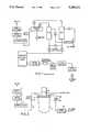
- FIG. 1depicts schematically a typical two-column adsorbent fractionating prior art system commercially available.
- FIG. 2is a schematic representation of one embodiment of the entire fluid fractionator respiratory support system of the instant invention.
- FIG. 3is a side elevation view of the apparatus which is the subject of FIG. 2.
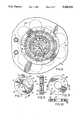
- FIG. 4is a view taken on line 4--4 of FIG. 3.
- FIG. 5is an enlarged sectional view taken on line 5--5 of FIG. 4.
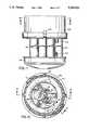
- FIG. 6is a sectional view taken on line 6--6 of FIG. 5.
- FIG. 7is a top plan view, partially cut away, of the rotor shoe, of the embodiment depicted in FIG. 2;
- FIG. 8is a sectional view taken on line 8--8 of FIG. 7;
- FIG. 9is a top plan view of the port plate of the embodiment depicted in FIG. 2;
- FIG. 10is a sectional view taken on line 10--10 of FIG. 9;
- FIG. 11is a side elevational view of an alternative configuration of the unit.
- FIG. 12is a sectional view taken on line 12--12 of FIG. 11;
- FIG. 13is an enlarged sectional view taken on line 13--13 of FIG. 12;
- FIG. 14is a sectional view taken on line 14--14 of FIG. 13;
- FIG. 15is an underside View of the rotor shoe as taken on line 15--15 of FIG. 13;
- FIG. 16is a sectional view taken on line 16--16 of FIG. 15;
- FIG. 17is an enlarged sectional view taken on line 17--17 of FIG. 12.
- FIG. 1depicts schematically a typical small two-column oxygen concentrator commercially available for patient use. It can readily be seen from the schematic diagram that a typical medical oxygen concentrator is a complex machine, with a multitude of interconnected and interacting parts. Attendant with this manifold complexity is the prospect of decreased reliability, or the increased chance that some component will fail, rendering the entire apparatus incapable of performing its life-supporting function.
- FIG. 2ambient air is drawn in through a pair of filters, one dust 1 and one high efficiency particle arrestor (HEPA) 2 connected in series, by a compressor 3. The air is compressed and forced within a conduit 4 into a heat exchanger 5.
- HEPAhigh efficiency particle arrestor
- the heat exchangerremoves most of the heat of compression before the air is fed into the inlet port 6 of the fluid fractionator.
- the cooling air in the exchangeris provided by a fan mounted on the compressor shaft, thereby, obviating the requirement of an additional motor and energy source.
- the fluid fractionatorin FIG. 3, comprises a product holding tank 9 containing a cluster or array of adsorber columns within its housing, a rotary valve distributor 10 and a gear motor 11 having a drive shaft 13.
- FIG. 4a view taken on line 4--4 of FIG. 3, shows the arrangement of an array of columns 22 within the holding tank relative to the inlet 6, outlet 7 and exhaust 8 ports of the rotary distributor valve assembly, which is affixed to the holding tank by means of a clamp band 12. Twelve columns are shown in this case but there could be any number of two or more.
- the rotary distributor valve depicted in FIG. 5, which is an enlarged sectional view taken on line 5--5 of FIG. 4,comprises a ported and channelled two-piece manifold 14 and a rotor 16 with a ported rotor shoe 18 and a cover plate 46, the rotor 16 being driven by a gear motor 11 (FIG. 3) at about two revolutions per minute, with the rotor 16 turning in circumferential ball bearing unit 17.
- Conical disk or Belleville spring 35urges cover plate 46 and rotor shoe 18 downward to secure them in position.
- the rotor 16 and its associated componentsare enclosed by cover 21, which is attached to manifold 14.
- the two-piece manifold 14contains a top section 15 which is ported and channeled to take in a stream of fluid through the inlet port 6 and channel it through an air feed passage 33 into a centrally located inlet port 19 in the rotor shoe 18, and subsequently to channel the fluid mixture exiting the rotor shoe radially from a circular array of inlet ports located in the port plate 20 towards each column 22 of an array of columns arranged about the center of the manifold.
- Each of these columnscontains a bed of adsorbent material 24 (zeolite in this case) which is selective for a particular molecular species of fluid or contaminant.
- the packed bedis held in place by a plate 26 at the bottom which is supported by spring 25, and perforated plates 27 at top and bottom with a spring 28 at the top.
- the bottom platehas a pressure-dropping means such as a small orifice 60, the diameter of which is empirically determined, at the center of each column.
- the bottom half of the manifoldwhich is also an upper column header plate 30, affixed to the top half of the manifold by means of a clamp band 12, acts as a cover for the channels and has the array of columns attached to its underside.
- the channels in the manifoldare sealed by a gasket or sealing compound.
- the port plate 20Recessed into the top of the manifold, coaxial to the exit port of the air feed channel 33, sealed and immobilized by means of a slot and key, is the port plate 20 which contains a number of holes in an equally spaced circular pattern, equal in number and aligned with the circular distribution of entry ports of channels to individual columns in the manifold.
- the manifoldhas a groove machined into its upper surface, just inside the port plate, which contains an air inlet rotary seal 32.
- the port plateis made from a suitable hardened material.
- the other major component of the rotary distributor valveis a gear motor-driven rotor 16 containing a ported rotor shoe 18, which slides over the rotor plate (FIGS. 5, 6, 7, and 8 all depict various aspects of the rotor/shoe).
- the rotor shoeis made from material known in the art to be suitable for use with the hardened material comprising the port plate, and is held in position over the rotor plate by spring-loaded or pressure compensated means. Shown is a conical or Belleville pressure compensating spring to counteract supply pressure. An arrangement of small coil springs can also be utilized for this purpose.
- FIG. 6a sectional view taken on line 6--6 of FIG. 5, shows the relationship of the arcuate air feed port or slot 36 of the rotor shoe 18 and the receiving ports 38 in the port plate, as well as the air feed channels 31 to each of the columns 22.
- the wide exhaust port 40collects refluxed fluid impurities desorbing and exiting from the columns, and channels them out through an exhaust outlet 8 (FIG. 5), through a "silencer" and into the atmosphere.
- FIG. 7is a top plan view, partially cut away, of the rotor shoe. Several other features come into view here.
- the desorbed columnsare vented upward through the exhaust slot 40, through a vent 42 in the rotor shoe cover plate 46, into the rotor void space, and out through the exhaust port 8 (FIG. 5).
- the third channelis a cross-port channel 44 which serves as a conduit between two columns which are in transition between the pressurizing and desorbing phases of a cycle. Its purpose is to quickly equalize pressure in columns transitioning between the adsorbing and desorbing cycles. This feature enhances product concentration at high product flow rates.
- the purge flow rateis the rate at which the purging fluid flows countercurrent to adsorption during regeneration of the columns. There is an optimal purge rate for maximal removal of nitrogen during regeneration.
- a very high purge ratecauses the pressure within a bed to be greater than atmospheric, resulting in reduced desorption efficiency.
- the cross-porting channel in the rotor shoeallows a pressure drop in the column bed before it enters the desorption cycle. This prevents a very rapid decompression and thus excessively high initial purge flow. This effect is easily measurable by simple instrumentation; however, its basis at the molecular level is not understood.
- FIG. 8is a sectional view taken on line 8--8 of FIG. 7, showing the routing of the pressurizing 34, cross-porting 44 and exhausting 40 channels in the rotor shoe 18.
- FIG. 9is a top plan view of the port plate showing the circular location of ports of channels leading to each of the array of columns
- FIG. 10is a sectional view taken on line 10--10 of FIG. 9.
- FIG. 11depicts an alternative embodiment of the apparatus of this invention, with a sectional view taken on line 12--12 thereof shown in FIG. 12.
- This latter viewshows an array of adsorber columns similar to the columns 22 depicted in FIG. 4.
- twelve columnsare the preferred number shown in the embodiment of FIG. 12, but there could be any number of two or more.
- a length to diameter ratio of greater than 6:1 for the adsorber columnsis preferred with the only limit on length being a practical one. This ratio permits the adsorption medium to be retained within the columns without the use of springs to compress and retain the adsorption media therein.
- At least one layer of filter mediamust, however, be present at each end of the column to avoid loss of adsorption medium through the inlet and outlet orifices to and from the columns.
- a cap 165will be mechanically seated over the distal end of each of said columns, through which outlet orifice (not shown) to product tank 130 (FIG. 13) extends.
- the rotary distributor valve depicted in FIG. 13,which is an enlarged sectional view taken on line 13--13 of FIG. 12, comprises a manifold 70 which is formed from one or more layers of aluminum, which layer or layers are pierced, and/or die formed or embossed and then, if a multiplicity of layers is used, sealed in a stacked configuration (by lamination or equivalent means) to form fluid channels.
- a manifold 70which is formed from one or more layers of aluminum, which layer or layers are pierced, and/or die formed or embossed and then, if a multiplicity of layers is used, sealed in a stacked configuration (by lamination or equivalent means) to form fluid channels.
- Four layers of aluminum (74, 75, 76 and 77)are shown in FIG. 13; it will be appreciated, however, that one or more layers of any lightweight, rigid, low density material (such as a-b-s resin plastic) may be used.
- the rotary valvefurther comprises a rotor shaft 80 rotatably retained within bearing housing 81 via flanged bearing 82 and within rotor shoe 85. Rotation of rotor shaft 80 is permitted by the presence of O-ring 92 around its circumference. Rotor shaft 80 is driven by gear motor 90 via motor shaft 135 at about one revolution per minute. As depicted in FIG. 13, said rotor shaft 80 is concentrically shaped above line 91 and eccentrically shaped below line 91. The eccentric shape is achieved by enlarging the lateral thickness of side wall 80A of rotor shaft 80 with respect to side wall 80B.
- Rotor shoe 85comprises a ported disc (similar in structure and composition to rotor shoe 18 depicted in FIG. 7) with raised side walls 86 and 87 which define a circular chamber into which rotor shaft 80 is seated.
- Rotor shoe 85is driven by torque exerted by rotor shaft 80 when the latter is driven by gear motor 90.
- Compression spring 93assists in sealing the shaft and shoe, thus maintaining the seal even when the apparatus is not in operation and compensating for wear experienced by the shaft and shoe.
- Use of this configuration to form a pressure balanced sealrequires less torque to turn the rotor, and thus less energy to operate the system than required by prior art systems or the embodiment of FIGS. 3-10.
- the pressure balanced seal between the rotor shaft and shoeis a function of the integrated pressure exerted on the surface of the rotor shoe between it and the rotor shaft during operation of the apparatus and the diameter of the rotor shaft.
- the fluid pressure at fluid inlet port 109 at the start of adsorption multiplied by the diameter squared of the rotor shaft (below line 91) and by ⁇ /4is equal to the force exerted to form a seal between the shaft and shoe.
- the shaft and shoewill remain sealed and balanced with respect to each other even if the fluid pressure at fluid inlet port 109 varies.
- there is a passage (not shown) from port 109 through to the interface surface between rotor shaft 80 and rotor shoe 85which serves to pressurize the interface to help maintain the pressure balanced seal.
- said noise control designcomprises muffler housing 100, having inner and outer surfaces preferably formed by a flexible plastic, which snaps over manifold 70 to form a cover for the manifold and rotary valve distributor.
- the noise control designfurther consists of pieces of acoustical foam or equivalent acoustical attenuating material placed within the apparatus as follows: at 101, said foam conforms topographically, in one or more pieces, to the inner surface of muffler housing 100. At 102, acoustical foam is seated vertically between bearing housing 81 and manifold 70. Said foam 102 may be retained in place by a portion of layer 74 of manifold 70 formed to provide a stop 103 between foam 102 and port plate 105.
- Port plate 105is similar in structure to port plate 20 of the embodiment depicted in FIG. 5, except that, while the inlet ports therein to the adsorber columns (one port per column) may be of any shape, they are preferably in the shape of wedges and most preferably in an arched keystone shape which will circumscribe the orifices 160 leading into the columns 115 via air fed channels 116 and ports 72 (FIG. 14). Wedge-shaped inlet ports are best depicted at 106 of FIG. 14, which is a sectional view taken on line 14--14 of FIG. 13.
- fluidis directed to the inlet ports 106 in port plate 105 for passage to the adsorber columns via channels in the rotor shoe.
- rotor shoe 85comprises three sets of channels.
- the first set of channelsconsist of pressurizing channels 110A and 110B which extend respectively and radially from central fluid inlet port 109 to symmetrical air feed ports 111 and 112 (while two air feed ports are shown, it will be appreciated that more than any number of two or more may be used as long as the ports are arranged in axial symmetry about inlet port 109).
- fluidtravels through fluid inlet port 109 to air feed ports 111 and 112 through ports 106 in port plate 105 to air feed channels 116 (shown in FIG. 14) Which lead from each port 106 via ports 72 and 160 to an adsorber column (shown in sectional view in FIG. 14 at 115).
- the second set of channelsconsist of at least two exhaust ports (113 and 114 in FIG. 15) which will be equal in number to air feed ports 111 and 112 and will also be arranged with axial symmetry with respect to inlet port 109.
- the desorbed columnsare vented upward through exhaust ports 113 and 114, to annular air space 150 and eventually to the atmosphere via slots 107 in muffler housing 100 (FIG. 13).
- the third set of channelsare at least one pair of symmetrical cross-port channels 118 and 119 (equal in number to air feed ports 111 and 112). These channels serve to quickly equalize pressure between columns transitioning between the adsorption and desorption phases much in the same manner as does the single cross-port channel 44 depicted in FIG. 7.
- the number and symmetry of shape and size common to each set of channelsavoids the preloading spring which results from the use of asymmetrical ports, where variances between the fluid pressure present at the air feed and exhausts ports may push the rotor shoe against the port plate during operation.
- FIGS. 11-17is substantially similar to the apparatus of FIGS. 3-10.
- the method of fractionationis as follows: compressed air enters the inlet port 6 of the manifold (FIG. 6) and is channeled through the air passage in the manifold 33 communicating with the rotor shoe 18 and then into the arcuate pressurizing slot 36 to enter sequentially into several ports 38 in the port plate as the rotor shoe 18 turns. As these ports become pressurized, the gas mixture enters, pressurizes and flows through each attached column 22 where the separation takes place.
- the desired gas, oxygen in this caseis free to move through the zeolite adsorbent bed 24 (e.g., similar to that provided by the molecular sieve division of UOP), while the undesired gases and vapor (nitrogen plus CO 2 , CO, H 2 O) are retained, because of their molecular size and the relatively high pressure and low temperature, in the matrix of the adsorbent bed.
- the undesired gases and vapornitrogen plus CO 2 , CO, H 2 O
- the purified desired gas productmoves out of the column through a pressure-dropping means such as a small orifice 60 or a fluid porous plug in the bottom of the column and into the circumscribed product tank 9.
- a pressure-dropping meanssuch as a small orifice 60 or a fluid porous plug in the bottom of the column and into the circumscribed product tank 9.
- a relatively small portion of the oxygenis tapped off by the distribution system conduit at the outlet port 7 (FIG. 6) for use by the patient, and another, relatively large, portion enters the columns in the opposite bank, which are under nearly atmospheric pressure, through corresponding small pressure dropping/flow restricting orifices in the bottom to reflux through the bed in a direction opposite to gas flow during pressurization.
- the amount of product used to purge versus the amount delivered by the distribution systemcan vary, depending on the degree of product purity desired.
- This backwash of product gas at pressure lower than the adsorbing cycleremoves the contaminant embedded in the zeolite matrix, in this case nitrogen, and flushes it out through the top of each column into the manifold 14, the port plate 20 and through the rotor shoe 18 and exhaust outlet 8 into the atmosphere via a silencer or muffler.
- the tapped oxygen-rich product gasthen moves within a dispensing conduit 46 through a manually controlled valve 50 with a flow meter, through a final filter (HEPA) 52 and to the dispensing terminus.
- HEPAfinal filter
- the method of fractionationis as follows: compressed air enters the manifold from inlet conduit 120 through inlet port 121 (FIGS. 14 and 17) and is channeled through channel 71 communicating with the rotor shoe 85 via central fluid inlet port 109. The air then passes through radial channels 110A and 110B to inlet ports 111 and 112. As the rotor shoe turns over port plate 105, inlet ports 111 and 112 will each become aligned with an equal plurality of wedge-shaped ports 106, thus allowing the air to enter the columns 115 via air feed channels 116 corresponding with each plurality of ports 106 served respectively by inlet ports 111 and 112. Adsorption occurs within the columns as described above.
- product tank 130differs from product tank 9 (FIG. 5) in that tank 130 is smaller in volume and does not surround columns 115 except at their distal ends; i.e., opposite manifold 70.
- This smaller product tank(vis-a-vis product tank 130 [FIG. 11]) reduces the overall weight of the system.
- the limits on reduction of the size of product tank 130are practical ones, principally dictated by storage needs and the volume required to regulate the output pressure of the system sufficiently well to reduce the need for a pressure regulator.
- Productis tapped for use by the operator or patient via outlet conduit 125.
- the systemis then purged as described above with respect to the method used with the apparatus depicted in FIGS. 3-10.
- the cycle profileis such that each column is pressurized for approximately 12.5 seconds, equilibrated for 2.5 seconds, and desorbed for 12.5 seconds and re-equilibrated.
- This profile of the cycleis obtainable only when the intake and exhaust slots in the rotor shoe are equal in size, and service an equal number of columns.
- the profilecan be altered as desired by varying the size of the respective inlet and exhaust ports. This is a desirable feature which cannot be put into effect in any of the prior art mechanisms.
- This cycleis sequentially and continuously established for each column.
- This mode of operationproduces a relatively constant flow of product, improving with a greater number of columns, eliminating the need for a pressure reducing regulator.
- the average product outlet pressureis nearly constant and about twice the regulated delivery pressure of prior art fractionators.
- the column lengthmay be short, even with a large length:diameter ratio which is essential for effective adsorption separation.
- the large number of columns and the rotary distributor valveresult in a quasi steady-state gas flow through the compressor and other components which produces a number of advantages and system simplifications.
- the inventionpermits optimization of the adsorption cycle by providing the possibility of employing unequal times for the adsorption and desorption phases of the cycle.
- Prior art two chamber systemsare inherently bound to equal times.
- Another notable advantage of the inventionis the elimination of many components which are necessary in the prior art, thereby, reducing size, weight and the amount of maintenance, concomitantly increasing reliability and maneuverability for the ambulatory patient. These eliminated components include:
- adsorbent material utilized in this embodimentis a synthetic zeolite
- this inventionshould not be construed as restricted to its use. It is understood by those well versed in the art that many other configurations are possible while employing the rotary distributor concept, which are within the spirit and scope of this invention.
Landscapes
- Chemical & Material Sciences (AREA)
- Engineering & Computer Science (AREA)
- Analytical Chemistry (AREA)
- General Chemical & Material Sciences (AREA)
- Oil, Petroleum & Natural Gas (AREA)
- Chemical Kinetics & Catalysis (AREA)
- Separation Of Gases By Adsorption (AREA)
Abstract
Description
Claims (41)
Priority Applications (2)
| Application Number | Priority Date | Filing Date | Title |
|---|---|---|---|
| US07/835,918US5268021A (en) | 1989-11-20 | 1992-02-28 | Fluid fractionator |
| US08/142,614US5366541A (en) | 1989-11-20 | 1993-10-25 | Fluid fractionator |
Applications Claiming Priority (4)
| Application Number | Priority Date | Filing Date | Title |
|---|---|---|---|
| US43878689A | 1989-11-20 | 1989-11-20 | |
| US07/660,177US5112367A (en) | 1989-11-20 | 1991-02-25 | Fluid fractionator |
| US07/835,918US5268021A (en) | 1989-11-20 | 1992-02-28 | Fluid fractionator |
| CA002130824ACA2130824C (en) | 1989-11-20 | 1992-02-28 | Fluid fractionator |
Related Parent Applications (1)
| Application Number | Title | Priority Date | Filing Date |
|---|---|---|---|
| US07/660,177Continuation-In-PartUS5112367A (en) | 1989-11-20 | 1991-02-25 | Fluid fractionator |
Related Child Applications (1)
| Application Number | Title | Priority Date | Filing Date |
|---|---|---|---|
| US08/142,614ContinuationUS5366541A (en) | 1989-11-20 | 1993-10-25 | Fluid fractionator |
Publications (1)
| Publication Number | Publication Date |
|---|---|
| US5268021Atrue US5268021A (en) | 1993-12-07 |
Family
ID=27427170
Family Applications (2)
| Application Number | Title | Priority Date | Filing Date |
|---|---|---|---|
| US07/835,918Expired - LifetimeUS5268021A (en) | 1989-11-20 | 1992-02-28 | Fluid fractionator |
| US08/142,614Expired - LifetimeUS5366541A (en) | 1989-11-20 | 1993-10-25 | Fluid fractionator |
Family Applications After (1)
| Application Number | Title | Priority Date | Filing Date |
|---|---|---|---|
| US08/142,614Expired - LifetimeUS5366541A (en) | 1989-11-20 | 1993-10-25 | Fluid fractionator |
Country Status (1)
| Country | Link |
|---|---|
| US (2) | US5268021A (en) |
Cited By (66)
| Publication number | Priority date | Publication date | Assignee | Title |
|---|---|---|---|---|
| US5366541A (en)* | 1989-11-20 | 1994-11-22 | Dynotec Corporation | Fluid fractionator |
| US5487775A (en)* | 1994-05-09 | 1996-01-30 | The Boc Group, Inc. | Continuous pressure difference driven adsorption process |
| US5578115A (en)* | 1995-07-24 | 1996-11-26 | Devilbiss Health Care, Inc. | Molecular sieve container for oxygen concentrator |
| US5593478A (en)* | 1994-09-28 | 1997-01-14 | Sequal Technologies, Inc. | Fluid fractionator |
| US5681376A (en)* | 1995-11-07 | 1997-10-28 | Calgon Carbon Corporation | Rotating flow distributor assembly for use in continuously distributing decontamination and regeneration fluid flow |
| EP0832679A3 (en)* | 1996-09-27 | 1998-04-29 | The Boc Group, Inc. | Process and apparatus for gas separation |
| US5807423A (en)* | 1996-09-27 | 1998-09-15 | The Boc Group, Inc. | Process and apparatus for gas separation |
| US5814131A (en)* | 1996-09-27 | 1998-09-29 | The Boc Group, Inc. | Process and apparatus for gas separation |
| US5814130A (en)* | 1996-09-27 | 1998-09-29 | The Boc Group, Inc. | Process and apparatus for gas separation |
| US5820656A (en)* | 1997-01-21 | 1998-10-13 | The Boc Group, Inc. | Process and apparatus for gas separation |
| US5827358A (en)* | 1996-11-08 | 1998-10-27 | Impact Mst, Incorporation | Rapid cycle pressure swing adsorption oxygen concentration method and apparatus |
| EP0853967A3 (en)* | 1997-01-21 | 1998-11-04 | The Boc Group, Inc. | Valve apparatus for gas separation and adsorption system |
| US5891217A (en)* | 1997-01-21 | 1999-04-06 | The Boc Group, Inc. | Process and apparatus for gas separation |
| US5979440A (en)* | 1997-06-16 | 1999-11-09 | Sequal Technologies, Inc. | Methods and apparatus to generate liquid ambulatory oxygen from an oxygen concentrator |
| US5997617A (en)* | 1997-01-31 | 1999-12-07 | Healthdyne Technologies, Inc. | Pressure swing absorption system with multi-chamber canister |
| US6056804A (en)* | 1997-06-30 | 2000-05-02 | Questor Industries Inc. | High frequency rotary pressure swing adsorption apparatus |
| US6063161A (en)* | 1996-04-24 | 2000-05-16 | Sofinoy Societte Financiere D'innovation Inc. | Flow regulated pressure swing adsorption system |
| US6311719B1 (en) | 1999-08-10 | 2001-11-06 | Sequal Technologies, Inc. | Rotary valve assembly for pressure swing adsorption system |
| US6471744B1 (en) | 2001-08-16 | 2002-10-29 | Sequal Technologies, Inc. | Vacuum-pressure swing absorption fractionator and method of using the same |
| US20030005928A1 (en)* | 2000-08-03 | 2003-01-09 | Sequal Technologies, Inc. | Portable oxygen concentration system and method of using the same |
| US20030084789A1 (en)* | 2001-10-22 | 2003-05-08 | Min Jung Kim | Concentrating chamber in oxygen concentrating apparatus |
| US6629525B2 (en) | 2000-08-03 | 2003-10-07 | Sequal Technologies, Inc. | Portable oxygen concentration system and method of using the same |
| US20040007056A1 (en)* | 2001-08-06 | 2004-01-15 | Webb Cynthia C. | Method for testing catalytic converter durability |
| USRE38493E1 (en)* | 1996-04-24 | 2004-04-13 | Questair Technologies Inc. | Flow regulated pressure swing adsorption system |
| US20040179998A1 (en)* | 2003-03-14 | 2004-09-16 | Gittleman Craig S. | Fuel processor module for hydrogen production for a fuel cell engine using pressure swing adsorption |
| US20040199746A1 (en)* | 1992-12-31 | 2004-10-07 | Seiko Epson Corporation | System and method for assigning tags to control instruction processing in a superscalar processor |
| US20040197616A1 (en)* | 2003-04-01 | 2004-10-07 | Edlund David J. | Oxidant-enriched fuel cell system |
| US20050005771A1 (en)* | 2003-07-09 | 2005-01-13 | H2Gen Innovations, Inc. | Modular pressure swing adsorption process and apparatus |
| US20050056149A1 (en)* | 2003-09-17 | 2005-03-17 | Metso Automation Usa Inc. | System and method for treating fluid using a multi-port valve assembly |
| US20060130651A1 (en)* | 2004-12-22 | 2006-06-22 | Bizjak Travis A | Systems and methods for regulating heating assembly operation through pressure swing adsorption purge control |
| US20060130650A1 (en)* | 2004-12-20 | 2006-06-22 | Givens James A | Temperature-based breakthrough detection and pressure swing adsorption systems and fuel processing systems including the same |
| US7066985B2 (en) | 2003-10-07 | 2006-06-27 | Inogen, Inc. | Portable gas fractionalization system |
| US20060230931A1 (en)* | 2005-04-05 | 2006-10-19 | Bliss Peter L | Portable oxygen concentrator |
| US20060230929A1 (en)* | 2005-04-05 | 2006-10-19 | Bliss Peter L | Portable oxygen concentrator |
| US20060230939A1 (en)* | 2005-04-05 | 2006-10-19 | Bliss Peter L | Portable oxygen concentrator |
| US7135059B2 (en) | 2003-10-07 | 2006-11-14 | Inogen, Inc. | Portable gas fractionalization system |
| US20070119456A1 (en)* | 2005-11-29 | 2007-05-31 | Scott Mark H | Hypoxic gas stream system and method of use |
| US20070289445A1 (en)* | 2006-06-15 | 2007-12-20 | Mei Hua | Compact and efficient pressure swing oxygen concentrator |
| US20080148935A1 (en)* | 2004-12-20 | 2008-06-26 | Idatech, Llc | Temperature-based breakthrough detection and pressure swing adsorption systems and fuel processing systems including the same |
| US7438745B2 (en) | 2003-10-07 | 2008-10-21 | Inogen, Inc. | Portable gas fractionalization system |
| US20090025560A1 (en)* | 2005-04-15 | 2009-01-29 | Teijin Pharma Limited | Oxygen Concentrator |
| US20090065007A1 (en)* | 2007-09-06 | 2009-03-12 | Wilkinson William R | Oxygen concentrator apparatus and method |
| WO2008051606A3 (en)* | 2006-10-27 | 2009-07-09 | Questair Technologies Inc | Compact pressure swing reformer |
| EP2098277A1 (en)* | 2008-02-20 | 2009-09-09 | Delphi Technologies, Inc. | Single manifold assembly for oxygen-generating systems |
| USD606655S1 (en) | 2008-06-27 | 2009-12-22 | Inova Labs, Llc | Portable oxygen concentrator |
| US7686870B1 (en) | 2005-12-29 | 2010-03-30 | Inogen, Inc. | Expandable product rate portable gas fractionalization system |
| US7837765B2 (en) | 2007-12-12 | 2010-11-23 | Idatech, Llc | Systems and methods for supplying auxiliary fuel streams during intermittent byproduct discharge from pressure swing adsorption assemblies |
| US7922789B1 (en) | 2003-10-07 | 2011-04-12 | Inogen, Inc. | Portable gas fractionalization system |
| US20110197890A1 (en)* | 2005-02-09 | 2011-08-18 | Vbox, Incorporated | Ambulatory oxygen concentrator |
| US20110247620A1 (en)* | 2010-04-07 | 2011-10-13 | Chart Sequal Technologies Inc. | Portable Oxygen Delivery Device |
| US8070841B2 (en) | 2007-12-12 | 2011-12-06 | Idatech, Llc | Systems and methods for supplying auxiliary fuel streams during intermittent byproduct discharge from pressure swing adsorption assemblies |
| US8210205B2 (en) | 2006-03-09 | 2012-07-03 | Michaels Gregory A | Rotary valve assembly |
| US8394178B2 (en) | 2009-07-22 | 2013-03-12 | Vbox, Incorporated | Apparatus for separating oxygen from ambient air |
| US8603228B2 (en) | 2010-09-07 | 2013-12-10 | Inova Labs, Inc. | Power management systems and methods for use in an oxygen concentrator |
| US8616207B2 (en) | 2010-09-07 | 2013-12-31 | Inova Labs, Inc. | Oxygen concentrator heat management system and method |
| US20140060326A1 (en)* | 2012-09-04 | 2014-03-06 | Exxonmobil Research And Engineering Company | Increasing scales, capacities, and/or efficiencies in swing adsorption processes with hydrocarbon gas feeds |
| US20140076164A1 (en)* | 2011-05-09 | 2014-03-20 | L'Air Liquide Société Anonyme pour I'Exploitation des Procédés Georges Claude | Adsorption purification unit with rotary distributor and means for regulating the flow rates |
| US9440180B2 (en) | 2012-10-12 | 2016-09-13 | Inova Labs, Llc | Oxygen concentrator systems and methods |
| US9440036B2 (en) | 2012-10-12 | 2016-09-13 | InovaLabs, LLC | Method and systems for the delivery of oxygen enriched gas |
| US9440179B2 (en) | 2014-02-14 | 2016-09-13 | InovaLabs, LLC | Oxygen concentrator pump systems and methods |
| US9717876B2 (en) | 2012-10-12 | 2017-08-01 | Inova Labs, Inc. | Dual oxygen concentrator systems and methods |
| US10047869B2 (en) | 2012-08-22 | 2018-08-14 | Ge Healthcare Bio-Sciences Ab | Versatile rotary valve |
| WO2020117871A1 (en)* | 2018-12-03 | 2020-06-11 | Avox Systems Inc. | Locking manifold for chemical oxygen generator |
| US20220001324A1 (en)* | 2018-09-29 | 2022-01-06 | Bluegeneration, S.L. | Installation and method for recovering gaseous substances from gas flows |
| US11458274B2 (en) | 2016-05-03 | 2022-10-04 | Inova Labs, Inc. | Method and systems for the delivery of oxygen enriched gas |
| US20230003316A1 (en)* | 2021-07-02 | 2023-01-05 | Artisan Industries Inc. | Vision System for Rotary Valve |
Families Citing this family (23)
| Publication number | Priority date | Publication date | Assignee | Title |
|---|---|---|---|---|
| US6152163A (en)* | 1998-04-23 | 2000-11-28 | United Dominion Industries, Inc. | Switching valve for multi-chamber adsorbent air and gas fractionation system |
| US6143056A (en)* | 1998-11-19 | 2000-11-07 | Praxair Technology, Inc. | Rotary valve for two bed vacuum pressure swing absorption system |
| US7250073B2 (en)* | 1999-12-09 | 2007-07-31 | Questair Technologies, Inc. | Life support oxygen concentrator |
| US6514319B2 (en)* | 1999-12-09 | 2003-02-04 | Questair Technologies Inc. | Life support oxygen concentrator |
| US6551384B1 (en) | 2001-07-05 | 2003-04-22 | Praxair Technology, Inc. | Medical oxygen concentrator |
| EP1481703A4 (en)* | 2002-03-05 | 2011-02-02 | Teijin Ltd | Oxygen enricher |
| EP1585940A4 (en)* | 2002-03-19 | 2009-09-02 | Automotive Systems Lab | Vehicle rollover detection system |
| US6889710B2 (en)* | 2002-11-15 | 2005-05-10 | Air Products And Chemicals, Inc. | Rotary sequencing valve with flexible port plate |
| FR2855433B1 (en)* | 2003-06-02 | 2007-01-12 | Air Liquide | GAS GENERATOR ASSEMBLY |
| WO2005025722A1 (en)* | 2003-09-09 | 2005-03-24 | Teijin Pharma Limited | Oxygen concentrating apparatus and rotary valve |
| US20050098034A1 (en)* | 2003-11-12 | 2005-05-12 | Gittleman Craig S. | Hydrogen purification process using pressure swing adsorption for fuel cell applications |
| US7011693B2 (en)* | 2003-11-12 | 2006-03-14 | General Motors Corporation | Control of a hydrogen purifying pressure swing adsorption unit in fuel processor module for hydrogen generation |
| US8020553B2 (en)* | 2005-02-09 | 2011-09-20 | Vbox, Incorporated | Ambulatory oxygen concentrator containing a three phase vacuum separation system |
| US20060174875A1 (en)* | 2005-02-09 | 2006-08-10 | Vbox, Incorporated | Ambulatory oxygen concentrator containing a power pack |
| US7604005B2 (en) | 2005-02-09 | 2009-10-20 | Vbox Incorporated | Adsorbent cartridge for oxygen concentrator |
| US7766010B2 (en) | 2005-02-09 | 2010-08-03 | Vbox, Incorporated | Method of controlling the rate of oxygen produced by an oxygen concentrator |
| US7121276B2 (en)* | 2005-02-09 | 2006-10-17 | Vbox, Incorporated | Personal oxygen concentrator |
| US7431032B2 (en)* | 2005-02-09 | 2008-10-07 | Vbox Incorporated | Low power ambulatory oxygen concentrator |
| US7866315B2 (en) | 2005-02-09 | 2011-01-11 | Vbox, Incorporated | Method and apparatus for controlling the purity of oxygen produced by an oxygen concentrator |
| US7288189B2 (en)* | 2005-02-11 | 2007-10-30 | Bonifer Jeffery P | Multi-faceted intake filter for an aquarium |
| US7399347B2 (en)* | 2005-04-13 | 2008-07-15 | Shao-Shih Huang | Control valve structure for an oxygen machine |
| ITMI20120676A1 (en)* | 2012-04-24 | 2013-10-25 | Getters Spa | METHOD AND REGENERABLE PURIFICATION OF AMBIENT TEMPERATURE PURIFICATION FOR DIAZOTO MONOXIDE |
| FR3052085B1 (en)* | 2016-06-02 | 2020-12-25 | Air Liquide | AIR SEPARATION DEVICE AND GAS GENERATION DEVICE INCLUDING SUCH A DEVICE |
Citations (34)
| Publication number | Priority date | Publication date | Assignee | Title |
|---|---|---|---|---|
| DE737929C (en)* | 1938-12-04 | 1943-07-29 | Bamag Meguin Ag | Adsorption system for the recovery of solvents |
| US2759560A (en)* | 1953-03-02 | 1956-08-21 | Jefferson Lake Sulphur Co | Method of removing water vapor and recovering condensable hydrocarbons from natural gas under high pressure |
| GB784150A (en)* | 1954-11-24 | 1957-10-02 | Air Control Installations Ltd | Improvements in or relating to air drying apparatus |
| US2955673A (en)* | 1958-08-18 | 1960-10-11 | Kahn And Company Inc | Process and apparatus for dehydrating gas |
| US3069830A (en)* | 1960-03-24 | 1962-12-25 | Exxon Research Engineering Co | Heatless fractionator |
| US3104162A (en)* | 1960-05-18 | 1963-09-17 | Exxon Research Engineering Co | Timing cycle for improved heatless fractionation of gaseous materials |
| US3138439A (en)* | 1960-04-12 | 1964-06-23 | Exxon Research Engineering Co | Apparatus and process for heatless fractionation of gaseous constituents |
| US3182435A (en)* | 1960-04-29 | 1965-05-11 | Exxon Research Engineering Co | Apparatus for fractionation of gaseous mixtures |
| US3242650A (en)* | 1963-09-30 | 1966-03-29 | Exxon Research Engineering Co | Adsorption apparatus |
| US3323292A (en)* | 1964-12-01 | 1967-06-06 | Dielectric Products Engineerin | Apparatus for fractionating gaseous mixtures |
| US3464186A (en)* | 1967-02-10 | 1969-09-02 | Hankison Corp | Dryer for compressed fluid systems |
| US3472000A (en)* | 1968-04-29 | 1969-10-14 | Westinghouse Air Brake Co | Air dryer and purge control unit |
| US3487608A (en)* | 1966-03-11 | 1970-01-06 | Roderich W Graff | Method and apparatus for adsorption of molecules from fluids |
| US3572008A (en)* | 1968-10-25 | 1971-03-23 | Hankison Corp | Methods and means for cleaning and drying compressed fluid systems |
| US3880616A (en)* | 1973-11-19 | 1975-04-29 | Bendix Corp | Respiratory support system |
| US4038054A (en)* | 1972-03-25 | 1977-07-26 | Graeff Roderich Wilhelm | Adsorption apparatus |
| US4168149A (en)* | 1976-12-23 | 1979-09-18 | Boc Limited | Gas separation |
| JPS54136575A (en)* | 1978-04-14 | 1979-10-23 | Jidosha Kiki Co | Compressed air drying apparatus |
| US4209308A (en)* | 1972-09-25 | 1980-06-24 | Blodgett Gerry A | Sorption system |
| US4272265A (en)* | 1979-06-22 | 1981-06-09 | Essex Cryogenics Of Missouri, Inc. | Apparatus for pressure swing generation of oxygen |
| US4378982A (en)* | 1981-08-28 | 1983-04-05 | Greene & Kellogg, Inc. | Compact oxygen concentrator |
| US4428372A (en)* | 1980-07-31 | 1984-01-31 | Linde Aktiengesellschaft | Process and apparatus for providing breathing gas |
| US4469494A (en)* | 1983-01-31 | 1984-09-04 | Kinetics Technology International Corporation | Disc operated gas purification system |
| US4496376A (en)* | 1978-01-26 | 1985-01-29 | Litton Systems, Inc. | Variable area molecular sieve container having a thermal control system |
| US4648888A (en)* | 1982-07-09 | 1987-03-10 | Hudson Oxygen Therapy Sales Co. | Oxygen concentrator |
| US4713094A (en)* | 1985-08-28 | 1987-12-15 | Jidosha Kiki Co., Ltd. | Air drier apparatus |
| JPS6377516A (en)* | 1986-09-20 | 1988-04-07 | Tokico Ltd | gas separation equipment |
| US4787417A (en)* | 1987-11-24 | 1988-11-29 | Windsor Jr John F | Rotary pressure/purge valve |
| US4826510A (en)* | 1988-01-13 | 1989-05-02 | The John Bunn Company | Portable low profile DC oxygen concentrator |
| US4877429A (en)* | 1989-03-06 | 1989-10-31 | Hunter Donald W | Valve device for P.S.A. or R.P.S.A. systems |
| US4892569A (en)* | 1987-02-23 | 1990-01-09 | Nippon Air Brake Co., Ltd. | Compressed air pressure supply system |
| US4925464A (en)* | 1988-11-17 | 1990-05-15 | Ryder International Corporation | Fluid flow switching valve assembly and system |
| US5112367A (en)* | 1989-11-20 | 1992-05-12 | Hill Charles C | Fluid fractionator |
| US5114441A (en)* | 1990-11-02 | 1992-05-19 | Ryder International Corporation | Oxygen concentrator system and valve structure |
Family Cites Families (13)
| Publication number | Priority date | Publication date | Assignee | Title |
|---|---|---|---|---|
| US2586670A (en)* | 1945-01-31 | 1952-02-19 | Christian J Lambertsen | Selective gas adsorber |
| US2507028A (en)* | 1945-05-26 | 1950-05-09 | Niles Bement Pond Co | Dehumidifying device |
| US2593132A (en)* | 1947-12-05 | 1952-04-15 | Russell R Gannon | Container for desiccant material |
| US4194891A (en)* | 1978-12-27 | 1980-03-25 | Union Carbide Corporation | Multiple bed rapid pressure swing adsorption for oxygen |
| US4302224A (en)* | 1979-10-12 | 1981-11-24 | Greene & Kellogg, Inc. | Compact oxygen concentrator |
| US4349357A (en)* | 1980-06-23 | 1982-09-14 | Stanley Aviation Corporation | Apparatus and method for fractionating air and other gaseous mixtures |
| US4439213A (en)* | 1981-12-30 | 1984-03-27 | The C. M. Kemp Manufacturing Co. | Nitrogen generation system |
| US4440548A (en)* | 1982-04-19 | 1984-04-03 | Calgon Carbon Corporation | Pressure swing absorption system |
| US4584001A (en)* | 1983-08-09 | 1986-04-22 | Vbm Corporation | Modular oxygen generator |
| US4631073A (en)* | 1984-03-15 | 1986-12-23 | Wilkerson Corporation | Method and apparatus for theadsorptive fractionation of gases |
| US4880443A (en)* | 1988-12-22 | 1989-11-14 | The United States Of America As Represented By The Secretary Of The Air Force | Molecular sieve oxygen concentrator with secondary oxygen purifier |
| US5268021A (en)* | 1989-11-20 | 1993-12-07 | Dynotec Corporation | Fluid fractionator |
| EP0449448B1 (en)* | 1990-03-29 | 1997-01-22 | The Boc Group, Inc. | Process for producing oxygen enriched product stream |
- 1992
- 1992-02-28USUS07/835,918patent/US5268021A/ennot_activeExpired - Lifetime
- 1993
- 1993-10-25USUS08/142,614patent/US5366541A/ennot_activeExpired - Lifetime
Patent Citations (34)
| Publication number | Priority date | Publication date | Assignee | Title |
|---|---|---|---|---|
| DE737929C (en)* | 1938-12-04 | 1943-07-29 | Bamag Meguin Ag | Adsorption system for the recovery of solvents |
| US2759560A (en)* | 1953-03-02 | 1956-08-21 | Jefferson Lake Sulphur Co | Method of removing water vapor and recovering condensable hydrocarbons from natural gas under high pressure |
| GB784150A (en)* | 1954-11-24 | 1957-10-02 | Air Control Installations Ltd | Improvements in or relating to air drying apparatus |
| US2955673A (en)* | 1958-08-18 | 1960-10-11 | Kahn And Company Inc | Process and apparatus for dehydrating gas |
| US3069830A (en)* | 1960-03-24 | 1962-12-25 | Exxon Research Engineering Co | Heatless fractionator |
| US3138439A (en)* | 1960-04-12 | 1964-06-23 | Exxon Research Engineering Co | Apparatus and process for heatless fractionation of gaseous constituents |
| US3182435A (en)* | 1960-04-29 | 1965-05-11 | Exxon Research Engineering Co | Apparatus for fractionation of gaseous mixtures |
| US3104162A (en)* | 1960-05-18 | 1963-09-17 | Exxon Research Engineering Co | Timing cycle for improved heatless fractionation of gaseous materials |
| US3242650A (en)* | 1963-09-30 | 1966-03-29 | Exxon Research Engineering Co | Adsorption apparatus |
| US3323292A (en)* | 1964-12-01 | 1967-06-06 | Dielectric Products Engineerin | Apparatus for fractionating gaseous mixtures |
| US3487608A (en)* | 1966-03-11 | 1970-01-06 | Roderich W Graff | Method and apparatus for adsorption of molecules from fluids |
| US3464186A (en)* | 1967-02-10 | 1969-09-02 | Hankison Corp | Dryer for compressed fluid systems |
| US3472000A (en)* | 1968-04-29 | 1969-10-14 | Westinghouse Air Brake Co | Air dryer and purge control unit |
| US3572008A (en)* | 1968-10-25 | 1971-03-23 | Hankison Corp | Methods and means for cleaning and drying compressed fluid systems |
| US4038054A (en)* | 1972-03-25 | 1977-07-26 | Graeff Roderich Wilhelm | Adsorption apparatus |
| US4209308A (en)* | 1972-09-25 | 1980-06-24 | Blodgett Gerry A | Sorption system |
| US3880616A (en)* | 1973-11-19 | 1975-04-29 | Bendix Corp | Respiratory support system |
| US4168149A (en)* | 1976-12-23 | 1979-09-18 | Boc Limited | Gas separation |
| US4496376A (en)* | 1978-01-26 | 1985-01-29 | Litton Systems, Inc. | Variable area molecular sieve container having a thermal control system |
| JPS54136575A (en)* | 1978-04-14 | 1979-10-23 | Jidosha Kiki Co | Compressed air drying apparatus |
| US4272265A (en)* | 1979-06-22 | 1981-06-09 | Essex Cryogenics Of Missouri, Inc. | Apparatus for pressure swing generation of oxygen |
| US4428372A (en)* | 1980-07-31 | 1984-01-31 | Linde Aktiengesellschaft | Process and apparatus for providing breathing gas |
| US4378982A (en)* | 1981-08-28 | 1983-04-05 | Greene & Kellogg, Inc. | Compact oxygen concentrator |
| US4648888A (en)* | 1982-07-09 | 1987-03-10 | Hudson Oxygen Therapy Sales Co. | Oxygen concentrator |
| US4469494A (en)* | 1983-01-31 | 1984-09-04 | Kinetics Technology International Corporation | Disc operated gas purification system |
| US4713094A (en)* | 1985-08-28 | 1987-12-15 | Jidosha Kiki Co., Ltd. | Air drier apparatus |
| JPS6377516A (en)* | 1986-09-20 | 1988-04-07 | Tokico Ltd | gas separation equipment |
| US4892569A (en)* | 1987-02-23 | 1990-01-09 | Nippon Air Brake Co., Ltd. | Compressed air pressure supply system |
| US4787417A (en)* | 1987-11-24 | 1988-11-29 | Windsor Jr John F | Rotary pressure/purge valve |
| US4826510A (en)* | 1988-01-13 | 1989-05-02 | The John Bunn Company | Portable low profile DC oxygen concentrator |
| US4925464A (en)* | 1988-11-17 | 1990-05-15 | Ryder International Corporation | Fluid flow switching valve assembly and system |
| US4877429A (en)* | 1989-03-06 | 1989-10-31 | Hunter Donald W | Valve device for P.S.A. or R.P.S.A. systems |
| US5112367A (en)* | 1989-11-20 | 1992-05-12 | Hill Charles C | Fluid fractionator |
| US5114441A (en)* | 1990-11-02 | 1992-05-19 | Ryder International Corporation | Oxygen concentrator system and valve structure |
Non-Patent Citations (6)
| Title |
|---|
| Breck et al., Chem. Engrg. Prog. pp. 43 53 (Oct. 1977).* |
| Breck et al., Chem. Engrg. Prog. pp. 43-53 (Oct. 1977). |
| Lukchus "Adsorption Systems" Linde Bulletin F-4164, reprinted from Chem. Engrg. (Jun. 11; Jul. 9 and May 6, 1973). |
| Lukchus Adsorption Systems Linde Bulletin F 4164, reprinted from Chem. Engrg. (Jun. 11; Jul. 9 and May 6, 1973).* |
| Nemmies Compressed Air, pp. 11 14 (Sep. 1959).* |
| Nemmies Compressed Air, pp. 11-14 (Sep. 1959). |
Cited By (130)
| Publication number | Priority date | Publication date | Assignee | Title |
|---|---|---|---|---|
| US5366541A (en)* | 1989-11-20 | 1994-11-22 | Dynotec Corporation | Fluid fractionator |
| US20040199746A1 (en)* | 1992-12-31 | 2004-10-07 | Seiko Epson Corporation | System and method for assigning tags to control instruction processing in a superscalar processor |
| US5487775A (en)* | 1994-05-09 | 1996-01-30 | The Boc Group, Inc. | Continuous pressure difference driven adsorption process |
| US5593478A (en)* | 1994-09-28 | 1997-01-14 | Sequal Technologies, Inc. | Fluid fractionator |
| US5578115A (en)* | 1995-07-24 | 1996-11-26 | Devilbiss Health Care, Inc. | Molecular sieve container for oxygen concentrator |
| US5681376A (en)* | 1995-11-07 | 1997-10-28 | Calgon Carbon Corporation | Rotating flow distributor assembly for use in continuously distributing decontamination and regeneration fluid flow |
| EP2275191A1 (en) | 1996-04-24 | 2011-01-19 | Xebec Adsorption Inc. | Flow Regulated Pressure Swing Adsorption System |
| USRE38493E1 (en)* | 1996-04-24 | 2004-04-13 | Questair Technologies Inc. | Flow regulated pressure swing adsorption system |
| US6063161A (en)* | 1996-04-24 | 2000-05-16 | Sofinoy Societte Financiere D'innovation Inc. | Flow regulated pressure swing adsorption system |
| USRE40006E1 (en)* | 1996-04-24 | 2008-01-22 | Questair Technologies Inc. | Flow regulated pressure swing adsorption system |
| US5814131A (en)* | 1996-09-27 | 1998-09-29 | The Boc Group, Inc. | Process and apparatus for gas separation |
| US5814130A (en)* | 1996-09-27 | 1998-09-29 | The Boc Group, Inc. | Process and apparatus for gas separation |
| US5807423A (en)* | 1996-09-27 | 1998-09-15 | The Boc Group, Inc. | Process and apparatus for gas separation |
| EP0832679A3 (en)* | 1996-09-27 | 1998-04-29 | The Boc Group, Inc. | Process and apparatus for gas separation |
| US5827358A (en)* | 1996-11-08 | 1998-10-27 | Impact Mst, Incorporation | Rapid cycle pressure swing adsorption oxygen concentration method and apparatus |
| US6068680A (en)* | 1996-11-08 | 2000-05-30 | Impact Mst, Incorporated | Rapid cycle pressure swing adsorption oxygen concentration method and apparatus |
| US5891217A (en)* | 1997-01-21 | 1999-04-06 | The Boc Group, Inc. | Process and apparatus for gas separation |
| EP0853967A3 (en)* | 1997-01-21 | 1998-11-04 | The Boc Group, Inc. | Valve apparatus for gas separation and adsorption system |
| US5820656A (en)* | 1997-01-21 | 1998-10-13 | The Boc Group, Inc. | Process and apparatus for gas separation |
| US6190441B1 (en) | 1997-01-31 | 2001-02-20 | Respironics Georgia, Inc. | Pressure swing absorption system with multi-chamber canister |
| US5997617A (en)* | 1997-01-31 | 1999-12-07 | Healthdyne Technologies, Inc. | Pressure swing absorption system with multi-chamber canister |
| US5979440A (en)* | 1997-06-16 | 1999-11-09 | Sequal Technologies, Inc. | Methods and apparatus to generate liquid ambulatory oxygen from an oxygen concentrator |
| US6056804A (en)* | 1997-06-30 | 2000-05-02 | Questor Industries Inc. | High frequency rotary pressure swing adsorption apparatus |
| US6311719B1 (en) | 1999-08-10 | 2001-11-06 | Sequal Technologies, Inc. | Rotary valve assembly for pressure swing adsorption system |
| US6457485B2 (en) | 1999-08-10 | 2002-10-01 | Sequal Technologies, Inc. | Rotary valve assembly for pressure swing absorption system |
| US6712087B2 (en)* | 1999-08-10 | 2004-03-30 | Sequal Technologies, Inc. | Rotary valve assembly for pressure swing adsorption system |
| US6691702B2 (en)* | 2000-08-03 | 2004-02-17 | Sequal Technologies, Inc. | Portable oxygen concentration system and method of using the same |
| EP2033703A1 (en)* | 2000-08-03 | 2009-03-11 | Sequal Technologies Inc. | Portable oxygen concentration system and method of using the same |
| US20030005928A1 (en)* | 2000-08-03 | 2003-01-09 | Sequal Technologies, Inc. | Portable oxygen concentration system and method of using the same |
| US6651658B1 (en) | 2000-08-03 | 2003-11-25 | Sequal Technologies, Inc. | Portable oxygen concentration system and method of using the same |
| US6629525B2 (en) | 2000-08-03 | 2003-10-07 | Sequal Technologies, Inc. | Portable oxygen concentration system and method of using the same |
| US20040007056A1 (en)* | 2001-08-06 | 2004-01-15 | Webb Cynthia C. | Method for testing catalytic converter durability |
| US6471744B1 (en) | 2001-08-16 | 2002-10-29 | Sequal Technologies, Inc. | Vacuum-pressure swing absorption fractionator and method of using the same |
| US6793719B2 (en)* | 2001-10-22 | 2004-09-21 | Oxus Co., Ltd. | Concentrating chamber in oxygen concentrating apparatus |
| US20030084789A1 (en)* | 2001-10-22 | 2003-05-08 | Min Jung Kim | Concentrating chamber in oxygen concentrating apparatus |
| WO2003092817A1 (en)* | 2002-04-29 | 2003-11-13 | Sequal Technologies, Inc. | Portable oxygen concentration system |
| AU2003228781B2 (en)* | 2002-04-29 | 2008-11-20 | Chart Sequal Technologies Inc. | Portable oxygen concentration system |
| CN1649646B (en)* | 2002-04-29 | 2010-12-08 | 赛科技术有限公司 | Portable oxygen concentration system |
| US20040179998A1 (en)* | 2003-03-14 | 2004-09-16 | Gittleman Craig S. | Fuel processor module for hydrogen production for a fuel cell engine using pressure swing adsorption |
| US7276095B2 (en) | 2003-03-14 | 2007-10-02 | General Motors Corporation | Fuel processor module for hydrogen production for a fuel cell engine using pressure swing adsorption |
| US20040197616A1 (en)* | 2003-04-01 | 2004-10-07 | Edlund David J. | Oxidant-enriched fuel cell system |
| EP1980311A1 (en) | 2003-07-09 | 2008-10-15 | H2gen Innovations Inc. | Modular pressure swing adsorption process and apparatus |
| US20050005771A1 (en)* | 2003-07-09 | 2005-01-13 | H2Gen Innovations, Inc. | Modular pressure swing adsorption process and apparatus |
| US6918953B2 (en) | 2003-07-09 | 2005-07-19 | H2Gen Innovations, Inc. | Modular pressure swing adsorption process and apparatus |
| US20060011061A1 (en)* | 2003-09-17 | 2006-01-19 | Metso Automation Usa Inc. | System and method for treating fluid using a multi-port valve assembly |
| US6936091B2 (en)* | 2003-09-17 | 2005-08-30 | Metso Automation Usa, Inc. | System and method for treating fluid using a multi-port valve assembly |
| US20050056149A1 (en)* | 2003-09-17 | 2005-03-17 | Metso Automation Usa Inc. | System and method for treating fluid using a multi-port valve assembly |
| US7445662B2 (en) | 2003-09-17 | 2008-11-04 | Metso Automation Usa, Inc. | System and method for treating fluid using a multi-port valve assembly |
| US7438745B2 (en) | 2003-10-07 | 2008-10-21 | Inogen, Inc. | Portable gas fractionalization system |
| US7135059B2 (en) | 2003-10-07 | 2006-11-14 | Inogen, Inc. | Portable gas fractionalization system |
| US7753996B1 (en) | 2003-10-07 | 2010-07-13 | Inogen, Inc. | Portable gas fractionalization system |
| US7730887B2 (en) | 2003-10-07 | 2010-06-08 | Inogen, Inc. | Portable gas fractionalization system |
| US7922789B1 (en) | 2003-10-07 | 2011-04-12 | Inogen, Inc. | Portable gas fractionalization system |
| US7066985B2 (en) | 2003-10-07 | 2006-06-27 | Inogen, Inc. | Portable gas fractionalization system |
| US7833311B2 (en) | 2004-12-20 | 2010-11-16 | Idatech, Llc | Temperature-based breakthrough detection and pressure swing adsorption systems and fuel processing systems including the same |
| US7393382B2 (en) | 2004-12-20 | 2008-07-01 | Idatech Llc | Temperature-based breakthrough detection and pressure swing adsorption systems and fuel processing systems including the same |
| US20080148935A1 (en)* | 2004-12-20 | 2008-06-26 | Idatech, Llc | Temperature-based breakthrough detection and pressure swing adsorption systems and fuel processing systems including the same |
| US20060130650A1 (en)* | 2004-12-20 | 2006-06-22 | Givens James A | Temperature-based breakthrough detection and pressure swing adsorption systems and fuel processing systems including the same |
| US20080302011A1 (en)* | 2004-12-22 | 2008-12-11 | Idatech, Llc | Systems and methods for regulating heating assembly operation through pressure swing adsorption purge control |
| US8038771B2 (en) | 2004-12-22 | 2011-10-18 | Idatech, Llc | Systems and methods for regulating heating assembly operation through pressure swing adsorption purge control |
| US7399342B2 (en) | 2004-12-22 | 2008-07-15 | Idatech, Llc | Systems and methods for regulating heating assembly operation through pressure swing adsorption purge control |
| US20060130651A1 (en)* | 2004-12-22 | 2006-06-22 | Bizjak Travis A | Systems and methods for regulating heating assembly operation through pressure swing adsorption purge control |
| US7833326B2 (en) | 2004-12-22 | 2010-11-16 | Idatech, Llc | Systems and methods for regulating heating assembly operation through pressure swing adsorption purge control |
| US10702669B2 (en) | 2005-02-09 | 2020-07-07 | Vbox, Incorporated | Removable cartridge for oxygen concentrator |
| US20110197890A1 (en)* | 2005-02-09 | 2011-08-18 | Vbox, Incorporated | Ambulatory oxygen concentrator |
| US10357628B2 (en) | 2005-02-09 | 2019-07-23 | 3B Medical Manufacturing Llc | Removable cartridge for oxygen concentrator |
| US11389614B2 (en) | 2005-02-09 | 2022-07-19 | Vbox, Incorporated | Removable cartridge for oxygen concentrator |
| US20080196580A1 (en)* | 2005-04-05 | 2008-08-21 | Respironics Oxytec, Inc. | Portable Oxygen Concentrator |
| US7368005B2 (en) | 2005-04-05 | 2008-05-06 | Respironics Oxytec, Inc. | Portable oxygen concentrator |
| US7329304B2 (en) | 2005-04-05 | 2008-02-12 | Respironics Oxytec, Inc. | Portable oxygen concentrator |
| US7402193B2 (en) | 2005-04-05 | 2008-07-22 | Respironics Oxytec, Inc. | Portable oxygen concentrator |
| US20080282880A1 (en)* | 2005-04-05 | 2008-11-20 | Respironics Oxytec, Inc. | Portable Oxygen Concentrator |
| US20060230931A1 (en)* | 2005-04-05 | 2006-10-19 | Bliss Peter L | Portable oxygen concentrator |
| US20060230929A1 (en)* | 2005-04-05 | 2006-10-19 | Bliss Peter L | Portable oxygen concentrator |
| US7794522B2 (en) | 2005-04-05 | 2010-09-14 | Respironics, Inc. | Portable oxygen concentrator |
| US20060230939A1 (en)* | 2005-04-05 | 2006-10-19 | Bliss Peter L | Portable oxygen concentrator |
| US7837761B2 (en) | 2005-04-05 | 2010-11-23 | Ric Investments, Llc | Portable oxygen concentrator |
| US20090025560A1 (en)* | 2005-04-15 | 2009-01-29 | Teijin Pharma Limited | Oxygen Concentrator |
| US20070119456A1 (en)* | 2005-11-29 | 2007-05-31 | Scott Mark H | Hypoxic gas stream system and method of use |
| US7686870B1 (en) | 2005-12-29 | 2010-03-30 | Inogen, Inc. | Expandable product rate portable gas fractionalization system |
| US8210205B2 (en) | 2006-03-09 | 2012-07-03 | Michaels Gregory A | Rotary valve assembly |
| US20070289445A1 (en)* | 2006-06-15 | 2007-12-20 | Mei Hua | Compact and efficient pressure swing oxygen concentrator |
| WO2008051606A3 (en)* | 2006-10-27 | 2009-07-09 | Questair Technologies Inc | Compact pressure swing reformer |
| US20100166645A1 (en)* | 2006-10-27 | 2010-07-01 | Rajeev Agnihotri | Compact pressure swing reformer |
| US8551444B2 (en) | 2006-10-27 | 2013-10-08 | Air Products And Chemicals, Inc. | Compact pressure swing reformer |
| US9649464B2 (en) | 2007-09-06 | 2017-05-16 | Inova Labs, Inc. | Oxygen concentrator apparatus and method having an ultrasonic detector |
| US20110030687A1 (en)* | 2007-09-06 | 2011-02-10 | Inova Labs, Inc. | Oxygen concentrator apparatus and method with an oxygen assisted venting system |
| US20110030684A1 (en)* | 2007-09-06 | 2011-02-10 | Inova Labs, Inc. | Oxygen concentrator apparatus and method having flow restricted coupling of the canisters |
| US20090065007A1 (en)* | 2007-09-06 | 2009-03-12 | Wilkinson William R | Oxygen concentrator apparatus and method |
| US8915248B2 (en) | 2007-09-06 | 2014-12-23 | Inova Labs, Inc. | Oxygen concentrator apparatus and method with an oxygen assisted venting system |
| US9649465B2 (en) | 2007-09-06 | 2017-05-16 | Inova Labs, Inc. | Oxygen concentrator apparatus and method having variable operation modes |
| US20110030686A1 (en)* | 2007-09-06 | 2011-02-10 | Inova Labs, Inc. | Oxygen concentrator apparatus and method having variable operation modes |
| US20110030689A1 (en)* | 2007-09-06 | 2011-02-10 | Inova Labs, Inc. | Oxygen concentrator apparatus and method having an ultrasonic detector |
| US9956370B2 (en) | 2007-09-06 | 2018-05-01 | Inova, Labs, LLC. | Oxygen concentrator apparatus and method having flow restricted coupling of the canisters |
| US20110030685A1 (en)* | 2007-09-06 | 2011-02-10 | Wilkinson William R | Oxygen concentrator apparatus and method of delivering pulses of oxygen |
| US8794237B2 (en) | 2007-09-06 | 2014-08-05 | Inova Labs, Inc. | Oxygen concentrator apparatus and method having flow restricted coupling of the canisters |
| US7837765B2 (en) | 2007-12-12 | 2010-11-23 | Idatech, Llc | Systems and methods for supplying auxiliary fuel streams during intermittent byproduct discharge from pressure swing adsorption assemblies |
| US8070841B2 (en) | 2007-12-12 | 2011-12-06 | Idatech, Llc | Systems and methods for supplying auxiliary fuel streams during intermittent byproduct discharge from pressure swing adsorption assemblies |
| US8617294B2 (en) | 2007-12-12 | 2013-12-31 | Dcns Sa | Systems and methods for supplying auxiliary fuel streams during intermittent byproduct discharge from pressure swing adsorption assemblies |
| EP2098277A1 (en)* | 2008-02-20 | 2009-09-09 | Delphi Technologies, Inc. | Single manifold assembly for oxygen-generating systems |
| USD606655S1 (en) | 2008-06-27 | 2009-12-22 | Inova Labs, Llc | Portable oxygen concentrator |
| US8597408B2 (en) | 2009-07-22 | 2013-12-03 | Vbox, Incorporated | Apparatus for separating oxygen from ambient air |
| US8695600B2 (en) | 2009-07-22 | 2014-04-15 | Vbox, Incorporated | Method of separating and distributing oxygen |
| US10335570B2 (en) | 2009-07-22 | 2019-07-02 | 3B Medical Inc. | Method of separating and distributing oxygen |
| US8394178B2 (en) | 2009-07-22 | 2013-03-12 | Vbox, Incorporated | Apparatus for separating oxygen from ambient air |
| US20110247622A1 (en)* | 2010-04-07 | 2011-10-13 | Chart Sequal Technologies Inc. | Portable Oxygen Delivery Device |
| US9974918B2 (en)* | 2010-04-07 | 2018-05-22 | Caire Inc. | Portable oxygen delivery device |
| US9974919B2 (en)* | 2010-04-07 | 2018-05-22 | Caire Inc. | Portable oxygen delivery device |
| US20110247620A1 (en)* | 2010-04-07 | 2011-10-13 | Chart Sequal Technologies Inc. | Portable Oxygen Delivery Device |
| US9974920B2 (en)* | 2010-04-07 | 2018-05-22 | Caire Inc. | Portable oxygen delivery device |
| US20110247621A1 (en)* | 2010-04-07 | 2011-10-13 | Chart Sequal Technologies Inc. | Portable Oxygen Delivery Device |
| US20120000462A1 (en)* | 2010-04-07 | 2012-01-05 | Chart Sequal Technologies Inc. | Portable Oxygen Delivery Device |
| US8616207B2 (en) | 2010-09-07 | 2013-12-31 | Inova Labs, Inc. | Oxygen concentrator heat management system and method |
| US8603228B2 (en) | 2010-09-07 | 2013-12-10 | Inova Labs, Inc. | Power management systems and methods for use in an oxygen concentrator |
| US20140076164A1 (en)* | 2011-05-09 | 2014-03-20 | L'Air Liquide Société Anonyme pour I'Exploitation des Procédés Georges Claude | Adsorption purification unit with rotary distributor and means for regulating the flow rates |
| US10047869B2 (en) | 2012-08-22 | 2018-08-14 | Ge Healthcare Bio-Sciences Ab | Versatile rotary valve |
| US8808426B2 (en)* | 2012-09-04 | 2014-08-19 | Exxonmobil Research And Engineering Company | Increasing scales, capacities, and/or efficiencies in swing adsorption processes with hydrocarbon gas feeds |
| US20140060326A1 (en)* | 2012-09-04 | 2014-03-06 | Exxonmobil Research And Engineering Company | Increasing scales, capacities, and/or efficiencies in swing adsorption processes with hydrocarbon gas feeds |
| US11364359B2 (en) | 2012-10-12 | 2022-06-21 | Inova Labs, Inc. | Method and systems for the delivery of oxygen enriched gas |
| US9717876B2 (en) | 2012-10-12 | 2017-08-01 | Inova Labs, Inc. | Dual oxygen concentrator systems and methods |
| US9440036B2 (en) | 2012-10-12 | 2016-09-13 | InovaLabs, LLC | Method and systems for the delivery of oxygen enriched gas |
| US9440180B2 (en) | 2012-10-12 | 2016-09-13 | Inova Labs, Llc | Oxygen concentrator systems and methods |
| US11684744B2 (en) | 2012-10-12 | 2023-06-27 | Inova Labs, Inc. | Method and systems for the delivery of oxygen enriched gas |
| US9440179B2 (en) | 2014-02-14 | 2016-09-13 | InovaLabs, LLC | Oxygen concentrator pump systems and methods |
| US11458274B2 (en) | 2016-05-03 | 2022-10-04 | Inova Labs, Inc. | Method and systems for the delivery of oxygen enriched gas |
| US20220001324A1 (en)* | 2018-09-29 | 2022-01-06 | Bluegeneration, S.L. | Installation and method for recovering gaseous substances from gas flows |
| US11986766B2 (en)* | 2018-09-29 | 2024-05-21 | Bluegeneration, S.L. | Installation and method for recovering gaseous substances from gas flows |
| WO2020117871A1 (en)* | 2018-12-03 | 2020-06-11 | Avox Systems Inc. | Locking manifold for chemical oxygen generator |
| US20230003316A1 (en)* | 2021-07-02 | 2023-01-05 | Artisan Industries Inc. | Vision System for Rotary Valve |
| US11965608B2 (en)* | 2021-07-02 | 2024-04-23 | Artisan Industries Inc. | Vision system for rotary valve |
Also Published As
| Publication number | Publication date |
|---|---|
| US5366541A (en) | 1994-11-22 |
Similar Documents
| Publication | Publication Date | Title |
|---|---|---|
| US5268021A (en) | Fluid fractionator | |
| US5112367A (en) | Fluid fractionator | |
| USRE35099E (en) | Fluid fractionator | |
| US6068680A (en) | Rapid cycle pressure swing adsorption oxygen concentration method and apparatus | |
| US5730778A (en) | Fluid fractionator | |
| US5632804A (en) | Process and apparatus for separating constituents of a gas mixture by adsorption | |
| US7276107B2 (en) | Indexing rotary dual valve for pressure swing adsorption systems | |
| US6514318B2 (en) | Multistage system for separating gas by adsorption | |
| US6712087B2 (en) | Rotary valve assembly for pressure swing adsorption system | |
| CA2312506C (en) | Modular pressure swing adsorption apparatus | |
| US6471744B1 (en) | Vacuum-pressure swing absorption fractionator and method of using the same | |
| US6488747B1 (en) | Pressure swing adsorption with axial or centrifugal compression machinery | |
| US6406523B1 (en) | Rotary pressure swing adsorption apparatus | |
| JP7244651B2 (en) | Separation device and separation method | |
| EP0627953B1 (en) | fluid fractionator | |
| KR101647017B1 (en) | Oxygen concentrating method and apparatus having condensate water removing function | |
| WO1993016786A1 (en) | Improved fluid fractionator | |
| CA2296881C (en) | Fluid fractionator | |
| CA2130824C (en) | Fluid fractionator | |
| JP3643075B2 (en) | Improved fluid separation device | |
| CA2275685C (en) | Improved fluid fractionator | |
| CA2374536C (en) | Multistage system for separating gas by adsorption |
Legal Events
| Date | Code | Title | Description |
|---|---|---|---|
| STCF | Information on status: patent grant | Free format text:PATENTED CASE | |
| AS | Assignment | Owner name:SEQUAL TECHNOLOGIES, INC., CALIFORNIA Free format text:CHANGE OF NAME;ASSIGNOR:DYNOTEC CORPORATION;REEL/FRAME:007526/0141 Effective date:19950210 | |
| AS | Assignment | Owner name:SEQUAL TECHNOLOGIES, INC., CALIFORNIA Free format text:CHANGE OF NAME;ASSIGNOR:DYNOTEC CORPORATION;REEL/FRAME:007613/0902 Effective date:19950210 | |
| REMI | Maintenance fee reminder mailed | ||
| FPAY | Fee payment | Year of fee payment:4 | |
| SULP | Surcharge for late payment | ||
| FEPP | Fee payment procedure | Free format text:PAT HLDR NO LONGER CLAIMS SMALL ENT STAT AS INDIV INVENTOR (ORIGINAL EVENT CODE: LSM1); ENTITY STATUS OF PATENT OWNER: LARGE ENTITY Free format text:PAYOR NUMBER ASSIGNED (ORIGINAL EVENT CODE: ASPN); ENTITY STATUS OF PATENT OWNER: LARGE ENTITY | |
| FPAY | Fee payment | Year of fee payment:8 | |
| AS | Assignment | Owner name:SILICON VALLEY BANK, CALIFORNIA Free format text:SECURITY AGREEMENT;ASSIGNOR:SEQUAL TECHNOLOGIES INC.;REEL/FRAME:013599/0832 Effective date:20021203 | |
| AS | Assignment | Owner name:ENDPOINT LATE-STAGE FUND, L.P., NEW YORK Free format text:INTELLECTUAL PROPERTY SECURITY AGREEMENT;ASSIGNOR:SEQUAL TECHNOLOGIES INC.;REEL/FRAME:013897/0171 Effective date:20030228 | |
| AS | Assignment | Owner name:TEIJIN LIMITED, JAPAN Free format text:SECURITY INTEREST;ASSIGNOR:SEQUAL TECHNOLOGIES INC.;REEL/FRAME:014162/0408 Effective date:20030607 | |
| AS | Assignment | Owner name:DYNOTEC CORPORATION, CALIFORNIA Free format text:ASSIGNMENT OF ASSIGNORS INTEREST;ASSIGNORS:HILL, CHARLES C.;HILL, THEODORE B.;REEL/FRAME:014215/0595 Effective date:19930815 | |
| AS | Assignment | Owner name:SEQUAL TECHNOLOGIES, INC., CALIFORNIA Free format text:RELEASE BY SECURED PARTY;ASSIGNOR:SILICON VALLEY BANK;REEL/FRAME:014220/0958 Effective date:20030612 | |
| AS | Assignment | Owner name:SEQUAL TECHNOLOGIES INC., CALIFORNIA Free format text:RELEASE;ASSIGNOR:SILICON VALLEY BANK;REEL/FRAME:014277/0041 Effective date:20030708 | |
| AS | Assignment | Owner name:SEQUAL TECHNOLOGIES INC., CALIFORNIA Free format text:RELEASE BY SECURED PARTY;ASSIGNOR:TEIJIN LIMITED;REEL/FRAME:014289/0703 Effective date:20030717 | |
| AS | Assignment | Owner name:TEIJIN LIMITED, JAPAN Free format text:ASSIGNMENT OF ASSIGNORS INTEREST;ASSIGNOR:SEQUAL TECHNOLOGIES INC.;REEL/FRAME:014313/0179 Effective date:20030716 | |
| FPAY | Fee payment | Year of fee payment:12 | |
| AS | Assignment | Owner name:SILICON VALLEY BANK, CALIFORNIA Free format text:SECURITY AGREEMENT;ASSIGNOR:SEQUAL TECHNOLOGIES, INC.;REEL/FRAME:019331/0819 Effective date:20070521 | |
| AS | Assignment | Owner name:SEQUAL TECHNOLOGIES, INC., CALIFORNIA Free format text:RELEASE BY SECURED PARTY;ASSIGNOR:ENDPOINT LATE-STAGE FUND, L.P.;REEL/FRAME:019754/0242 Effective date:20070820 | |
| FEPP | Fee payment procedure | Free format text:PAYOR NUMBER ASSIGNED (ORIGINAL EVENT CODE: ASPN); ENTITY STATUS OF PATENT OWNER: LARGE ENTITY Free format text:PAYER NUMBER DE-ASSIGNED (ORIGINAL EVENT CODE: RMPN); ENTITY STATUS OF PATENT OWNER: LARGE ENTITY | |
| AS | Assignment | Owner name:SILICON VALLEY BANK, CALIFORNIA Free format text:ADDENDUM TO REEL/FRAME - 019331/0819;ASSIGNOR:SEQUAL TECHNOLOGIES INC.;REEL/FRAME:024686/0289 Effective date:20100706 | |
| AS | Assignment | Owner name:SEQUAL TECHNOLOGIES, INC., CALIFORNIA Free format text:RELEASE;ASSIGNOR:SILICON VALLEY BANK;REEL/FRAME:025651/0107 Effective date:20101222 Owner name:SEQUAL TECHNOLOGIES, INC., CALIFORNIA Free format text:RELEASE;ASSIGNOR:SILICON VALLEY BANK;REEL/FRAME:025651/0276 Effective date:20101222 Owner name:SEQUAL TECHNOLOGIES, INC., CALIFORNIA Free format text:RELEASE;ASSIGNOR:SILICON VALLEY BANK;REEL/FRAME:025650/0410 Effective date:20101222 | |
| AS | Assignment | Owner name:CHART SEQUAL TECHNOLOGIES INC., DELAWARE Free format text:CHANGE OF NAME;ASSIGNOR:SEQUAL TECHNOLOGIES, INC.;REEL/FRAME:026096/0860 Effective date:20101228 |