US5267998A - Medical high frequency coagulation cutting instrument - Google Patents
Medical high frequency coagulation cutting instrumentDownload PDFInfo
- Publication number
- US5267998A US5267998AUS07/959,210US95921092AUS5267998AUS 5267998 AUS5267998 AUS 5267998AUS 95921092 AUS95921092 AUS 95921092AUS 5267998 AUS5267998 AUS 5267998A
- Authority
- US
- United States
- Prior art keywords
- instrument
- accordance
- cutting
- coagulation
- cutting electrode
- Prior art date
- Legal status (The legal status is an assumption and is not a legal conclusion. Google has not performed a legal analysis and makes no representation as to the accuracy of the status listed.)
- Expired - Fee Related
Links
Images


Classifications
- A—HUMAN NECESSITIES
- A61—MEDICAL OR VETERINARY SCIENCE; HYGIENE
- A61B—DIAGNOSIS; SURGERY; IDENTIFICATION
- A61B18/00—Surgical instruments, devices or methods for transferring non-mechanical forms of energy to or from the body
- A61B18/04—Surgical instruments, devices or methods for transferring non-mechanical forms of energy to or from the body by heating
- A61B18/12—Surgical instruments, devices or methods for transferring non-mechanical forms of energy to or from the body by heating by passing a current through the tissue to be heated, e.g. high-frequency current
- A61B18/14—Probes or electrodes therefor
- A61B18/1442—Probes having pivoting end effectors, e.g. forceps
- A—HUMAN NECESSITIES
- A61—MEDICAL OR VETERINARY SCIENCE; HYGIENE
- A61B—DIAGNOSIS; SURGERY; IDENTIFICATION
- A61B18/00—Surgical instruments, devices or methods for transferring non-mechanical forms of energy to or from the body
- A61B2018/00571—Surgical instruments, devices or methods for transferring non-mechanical forms of energy to or from the body for achieving a particular surgical effect
- A61B2018/00607—Coagulation and cutting with the same instrument
Definitions
- the inventionrelates to a medical radio frequency coagulation-cutting instrument
- a medical radio frequency coagulation-cutting instrumentcomprising an instrument shaft at the proximal end of which there are provided two stationary coagulation electrodes and a movable cutting electrode; an actuating head arranged at the distal end of the instrument and consisting of a fixed head part and a head part which is movable relative thereto, wherein a relative movement of the two head parts is transmitted to the cutting electrode, wherein the coagulation electrodes and also the cutting electrode lead via radio frequency feedlines, which are led insulated relative to one another in the instrument shaft, to a cable connection which is preferably provided at the distal end for the purpose of connection to a radio frequency supply device, and wherein the radio frequency supply device has at least two switch positions, in one of which the cutting electrode is switched off and the coagulation electrodes are energised with a radio frequency coagulation current and in the other of which one or both of the coagulation electrodes are connected as neutral electrodes and a
- a pair of coagulation forcepsis known (German Patent Specification 27 34 847) in which the two coagulation electrodes can be moved towards one another in forceps-like manner by advancing a rotor by means of the actuating head.
- a cutting electrodeis not provided in this instrument.
- the object underlying the inventionis to make available a further medical coagulation-cutting instrument.
- the coagulation-cutting instrument of the inventionshould in particular satisfy a whole variety of different coagulation and cutting tasks. It should also be easily dismantleable for the purpose of cleaning.
- a medical radio frequency coagulation-cutting instrumentof the initially named kind but characterised in that the radio frequency supply lines for the two coagulation electrodes are conductive tubes arranged within one another, preferably concentric to one another and to the instrument shaft, with the high frequency supply line for the cutting electrode being arranged inside the conductive tubes in an insulated manner as an axially directed conductive bar axially movable through the actuating head.
- the radio frequency potentials and currents necessary to energise the coagulation electrodes and the cutting electrodecan be supplied by means of a very compact and stable feedline arrangement.
- the cutting electrodeis thereby supplied with a radio frequency potential suitable for cutting, with the two coagulation electrodes being connected together to form a neutral electrode.
- the cutting electrodeis retracted into the shaft of the instrument, or removed therefrom, and the two coagulation electrodes are then fed with a radio frequency coagulation current which brings about the desired heating on application of the two stationary coagulation electrodes to the tissue.
- the axially movable conductive barcan be solid or can also be hollow and tubular or formed as an assembled body. It is preferably covered with an insulating sleeve and surrounded by a narrow gap so that the relative axial displaceability is ensured.
- a preferred embodimentis characterised in that the coagulation electrodes are formed as two hook electrodes which extend at least substantially parallel to one another, with the cutting electrode being movably arranged between the hook electrodes.
- This embodimentis particularly expedient for engaging the tissue to be coagulated or cut.
- the cutting electrodeis secured to the proximal end of the conductive bar and is axially displaceable relative to the coagulation electrodes through the conductive bar which is displaceable by means of the actuating head.
- the cutting electrodecan preferably be axially moved between the coagulation electrodes.
- the cutting electrodeis formed as a wire loop, in particular as a rhombic wire.
- a preferred embodiment of this kindis characterised in that the cutting electrode is pivotally arranged at the proximal end about a transverse axis and is drivable by the axially movable conductive bar to execute a pivotal cutting movement via a transmission which preferably comprises a pin and a cam-track.
- the cutting electrodecan for example be pivotable in scissors-like manner from a position outside of the coagulation electrodes into a position between the coagulation electrodes.
- the cutting electrodeis expediently formed as a wire hoop with a cutting part which can be brought between the coagulation electrodes, which is preferably at least approximately straight-lined or wave-shaped and which also extends in the inwardly pivoted state between the coagulation electrodes parallel to the latter.
- the wire hoopis conveniently arranged on a carrying arm which preferably extends parallel to the cutting part.
- Preferred embodiments of the actuating headare characterised in claims 10 to 16.
- the shaft of the instrumentis removable from the front end of the actuating head and moreover, when the stationary and movable parts of the actuating head are separable from one another.
- the individual partscan then each be conveniently cleaned on their own and can also if necessary, be sterilised.
- FIG. 1a partly sectioned side view of the actuating head of the coagulation-cutting instrument of the invention
- FIG. 2a section on the line II--II in FIG. 1,
- FIG. 3a twice broken away axial section through the instrument shaft of the coagulation-cutting instrument of the invention
- FIG. 4a sectional view of the front part of the instrument shaft of FIG. 3 turned through 90° about the axis of the instrument shaft relative to FIG. 3,
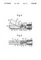
- FIG. 5a sectional view analogous to FIG. 3 of the front part of the instrument shaft with a different embodiment of the cutting instrument
- FIG. 6a view of the subject of FIG. 5 turned through 90° about the axis of the instrument shaft.
- an instrument shaft 11 having a constant circular cross section over the greatest part of its lengthhas the following components disposed concentrically to the central axis 38 proceeding radially from the inside to the outside:
- a conductive bar 17covered with an insulating sleeve 34 and comprising a central rod 17' and a tube 17" firmly mounted on the latter and being extendible from the rest position shown in FIG. 3 in the direction of the arrow into a front end position illustrated in chain-dotted lines;
- a rhombus-shaped wire loop electrodewhich can be fed with a radio frequency current suitable for carrying out a cutting procedure.
- the front ends of the conductive tubes 15, 16are, in accordance with FIG. 4, connected to a first fixed coagulation electrode 12 and to a second fixed coagulation electrode 13 respectively.
- the two elongate and flat coagulation electrodes 12, 13extend essentially parallel to the central axis 38 and form at their proximal ends a hook which is for example angled at right angles.
- the coagulation electrodes 12, 13are partly cylindrically formed in order to establish a continuous transition to the conductive tubes 15, 16 to which they are secured and with which they are electrically connected.
- the cutting electrode 14extends symmetrically between the two coagulation electrodes 12, 13 and is displaceable by forward displacement of the conductive bar 17 out of the position shown in FIGS. 3 and 4 in full lines into the position reproduced in chain-dotted lines.
- a mounting flange 39is provided in the external insulating layer 37 and behind it a ring seal 40.
- a union or sleeve nut 41is located on the instrument shaft 11 and is only schematically illustrated in chain-dotted lines in FIG. 3.
- the distal end of the instrument shaft 11is introduced into a central receiving bore 24 of the fixed part 20 of the actuating head 19.
- the fixed part 20 of the actuating headconsists essentially of a plastic tube 42, with a preferably metallic end piece 43 attached to its front side, with the end piece having a central bore 44 in which a forwardly projecting threaded sleeve 45 is secured.
- the union nut 41is axially screwed onto the external thread of the sleeve 45 and thereby presses the flange 39 against the front side of the threaded sleeve 45 via the seal 40. In this manner, the instrument shaft 11 is releasably secured to the actuating head 19.
- a concentric (coaxial) contact sleeve 46 of insulating materialwhich has eccentric bores 30, 47 extending parallel to the axis 38 at diametrically opposed positions, of which the upper bore is lined in accordance with FIG. 1 with a metallic sleeve 48 so that here a contact bore 30 is present.
- insulating contact sleeve 46Behind the insulating contact sleeve 46 and in axial alignment with the latter, there is provided a further insulating contact sleeve 49 secured to it which has bores 31, 50 axially aligned with the bores 30, 47. Only the bore 31 lying diametrically opposite to the upper bore 30 in FIG. 1 is again lined with a metal sleeve 51.
- the contact sleeve 46has a central contact channel 25 for receiving the conductive tube 15
- the contact sleeve 49is provided with a central contact channel 26 of smaller diameter to receive the conductive tube 16.
- Spring rings 52, 53 arranged in the wall of the contact sleeves 46, 49,ensure a conductive connection between the conductive tubes 15, 16 on the one hand, and the metal sleeves 48, 51 on the other hand.
- the insulating tube 42 and the contact sleeves 46, 48 which are aligned therewith and which are connected axially together by means of the screws 54 which can be seen from FIG. 2,have a common cylindrical outer contour so that a metal guide sleeve 55 can be displaceably mounted thereon while being axially guided.
- the guide sleeve 55carries at its central region a clamping block 56 consisting of insulating material with a slotted central bore 57 through which the rear end of the conductive rod 17 or of the conductive bar 17' extends.
- the conductive bar 17can be releasably secured in the clamping block 56, through a conical union nut 58 and pressure pins 59 which are axially fixed but radially displaceable relative to the guide sleeve 55 and which are connected with the clamping block 56.
- a releasable mounting device 27 for the conductive bar 17is present.
- Electrically conductive contact pins 28, 29are eccentrically fixedly arranged in the clamping block 56 and in alignment with the bores 30, 50 and 31, 47 respectively, with the contact pins 28, 29 engaging in a sliding seat into the bores 30, 50 and 31, 47 respectively.
- the borespreferably also extend in the illustrated manner into regions 60, 61 of the insulating tube 42.
- the rear end of the conductive bar 17contacts a contact pin 63 arranged in an insulating intermediate wall 62 which is connected via a line 64 with a connection coupling 18 provided at the end of the guide sleeve 55.
- Two further cables 65, 66lead, optionally via a capacitor 67, to the two contact pins 28, 29.
- the front end plate 43is pivotally connected via a screw 68 about a transverse axis to a resilient actuating grip 69, the other limb of which is connected via a screw 70 to a guide block 71 secured to the guide sleeve 55, with the guide block 71 being axially displaceably journalled on a guide bar 72 extending from the end plate 43 parallel to the axis 38.
- the guide bar 72is screwed into a corresponding threaded bore of the end plate 43 and a screw head 73 restricts the axial movement apart from one another of the guide sleeve 55 and also the insulating tube 42 brought about by the spring force of the grip 69.
- the instrumentcan be dismantled in that, after screwing off the union nut 41 and releasing the union nut 58, the instrument shaft 11 is first extracted from the actuating head 19
- the actuating handle 69is then screwed away by releasing the screws 68, 70 and the guide rod 72 is removed by rotating it out by means of the screw head 73.
- the movable head part 21can now be axially withdrawn from the fixed head part 20, with the contact pins 28, 29 being withdrawn axially out of the associated bores 30, 50, 60 and 31, 47, 61. All the necessary cleaning and repair work can now be carried out on the actuating head 19.
- the two head parts 20, 21are first put together with the actuating grip 69 to form the actuating head 19.
- the instrument shaft 11 shown in detail in FIGS. 3 and 4is now inserted in the manner schematically illustrated in FIG. 1 with its distal end into the receiving bore 24 until the conductive bar 17 passes through the bore 57 and contacts the contact pin 63 and also the conductive tubes 15, 16 come into electrical contact with the conductive spring rings 52, 53.
- the instrument shaft 11is then finally secured to the actuating head 19 by screwing the union nut 41 onto the threaded sleeve 45.
- the movable head part 21is displaced in the direction of the fixed head part 20, with the conductive bar 17 being moved forwardly relative to the conductive tubes 15, 16 so that the rhombus-like cutting electrode 14, in accordance with FIGS. 3 and 4, is displaced out of the position shown in full lines into the front position illustrated in chain-dotted lines.
- the contact pins 28, 29are thereby displaced in the contact bores 30, 31 while maintaining the electrical contact.
- the cutting electrode 14in accordance with FIGS. 3 and 4, lies between the coagulation electrodes which are bent around in partly cylindrical manner at the end.
- coagulationscan be carried out with the instrument by applying a suitable radio frequency current to the coagulation electrodes 12, 13.
- a cutting processis to be carried out with the cutting electrode 14 then the surgeon actuates a non-illustrated changeover switch whereby a non-illustrated control device connects the two coagulation electrodes 12, 13 together to a single neutral electrode while the cutting electrode 14 is connected on actuation of a switch to a radio frequency current suitable for cutting.
- a non-illustrated control deviceconnects the two coagulation electrodes 12, 13 together to a single neutral electrode while the cutting electrode 14 is connected on actuation of a switch to a radio frequency current suitable for cutting.
- the cutting electrode 14refers to a carrier arm 14"' which is pivotable about a transverse axis 22 with a wire hoop 14' being arranged on the carrier arm and extending in the downwardly pivoted state with a straight part 14" between the two coagulation electrodes 12, 13.
- the part 14"can also be made of wave-shape or of zigzag-shape. An arc-shape is also possible.
- the bearing 23 for the transverse axle 22comprises an insulating block 77 which contains a metal pin 73' which is arranged in the rear region of the coagulation electrodes 12, 13 and extends between them.
- An actuating arm 74 of the cutting electrode 14 which extends behind the transverse axis 22is provided with an elongate slot 75 which extends obliquely to the axis 38.
- a transverse pin 76 in the cam-track engagementextends into this elongate slot 75 and is secured to the front end of the conductive rod 17.
- the elongate slot 75 and the transverse pin 76form a transmission 78 which converts a linear movement into a pivotal movement.
- FIGS. 5 and 6operates during coagulation in the same manner as the embodiment of FIGS. 3 and 4, but in contrast operates in the following manner during cutting:
Landscapes
- Health & Medical Sciences (AREA)
- Surgery (AREA)
- Engineering & Computer Science (AREA)
- Life Sciences & Earth Sciences (AREA)
- Biomedical Technology (AREA)
- Otolaryngology (AREA)
- Nuclear Medicine, Radiotherapy & Molecular Imaging (AREA)
- Plasma & Fusion (AREA)
- Physics & Mathematics (AREA)
- Heart & Thoracic Surgery (AREA)
- Medical Informatics (AREA)
- Molecular Biology (AREA)
- Animal Behavior & Ethology (AREA)
- General Health & Medical Sciences (AREA)
- Public Health (AREA)
- Veterinary Medicine (AREA)
- Surgical Instruments (AREA)
Abstract
Description
The invention relates to a medical radio frequency coagulation-cutting instrument comprising an instrument shaft at the proximal end of which there are provided two stationary coagulation electrodes and a movable cutting electrode; an actuating head arranged at the distal end of the instrument and consisting of a fixed head part and a head part which is movable relative thereto, wherein a relative movement of the two head parts is transmitted to the cutting electrode, wherein the coagulation electrodes and also the cutting electrode lead via radio frequency feedlines, which are led insulated relative to one another in the instrument shaft, to a cable connection which is preferably provided at the distal end for the purpose of connection to a radio frequency supply device, and wherein the radio frequency supply device has at least two switch positions, in one of which the cutting electrode is switched off and the coagulation electrodes are energised with a radio frequency coagulation current and in the other of which one or both of the coagulation electrodes are connected as neutral electrodes and a radio frequency voltage which enables a cutting arc is applied to the cutting electrode and the neutral electrode.
An instrument of this kind is known from the not prior published German Offenlegungsschrift 40 32 271. The two coagulation electrodes and the cutting electrode are axially non-displaceably arranged relative to one another in the instrument shaft. The cutting electrode is however pivotally arranged between the two coagulation electrodes disposed parallel to one another in as much as an outer guide tube can be axially displaced by means of the actuating head.
Furthermore, a pair of coagulation forceps is known (German Patent Specification 27 34 847) in which the two coagulation electrodes can be moved towards one another in forceps-like manner by advancing a rotor by means of the actuating head. A cutting electrode is not provided in this instrument.
Finally, it is known from the non-prior published German Offenlegungsschrift 41 22 219 to form two coagulation electrodes and their feed line as tubes which are arranged coaxially relative to one another and to arrange between them an axially displaceable cutting electrode which is supplied with radio frequency potential via a conductive bar arranged in an insulated manner within the tubes.
The object underlying the invention is to make available a further medical coagulation-cutting instrument. The coagulation-cutting instrument of the invention should in particular satisfy a whole variety of different coagulation and cutting tasks. It should also be easily dismantleable for the purpose of cleaning.
In order to satisfy this object there is provided, in accordance with the present invention, a medical radio frequency coagulation-cutting instrument of the initially named kind but characterised in that the radio frequency supply lines for the two coagulation electrodes are conductive tubes arranged within one another, preferably concentric to one another and to the instrument shaft, with the high frequency supply line for the cutting electrode being arranged inside the conductive tubes in an insulated manner as an axially directed conductive bar axially movable through the actuating head.
As a result of this construction a very stable design of the instrument shaft is ensured on the one hand, while on the other hand the radio frequency potentials and currents necessary to energise the coagulation electrodes and the cutting electrode can be supplied by means of a very compact and stable feedline arrangement. The cutting electrode is thereby supplied with a radio frequency potential suitable for cutting, with the two coagulation electrodes being connected together to form a neutral electrode. In the other switching state, the cutting electrode is retracted into the shaft of the instrument, or removed therefrom, and the two coagulation electrodes are then fed with a radio frequency coagulation current which brings about the desired heating on application of the two stationary coagulation electrodes to the tissue.
The axially movable conductive bar can be solid or can also be hollow and tubular or formed as an assembled body. It is preferably covered with an insulating sleeve and surrounded by a narrow gap so that the relative axial displaceability is ensured.
A preferred embodiment is characterised in that the coagulation electrodes are formed as two hook electrodes which extend at least substantially parallel to one another, with the cutting electrode being movably arranged between the hook electrodes. This embodiment is particularly expedient for engaging the tissue to be coagulated or cut.
In one embodiment the cutting electrode is secured to the proximal end of the conductive bar and is axially displaceable relative to the coagulation electrodes through the conductive bar which is displaceable by means of the actuating head. The cutting electrode can preferably be axially moved between the coagulation electrodes.
For the cutting process it is in this case particularly expedient to use an embodiment in which the cutting electrode is formed as a wire loop, in particular as a rhombic wire.
It is also possible to pivotally arrange the cutting electrode. A preferred embodiment of this kind is characterised in that the cutting electrode is pivotally arranged at the proximal end about a transverse axis and is drivable by the axially movable conductive bar to execute a pivotal cutting movement via a transmission which preferably comprises a pin and a cam-track. The cutting electrode can for example be pivotable in scissors-like manner from a position outside of the coagulation electrodes into a position between the coagulation electrodes.
Moreover, the cutting electrode is expediently formed as a wire hoop with a cutting part which can be brought between the coagulation electrodes, which is preferably at least approximately straight-lined or wave-shaped and which also extends in the inwardly pivoted state between the coagulation electrodes parallel to the latter. In this embodiment the wire hoop is conveniently arranged on a carrying arm which preferably extends parallel to the cutting part. Further advantageous developments of this embodiment can be found in claims 8 and 9.
Preferred embodiments of the actuating head are characterised inclaims 10 to 16.
It is particularly advantageous when the shaft of the instrument is removable from the front end of the actuating head and moreover, when the stationary and movable parts of the actuating head are separable from one another. The individual parts can then each be conveniently cleaned on their own and can also if necessary, be sterilised.
The invention will be described in the following with reference to the drawing in which are shown:
FIG. 1 a partly sectioned side view of the actuating head of the coagulation-cutting instrument of the invention,
FIG. 2 a section on the line II--II in FIG. 1,
FIG. 3 a twice broken away axial section through the instrument shaft of the coagulation-cutting instrument of the invention,
FIG. 4 a sectional view of the front part of the instrument shaft of FIG. 3 turned through 90° about the axis of the instrument shaft relative to FIG. 3,
FIG. 5 a sectional view analogous to FIG. 3 of the front part of the instrument shaft with a different embodiment of the cutting instrument, and
FIG. 6 a view of the subject of FIG. 5 turned through 90° about the axis of the instrument shaft.
In accordance with FIGS. 3 and 4, aninstrument shaft 11 having a constant circular cross section over the greatest part of its length has the following components disposed concentrically to thecentral axis 38 proceeding radially from the inside to the outside:
aconductive bar 17 covered with aninsulating sleeve 34 and comprising a central rod 17' and atube 17" firmly mounted on the latter and being extendible from the rest position shown in FIG. 3 in the direction of the arrow into a front end position illustrated in chain-dotted lines;
agap 35 which permits the axial displacement of theconductive bar 17;
aconductive tube 16;
aninsulating layer 36,
a furtherconductive tube 15; and
an outer insulating layer 37.
At the proximal end of theconductive bar 17, i.e. the end facing the patient, which in the rest position coincides essentially with the front end of theinstrument shaft 11, there is provided a rhombus-shaped wire loop electrode which can be fed with a radio frequency current suitable for carrying out a cutting procedure. The front ends of theconductive tubes coagulation electrode 12 and to a second fixedcoagulation electrode 13 respectively. In accordance with FIGS. 3 and 4, the two elongate andflat coagulation electrodes central axis 38 and form at their proximal ends a hook which is for example angled at right angles. In the rear region thecoagulation electrodes conductive tubes cutting electrode 14 extends symmetrically between the twocoagulation electrodes conductive bar 17 out of the position shown in FIGS. 3 and 4 in full lines into the position reproduced in chain-dotted lines.
In the distal end region of theinstrument shaft 11, amounting flange 39 is provided in the external insulating layer 37 and behind it a ring seal 40. In this region a union or sleeve nut 41 is located on theinstrument shaft 11 and is only schematically illustrated in chain-dotted lines in FIG. 3.
Behind the union nut 41 the different coaxial tubes terminate in stepped manner from the outside towards the inside with ever greater length so that theconductive tubes conductive bar 17 have greater parts of their peripheries exposed and can be brought in the manner which will be described in the following with respect to FIGS. 1 and 2, into a fixed mechanical and electrical connection with the actuatinghead 19.
It should be pointed out that the degree of projection of the individual coaxial elements is shown in FIG. 3 to a different scale from FIG. 1.
In accordance with FIG. 1, the distal end of theinstrument shaft 11 is introduced into acentral receiving bore 24 of thefixed part 20 of the actuatinghead 19. Thefixed part 20 of the actuating head consists essentially of a plastic tube 42, with a preferably metallic end piece 43 attached to its front side, with the end piece having a central bore 44 in which a forwardly projecting threaded sleeve 45 is secured. The union nut 41 is axially screwed onto the external thread of the sleeve 45 and thereby presses theflange 39 against the front side of the threaded sleeve 45 via the seal 40. In this manner, theinstrument shaft 11 is releasably secured to the actuatinghead 19.
Behind the insulating tube 42 there is arranged in axial alignment with it, a concentric (coaxial)contact sleeve 46 of insulating material which has eccentric bores 30, 47 extending parallel to theaxis 38 at diametrically opposed positions, of which the upper bore is lined in accordance with FIG. 1 with a metallic sleeve 48 so that here a contact bore 30 is present.
Behind the insulatingcontact sleeve 46 and in axial alignment with the latter, there is provided a further insulating contact sleeve 49 secured to it which has bores 31, 50 axially aligned with the bores 30, 47. Only the bore 31 lying diametrically opposite to the upper bore 30 in FIG. 1 is again lined with a metal sleeve 51.
While thecontact sleeve 46 has acentral contact channel 25 for receiving theconductive tube 15, the contact sleeve 49 is provided with a central contact channel 26 of smaller diameter to receive theconductive tube 16.
Spring rings 52, 53 arranged in the wall of thecontact sleeves 46, 49, ensure a conductive connection between theconductive tubes
The insulating tube 42 and thecontact sleeves 46, 48 which are aligned therewith and which are connected axially together by means of thescrews 54 which can be seen from FIG. 2, have a common cylindrical outer contour so that ametal guide sleeve 55 can be displaceably mounted thereon while being axially guided.
Theguide sleeve 55 carries at its central region a clamping block 56 consisting of insulating material with a slotted central bore 57 through which the rear end of theconductive rod 17 or of the conductive bar 17' extends. Theconductive bar 17 can be releasably secured in the clamping block 56, through a conical union nut 58 and pressure pins 59 which are axially fixed but radially displaceable relative to theguide sleeve 55 and which are connected with the clamping block 56. Thus, on the whole, a releasable mounting device 27 for theconductive bar 17 is present.
Electrically conductive contact pins 28, 29 are eccentrically fixedly arranged in the clamping block 56 and in alignment with the bores 30, 50 and 31, 47 respectively, with the contact pins 28, 29 engaging in a sliding seat into the bores 30, 50 and 31, 47 respectively.
In order to ensure adequate relative displacement of thehead parts 20, 21, the bores preferably also extend in the illustrated manner into regions 60, 61 of the insulating tube 42.
The rear end of theconductive bar 17 contacts a contact pin 63 arranged in an insulatingintermediate wall 62 which is connected via a line 64 with a connection coupling 18 provided at the end of theguide sleeve 55.
Twofurther cables 65, 66 lead, optionally via acapacitor 67, to the two contact pins 28, 29.
The front end plate 43 is pivotally connected via a screw 68 about a transverse axis to aresilient actuating grip 69, the other limb of which is connected via a screw 70 to a guide block 71 secured to theguide sleeve 55, with the guide block 71 being axially displaceably journalled on a guide bar 72 extending from the end plate 43 parallel to theaxis 38.
The guide bar 72 is screwed into a corresponding threaded bore of the end plate 43 and ascrew head 73 restricts the axial movement apart from one another of theguide sleeve 55 and also the insulating tube 42 brought about by the spring force of thegrip 69.
The instrument can be dismantled in that, after screwing off the union nut 41 and releasing the union nut 58, theinstrument shaft 11 is first extracted from the actuatinghead 19 The actuating handle 69 is then screwed away by releasing the screws 68, 70 and the guide rod 72 is removed by rotating it out by means of thescrew head 73. The movable head part 21 can now be axially withdrawn from the fixedhead part 20, with the contact pins 28, 29 being withdrawn axially out of the associated bores 30, 50, 60 and 31, 47, 61. All the necessary cleaning and repair work can now be carried out on theactuating head 19.
For the renewed assembly of the instrument, the twohead parts 20, 21 are first put together with the actuatinggrip 69 to form theactuating head 19. Theinstrument shaft 11 shown in detail in FIGS. 3 and 4 is now inserted in the manner schematically illustrated in FIG. 1 with its distal end into the receiving bore 24 until theconductive bar 17 passes through the bore 57 and contacts the contact pin 63 and also theconductive tubes instrument shaft 11 is then finally secured to theactuating head 19 by screwing the union nut 41 onto the threaded sleeve 45.
Through pressing together theresilient hand grip 69 the movable head part 21 is displaced in the direction of the fixedhead part 20, with theconductive bar 17 being moved forwardly relative to theconductive tubes like cutting electrode 14, in accordance with FIGS. 3 and 4, is displaced out of the position shown in full lines into the front position illustrated in chain-dotted lines. The contact pins 28, 29 are thereby displaced in the contact bores 30, 31 while maintaining the electrical contact.
On relaxation of theresilient hand grip 69 the twoheads 20, 21 move apart from one another again into the starting position which can be seen from FIGS. 1, 3 and 4.
In the retracted state, the cuttingelectrode 14, in accordance with FIGS. 3 and 4, lies between the coagulation electrodes which are bent around in partly cylindrical manner at the end. In this state, coagulations can be carried out with the instrument by applying a suitable radio frequency current to thecoagulation electrodes
If a cutting process is to be carried out with the cuttingelectrode 14 then the surgeon actuates a non-illustrated changeover switch whereby a non-illustrated control device connects the twocoagulation electrodes electrode 14 is connected on actuation of a switch to a radio frequency current suitable for cutting. By means of the hook-like coagulation electrodes electrode 14
In accordance with FIGS. 5 and 6 in which the same reference numerals are used to designate components which have counterparts in the preceding figures, the cuttingelectrode 14 refers to acarrier arm 14"' which is pivotable about a transverse axis 22 with a wire hoop 14' being arranged on the carrier arm and extending in the downwardly pivoted state with astraight part 14" between the twocoagulation electrodes part 14" can also be made of wave-shape or of zigzag-shape. An arc-shape is also possible.
The bearing 23 for the transverse axle 22 comprises an insulatingblock 77 which contains a metal pin 73' which is arranged in the rear region of thecoagulation electrodes
Anactuating arm 74 of the cuttingelectrode 14 which extends behind the transverse axis 22 is provided with an elongate slot 75 which extends obliquely to theaxis 38. Atransverse pin 76 in the cam-track engagement extends into this elongate slot 75 and is secured to the front end of theconductive rod 17. The elongate slot 75 and thetransverse pin 76 form a transmission 78 which converts a linear movement into a pivotal movement. By advancing theconductive bar 17 out of the position shown in solid lines in FIG. 5 a pivotal movement is thus produced for the cuttingelectrode 14 out of the position shown in continuous lines in FIG. 5 into the position reproduced in chain-dotted lines. Other suitable transmissions can also be used to generate a pivotal movement from a linear movement of theconductive bar 17.
The embodiment of FIGS. 5 and 6 operates during coagulation in the same manner as the embodiment of FIGS. 3 and 4, but in contrast operates in the following manner during cutting:
First of all, with the actuatinggrip 69 pressed (FIG. 1), i.e. in the open state of the cutting electrode 14 (chain-dotted illustration in FIG. 5) a vessel or tissue part is engaged by the hook-like coagulation electrodes electrode 14, i.e. an arc is generated between the wire hoop 14' and thecoagulation electrodes connective bar 17 is retracted, for example by release of thehand grip 69 of FIG. 1, with the wire hoop 14' pivoting between thecoagulation electrodes
Claims (16)
1. Medical radio frequency coagulation-cutting instrument comprising an instrument shaft (11) having a proximal end provided with first and second stationary coagulation electrodes (12, 13) and a movable cutting electrode (14); and an actuating head (19) arranged at a distal end of the instrument (11) and including a fixed head part (20) and a head part (21) which is movable relative thereto, wherein a relative movement of the two head parts (20, 21) is transmitted to the cutting electrode (14) wherein the coagulation electrodes (12, 13) and also the cutting electrode (14) lead via radio frequency supply lines (15, 16, 17), which are insulated relative to one another in the instrument shaft (11), to a cable connection (18) provided at the distal end for connection to a radio frequency supply device, and wherein the radio frequency supply device has at least two switch positions, in one of which the cutting electrode (14) is switched off and the coagulation electrodes (12, 13) are energized with a radio frequency coagulation current and in the other of which at least one of the coagulation electrodes (12, 13) is connected as a neutral electrode and a radio frequency voltage which enables a cutting arc is applied to the cutting electrode (14) and the neutral electrode, characterized in that the radio frequency supply lines for the first and second coagulation electrodes (12, 13) are conductive tubes (15, 16) arranged within one another, the radio frequency supply line for the cutting electrode (14) being arranged inside the conductive tubes in an insulated manner as an axially directed conductive bar (17) axially movable through the actuating head (19).
2. Instrument in accordance with claim 1, characterised in that the coagulation electrodes are formed as two hook electrodes (12, 13) which extend at least substantially parallel to one another, with the cutting electrode (14) being movably arranged between the hook electrodes.
3. Instrument in accordance with claim 1, characterised in that the cutting electrode (14) is secured to the proximal end of the conductive bar (17) and is axially displaceable relative to the coagulation electrodes (12, 13) through the conductive bar (17) which is displaceable by means of the actuating head (19).
4. Instrument in accordance with claim 1, characterised in that the cutting electrode (14) is formed as a wire loop, in particular of rhombic wire.
5. Instrument in accordance with claim 1, characterised in that the cutting electrode (14) is pivotally arranged at the proximal end about a transverse axis (22) and is drivable by the axially movable conductive bar (17) to execute a pivotal cutting movement via a transmission (78) which preferably comprises a pin (76) and a cam-track (75).
6. Instrument in accordance with claim 5, characterised in that the cutting electrode (14) is pivotable in scissors-like manner from a position outside of the coagulation electrodes (12, 13) into a position between the coagulation electrodes (12, 13).
7. Instrument in accordance with claim 5, characterised in that the cutting electrode (14) is formed as a wire hoop (14'), with a cutting part (14") which can be brought between the coagulation electrodes (12, 13), which is preferably at least approximately straight-lined or wave-shaped and which also extends in the inwardly pivoted state between the coagulation electrodes (12, 13) parallel to the latter.
8. Instrument in accordance with claim 7, characterised in that the wire hoop (14') is arranged on a carrying arm (14") which preferably extends parallel to the cutting part (14").
9. Instrument in accordance with claim 5, characterised in that an insulating bearing (23) extends between the coagulation electrodes (12, 13) in their rear region.
10. Instrument in accordance with claim 1, characterised in that the inner conductive tube (16) projects further rearwardly than the outer, conductive tube (15); and in that the fixed head part (20) of the actuating knob or handle (19) has a receiving bore (24) for the distal end of the instrument shaft (11) and behind this, has respective complimentary contact channels (25, 26) which are each aligned with one of the conductive tubes complementary to the latter, by means of which they are electrically connected to the cable connection (18).
11. Instrument in accordance with claim 10, characterised in that the conductive bar (17) projects rearwardly beyond the inner conductive tube (16); and in that a mounting device (27) for the rear end of the conductive bar (17) is provided in the movable head part (21) axially aligned with the contact channels (25, 26).
12. Instrument in accordance with claim 11, characterised in that the head parts (20, 21) are separable from one another; in that eccentrically arranged contact pins (28, 29) extend axially between the movable head part (21) and the stationary head part (20), are fixedly arranged in the one head part (21) and are axially slideably arranged in the other head part (20) in contact bores (30, 31); and in that the securing device (27) for the conductive bar (17) is releasable.
13. Instrument in accordance with claim 12, characterised in that the contact pins (28, 29) are eccentrically and fixedly arranged in an insulating block (32) which simultaneously forms a part of the securing device (27) for the conductive bar (17).
14. Instrument in accordance with claim 1, characterised in that the head parts (20, 21) are axially aligned with one another, essentially behind one another, and are preferably telescopically displaceable within one another.
15. Instrument in accordance with claim 1, characterised in that the head parts (20, 21) are separable from one another.
16. Instrument in accordance with claim 1, characterised in that an electrical plug connection (32) with at least three contacts is provided at the distal end of the movable head part (21).
Applications Claiming Priority (2)
| Application Number | Priority Date | Filing Date | Title |
|---|---|---|---|
| DE4138116ADE4138116A1 (en) | 1991-11-19 | 1991-11-19 | MEDICAL HIGH-FREQUENCY COAGULATION CUTTER |
| DE4138116 | 1991-11-19 |
Publications (1)
| Publication Number | Publication Date |
|---|---|
| US5267998Atrue US5267998A (en) | 1993-12-07 |
Family
ID=6445167
Family Applications (1)
| Application Number | Title | Priority Date | Filing Date |
|---|---|---|---|
| US07/959,210Expired - Fee RelatedUS5267998A (en) | 1991-11-19 | 1992-10-13 | Medical high frequency coagulation cutting instrument |
Country Status (3)
| Country | Link |
|---|---|
| US (1) | US5267998A (en) |
| EP (1) | EP0543122B1 (en) |
| DE (2) | DE4138116A1 (en) |
Cited By (117)
| Publication number | Priority date | Publication date | Assignee | Title |
|---|---|---|---|---|
| US5445638A (en)* | 1993-03-08 | 1995-08-29 | Everest Medical Corporation | Bipolar coagulation and cutting forceps |
| US5458598A (en)* | 1993-12-02 | 1995-10-17 | Cabot Technology Corporation | Cutting and coagulating forceps |
| US5549606A (en)* | 1993-06-10 | 1996-08-27 | Symbiosis Corporation | Endoscopic bipolar electrocautery instruments |
| US5573535A (en)* | 1994-09-23 | 1996-11-12 | United States Surgical Corporation | Bipolar surgical instrument for coagulation and cutting |
| WO1996037156A1 (en)* | 1995-05-22 | 1996-11-28 | Issa Muta M | Resectoscope electrode assembly with simultaneous cutting and coagulation |
| US5603712A (en)* | 1995-06-05 | 1997-02-18 | Frank C. Koranda | Bipola suction tonsillar dissector |
| US5630812A (en)* | 1995-12-11 | 1997-05-20 | Ellman; Alan G. | Electrosurgical handpiece with locking nose piece |
| US5658280A (en)* | 1995-05-22 | 1997-08-19 | Issa; Muta M. | Resectoscope electrode assembly with simultaneous cutting and coagulation |
| US5707392A (en)* | 1995-09-29 | 1998-01-13 | Symbiosis Corporation | Hermaphroditic stamped forceps jaw for disposable endoscopic biopsy forceps and method of making the same |
| US5716374A (en)* | 1995-10-10 | 1998-02-10 | Symbiosis Corporation | Stamped clevis for endoscopic instruments and method of making the same |
| WO1998009575A1 (en)* | 1996-09-06 | 1998-03-12 | Mentor Ophthalmics, Inc. | Bipolar electrosurgical device |
| US5755717A (en)* | 1996-01-16 | 1998-05-26 | Ethicon Endo-Surgery, Inc. | Electrosurgical clamping device with improved coagulation feedback |
| US5766167A (en)* | 1993-12-17 | 1998-06-16 | United States Surgical Corporation | Monopolar electrosurgical Instruments |
| US5810805A (en)* | 1996-02-09 | 1998-09-22 | Conmed Corporation | Bipolar surgical devices and surgical methods |
| US5993445A (en)* | 1995-05-22 | 1999-11-30 | Advanced Closure Systems, Inc. | Resectoscope electrode assembly with simultaneous cutting and coagulation |
| US6024750A (en)* | 1997-08-14 | 2000-02-15 | United States Surgical | Ultrasonic curved blade |
| US6030384A (en)* | 1998-05-01 | 2000-02-29 | Nezhat; Camran | Bipolar surgical instruments having focused electrical fields |
| US6032673A (en)* | 1994-10-13 | 2000-03-07 | Femrx, Inc. | Methods and devices for tissue removal |
| US6036667A (en)* | 1996-10-04 | 2000-03-14 | United States Surgical Corporation | Ultrasonic dissection and coagulation system |
| US6123701A (en)* | 1997-10-09 | 2000-09-26 | Perfect Surgical Techniques, Inc. | Methods and systems for organ resection |
| US6165175A (en)* | 1999-02-02 | 2000-12-26 | Ethicon Endo-Surgery, Inc. | RF bipolar mesentery takedown device including improved bipolar end effector |
| WO2001028444A1 (en)* | 1999-10-15 | 2001-04-26 | Lina Medical Aps | An electrosurgical device for coagulating and for making incisions, a method of severing blood vessels and a method of coagulating and for making incisions in or severing tissue |
| US6296640B1 (en)* | 1998-02-06 | 2001-10-02 | Ethicon Endo-Surgery, Inc. | RF bipolar end effector for use in electrosurgical instruments |
| US20020049438A1 (en)* | 1999-10-05 | 2002-04-25 | Oratec Interventions, Inc. | Surgical instrument having distal face with first and second electrodes |
| US6514252B2 (en) | 1998-05-01 | 2003-02-04 | Perfect Surgical Techniques, Inc. | Bipolar surgical instruments having focused electrical fields |
| US6582427B1 (en) | 1999-03-05 | 2003-06-24 | Gyrus Medical Limited | Electrosurgery system |
| US20030130655A1 (en)* | 1995-06-07 | 2003-07-10 | Arthrocare Corporation | Electrosurgical systems and methods for removing and modifying tissue |
| US6679882B1 (en) | 1998-06-22 | 2004-01-20 | Lina Medical Aps | Electrosurgical device for coagulating and for making incisions, a method of severing blood vessels and a method of coagulating and for making incisions in or severing tissue |
| US6773409B2 (en) | 2001-09-19 | 2004-08-10 | Surgrx Llc | Surgical system for applying ultrasonic energy to tissue |
| US6802843B2 (en) | 2001-09-13 | 2004-10-12 | Csaba Truckai | Electrosurgical working end with resistive gradient electrodes |
| US6869439B2 (en) | 1996-09-19 | 2005-03-22 | United States Surgical Corporation | Ultrasonic dissector |
| US6905497B2 (en) | 2001-10-22 | 2005-06-14 | Surgrx, Inc. | Jaw structure for electrosurgical instrument |
| US20050143769A1 (en)* | 2002-08-19 | 2005-06-30 | White Jeffrey S. | Ultrasonic dissector |
| US6913579B2 (en) | 2001-05-01 | 2005-07-05 | Surgrx, Inc. | Electrosurgical working end and method for obtaining tissue samples for biopsy |
| US6926716B2 (en) | 2001-11-09 | 2005-08-09 | Surgrx Inc. | Electrosurgical instrument |
| US6929644B2 (en) | 2001-10-22 | 2005-08-16 | Surgrx Inc. | Electrosurgical jaw structure for controlled energy delivery |
| US7011657B2 (en) | 2001-10-22 | 2006-03-14 | Surgrx, Inc. | Jaw structure for electrosurgical instrument and method of use |
| US7041102B2 (en) | 2001-10-22 | 2006-05-09 | Surgrx, Inc. | Electrosurgical working end with replaceable cartridges |
| US7070597B2 (en) | 2001-10-18 | 2006-07-04 | Surgrx, Inc. | Electrosurgical working end for controlled energy delivery |
| US7083619B2 (en) | 2001-10-22 | 2006-08-01 | Surgrx, Inc. | Electrosurgical instrument and method of use |
| US7087054B2 (en) | 2002-10-01 | 2006-08-08 | Surgrx, Inc. | Electrosurgical instrument and method of use |
| US7112201B2 (en) | 2001-10-22 | 2006-09-26 | Surgrx Inc. | Electrosurgical instrument and method of use |
| US20060271037A1 (en)* | 2005-05-25 | 2006-11-30 | Forcept, Inc. | Assisted systems and methods for performing transvaginal hysterectomies |
| US7169146B2 (en) | 2003-02-14 | 2007-01-30 | Surgrx, Inc. | Electrosurgical probe and method of use |
| US7189233B2 (en) | 2001-10-22 | 2007-03-13 | Surgrx, Inc. | Electrosurgical instrument |
| US20070244538A1 (en)* | 2005-06-30 | 2007-10-18 | Eder Joseph C | Transvaginal Uterine Artery Occlusion |
| US7309849B2 (en) | 2003-11-19 | 2007-12-18 | Surgrx, Inc. | Polymer compositions exhibiting a PTC property and methods of fabrication |
| US7354440B2 (en) | 2001-10-22 | 2008-04-08 | Surgrx, Inc. | Electrosurgical instrument and method of use |
| US20080097501A1 (en)* | 2006-06-22 | 2008-04-24 | Tyco Healthcare Group Lp | Ultrasonic probe deflection sensor |
| WO2008057410A2 (en) | 2006-11-02 | 2008-05-15 | Peak Surgical, Inc. | Electric plasma-mediated cutting and coagulation of tissue and surgical apparatus |
| US20080119844A1 (en)* | 1992-01-07 | 2008-05-22 | Jean Woloszko | Bipolar electrosurgical clamp for removing and modifying tissue |
| US20080132890A1 (en)* | 1992-01-07 | 2008-06-05 | Arthrocare Corporation | Electrosurgical apparatus and methods for laparoscopy |
| US7485092B1 (en) | 1998-08-12 | 2009-02-03 | Maquet Cardiovascular Llc | Vessel harvesting apparatus and method |
| US20090036881A1 (en)* | 2007-07-30 | 2009-02-05 | Ryan Artale | Polyp removal jaws and method of use |
| US7534243B1 (en) | 1998-08-12 | 2009-05-19 | Maquet Cardiovascular Llc | Dissection and welding of tissue |
| US7632269B2 (en) | 2004-01-16 | 2009-12-15 | Ethicon Endo-Surgery, Inc. | Electrosurgical instrument with replaceable cartridge |
| US7641651B2 (en) | 2005-07-28 | 2010-01-05 | Aragon Surgical, Inc. | Devices and methods for mobilization of the uterus |
| US7695470B1 (en) | 1998-08-12 | 2010-04-13 | Maquet Cardiovascular Llc | Integrated vessel ligator and transector |
| US7794461B2 (en) | 2006-03-08 | 2010-09-14 | Aragon Surgical, Inc. | Method and apparatus for surgical electrocautery |
| US7794393B2 (en) | 2006-04-13 | 2010-09-14 | Larsen Dane M | Resectoscopic device and method |
| US7862565B2 (en) | 2005-05-12 | 2011-01-04 | Aragon Surgical, Inc. | Method for tissue cauterization |
| US7938842B1 (en) | 1998-08-12 | 2011-05-10 | Maquet Cardiovascular Llc | Tissue dissector apparatus |
| US7955331B2 (en) | 2004-03-12 | 2011-06-07 | Ethicon Endo-Surgery, Inc. | Electrosurgical instrument and method of use |
| US8075558B2 (en) | 2002-04-30 | 2011-12-13 | Surgrx, Inc. | Electrosurgical instrument and method |
| US8147489B2 (en) | 2005-01-14 | 2012-04-03 | Covidien Ag | Open vessel sealing instrument |
| US8197633B2 (en) | 2005-09-30 | 2012-06-12 | Covidien Ag | Method for manufacturing an end effector assembly |
| US8257352B2 (en) | 2003-11-17 | 2012-09-04 | Covidien Ag | Bipolar forceps having monopolar extension |
| US8292888B2 (en) | 2001-04-20 | 2012-10-23 | Tyco Healthcare Group Lp | Bipolar or ultrasonic surgical device |
| US8323276B2 (en) | 2007-04-06 | 2012-12-04 | The Board Of Trustees Of The Leland Stanford Junior University | Method for plasma-mediated thermo-electrical ablation with low temperature electrode |
| US8361072B2 (en) | 2005-09-30 | 2013-01-29 | Covidien Ag | Insulating boot for electrosurgical forceps |
| JP2013017542A (en)* | 2011-07-07 | 2013-01-31 | Yamashina Seiki Kk | Endoscope forceps |
| US8394095B2 (en) | 2005-09-30 | 2013-03-12 | Covidien Ag | Insulating boot for electrosurgical forceps |
| US8394096B2 (en) | 2003-11-19 | 2013-03-12 | Covidien Ag | Open vessel sealing instrument with cutting mechanism |
| USD680220S1 (en) | 2012-01-12 | 2013-04-16 | Coviden IP | Slider handle for laparoscopic device |
| US8419727B2 (en) | 2010-03-26 | 2013-04-16 | Aesculap Ag | Impedance mediated power delivery for electrosurgery |
| US8454602B2 (en) | 2009-05-07 | 2013-06-04 | Covidien Lp | Apparatus, system, and method for performing an electrosurgical procedure |
| US8523898B2 (en) | 2009-07-08 | 2013-09-03 | Covidien Lp | Endoscopic electrosurgical jaws with offset knife |
| US8551091B2 (en) | 2002-10-04 | 2013-10-08 | Covidien Ag | Vessel sealing instrument with electrical cutting mechanism |
| US8568444B2 (en) | 2008-10-03 | 2013-10-29 | Covidien Lp | Method of transferring rotational motion in an articulating surgical instrument |
| US8574229B2 (en) | 2006-05-02 | 2013-11-05 | Aesculap Ag | Surgical tool |
| US8591506B2 (en) | 1998-10-23 | 2013-11-26 | Covidien Ag | Vessel sealing system |
| US8632537B2 (en) | 2009-01-05 | 2014-01-21 | Medtronic Advanced Energy Llc | Electrosurgical devices for tonsillectomy and adenoidectomy |
| US8696662B2 (en) | 2005-05-12 | 2014-04-15 | Aesculap Ag | Electrocautery method and apparatus |
| US8728072B2 (en) | 2005-05-12 | 2014-05-20 | Aesculap Ag | Electrocautery method and apparatus |
| US8827992B2 (en) | 2010-03-26 | 2014-09-09 | Aesculap Ag | Impedance mediated control of power delivery for electrosurgery |
| US8852228B2 (en) | 2009-01-13 | 2014-10-07 | Covidien Lp | Apparatus, system, and method for performing an electrosurgical procedure |
| US8870867B2 (en) | 2008-02-06 | 2014-10-28 | Aesculap Ag | Articulable electrosurgical instrument with a stabilizable articulation actuator |
| US8898888B2 (en) | 2009-09-28 | 2014-12-02 | Covidien Lp | System for manufacturing electrosurgical seal plates |
| US8915948B2 (en) | 2002-06-19 | 2014-12-23 | Palomar Medical Technologies, Llc | Method and apparatus for photothermal treatment of tissue at depth |
| US8945125B2 (en) | 2002-11-14 | 2015-02-03 | Covidien Ag | Compressible jaw configuration with bipolar RF output electrodes for soft tissue fusion |
| US8979842B2 (en) | 2011-06-10 | 2015-03-17 | Medtronic Advanced Energy Llc | Wire electrode devices for tonsillectomy and adenoidectomy |
| US9028493B2 (en) | 2009-09-18 | 2015-05-12 | Covidien Lp | In vivo attachable and detachable end effector assembly and laparoscopic surgical instrument and methods therefor |
| US9028536B2 (en) | 2006-08-02 | 2015-05-12 | Cynosure, Inc. | Picosecond laser apparatus and methods for its operation and use |
| US9113898B2 (en) | 2008-10-09 | 2015-08-25 | Covidien Lp | Apparatus, system, and method for performing an electrosurgical procedure |
| US9113940B2 (en) | 2011-01-14 | 2015-08-25 | Covidien Lp | Trigger lockout and kickback mechanism for surgical instruments |
| US9173698B2 (en) | 2010-09-17 | 2015-11-03 | Aesculap Ag | Electrosurgical tissue sealing augmented with a seal-enhancing composition |
| WO2016009703A1 (en)* | 2014-07-15 | 2016-01-21 | 株式会社Jimro | Medical treatment tool and treatment unit thereof |
| US9339327B2 (en) | 2011-06-28 | 2016-05-17 | Aesculap Ag | Electrosurgical tissue dissecting device |
| US9339323B2 (en) | 2005-05-12 | 2016-05-17 | Aesculap Ag | Electrocautery method and apparatus |
| US9780518B2 (en) | 2012-04-18 | 2017-10-03 | Cynosure, Inc. | Picosecond laser apparatus and methods for treating target tissues with same |
| US9848938B2 (en) | 2003-11-13 | 2017-12-26 | Covidien Ag | Compressible jaw configuration with bipolar RF output electrodes for soft tissue fusion |
| US9872724B2 (en) | 2012-09-26 | 2018-01-23 | Aesculap Ag | Apparatus for tissue cutting and sealing |
| US9918778B2 (en) | 2006-05-02 | 2018-03-20 | Aesculap Ag | Laparoscopic radiofrequency surgical device |
| US10143831B2 (en) | 2013-03-14 | 2018-12-04 | Cynosure, Inc. | Electrosurgical systems and methods |
| US10213250B2 (en) | 2015-11-05 | 2019-02-26 | Covidien Lp | Deployment and safety mechanisms for surgical instruments |
| US10245107B2 (en) | 2013-03-15 | 2019-04-02 | Cynosure, Inc. | Picosecond optical radiation systems and methods of use |
| US10251696B2 (en) | 2001-04-06 | 2019-04-09 | Covidien Ag | Vessel sealer and divider with stop members |
| US10299770B2 (en) | 2006-06-01 | 2019-05-28 | Maquet Cardiovascular Llc | Endoscopic vessel harvesting system components |
| US10434324B2 (en) | 2005-04-22 | 2019-10-08 | Cynosure, Llc | Methods and systems for laser treatment using non-uniform output beam |
| US10492849B2 (en) | 2013-03-15 | 2019-12-03 | Cynosure, Llc | Surgical instruments and systems with multimodes of treatments and electrosurgical operation |
| US10507012B2 (en) | 2000-11-17 | 2019-12-17 | Maquet Cardiovascular Llc | Vein harvesting system and method |
| CN112545639A (en)* | 2020-12-29 | 2021-03-26 | 浙江伽奈维医疗科技有限公司 | Radio frequency ablation electrode needle with multi-dimensional nerve monitoring function |
| US10987159B2 (en) | 2015-08-26 | 2021-04-27 | Covidien Lp | Electrosurgical end effector assemblies and electrosurgical forceps configured to reduce thermal spread |
| US11418000B2 (en) | 2018-02-26 | 2022-08-16 | Cynosure, Llc | Q-switched cavity dumped sub-nanosecond laser |
| USD1005484S1 (en) | 2019-07-19 | 2023-11-21 | Cynosure, Llc | Handheld medical instrument and docking base |
| US11819259B2 (en) | 2018-02-07 | 2023-11-21 | Cynosure, Inc. | Methods and apparatus for controlled RF treatments and RF generator system |
| CN120392278A (en)* | 2025-07-01 | 2025-08-01 | 南昌大学第二附属医院 | A high-frequency electric knife with coagulation and cutting functions |
Families Citing this family (5)
| Publication number | Priority date | Publication date | Assignee | Title |
|---|---|---|---|---|
| US6736813B2 (en) | 1998-01-23 | 2004-05-18 | Olympus Optical Co., Ltd. | High-frequency treatment tool |
| US6273887B1 (en) | 1998-01-23 | 2001-08-14 | Olympus Optical Co., Ltd. | High-frequency treatment tool |
| US6197024B1 (en) | 1999-09-22 | 2001-03-06 | Scott Keith Sullivan | Adjustable electrocautery surgical apparatus |
| US7052496B2 (en) | 2001-12-11 | 2006-05-30 | Olympus Optical Co., Ltd. | Instrument for high-frequency treatment and method of high-frequency treatment |
| DE10332564A1 (en)* | 2003-07-11 | 2005-01-27 | Celon Ag Medical Instruments | Surgical device for coagulation or ablation of tissue, comprising hollow shaft accommodating cooling duct and two ring-shaped electrodes |
Citations (2)
| Publication number | Priority date | Publication date | Assignee | Title |
|---|---|---|---|---|
| US4655216A (en)* | 1985-07-23 | 1987-04-07 | Alfred Tischer | Combination instrument for laparoscopical tube sterilization |
| WO1992006642A1 (en)* | 1990-10-17 | 1992-04-30 | Boston Scientific Corporation | Surgical instrument and method |
Family Cites Families (7)
| Publication number | Priority date | Publication date | Assignee | Title |
|---|---|---|---|---|
| CH547103A (en)* | 1973-03-13 | 1974-03-29 | Wullschleger & Schwarz Fa | DEVICE FOR LOCKING AND CUTTING TUBULAR TUBES. |
| DE2415263A1 (en)* | 1974-03-29 | 1975-10-02 | Aesculap Werke Ag | Surgical H.F. coagulation probe has electrode tongs - with exposed ends of insulated conductors forming tong-jaws |
| DE2513868C2 (en)* | 1974-04-01 | 1982-11-04 | Olympus Optical Co., Ltd., Tokyo | Bipolar electrodiathermy forceps |
| SU1220655A1 (en)* | 1983-11-09 | 1986-03-30 | 1-Я Городская Больница Им.Н.И.Пирогова Г.Севастополя | Electrode device for high-frequency electric surgery |
| EP0280972A1 (en)* | 1987-03-04 | 1988-09-07 | Siemens Aktiengesellschaft | Hand piece for a liquid-jet cutting apparatus |
| US4834095A (en)* | 1988-02-16 | 1989-05-30 | Ipco Corporation | Probe unit for electro-surgical device |
| DE4032471C2 (en)* | 1990-10-12 | 1997-02-06 | Delma Elektro Med App | Electrosurgical device |
- 1991
- 1991-11-19DEDE4138116Apatent/DE4138116A1/ennot_activeWithdrawn
- 1992
- 1992-10-01DEDE59206656Tpatent/DE59206656D1/ennot_activeExpired - Fee Related
- 1992-10-01EPEP92116830Apatent/EP0543122B1/ennot_activeExpired - Lifetime
- 1992-10-13USUS07/959,210patent/US5267998A/ennot_activeExpired - Fee Related
Patent Citations (2)
| Publication number | Priority date | Publication date | Assignee | Title |
|---|---|---|---|---|
| US4655216A (en)* | 1985-07-23 | 1987-04-07 | Alfred Tischer | Combination instrument for laparoscopical tube sterilization |
| WO1992006642A1 (en)* | 1990-10-17 | 1992-04-30 | Boston Scientific Corporation | Surgical instrument and method |
Cited By (200)
| Publication number | Priority date | Publication date | Assignee | Title |
|---|---|---|---|---|
| US20080119844A1 (en)* | 1992-01-07 | 2008-05-22 | Jean Woloszko | Bipolar electrosurgical clamp for removing and modifying tissue |
| US7824405B2 (en) | 1992-01-07 | 2010-11-02 | Arthrocare Corporation | Electrosurgical apparatus and methods for laparoscopy |
| US7717912B2 (en) | 1992-01-07 | 2010-05-18 | Arthrocare Corporation | Bipolar electrosurgical clamp for removing and modifying tissue |
| US20080132890A1 (en)* | 1992-01-07 | 2008-06-05 | Arthrocare Corporation | Electrosurgical apparatus and methods for laparoscopy |
| US5445638A (en)* | 1993-03-08 | 1995-08-29 | Everest Medical Corporation | Bipolar coagulation and cutting forceps |
| US5549606A (en)* | 1993-06-10 | 1996-08-27 | Symbiosis Corporation | Endoscopic bipolar electrocautery instruments |
| US5458598A (en)* | 1993-12-02 | 1995-10-17 | Cabot Technology Corporation | Cutting and coagulating forceps |
| US5766167A (en)* | 1993-12-17 | 1998-06-16 | United States Surgical Corporation | Monopolar electrosurgical Instruments |
| US5573535A (en)* | 1994-09-23 | 1996-11-12 | United States Surgical Corporation | Bipolar surgical instrument for coagulation and cutting |
| US6032673A (en)* | 1994-10-13 | 2000-03-07 | Femrx, Inc. | Methods and devices for tissue removal |
| US5993445A (en)* | 1995-05-22 | 1999-11-30 | Advanced Closure Systems, Inc. | Resectoscope electrode assembly with simultaneous cutting and coagulation |
| US5658280A (en)* | 1995-05-22 | 1997-08-19 | Issa; Muta M. | Resectoscope electrode assembly with simultaneous cutting and coagulation |
| WO1996037156A1 (en)* | 1995-05-22 | 1996-11-28 | Issa Muta M | Resectoscope electrode assembly with simultaneous cutting and coagulation |
| US5603712A (en)* | 1995-06-05 | 1997-02-18 | Frank C. Koranda | Bipola suction tonsillar dissector |
| US20030130655A1 (en)* | 1995-06-07 | 2003-07-10 | Arthrocare Corporation | Electrosurgical systems and methods for removing and modifying tissue |
| US7824398B2 (en) | 1995-06-07 | 2010-11-02 | Arthrocare Corporation | Electrosurgical systems and methods for removing and modifying tissue |
| US5707392A (en)* | 1995-09-29 | 1998-01-13 | Symbiosis Corporation | Hermaphroditic stamped forceps jaw for disposable endoscopic biopsy forceps and method of making the same |
| US5716374A (en)* | 1995-10-10 | 1998-02-10 | Symbiosis Corporation | Stamped clevis for endoscopic instruments and method of making the same |
| US5630812A (en)* | 1995-12-11 | 1997-05-20 | Ellman; Alan G. | Electrosurgical handpiece with locking nose piece |
| US5755717A (en)* | 1996-01-16 | 1998-05-26 | Ethicon Endo-Surgery, Inc. | Electrosurgical clamping device with improved coagulation feedback |
| US5810805A (en)* | 1996-02-09 | 1998-09-22 | Conmed Corporation | Bipolar surgical devices and surgical methods |
| US5814043A (en)* | 1996-09-06 | 1998-09-29 | Mentor Ophthalmics, Inc. | Bipolar electrosurgical device |
| US6960200B2 (en) | 1996-09-06 | 2005-11-01 | Medtronic Xomed, Inc. | Package for removable device tips |
| US6358241B1 (en) | 1996-09-06 | 2002-03-19 | Medtronic Xomed, Inc. | Package for removable device tips |
| US6183467B1 (en) | 1996-09-06 | 2001-02-06 | Xomed, Inc. | Package for removable device tips |
| WO1998009575A1 (en)* | 1996-09-06 | 1998-03-12 | Mentor Ophthalmics, Inc. | Bipolar electrosurgical device |
| US6869439B2 (en) | 1996-09-19 | 2005-03-22 | United States Surgical Corporation | Ultrasonic dissector |
| US20080243160A1 (en)* | 1996-09-19 | 2008-10-02 | White Jeffrey S | Ultrasonic Dissector |
| US6036667A (en)* | 1996-10-04 | 2000-03-14 | United States Surgical Corporation | Ultrasonic dissection and coagulation system |
| US6063050A (en)* | 1996-10-04 | 2000-05-16 | United States Surgical Corp. | Ultrasonic dissection and coagulation system |
| US6024750A (en)* | 1997-08-14 | 2000-02-15 | United States Surgical | Ultrasonic curved blade |
| US6468286B2 (en) | 1997-08-14 | 2002-10-22 | The United States Surgical Corporation | Ultrasonic curved blade |
| US6280407B1 (en) | 1997-08-14 | 2001-08-28 | United States Surgical Corporation | Ultrasonic dissection and coagulation system |
| US20110166483A1 (en)* | 1997-08-14 | 2011-07-07 | United States Surgical Corporation | Ultrasonic curved blade |
| US20060122639A1 (en)* | 1997-08-14 | 2006-06-08 | Mastri Dominick L | Ultrasonic curved blade |
| US6682544B2 (en) | 1997-08-14 | 2004-01-27 | United States Surgical Corporation | Ultrasonic curved blade |
| US20040147946A1 (en)* | 1997-08-14 | 2004-07-29 | Mastri Dominick L. | Ultrasonic curved blade |
| US6123701A (en)* | 1997-10-09 | 2000-09-26 | Perfect Surgical Techniques, Inc. | Methods and systems for organ resection |
| US6468275B1 (en) | 1998-02-06 | 2002-10-22 | Ethicon Endo-Surgery, Inc. | RF bipolar mesentery takedown device including improved bipolar end effector |
| US6485490B2 (en) | 1998-02-06 | 2002-11-26 | Ethicon Endo-Surgery, Inc. | RF bipolar end effector for use in electrosurgical instruments |
| US6296640B1 (en)* | 1998-02-06 | 2001-10-02 | Ethicon Endo-Surgery, Inc. | RF bipolar end effector for use in electrosurgical instruments |
| US6162220A (en)* | 1998-05-01 | 2000-12-19 | Perfect Surgical Techniques, Inc. | Bipolar surgical instruments having focused electrical fields |
| US6514252B2 (en) | 1998-05-01 | 2003-02-04 | Perfect Surgical Techniques, Inc. | Bipolar surgical instruments having focused electrical fields |
| US6030384A (en)* | 1998-05-01 | 2000-02-29 | Nezhat; Camran | Bipolar surgical instruments having focused electrical fields |
| US6679882B1 (en) | 1998-06-22 | 2004-01-20 | Lina Medical Aps | Electrosurgical device for coagulating and for making incisions, a method of severing blood vessels and a method of coagulating and for making incisions in or severing tissue |
| US7695470B1 (en) | 1998-08-12 | 2010-04-13 | Maquet Cardiovascular Llc | Integrated vessel ligator and transector |
| US9700398B2 (en) | 1998-08-12 | 2017-07-11 | Maquet Cardiovascular Llc | Vessel harvester |
| US8075559B2 (en) | 1998-08-12 | 2011-12-13 | Maquet Cardiovascular, Llc | Apparatus and method for integrated vessel ligator and transector |
| US7485092B1 (en) | 1998-08-12 | 2009-02-03 | Maquet Cardiovascular Llc | Vessel harvesting apparatus and method |
| US8986335B2 (en) | 1998-08-12 | 2015-03-24 | Maquet Cardiovascular Llc | Tissue dissector apparatus and method |
| US8460331B2 (en) | 1998-08-12 | 2013-06-11 | Maquet Cardiovascular, Llc | Tissue dissector apparatus and method |
| US7938842B1 (en) | 1998-08-12 | 2011-05-10 | Maquet Cardiovascular Llc | Tissue dissector apparatus |
| US20100234843A1 (en)* | 1998-08-12 | 2010-09-16 | Maquet Cardiovascular Llc | Apparatus and method for integrated vessel ligator and transector |
| US9730782B2 (en) | 1998-08-12 | 2017-08-15 | Maquet Cardiovascular Llc | Vessel harvester |
| US7534243B1 (en) | 1998-08-12 | 2009-05-19 | Maquet Cardiovascular Llc | Dissection and welding of tissue |
| US8591506B2 (en) | 1998-10-23 | 2013-11-26 | Covidien Ag | Vessel sealing system |
| US9375270B2 (en) | 1998-10-23 | 2016-06-28 | Covidien Ag | Vessel sealing system |
| US9375271B2 (en) | 1998-10-23 | 2016-06-28 | Covidien Ag | Vessel sealing system |
| US9463067B2 (en) | 1998-10-23 | 2016-10-11 | Covidien Ag | Vessel sealing system |
| US6165175A (en)* | 1999-02-02 | 2000-12-26 | Ethicon Endo-Surgery, Inc. | RF bipolar mesentery takedown device including improved bipolar end effector |
| US20070225699A1 (en)* | 1999-03-05 | 2007-09-27 | Gyrus Medical Limited | Electrosurgery system |
| US6582427B1 (en) | 1999-03-05 | 2003-06-24 | Gyrus Medical Limited | Electrosurgery system |
| US20030153908A1 (en)* | 1999-03-05 | 2003-08-14 | Gyrus Medical Ltd. | Electrosurgery system |
| US9662514B2 (en) | 1999-06-02 | 2017-05-30 | Covidien Lp | Bipolar or ultrasonic surgical device |
| US20020049438A1 (en)* | 1999-10-05 | 2002-04-25 | Oratec Interventions, Inc. | Surgical instrument having distal face with first and second electrodes |
| WO2001028444A1 (en)* | 1999-10-15 | 2001-04-26 | Lina Medical Aps | An electrosurgical device for coagulating and for making incisions, a method of severing blood vessels and a method of coagulating and for making incisions in or severing tissue |
| US10507012B2 (en) | 2000-11-17 | 2019-12-17 | Maquet Cardiovascular Llc | Vein harvesting system and method |
| US10687887B2 (en) | 2001-04-06 | 2020-06-23 | Covidien Ag | Vessel sealer and divider |
| US10265121B2 (en) | 2001-04-06 | 2019-04-23 | Covidien Ag | Vessel sealer and divider |
| US10251696B2 (en) | 2001-04-06 | 2019-04-09 | Covidien Ag | Vessel sealer and divider with stop members |
| US8292888B2 (en) | 2001-04-20 | 2012-10-23 | Tyco Healthcare Group Lp | Bipolar or ultrasonic surgical device |
| US8845665B2 (en) | 2001-04-20 | 2014-09-30 | Covidien Lp | Bipolar or ultrasonic surgical device |
| US8523890B2 (en) | 2001-04-20 | 2013-09-03 | Covidien Lp | Bipolar or ultrasonic surgical device |
| US6913579B2 (en) | 2001-05-01 | 2005-07-05 | Surgrx, Inc. | Electrosurgical working end and method for obtaining tissue samples for biopsy |
| US6802843B2 (en) | 2001-09-13 | 2004-10-12 | Csaba Truckai | Electrosurgical working end with resistive gradient electrodes |
| US6773409B2 (en) | 2001-09-19 | 2004-08-10 | Surgrx Llc | Surgical system for applying ultrasonic energy to tissue |
| US7070597B2 (en) | 2001-10-18 | 2006-07-04 | Surgrx, Inc. | Electrosurgical working end for controlled energy delivery |
| US7041102B2 (en) | 2001-10-22 | 2006-05-09 | Surgrx, Inc. | Electrosurgical working end with replaceable cartridges |
| US7011657B2 (en) | 2001-10-22 | 2006-03-14 | Surgrx, Inc. | Jaw structure for electrosurgical instrument and method of use |
| US7189233B2 (en) | 2001-10-22 | 2007-03-13 | Surgrx, Inc. | Electrosurgical instrument |
| US6929644B2 (en) | 2001-10-22 | 2005-08-16 | Surgrx Inc. | Electrosurgical jaw structure for controlled energy delivery |
| US7981113B2 (en) | 2001-10-22 | 2011-07-19 | Surgrx, Inc. | Electrosurgical instrument |
| US7186253B2 (en) | 2001-10-22 | 2007-03-06 | Surgrx, Inc. | Electrosurgical jaw structure for controlled energy delivery |
| US6905497B2 (en) | 2001-10-22 | 2005-06-14 | Surgrx, Inc. | Jaw structure for electrosurgical instrument |
| US7354440B2 (en) | 2001-10-22 | 2008-04-08 | Surgrx, Inc. | Electrosurgical instrument and method of use |
| US9149326B2 (en) | 2001-10-22 | 2015-10-06 | Ethicon Endo-Surgery, Inc. | Electrosurgical instrument and method |
| US7083619B2 (en) | 2001-10-22 | 2006-08-01 | Surgrx, Inc. | Electrosurgical instrument and method of use |
| US7381209B2 (en) | 2001-10-22 | 2008-06-03 | Surgrx, Inc. | Electrosurgical instrument |
| US7112201B2 (en) | 2001-10-22 | 2006-09-26 | Surgrx Inc. | Electrosurgical instrument and method of use |
| US6926716B2 (en) | 2001-11-09 | 2005-08-09 | Surgrx Inc. | Electrosurgical instrument |
| US8075558B2 (en) | 2002-04-30 | 2011-12-13 | Surgrx, Inc. | Electrosurgical instrument and method |
| US10500413B2 (en) | 2002-06-19 | 2019-12-10 | Palomar Medical Technologies, Llc | Method and apparatus for treatment of cutaneous and subcutaneous conditions |
| US10556123B2 (en) | 2002-06-19 | 2020-02-11 | Palomar Medical Technologies, Llc | Method and apparatus for treatment of cutaneous and subcutaneous conditions |
| US8915948B2 (en) | 2002-06-19 | 2014-12-23 | Palomar Medical Technologies, Llc | Method and apparatus for photothermal treatment of tissue at depth |
| US20050143769A1 (en)* | 2002-08-19 | 2005-06-30 | White Jeffrey S. | Ultrasonic dissector |
| US7087054B2 (en) | 2002-10-01 | 2006-08-08 | Surgrx, Inc. | Electrosurgical instrument and method of use |
| US8551091B2 (en) | 2002-10-04 | 2013-10-08 | Covidien Ag | Vessel sealing instrument with electrical cutting mechanism |
| US8945125B2 (en) | 2002-11-14 | 2015-02-03 | Covidien Ag | Compressible jaw configuration with bipolar RF output electrodes for soft tissue fusion |
| US7169146B2 (en) | 2003-02-14 | 2007-01-30 | Surgrx, Inc. | Electrosurgical probe and method of use |
| US9848938B2 (en) | 2003-11-13 | 2017-12-26 | Covidien Ag | Compressible jaw configuration with bipolar RF output electrodes for soft tissue fusion |
| US8257352B2 (en) | 2003-11-17 | 2012-09-04 | Covidien Ag | Bipolar forceps having monopolar extension |
| US8597296B2 (en) | 2003-11-17 | 2013-12-03 | Covidien Ag | Bipolar forceps having monopolar extension |
| US10441350B2 (en) | 2003-11-17 | 2019-10-15 | Covidien Ag | Bipolar forceps having monopolar extension |
| US7309849B2 (en) | 2003-11-19 | 2007-12-18 | Surgrx, Inc. | Polymer compositions exhibiting a PTC property and methods of fabrication |
| US8394096B2 (en) | 2003-11-19 | 2013-03-12 | Covidien Ag | Open vessel sealing instrument with cutting mechanism |
| US7632269B2 (en) | 2004-01-16 | 2009-12-15 | Ethicon Endo-Surgery, Inc. | Electrosurgical instrument with replaceable cartridge |
| US7955331B2 (en) | 2004-03-12 | 2011-06-07 | Ethicon Endo-Surgery, Inc. | Electrosurgical instrument and method of use |
| US8147489B2 (en) | 2005-01-14 | 2012-04-03 | Covidien Ag | Open vessel sealing instrument |
| US10434324B2 (en) | 2005-04-22 | 2019-10-08 | Cynosure, Llc | Methods and systems for laser treatment using non-uniform output beam |
| US10314642B2 (en) | 2005-05-12 | 2019-06-11 | Aesculap Ag | Electrocautery method and apparatus |
| US8728072B2 (en) | 2005-05-12 | 2014-05-20 | Aesculap Ag | Electrocautery method and apparatus |
| US7942874B2 (en) | 2005-05-12 | 2011-05-17 | Aragon Surgical, Inc. | Apparatus for tissue cauterization |
| US7862565B2 (en) | 2005-05-12 | 2011-01-04 | Aragon Surgical, Inc. | Method for tissue cauterization |
| US8888770B2 (en) | 2005-05-12 | 2014-11-18 | Aesculap Ag | Apparatus for tissue cauterization |
| US9339323B2 (en) | 2005-05-12 | 2016-05-17 | Aesculap Ag | Electrocautery method and apparatus |
| US8696662B2 (en) | 2005-05-12 | 2014-04-15 | Aesculap Ag | Electrocautery method and apparatus |
| US20060271037A1 (en)* | 2005-05-25 | 2006-11-30 | Forcept, Inc. | Assisted systems and methods for performing transvaginal hysterectomies |
| US20070244538A1 (en)* | 2005-06-30 | 2007-10-18 | Eder Joseph C | Transvaginal Uterine Artery Occlusion |
| US7641651B2 (en) | 2005-07-28 | 2010-01-05 | Aragon Surgical, Inc. | Devices and methods for mobilization of the uterus |
| US8197633B2 (en) | 2005-09-30 | 2012-06-12 | Covidien Ag | Method for manufacturing an end effector assembly |
| US8361072B2 (en) | 2005-09-30 | 2013-01-29 | Covidien Ag | Insulating boot for electrosurgical forceps |
| US8394095B2 (en) | 2005-09-30 | 2013-03-12 | Covidien Ag | Insulating boot for electrosurgical forceps |
| US7803156B2 (en) | 2006-03-08 | 2010-09-28 | Aragon Surgical, Inc. | Method and apparatus for surgical electrocautery |
| US7794461B2 (en) | 2006-03-08 | 2010-09-14 | Aragon Surgical, Inc. | Method and apparatus for surgical electrocautery |
| US20100312053A1 (en)* | 2006-04-13 | 2010-12-09 | Larsen Dane M | Resectoscopic device and method |
| US7794393B2 (en) | 2006-04-13 | 2010-09-14 | Larsen Dane M | Resectoscopic device and method |
| US11058478B2 (en) | 2006-05-02 | 2021-07-13 | Aesculap Ag | Laparoscopic radiofrequency surgical device |
| US8574229B2 (en) | 2006-05-02 | 2013-11-05 | Aesculap Ag | Surgical tool |
| US9918778B2 (en) | 2006-05-02 | 2018-03-20 | Aesculap Ag | Laparoscopic radiofrequency surgical device |
| US10299770B2 (en) | 2006-06-01 | 2019-05-28 | Maquet Cardiovascular Llc | Endoscopic vessel harvesting system components |
| US11141055B2 (en) | 2006-06-01 | 2021-10-12 | Maquet Cardiovascular Llc | Endoscopic vessel harvesting system components |
| US11134835B2 (en) | 2006-06-01 | 2021-10-05 | Maquet Cardiovascular Llc | Endoscopic vessel harvesting system components |
| US20080097501A1 (en)* | 2006-06-22 | 2008-04-24 | Tyco Healthcare Group Lp | Ultrasonic probe deflection sensor |
| US9028536B2 (en) | 2006-08-02 | 2015-05-12 | Cynosure, Inc. | Picosecond laser apparatus and methods for its operation and use |
| US10966785B2 (en) | 2006-08-02 | 2021-04-06 | Cynosure, Llc | Picosecond laser apparatus and methods for its operation and use |
| US11712299B2 (en) | 2006-08-02 | 2023-08-01 | Cynosure, LLC. | Picosecond laser apparatus and methods for its operation and use |
| US10849687B2 (en) | 2006-08-02 | 2020-12-01 | Cynosure, Llc | Picosecond laser apparatus and methods for its operation and use |
| WO2008057410A2 (en) | 2006-11-02 | 2008-05-15 | Peak Surgical, Inc. | Electric plasma-mediated cutting and coagulation of tissue and surgical apparatus |
| US20080140066A1 (en)* | 2006-11-02 | 2008-06-12 | Davison Paul O | Electric plasma-mediated cutting and coagulation of tissue and surgical apparatus |
| EP2079382A4 (en)* | 2006-11-02 | 2011-06-22 | Peak Surgical Inc | ELECTRICAL PLASMA-INDUCED TISSUE AND COAGULATION OF TISSUE AND SURGICAL DEVICE |
| US8414572B2 (en) | 2006-11-02 | 2013-04-09 | Medtronic Advanced Energy Llc | Electrosurgery apparatus with partially insulated electrode and exposed edge |
| US8177783B2 (en) | 2006-11-02 | 2012-05-15 | Peak Surgical, Inc. | Electric plasma-mediated cutting and coagulation of tissue and surgical apparatus |
| US8323276B2 (en) | 2007-04-06 | 2012-12-04 | The Board Of Trustees Of The Leland Stanford Junior University | Method for plasma-mediated thermo-electrical ablation with low temperature electrode |
| US20090036881A1 (en)* | 2007-07-30 | 2009-02-05 | Ryan Artale | Polyp removal jaws and method of use |
| AU2008203380B2 (en)* | 2007-07-30 | 2014-01-09 | Covidien Lp | Polyp removal jaws and method of use |
| US8870867B2 (en) | 2008-02-06 | 2014-10-28 | Aesculap Ag | Articulable electrosurgical instrument with a stabilizable articulation actuator |
| US8568444B2 (en) | 2008-10-03 | 2013-10-29 | Covidien Lp | Method of transferring rotational motion in an articulating surgical instrument |
| US9113898B2 (en) | 2008-10-09 | 2015-08-25 | Covidien Lp | Apparatus, system, and method for performing an electrosurgical procedure |
| US8632537B2 (en) | 2009-01-05 | 2014-01-21 | Medtronic Advanced Energy Llc | Electrosurgical devices for tonsillectomy and adenoidectomy |
| US8852228B2 (en) | 2009-01-13 | 2014-10-07 | Covidien Lp | Apparatus, system, and method for performing an electrosurgical procedure |
| US9655674B2 (en) | 2009-01-13 | 2017-05-23 | Covidien Lp | Apparatus, system and method for performing an electrosurgical procedure |
| US10085794B2 (en) | 2009-05-07 | 2018-10-02 | Covidien Lp | Apparatus, system and method for performing an electrosurgical procedure |
| US9345535B2 (en) | 2009-05-07 | 2016-05-24 | Covidien Lp | Apparatus, system and method for performing an electrosurgical procedure |
| US8454602B2 (en) | 2009-05-07 | 2013-06-04 | Covidien Lp | Apparatus, system, and method for performing an electrosurgical procedure |
| US8858554B2 (en) | 2009-05-07 | 2014-10-14 | Covidien Lp | Apparatus, system, and method for performing an electrosurgical procedure |
| US8523898B2 (en) | 2009-07-08 | 2013-09-03 | Covidien Lp | Endoscopic electrosurgical jaws with offset knife |
| US9931131B2 (en) | 2009-09-18 | 2018-04-03 | Covidien Lp | In vivo attachable and detachable end effector assembly and laparoscopic surgical instrument and methods therefor |
| US9028493B2 (en) | 2009-09-18 | 2015-05-12 | Covidien Lp | In vivo attachable and detachable end effector assembly and laparoscopic surgical instrument and methods therefor |
| US8898888B2 (en) | 2009-09-28 | 2014-12-02 | Covidien Lp | System for manufacturing electrosurgical seal plates |
| US10130411B2 (en) | 2010-03-26 | 2018-11-20 | Aesculap Ag | Impedance mediated control of power delivery for electrosurgery |
| US8827992B2 (en) | 2010-03-26 | 2014-09-09 | Aesculap Ag | Impedance mediated control of power delivery for electrosurgery |
| US8419727B2 (en) | 2010-03-26 | 2013-04-16 | Aesculap Ag | Impedance mediated power delivery for electrosurgery |
| US9277962B2 (en) | 2010-03-26 | 2016-03-08 | Aesculap Ag | Impedance mediated control of power delivery for electrosurgery |
| US9173698B2 (en) | 2010-09-17 | 2015-11-03 | Aesculap Ag | Electrosurgical tissue sealing augmented with a seal-enhancing composition |
| US11660108B2 (en) | 2011-01-14 | 2023-05-30 | Covidien Lp | Trigger lockout and kickback mechanism for surgical instruments |
| US9113940B2 (en) | 2011-01-14 | 2015-08-25 | Covidien Lp | Trigger lockout and kickback mechanism for surgical instruments |
| US10383649B2 (en) | 2011-01-14 | 2019-08-20 | Covidien Lp | Trigger lockout and kickback mechanism for surgical instruments |
| US8979842B2 (en) | 2011-06-10 | 2015-03-17 | Medtronic Advanced Energy Llc | Wire electrode devices for tonsillectomy and adenoidectomy |
| US10004555B2 (en) | 2011-06-28 | 2018-06-26 | Aesculap Ag | Electrosurgical tissue dissecting device |
| US9339327B2 (en) | 2011-06-28 | 2016-05-17 | Aesculap Ag | Electrosurgical tissue dissecting device |
| JP2013017542A (en)* | 2011-07-07 | 2013-01-31 | Yamashina Seiki Kk | Endoscope forceps |
| EP2716247A4 (en)* | 2011-07-07 | 2014-12-17 | Yamashina Seiki Co Ltd | ENDOSCOPIC CLAMP |
| USD680220S1 (en) | 2012-01-12 | 2013-04-16 | Coviden IP | Slider handle for laparoscopic device |
| US12068571B2 (en) | 2012-04-18 | 2024-08-20 | Cynosure, Llc | Picosecond laser apparatus and methods for treating target tissues with same |
| US10581217B2 (en) | 2012-04-18 | 2020-03-03 | Cynosure, Llc | Picosecond laser apparatus and methods for treating target tissues with same |
| US11095087B2 (en) | 2012-04-18 | 2021-08-17 | Cynosure, Llc | Picosecond laser apparatus and methods for treating target tissues with same |
| US10305244B2 (en) | 2012-04-18 | 2019-05-28 | Cynosure, Llc | Picosecond laser apparatus and methods for treating target tissues with same |
| US12431683B2 (en) | 2012-04-18 | 2025-09-30 | Cynosure, Llc | Picosecond laser apparatus and methods for treating target tissues with same |
| US9780518B2 (en) | 2012-04-18 | 2017-10-03 | Cynosure, Inc. | Picosecond laser apparatus and methods for treating target tissues with same |
| US11664637B2 (en) | 2012-04-18 | 2023-05-30 | Cynosure, Llc | Picosecond laser apparatus and methods for treating target tissues with same |
| US9872724B2 (en) | 2012-09-26 | 2018-01-23 | Aesculap Ag | Apparatus for tissue cutting and sealing |
| US10143831B2 (en) | 2013-03-14 | 2018-12-04 | Cynosure, Inc. | Electrosurgical systems and methods |
| US10245107B2 (en) | 2013-03-15 | 2019-04-02 | Cynosure, Inc. | Picosecond optical radiation systems and methods of use |
| US11389226B2 (en) | 2013-03-15 | 2022-07-19 | Cynosure, Llc | Surgical instruments and systems with multimodes of treatments and electrosurgical operation |
| US12193734B2 (en) | 2013-03-15 | 2025-01-14 | Cynosure, Llc | Picosecond optical radiation systems and methods of use |
| US11446086B2 (en) | 2013-03-15 | 2022-09-20 | Cynosure, Llc | Picosecond optical radiation systems and methods of use |
| US10765478B2 (en) | 2013-03-15 | 2020-09-08 | Cynosurce, Llc | Picosecond optical radiation systems and methods of use |
| US10492849B2 (en) | 2013-03-15 | 2019-12-03 | Cynosure, Llc | Surgical instruments and systems with multimodes of treatments and electrosurgical operation |
| US10285757B2 (en) | 2013-03-15 | 2019-05-14 | Cynosure, Llc | Picosecond optical radiation systems and methods of use |
| WO2016009703A1 (en)* | 2014-07-15 | 2016-01-21 | 株式会社Jimro | Medical treatment tool and treatment unit thereof |
| US10987159B2 (en) | 2015-08-26 | 2021-04-27 | Covidien Lp | Electrosurgical end effector assemblies and electrosurgical forceps configured to reduce thermal spread |
| US10213250B2 (en) | 2015-11-05 | 2019-02-26 | Covidien Lp | Deployment and safety mechanisms for surgical instruments |
| US11819259B2 (en) | 2018-02-07 | 2023-11-21 | Cynosure, Inc. | Methods and apparatus for controlled RF treatments and RF generator system |
| US11791603B2 (en) | 2018-02-26 | 2023-10-17 | Cynosure, LLC. | Q-switched cavity dumped sub-nanosecond laser |
| US11418000B2 (en) | 2018-02-26 | 2022-08-16 | Cynosure, Llc | Q-switched cavity dumped sub-nanosecond laser |
| USD1005484S1 (en) | 2019-07-19 | 2023-11-21 | Cynosure, Llc | Handheld medical instrument and docking base |
| USD1025356S1 (en) | 2019-07-19 | 2024-04-30 | Cynosure, Llc | Handheld medical instrument and optional docking base |
| USD1097149S1 (en) | 2019-07-19 | 2025-10-07 | Cynosure, Llc | Handheld medical instrument |
| CN112545639A (en)* | 2020-12-29 | 2021-03-26 | 浙江伽奈维医疗科技有限公司 | Radio frequency ablation electrode needle with multi-dimensional nerve monitoring function |
| CN120392278A (en)* | 2025-07-01 | 2025-08-01 | 南昌大学第二附属医院 | A high-frequency electric knife with coagulation and cutting functions |
Also Published As
| Publication number | Publication date |
|---|---|
| EP0543122A1 (en) | 1993-05-26 |
| DE59206656D1 (en) | 1996-08-01 |
| DE4138116A1 (en) | 1993-06-03 |
| EP0543122B1 (en) | 1996-06-26 |
Similar Documents
| Publication | Publication Date | Title |
|---|---|---|
| US5267998A (en) | Medical high frequency coagulation cutting instrument | |
| US5330470A (en) | Electro-surgical treatment instrument | |
| US10918406B2 (en) | Surgical apparatus with jaw force limiter | |
| EP2403422B1 (en) | Surgical apparatus with a tool cartridge including jaws | |
| US4706667A (en) | Electro surgical high frequency cutting instrument | |
| EP1123058B1 (en) | Open vessel sealing forceps with stop member | |
| US2028635A (en) | Forcipated surgical instrument | |
| CA1146225A (en) | Disposable electrosurgical instrument | |
| US6511480B1 (en) | Open vessel sealing forceps with disposable electrodes | |
| US3532095A (en) | Electrosurgical instrument | |
| CN108186111B (en) | Multi-mode composite electrosurgical device | |
| US8361071B2 (en) | Vessel sealing forceps with disposable electrodes | |
| US20100331742A1 (en) | Surgical operating apparatus | |
| US3920021A (en) | Coagulating devices | |
| DE112008003419B4 (en) | Surgical device with removable instrument plug-in module | |
| EP2679176B1 (en) | Surgical forceps | |
| CA2934191C (en) | Surgical forceps | |
| JP2959843B2 (en) | Electrosurgical handpiece with blade and gas function | |
| US5290286A (en) | Bipolar instrument utilizing one stationary electrode and one movable electrode | |
| US6190386B1 (en) | Electrosurgical forceps with needle electrodes | |
| US9107672B2 (en) | Vessel sealing forceps with disposable electrodes | |
| RU2709679C2 (en) | Bipolar electrosurgical actuator | |
| US20080171938A1 (en) | Ultrasonic operating apparatus | |
| US5626577A (en) | Manually extendable electrocautery surgical apparatus | |
| US20040054365A1 (en) | Electrosurgical system |
Legal Events
| Date | Code | Title | Description |
|---|---|---|---|
| AS | Assignment | Owner name:DELMA ELEKTRO-UND MEDIZINISCHE APPARATEBAU GESELLS Free format text:ASSIGNMENT OF ASSIGNORS INTEREST.;ASSIGNOR:HAGEN, ALFRED;REEL/FRAME:006291/0836 Effective date:19920902 | |
| FEPP | Fee payment procedure | Free format text:PAYOR NUMBER ASSIGNED (ORIGINAL EVENT CODE: ASPN); ENTITY STATUS OF PATENT OWNER: SMALL ENTITY | |
| FPAY | Fee payment | Year of fee payment:4 | |
| FPAY | Fee payment | Year of fee payment:8 | |
| SULP | Surcharge for late payment | Year of fee payment:7 | |
| FEPP | Fee payment procedure | Free format text:PAYOR NUMBER ASSIGNED (ORIGINAL EVENT CODE: ASPN); ENTITY STATUS OF PATENT OWNER: SMALL ENTITY Free format text:PAYER NUMBER DE-ASSIGNED (ORIGINAL EVENT CODE: RMPN); ENTITY STATUS OF PATENT OWNER: SMALL ENTITY | |
| REMI | Maintenance fee reminder mailed | ||
| LAPS | Lapse for failure to pay maintenance fees | ||
| STCH | Information on status: patent discontinuation | Free format text:PATENT EXPIRED DUE TO NONPAYMENT OF MAINTENANCE FEES UNDER 37 CFR 1.362 | |
| FP | Lapsed due to failure to pay maintenance fee | Effective date:20051207 |