US5267871A - Switching electrical connector - Google Patents
Switching electrical connectorDownload PDFInfo
- Publication number
- US5267871A US5267871AUS07/908,697US90869792AUS5267871AUS 5267871 AUS5267871 AUS 5267871AUS 90869792 AUS90869792 AUS 90869792AUS 5267871 AUS5267871 AUS 5267871A
- Authority
- US
- United States
- Prior art keywords
- insulator
- contacts
- shell
- portions
- electrical connector
- Prior art date
- Legal status (The legal status is an assumption and is not a legal conclusion. Google has not performed a legal analysis and makes no representation as to the accuracy of the status listed.)
- Expired - Lifetime
Links
- 239000012212insulatorSubstances0.000claimsabstractdescription47
- 230000000717retained effectEffects0.000claimsabstractdescription4
- 238000005452bendingMethods0.000claims1
- 230000014759maintenance of locationEffects0.000claims1
- 230000037431insertionEffects0.000description2
- 238000003780insertionMethods0.000description2
- 239000004020conductorSubstances0.000description1
- 238000010276constructionMethods0.000description1
- 238000004512die castingMethods0.000description1
- 239000002184metalSubstances0.000description1
- 238000000465mouldingMethods0.000description1
Images

Classifications
- H—ELECTRICITY
- H01—ELECTRIC ELEMENTS
- H01R—ELECTRICALLY-CONDUCTIVE CONNECTIONS; STRUCTURAL ASSOCIATIONS OF A PLURALITY OF MUTUALLY-INSULATED ELECTRICAL CONNECTING ELEMENTS; COUPLING DEVICES; CURRENT COLLECTORS
- H01R13/00—Details of coupling devices of the kinds covered by groups H01R12/70 or H01R24/00 - H01R33/00
- H01R13/66—Structural association with built-in electrical component
- H01R13/70—Structural association with built-in electrical component with built-in switch
- H01R13/703—Structural association with built-in electrical component with built-in switch operated by engagement or disengagement of coupling parts, e.g. dual-continuity coupling part
- H01R13/7031—Shorting, shunting or bussing of different terminals interrupted or effected on engagement of coupling part, e.g. for ESD protection, line continuity
- H01R13/7033—Shorting, shunting or bussing of different terminals interrupted or effected on engagement of coupling part, e.g. for ESD protection, line continuity making use of elastic extensions of the terminals
- Y—GENERAL TAGGING OF NEW TECHNOLOGICAL DEVELOPMENTS; GENERAL TAGGING OF CROSS-SECTIONAL TECHNOLOGIES SPANNING OVER SEVERAL SECTIONS OF THE IPC; TECHNICAL SUBJECTS COVERED BY FORMER USPC CROSS-REFERENCE ART COLLECTIONS [XRACs] AND DIGESTS
- Y10—TECHNICAL SUBJECTS COVERED BY FORMER USPC
- Y10S—TECHNICAL SUBJECTS COVERED BY FORMER USPC CROSS-REFERENCE ART COLLECTIONS [XRACs] AND DIGESTS
- Y10S439/00—Electrical connectors
- Y10S439/944—Coaxial connector having circuit-interrupting provision effected by mating or having "dead" contact activated after mating
Definitions
- the inventionpertains to an electrical connector with an internal switch, and particularly, an internal switch that is actuated by connection with another electrical connector.
- a known electrical connector with an internal switchis disclosed in U.S. Pat. No. 5,073,123, and comprises, a conductive exterior shell concentrically encircling an insulator, and a pair of switch contacts encircled by the insulator, the switch contacts engaging one another, and one of the switch contacts being deflected by a plug contact of another electrical connector to open the switch.
- an electrical connectorcomprises, an internal switch constructed with a pair of conductive switch contacts retained within an insulator.
- the insulatoris encircled by a conductive shell having a stepped interior. The contacts retain the insulator immobile against the stepped interior.
- Electrical terminals on the contactsproject from the insulator and from the shell for connection to a circuit board.
- the insulatorresists movement of the contacts during connection of the terminals to a circuit board, and during deflection of one of the switch contacts by a plug contact of another electrical connector.
- FIG. 1is an elevation view in section of an electrical connector with an internal switch
- FIG. 2is an end view of the connector shown in FIG. 1;
- FIG. 3is an elevation view of a switch contact of the connector shown in FIG. 1;
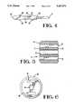
- FIG. 4is a top plan view of the contact shown in FIG. 3;
- FIG. 5is an elevation view in section of one portion of an insulator of the connector shown in FIG. 1;
- FIG. 6is an end view of the insulator shown in FIG. 5;
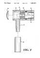
- FIG. 7is an elevation view in section with parts shown separated from one another of an electrical plug connector.
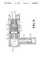
- FIG. 8is a view similar to FIGS. 1 and 7 illustrating mated connection of the connectors shown in FIGS. 1 and 7.
- an electrical connector 1 having an internal switch 2comprises, a conductive exterior shell 3, a two piece insulator 4, and a pair of conductive switch contacts 5, 6.
- the shell 3comprises, a hollow cylindrical portion 7, having an open front end 8 and an open rear end 9.
- the shell 3projects from a broadened base 10, FIG. 2. Projecting in an opposite direction are mounting feet 11 for mounting against a circuit board, not shown. Extended posts 12 project from the mounting feet 11 for insertion into apertures of the circuit board, not shown.
- the portion 7 and the base 10are of unitary construction, fabricated, for example, by die casting.
- the mounting feet 11 and posts 12also are fabricated unitary with the base 10. Electrical terminals 13 of the contacts 5, 6, FIG. 1, project from the insulator 4 and from the base 10 of the shell 3 for connection to the circuit board, not shown, for example, by insertion into apertures of the circuit board.
- the insulator 4is comprised of two identical portions 14, one of which will now be described.
- Each portion 14 of the insulator 4is fabricated by molding with a cylindrical shape 15 fitting against the internal diameter of the cylindrical portion 7 of the shell 3.
- a coaxial passage 16 of cylindrical shapeextends through the portion 14 from one end 17 to another identical end 18.
- the passage 16is between a pair of spaced apart, contact receiving cavities 19 rectangular in cross section, extending parallel to the passage 16 from one end 17 to the other end 18.
- the contact 6is shaped at its exterior edges as shown in FIG. 4, for example, by stamping and forming a flat strip of metal.
- the exterior shapeincludes the unitary terminal 13 and two spaced apart sets of projecting barbs 20 and 21 that are wedge shaped.
- the wedge shapetapers toward the nearest of the ends 22 and 23 of the contact 6.
- the contact 5is identically shaped at its exterior edges.
- the portion 24is outlined on three of its four sides by a slit 25 through the thickness of the contact 6. The portion 24 is then bent to project out of the plane of thickness, FIG. 3, and to have a curved free end 26 that engages the other contact 5.
- Front ends 22 of the contacts 5, 6are assembled into the cavities 19 of a first insulator portion 14, with the terminals 13 projecting outwardly.
- the first set of barbs 20 on each of the contacts 5, 6secures the first insulator 14 onto each of the contacts 5, 6.
- the contacts 5, 6are assembled into the front end 8 of the shell 3, the terminals 13 being inserted first into the shell 3.
- the first insulator portion 14is inserted into the front end 8 of the shell 3, and will engage an internal shoulder 29 of the shell 3 facing toward the front end 8 to limit movement of the insulator portion 14 inwardly of the shell 3.
- the shoulder 29is provided by a stepped interior 30 of the shell 3.
- the terminals 13will project out the rear end 9 of the shell 3.
- the second insulator portion 14is then assembled over the terminals 13, with the terminals 13 being received in the cavities 19.
- the second insulator portion 14is moved over the terminals 13, and then moved over the contacts 5, 6, until engaging a rear facing shoulder 31 of the shell 3 to limit movement of the second insulator portion 14 inwardly of the shell 3.
- the second set of barbs 21 on each of the contacts 5, 6secures the second insulator portion 14 onto each of the contacts 5, 6.
- Each of the electrical contacts 5, 6is retained within the insulator portions 14 by the barbs 20, 21.
- the contacts 5, 6retain the insulator portions 14 immobile against the stepped interior 30 of the shell 3.
- the second insulator portion 14resists movement of the terminals 13 in a direction inwardly of the shell 3, especially during connection of the terminals 13 to a circuit board, not shown.
- the internal shoulders 29, 31are spaced apart and define an air gap 32 between the two portions 14 of the insulator 4.
- the portion 24 of the contact 16projects along the air gap 32 to engage the other contact 15, and provides a normally closed switch 2.
- the plug 33comprises, a conductive outer shell 34 with resilient spring fingers 35 arranged in a cylinder shape for concentric connection to the shell 3 of the connector 1.
- the shell 34has a cap 36 and a sleeve 37 for connection to a conductive sheath of a coaxial electrical cable, not shown.
- a crimp ferrule 38is concentrically assembled over the sleeve 37 to clamp the sheath of a coaxial cable.
- the plug 33includes an insulator 39 within the shell 34, and a conductive plug contact 40 concentrically within the insulator 39 for connection to a center conductor of a coaxial cable, not shown.
- the plug contact 40is inserted along the passage 16 of the connector 1 when the connector 33 is connected to the connector 1.
- the portion 24 of the contact 6is constructed as a resilient spring to be resiliently deflectable by the plug contact 40 received along the passage 16.
- the plug contact 40bends solely the portion 24 out of engagement with the contact 5, thereby opening the switch 2, and electrically connecting the plug contact 40 with the contact 6 having the portion 24.
- An electrical connector 1comprises, internal switch contacts 5, 6 held by an insulator 4, wherein the insulator 4 resists movement of the contacts 5, 6 during connection of the terminals 13 to a circuit board, and during deflection of one of the switch contacts 6 by a plug contact 39 of another electrical connector 33.
- the contacts 5, 6retain the insulator 4 immobile against a stepped interior 30 of the shell 3.
Landscapes
- Details Of Connecting Devices For Male And Female Coupling (AREA)
Abstract
Description
The invention pertains to an electrical connector with an internal switch, and particularly, an internal switch that is actuated by connection with another electrical connector.
A known electrical connector with an internal switch is disclosed in U.S. Pat. No. 5,073,123, and comprises, a conductive exterior shell concentrically encircling an insulator, and a pair of switch contacts encircled by the insulator, the switch contacts engaging one another, and one of the switch contacts being deflected by a plug contact of another electrical connector to open the switch.
According to the invention an electrical connector comprises, an internal switch constructed with a pair of conductive switch contacts retained within an insulator. The insulator is encircled by a conductive shell having a stepped interior. The contacts retain the insulator immobile against the stepped interior.
Electrical terminals on the contacts project from the insulator and from the shell for connection to a circuit board. The insulator resists movement of the contacts during connection of the terminals to a circuit board, and during deflection of one of the switch contacts by a plug contact of another electrical connector.
The invention will now be described by way of example with reference to the drawings, according to which;
FIG. 1 is an elevation view in section of an electrical connector with an internal switch;
FIG. 2 is an end view of the connector shown in FIG. 1;
FIG. 3 is an elevation view of a switch contact of the connector shown in FIG. 1;
FIG. 4 is a top plan view of the contact shown in FIG. 3;
FIG. 5 is an elevation view in section of one portion of an insulator of the connector shown in FIG. 1;
FIG. 6 is an end view of the insulator shown in FIG. 5;
FIG. 7 is an elevation view in section with parts shown separated from one another of an electrical plug connector; and
FIG. 8 is a view similar to FIGS. 1 and 7 illustrating mated connection of the connectors shown in FIGS. 1 and 7.
With reference to FIG. 1, anelectrical connector 1 having aninternal switch 2 comprises, aconductive exterior shell 3, a twopiece insulator 4, and a pair ofconductive switch contacts shell 3 comprises, a hollowcylindrical portion 7, having anopen front end 8 and an open rear end 9. Theshell 3 projects from a broadenedbase 10, FIG. 2. Projecting in an opposite direction are mountingfeet 11 for mounting against a circuit board, not shown. Extendedposts 12 project from themounting feet 11 for insertion into apertures of the circuit board, not shown. Theportion 7 and thebase 10 are of unitary construction, fabricated, for example, by die casting. The mountingfeet 11 andposts 12 also are fabricated unitary with thebase 10.Electrical terminals 13 of thecontacts insulator 4 and from thebase 10 of theshell 3 for connection to the circuit board, not shown, for example, by insertion into apertures of the circuit board.
With reference to FIGS. 1, 5 and 6, theinsulator 4 is comprised of twoidentical portions 14, one of which will now be described. Eachportion 14 of theinsulator 4 is fabricated by molding with acylindrical shape 15 fitting against the internal diameter of thecylindrical portion 7 of theshell 3. Acoaxial passage 16 of cylindrical shape extends through theportion 14 from oneend 17 to anotheridentical end 18. Thepassage 16 is between a pair of spaced apart, contact receivingcavities 19 rectangular in cross section, extending parallel to thepassage 16 from oneend 17 to theother end 18.
With reference to FIG. 4, thecontact 6 will now be described. Thecontact 6 is shaped at its exterior edges as shown in FIG. 4, for example, by stamping and forming a flat strip of metal. The exterior shape includes theunitary terminal 13 and two spaced apart sets of projectingbarbs ends contact 6. Thecontact 5 is identically shaped at its exterior edges.
Only thecontact 6 is formed with acantilever beam portion 24 within the outer edges, FIG. 4. Theportion 24 is outlined on three of its four sides by aslit 25 through the thickness of thecontact 6. Theportion 24 is then bent to project out of the plane of thickness, FIG. 3, and to have a curvedfree end 26 that engages theother contact 5.
With reference to FIG. 1, assembly of theconnector 1 will now be described.Front ends 22 of thecontacts cavities 19 of afirst insulator portion 14, with theterminals 13 projecting outwardly. The first set ofbarbs 20 on each of thecontacts first insulator 14 onto each of thecontacts contacts front end 8 of theshell 3, theterminals 13 being inserted first into theshell 3. Thefirst insulator portion 14 is inserted into thefront end 8 of theshell 3, and will engage aninternal shoulder 29 of theshell 3 facing toward thefront end 8 to limit movement of theinsulator portion 14 inwardly of theshell 3. Theshoulder 29 is provided by astepped interior 30 of theshell 3. Theterminals 13 will project out the rear end 9 of theshell 3. Thesecond insulator portion 14 is then assembled over theterminals 13, with theterminals 13 being received in thecavities 19. Thesecond insulator portion 14 is moved over theterminals 13, and then moved over thecontacts shoulder 31 of theshell 3 to limit movement of thesecond insulator portion 14 inwardly of theshell 3. The second set ofbarbs 21 on each of thecontacts second insulator portion 14 onto each of thecontacts
Each of theelectrical contacts insulator portions 14 by thebarbs contacts insulator portions 14 immobile against thestepped interior 30 of theshell 3. Thesecond insulator portion 14 resists movement of theterminals 13 in a direction inwardly of theshell 3, especially during connection of theterminals 13 to a circuit board, not shown. Theinternal shoulders air gap 32 between the twoportions 14 of theinsulator 4. Theportion 24 of thecontact 16 projects along theair gap 32 to engage theother contact 15, and provides a normally closedswitch 2.
With reference to FIGS. 7 and 8, anelectrical connector plug 33 will be described. Theplug 33 comprises, a conductiveouter shell 34 withresilient spring fingers 35 arranged in a cylinder shape for concentric connection to theshell 3 of theconnector 1. Theshell 34 has acap 36 and asleeve 37 for connection to a conductive sheath of a coaxial electrical cable, not shown. Acrimp ferrule 38 is concentrically assembled over thesleeve 37 to clamp the sheath of a coaxial cable. Theplug 33 includes aninsulator 39 within theshell 34, and aconductive plug contact 40 concentrically within theinsulator 39 for connection to a center conductor of a coaxial cable, not shown. Theplug contact 40 is inserted along thepassage 16 of theconnector 1 when theconnector 33 is connected to theconnector 1. Theportion 24 of thecontact 6 is constructed as a resilient spring to be resiliently deflectable by theplug contact 40 received along thepassage 16. The plug contact 40 bends solely theportion 24 out of engagement with thecontact 5, thereby opening theswitch 2, and electrically connecting theplug contact 40 with thecontact 6 having theportion 24.
Anelectrical connector 1 comprises,internal switch contacts insulator 4, wherein theinsulator 4 resists movement of thecontacts terminals 13 to a circuit board, and during deflection of one of theswitch contacts 6 by aplug contact 39 of anotherelectrical connector 33. Thecontacts insulator 4 immobile against a steppedinterior 30 of theshell 3.
Claims (7)
1. An electrical connector having an internal switch, comprising: a conductive exterior shell with a stepped interior, an insulator divided into two identical portions and encircled by the shell, and a pair of electrical contacts retained within the insulator, a plug contact receiving passage encircled by the insulator, and a portion of one of the contacts extending to engage the other of the contacts, the portion being constructed to be resiliently deflectable upon a plug contact received along the passage an bending solely the portion out of engagement with said other of the contacts, and the contacts retaining the insulator immobile against the stepped interior of the shell.
2. An electrical connector as recited in claim 1, comprising: both portions of the insulator being received in opposite open ends of the shell and engaging spaced apart internal shoulders of the shell to limit movement of the two portions of the insulator inwardly of the shell.
3. An electrical connector as recited in claim 1, comprising: the internal shoulders being spaced apart and defining an air gap between the two portions of the insulator, and the portion of one of the contacts projecting along the air gap to engage the other of the contacts.
4. An electrical connector as recited in claim 1, comprising: the contacts being locked to the two portions of the insulator.
5. An electrical connector as recited in claim 4, comprising: the contacts having two retention barbs retaining the two portions of the insulator immobile with respect to the contacts.
6. An electrical connector as recited in claim 4, comprising: electrical terminals on the contacts extending outwardly of one of the two portions of the insulator, and extending outwardly of one open end of the shell for connection to a circuit board.
7. An electrical connector as recited in claim 6, comprising: the terminals project from one of the portions of the insulator, and one of the internal shoulders resisting movement of said corresponding one of the portions of the insulator in a direction inwardly of the shell, and said corresponding one of the portions of the insulator resisting movement of the terminals in a direction inwardly of the shell.
Priority Applications (1)
| Application Number | Priority Date | Filing Date | Title |
|---|---|---|---|
| US07/908,697US5267871A (en) | 1992-07-02 | 1992-07-02 | Switching electrical connector |
Applications Claiming Priority (1)
| Application Number | Priority Date | Filing Date | Title |
|---|---|---|---|
| US07/908,697US5267871A (en) | 1992-07-02 | 1992-07-02 | Switching electrical connector |
Publications (1)
| Publication Number | Publication Date |
|---|---|
| US5267871Atrue US5267871A (en) | 1993-12-07 |
Family
ID=25426129
Family Applications (1)
| Application Number | Title | Priority Date | Filing Date |
|---|---|---|---|
| US07/908,697Expired - LifetimeUS5267871A (en) | 1992-07-02 | 1992-07-02 | Switching electrical connector |
Country Status (1)
| Country | Link |
|---|---|
| US (1) | US5267871A (en) |
Cited By (14)
| Publication number | Priority date | Publication date | Assignee | Title |
|---|---|---|---|---|
| US5368494A (en)* | 1993-05-13 | 1994-11-29 | Lai; Yang-Chuan | BNC T-type adapter |
| US5580261A (en)* | 1994-02-04 | 1996-12-03 | Radiall | Coaxial electrical connector also performing a switching function |
| US5693924A (en)* | 1995-06-28 | 1997-12-02 | The Whitaker Corporation | Switching contact mechanism with wipe and backwipe |
| EP0739052A3 (en)* | 1995-04-20 | 1997-12-10 | J.E. Thomas Specialties Limited | Circuitry for use with coaxial cable distribution networks |
| US5741146A (en)* | 1996-10-29 | 1998-04-21 | The Whitaker Corporation | Coaxial switch |
| US5989046A (en)* | 1997-05-12 | 1999-11-23 | Smk Corporation | Coaxial connector with switch |
| US6079994A (en)* | 1998-01-30 | 2000-06-27 | The Whitaker Corporation | Switching connector |
| EP0942496A3 (en)* | 1998-03-12 | 2001-08-01 | Siemens Aktiengesellschaft | Coaxial connector |
| US6296525B1 (en) | 2000-01-07 | 2001-10-02 | J. D'addario & Company, Inc. | Electrical plug and jack connectors |
| US6533617B1 (en) | 2000-01-07 | 2003-03-18 | J. D'addario & Company, Inc. | Electrical plug connectors |
| US20040121625A1 (en)* | 2002-08-07 | 2004-06-24 | Smk Corporation | Coaxial connector with switch |
| US20040229481A1 (en)* | 2003-05-12 | 2004-11-18 | International Business Machines Corporation | Method and apparatus for providing positive contact force in an electrical assembly |
| CN1694312B (en)* | 2004-04-30 | 2010-08-04 | Ims连接器系统有限公司 | Electric plug and socket connecting device |
| US20100323542A1 (en)* | 2009-06-18 | 2010-12-23 | Thomas & Betts International, Inc. | Electrical connector |
Citations (6)
| Publication number | Priority date | Publication date | Assignee | Title |
|---|---|---|---|---|
| US2312002A (en)* | 1940-12-05 | 1943-02-23 | Arthur J Schmitt | Electrical connector |
| US3949180A (en)* | 1973-09-03 | 1976-04-06 | Hoshidenki-Seizo Kabushiki Kaisha | Jack |
| US4633048A (en)* | 1984-12-30 | 1986-12-30 | Hosiden Electronics Co., Ltd. | Jack with a switch |
| US5030123A (en)* | 1989-03-24 | 1991-07-09 | Adc Telecommunications, Inc. | Connector and patch panel for digital video and data |
| US5108300A (en)* | 1991-04-16 | 1992-04-28 | Amp Incorporated | Electrical connector with interlocked components |
| US5112236A (en)* | 1990-05-17 | 1992-05-12 | Societe Cetra S.A.R.L. | Electrical contact |
- 1992
- 1992-07-02USUS07/908,697patent/US5267871A/ennot_activeExpired - Lifetime
Patent Citations (6)
| Publication number | Priority date | Publication date | Assignee | Title |
|---|---|---|---|---|
| US2312002A (en)* | 1940-12-05 | 1943-02-23 | Arthur J Schmitt | Electrical connector |
| US3949180A (en)* | 1973-09-03 | 1976-04-06 | Hoshidenki-Seizo Kabushiki Kaisha | Jack |
| US4633048A (en)* | 1984-12-30 | 1986-12-30 | Hosiden Electronics Co., Ltd. | Jack with a switch |
| US5030123A (en)* | 1989-03-24 | 1991-07-09 | Adc Telecommunications, Inc. | Connector and patch panel for digital video and data |
| US5112236A (en)* | 1990-05-17 | 1992-05-12 | Societe Cetra S.A.R.L. | Electrical contact |
| US5108300A (en)* | 1991-04-16 | 1992-04-28 | Amp Incorporated | Electrical connector with interlocked components |
Cited By (17)
| Publication number | Priority date | Publication date | Assignee | Title |
|---|---|---|---|---|
| US5368494A (en)* | 1993-05-13 | 1994-11-29 | Lai; Yang-Chuan | BNC T-type adapter |
| US5580261A (en)* | 1994-02-04 | 1996-12-03 | Radiall | Coaxial electrical connector also performing a switching function |
| EP0739052A3 (en)* | 1995-04-20 | 1997-12-10 | J.E. Thomas Specialties Limited | Circuitry for use with coaxial cable distribution networks |
| US5693924A (en)* | 1995-06-28 | 1997-12-02 | The Whitaker Corporation | Switching contact mechanism with wipe and backwipe |
| US5741146A (en)* | 1996-10-29 | 1998-04-21 | The Whitaker Corporation | Coaxial switch |
| US5989046A (en)* | 1997-05-12 | 1999-11-23 | Smk Corporation | Coaxial connector with switch |
| US6079994A (en)* | 1998-01-30 | 2000-06-27 | The Whitaker Corporation | Switching connector |
| EP0942496A3 (en)* | 1998-03-12 | 2001-08-01 | Siemens Aktiengesellschaft | Coaxial connector |
| US6296525B1 (en) | 2000-01-07 | 2001-10-02 | J. D'addario & Company, Inc. | Electrical plug and jack connectors |
| US6390856B1 (en) | 2000-01-07 | 2002-05-21 | J. D'addario & Company, Inc. | Electrical plug and jack connectors |
| US6533617B1 (en) | 2000-01-07 | 2003-03-18 | J. D'addario & Company, Inc. | Electrical plug connectors |
| US20040121625A1 (en)* | 2002-08-07 | 2004-06-24 | Smk Corporation | Coaxial connector with switch |
| US6790047B2 (en)* | 2002-08-07 | 2004-09-14 | Smk Corporation | Coaxial connector with switch |
| US20040229481A1 (en)* | 2003-05-12 | 2004-11-18 | International Business Machines Corporation | Method and apparatus for providing positive contact force in an electrical assembly |
| CN1694312B (en)* | 2004-04-30 | 2010-08-04 | Ims连接器系统有限公司 | Electric plug and socket connecting device |
| US20100323542A1 (en)* | 2009-06-18 | 2010-12-23 | Thomas & Betts International, Inc. | Electrical connector |
| US8328573B2 (en) | 2009-06-18 | 2012-12-11 | Thomas & Betts International, Inc. | Electrical connector |
Similar Documents
| Publication | Publication Date | Title |
|---|---|---|
| US4416504A (en) | Contact with dual cantilevered arms with narrowed, complimentary tip portions | |
| EP1304770B1 (en) | Coaxial connector with a switch | |
| JP2706309B2 (en) | Electrical connector assembly | |
| US3178673A (en) | Wire connector | |
| US5267871A (en) | Switching electrical connector | |
| US5697815A (en) | Electrical connectors | |
| US5893767A (en) | Electrical connector having a switch | |
| US3275765A (en) | Electrical connecting and switch device | |
| US6574855B1 (en) | Method of making a switch-equipped coaxial connector | |
| US5135417A (en) | Dual usage electrical/electronic pin terminal system | |
| KR870001865B1 (en) | Rib cage terminal | |
| US6319030B1 (en) | Switching receptacle connector | |
| US5073123A (en) | Self terminating tap connector | |
| US6010377A (en) | High contact force pin-receiving electrical terminal | |
| US5133672A (en) | Insulation displacement terminal | |
| US3777301A (en) | Terminals and connectors for interconnecting conductors and male contacts | |
| EP0562652B1 (en) | Electrical terminal | |
| US4373766A (en) | Electrical connector assembly | |
| US6811450B1 (en) | Electrical receptacle-type terminal | |
| JPH07192819A (en) | Coaxial connector | |
| US3312931A (en) | Electrical connector and housing | |
| JP3044378U (en) | Flat insulation-cut terminal for electrical connectors | |
| US6905373B2 (en) | Electrical contact for cable assembly | |
| US6336820B2 (en) | Switch-equipped coaxial connector | |
| GB2130448A (en) | Improvements in electrical contact members and electrical connector assemblies |
Legal Events
| Date | Code | Title | Description |
|---|---|---|---|
| AS | Assignment | Owner name:AMP INCORPORATED, PENNSYLVANIA Free format text:ASSIGNMENT OF ASSIGNORS INTEREST.;ASSIGNOR:FLANAGAN, JAMES R.;REEL/FRAME:006176/0084 Effective date:19920803 | |
| AS | Assignment | Owner name:AMP INVESTMENTS, DELAWARE Free format text:ASSIGNMENT OF ASSIGNORS INTEREST;ASSIGNOR:AMP INCORPORATED;REEL/FRAME:006714/0652 Effective date:19920812 Owner name:WHITAKER CORPORATION, THE, DELAWARE Free format text:ASSIGNMENT OF ASSIGNORS INTEREST;ASSIGNOR:AMP INVESTMENTS;REEL/FRAME:006714/0644 Effective date:19920812 | |
| STCF | Information on status: patent grant | Free format text:PATENTED CASE | |
| FPAY | Fee payment | Year of fee payment:4 | |
| FPAY | Fee payment | Year of fee payment:8 | |
| REMI | Maintenance fee reminder mailed | ||
| FEPP | Fee payment procedure | Free format text:PAYOR NUMBER ASSIGNED (ORIGINAL EVENT CODE: ASPN); ENTITY STATUS OF PATENT OWNER: LARGE ENTITY | |
| FPAY | Fee payment | Year of fee payment:12 |