US5267289A - Ion implantation of nuclear fuel assembly components using cathodic vacuum arc source - Google Patents
Ion implantation of nuclear fuel assembly components using cathodic vacuum arc sourceDownload PDFInfo
- Publication number
- US5267289A US5267289AUS07/951,234US95123492AUS5267289AUS 5267289 AUS5267289 AUS 5267289AUS 95123492 AUS95123492 AUS 95123492AUS 5267289 AUS5267289 AUS 5267289A
- Authority
- US
- United States
- Prior art keywords
- component
- source material
- chamber
- ions
- plasma
- Prior art date
- Legal status (The legal status is an assumption and is not a legal conclusion. Google has not performed a legal analysis and makes no representation as to the accuracy of the status listed.)
- Expired - Lifetime
Links
- 239000003758nuclear fuelSubstances0.000titleclaimsabstractdescription9
- 238000005468ion implantationMethods0.000titleclaimsdescription10
- 150000002500ionsChemical class0.000claimsabstractdescription26
- 238000000034methodMethods0.000claimsabstractdescription25
- 239000000463materialSubstances0.000claimsabstractdescription20
- 239000007943implantSubstances0.000claimsabstractdescription14
- 238000002513implantationMethods0.000claimsabstractdescription13
- IJGRMHOSHXDMSA-UHFFFAOYSA-NAtomic nitrogenChemical compoundN#NIJGRMHOSHXDMSA-UHFFFAOYSA-N0.000claimsabstractdescription12
- 239000007789gasSubstances0.000claimsabstractdescription7
- 229910052757nitrogenInorganic materials0.000claimsabstractdescription6
- 229910052726zirconiumInorganic materials0.000claimsabstractdescription6
- -1Zr or TiChemical class0.000claimsabstractdescription5
- 229910052719titaniumInorganic materials0.000claimsabstractdescription5
- 229910052751metalInorganic materials0.000claimsabstractdescription4
- 239000012080ambient airSubstances0.000claimsabstractdescription3
- 230000002708enhancing effectEffects0.000claimsabstract4
- 150000008040ionic compoundsChemical class0.000claimsabstract4
- 239000002184metalSubstances0.000claimsabstract3
- 239000000470constituentSubstances0.000claimsabstract2
- 229910001093Zr alloyInorganic materials0.000claimsdescription6
- 238000005253claddingMethods0.000claimsdescription3
- 230000007935neutral effectEffects0.000claimsdescription3
- 150000004767nitridesChemical class0.000claimsdescription3
- 229910045601alloyInorganic materials0.000claims2
- 239000000956alloySubstances0.000claims2
- 238000001914filtrationMethods0.000claims1
- 229910052735hafniumInorganic materials0.000claims1
- 229910052715tantalumInorganic materials0.000claims1
- ATJFFYVFTNAWJD-UHFFFAOYSA-NTinChemical compound[Sn]ATJFFYVFTNAWJD-UHFFFAOYSA-N0.000abstractdescription4
- 229910021645metal ionInorganic materials0.000description9
- 239000004411aluminiumSubstances0.000description7
- 229910052782aluminiumInorganic materials0.000description7
- 239000000523sampleSubstances0.000description7
- 239000000758substrateSubstances0.000description7
- 230000008569processEffects0.000description6
- XUIMIQQOPSSXEZ-UHFFFAOYSA-NSiliconChemical compound[Si]XUIMIQQOPSSXEZ-UHFFFAOYSA-N0.000description5
- XAGFODPZIPBFFR-UHFFFAOYSA-NaluminiumChemical compound[Al]XAGFODPZIPBFFR-UHFFFAOYSA-N0.000description5
- 239000003990capacitorSubstances0.000description5
- 239000000446fuelSubstances0.000description5
- 229910052710siliconInorganic materials0.000description5
- 239000010703siliconSubstances0.000description5
- 238000007747platingMethods0.000description4
- 241000894007speciesSpecies0.000description4
- RYGMFSIKBFXOCR-UHFFFAOYSA-NCopperChemical compound[Cu]RYGMFSIKBFXOCR-UHFFFAOYSA-N0.000description3
- 229910052802copperInorganic materials0.000description3
- 239000010949copperSubstances0.000description3
- 238000000151depositionMethods0.000description3
- 238000002149energy-dispersive X-ray emission spectroscopyMethods0.000description3
- 230000015556catabolic processEffects0.000description2
- 239000011651chromiumSubstances0.000description2
- 230000008021depositionEffects0.000description2
- 238000007599dischargingMethods0.000description2
- 239000012212insulatorSubstances0.000description2
- 230000010354integrationEffects0.000description2
- 238000012986modificationMethods0.000description2
- 239000004065semiconductorSubstances0.000description2
- 238000000926separation methodMethods0.000description2
- 239000000126substanceSubstances0.000description2
- 235000009027Amelanchier alnifoliaNutrition0.000description1
- 244000068687Amelanchier alnifoliaSpecies0.000description1
- VYZAMTAEIAYCRO-UHFFFAOYSA-NChromiumChemical compound[Cr]VYZAMTAEIAYCRO-UHFFFAOYSA-N0.000description1
- 239000004809TeflonSubstances0.000description1
- 229920006362Teflon®Polymers0.000description1
- 230000004913activationEffects0.000description1
- PNEYBMLMFCGWSK-UHFFFAOYSA-Naluminium oxideInorganic materials[O-2].[O-2].[O-2].[Al+3].[Al+3]PNEYBMLMFCGWSK-UHFFFAOYSA-N0.000description1
- 238000000137annealingMethods0.000description1
- 230000015572biosynthetic processEffects0.000description1
- 239000010406cathode materialSubstances0.000description1
- 229910052804chromiumInorganic materials0.000description1
- 239000011248coating agentSubstances0.000description1
- 238000000576coating methodMethods0.000description1
- 150000001875compoundsChemical class0.000description1
- 238000007796conventional methodMethods0.000description1
- 238000005260corrosionMethods0.000description1
- 230000007797corrosionEffects0.000description1
- 239000013078crystalSubstances0.000description1
- 238000009792diffusion processMethods0.000description1
- 238000009826distributionMethods0.000description1
- 239000002019doping agentSubstances0.000description1
- 239000000428dustSubstances0.000description1
- 230000004907fluxEffects0.000description1
- 230000000977initiatory effectEffects0.000description1
- 238000010884ion-beam techniqueMethods0.000description1
- 150000001247metal acetylidesChemical class0.000description1
- 230000004048modificationEffects0.000description1
- 238000001556precipitationMethods0.000description1
- 230000009467reductionEffects0.000description1
- 238000005070samplingMethods0.000description1
- 229920006395saturated elastomerPolymers0.000description1
- 239000007787solidSubstances0.000description1
- 238000010186stainingMethods0.000description1
- 238000004381surface treatmentMethods0.000description1
- 235000012431wafersNutrition0.000description1
Images

Classifications
- C—CHEMISTRY; METALLURGY
- C23—COATING METALLIC MATERIAL; COATING MATERIAL WITH METALLIC MATERIAL; CHEMICAL SURFACE TREATMENT; DIFFUSION TREATMENT OF METALLIC MATERIAL; COATING BY VACUUM EVAPORATION, BY SPUTTERING, BY ION IMPLANTATION OR BY CHEMICAL VAPOUR DEPOSITION, IN GENERAL; INHIBITING CORROSION OF METALLIC MATERIAL OR INCRUSTATION IN GENERAL
- C23C—COATING METALLIC MATERIAL; COATING MATERIAL WITH METALLIC MATERIAL; SURFACE TREATMENT OF METALLIC MATERIAL BY DIFFUSION INTO THE SURFACE, BY CHEMICAL CONVERSION OR SUBSTITUTION; COATING BY VACUUM EVAPORATION, BY SPUTTERING, BY ION IMPLANTATION OR BY CHEMICAL VAPOUR DEPOSITION, IN GENERAL
- C23C14/00—Coating by vacuum evaporation, by sputtering or by ion implantation of the coating forming material
- C23C14/0021—Reactive sputtering or evaporation
- C—CHEMISTRY; METALLURGY
- C23—COATING METALLIC MATERIAL; COATING MATERIAL WITH METALLIC MATERIAL; CHEMICAL SURFACE TREATMENT; DIFFUSION TREATMENT OF METALLIC MATERIAL; COATING BY VACUUM EVAPORATION, BY SPUTTERING, BY ION IMPLANTATION OR BY CHEMICAL VAPOUR DEPOSITION, IN GENERAL; INHIBITING CORROSION OF METALLIC MATERIAL OR INCRUSTATION IN GENERAL
- C23C—COATING METALLIC MATERIAL; COATING MATERIAL WITH METALLIC MATERIAL; SURFACE TREATMENT OF METALLIC MATERIAL BY DIFFUSION INTO THE SURFACE, BY CHEMICAL CONVERSION OR SUBSTITUTION; COATING BY VACUUM EVAPORATION, BY SPUTTERING, BY ION IMPLANTATION OR BY CHEMICAL VAPOUR DEPOSITION, IN GENERAL
- C23C14/00—Coating by vacuum evaporation, by sputtering or by ion implantation of the coating forming material
- C23C14/22—Coating by vacuum evaporation, by sputtering or by ion implantation of the coating forming material characterised by the process of coating
- C23C14/24—Vacuum evaporation
- C23C14/32—Vacuum evaporation by explosion; by evaporation and subsequent ionisation of the vapours, e.g. ion-plating
- C23C14/325—Electric arc evaporation
- C—CHEMISTRY; METALLURGY
- C23—COATING METALLIC MATERIAL; COATING MATERIAL WITH METALLIC MATERIAL; CHEMICAL SURFACE TREATMENT; DIFFUSION TREATMENT OF METALLIC MATERIAL; COATING BY VACUUM EVAPORATION, BY SPUTTERING, BY ION IMPLANTATION OR BY CHEMICAL VAPOUR DEPOSITION, IN GENERAL; INHIBITING CORROSION OF METALLIC MATERIAL OR INCRUSTATION IN GENERAL
- C23C—COATING METALLIC MATERIAL; COATING MATERIAL WITH METALLIC MATERIAL; SURFACE TREATMENT OF METALLIC MATERIAL BY DIFFUSION INTO THE SURFACE, BY CHEMICAL CONVERSION OR SUBSTITUTION; COATING BY VACUUM EVAPORATION, BY SPUTTERING, BY ION IMPLANTATION OR BY CHEMICAL VAPOUR DEPOSITION, IN GENERAL
- C23C14/00—Coating by vacuum evaporation, by sputtering or by ion implantation of the coating forming material
- C23C14/22—Coating by vacuum evaporation, by sputtering or by ion implantation of the coating forming material characterised by the process of coating
- C23C14/48—Ion implantation
- G—PHYSICS
- G21—NUCLEAR PHYSICS; NUCLEAR ENGINEERING
- G21C—NUCLEAR REACTORS
- G21C21/00—Apparatus or processes specially adapted to the manufacture of reactors or parts thereof
- G21C21/02—Manufacture of fuel elements or breeder elements contained in non-active casings
- G—PHYSICS
- G21—NUCLEAR PHYSICS; NUCLEAR ENGINEERING
- G21C—NUCLEAR REACTORS
- G21C3/00—Reactor fuel elements and their assemblies; Selection of substances for use as reactor fuel elements
- H—ELECTRICITY
- H01—ELECTRIC ELEMENTS
- H01J—ELECTRIC DISCHARGE TUBES OR DISCHARGE LAMPS
- H01J2237/00—Discharge tubes exposing object to beam, e.g. for analysis treatment, etching, imaging
- H01J2237/02—Details
- H01J2237/022—Avoiding or removing foreign or contaminating particles, debris or deposits on sample or tube
- Y—GENERAL TAGGING OF NEW TECHNOLOGICAL DEVELOPMENTS; GENERAL TAGGING OF CROSS-SECTIONAL TECHNOLOGIES SPANNING OVER SEVERAL SECTIONS OF THE IPC; TECHNICAL SUBJECTS COVERED BY FORMER USPC CROSS-REFERENCE ART COLLECTIONS [XRACs] AND DIGESTS
- Y02—TECHNOLOGIES OR APPLICATIONS FOR MITIGATION OR ADAPTATION AGAINST CLIMATE CHANGE
- Y02E—REDUCTION OF GREENHOUSE GAS [GHG] EMISSIONS, RELATED TO ENERGY GENERATION, TRANSMISSION OR DISTRIBUTION
- Y02E30/00—Energy generation of nuclear origin
- Y02E30/30—Nuclear fission reactors
Definitions
- the present inventionrelate to the surface treatment of nuclear fuel assembly components such as fuel rod cladding and control rod guide tubes.
- U.S. Pat. No. 4,724,016discloses the use of ion implantation, particularly N, to enhance the wear and/or corrosion resistance of a zirconium alloy fuel rod cladding.
- the implantation processshould be carried out without depositing a superstrate, i.e., plating surface, that dimensionally alters the component.
- PSIIplasma source ion implantation
- J. R. Conrad et alIEEE International Conference on Plasma Science, Saskatoon, Canada, May 19-21, 1986.
- PSIIinvolves immersing the object to be implanted into a steady-state gaseous plasma and repetitively pulse biasing the object to a high negative voltage, thereby accelerating the ions across the sheath and implanting them into the target.
- PSIIis unsuitable for the plating-free implantation of metal ions due to the collection of low-energy ions, and therefore plating of the substrate between bias pulses.
- Godechot and Yudeveloped a surface-modification technique in which metal ion guns were used for simultaneous low-energy ion deposition and high-energy ion implantation.
- I. G. Brown et alApplied Physics Letters 58, 1392 (1991).
- the process described by themis designed to avoid the possibility of plating since the plasma pulse contains no neutral atoms or macroparticles and the substrate is always biased so that there is no low-energy streaming plasma; therefore, the size and geometry of the substance is preserved.
- silicon wafershave been implanted with aluminium ions at doses of up to 3 ⁇ 10 14 /cm 2 , but the process is energy intensive.
- Chan, Meassick and Srodahave recently reported the use of a cathodic arc with electromagnetic dust filter as a source of highly energetic metal ions. The ions are then used for plating-free metal-ion implantation.
- C. Chan et al"Plating-free Metal Ion Implantation Utilizing the Cathodic Vacuum Arc As An Ion Source", Appl. Phy. Lett., Vol. 60., No. 2 (March 1992).
- an object of the present inventionto provide an improved system and method for the implantation of metal ions onto nuclear fuel assembly components such as fuel rods, without plating.
- This objectis achieved by utilizing a cathodic vacuum arc as a cost-effective source of high energy ions that can penetrate the component substrate to greater depth than conventional ion implantation techniques, without the deposition of a surface coating. Depths of approximately 0.2 ⁇ m are achievable with nitride implantation species, with energy reduction of at least an order of a magnitude (depending on the implant species) relative to conventional techniques such as those of the Anthony patent, Conrad et al, and Godechot et al.
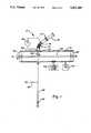
- FIG. 1is a schematic of the system for performing the ion implantation.
- FIG. 2is a detailed schematic of a cathodic arc metal ion source usable with the system of FIG. 1.
- the inventionwill be described in the overall context of the implantation of ZrN or TiN onto the outer surface of a zirconium alloy tubular component of a nuclear fuel assembly. The description is based on the apparatus, method and results reported for implantation of aluminium ions into silicon, by C. Chan et al in the article identified above.
- the apparatus 10 for the implantation of ZrN or TiN into a tubular fuel assembly componentis shown in FIG. 1 and comprises a pulsed cathodic arc metal-ion source 12, an electromagnetic duct 14 for separation of the ions from the macroparticles, and an implantation chamber 16.
- FIG. 2One suitable cathodic arc metal-ion source 12 is shown in FIG. 2. It comprises a cylindrical cathode 18 surrounded by an annular trigger ring 20 with an alumina (A1 2 0 3 ) insulator 22 between the cathode and the trigger.
- the cathodeis made of Zr or Ti while the trigger ring 20 and the anode cylinder 24 are made of copper.
- the anodeis located 5 cm from the cathode 18 and has a small hole 26 through which a portion of the plasma plume 28 streams out.
- the ring 20is suspended around the cathode 18, from a Teflon seat 30 at the other end of the anode 24.
- the arc between the cathode 18 and anode 24is driven by a capacitive discharge circuit consisting of a 0.12 ohm resistor 32 and a 2500 ⁇ F capacitor 34 charged to approximately 2 kv.
- a spark gap circuit including gap 38, 250 kohm resistor 40, and 0.1 ⁇ f capacitor 42are connected to the trigger ring 20. Breakdown across the spark gap 38 upon full energization of capacitor 34 results in a high-voltage pulse being applied to the trigger ring 20, initiating a surface-charge breakdown across the insulator 22 to the cathode 18. This creates one or more cathode spots.
- Ionization of cathode materialcloses the main anode-cathode loop, discharging the pulse line and creating a plasma plume 28.
- the main arc current pulsewas approximately 100 ⁇ s in length with an average current of 1000 A. Approximately 5% of the arc current resulted in ions, creating 5 ⁇ 10 -3 C of ion charge. Of this, approximately 10% drifted through the anode hole 26 and entered the duct 14. The duct transmits approximately 10% of the incoming ions into the implant chamber resulting in approximately 5 ⁇ 10 -5 C being available for implantation.
- the electromagnetic duct 14comprises a copper conduit with a 45° bend, around which 150 turns of water-cooled copper tubing 46 have been wound.
- a current source 48 of 100 A through the tubingproduces a longitudinal magnetic field within the duct with a strength of 300 G at the bend and 100 G at the entrance and exit ports 50, 52 of the duct.
- This magnetic fieldguides the ions from the source 12 around the 45° bend and into the implant chamber 16 while neutral atoms and macroparticles travel in a line-of-sight into the wall 54 of the tube.
- a 45 V biasis applied to the duct 14 to reduce ion losses to the walls 54, resulting in a plasma flux at the exit 52 of the duct that is very highly ionized and free of macroparticles.
- the implant chamber 16is a 30-cm-diam by 30-cm-long vessel pumped by a turbomolecular pump 56 to an ultimate pressure of 1 ⁇ 10 -7 Torr. During the implantation process, the chamber pressure rose to 1 ⁇ 10 -5 Torr at which the ion mean-free path was several meters.
- the chamber end walls 58, 60(or separate fixturing means, not shown) support the fuel assembly tubular component 62 on the chamber axis, so as to be pulled and rotated under the duct exit 52 in the center of the implant chamber.
- the fixture or substrate tube 62is biasable through 2 megaohm resistor 66 to -25 kv at 64.
- a 10 nF capacitor 68was used to limit the voltage drop on the substrate 62 during the implant pulse.
- the implantation chamber 16is backfilled with nitrogen from source 53 after evacuation of ambient air, so that the zirconium ions emerging from the duct at 52, react with the nitrogen to form ZrN, which in turn enters the substrate 62.
- other metallic elements or compoundscan be implanted according to the invention, including nitrides (e.g., CrN, TiN, HfN, and TaN), carbides (e.g., TiC, CrC, and ZrC), and chromium (Cr). It would be within the skill of the ordinary practitioner to optimize the parameters for generating a metallic plasma plume and, where appropriate, a reactive gas in the chamber 16, to produce the desired implant species.
- the total ion charge injected into the implant chamberwas determined by scanning a Langmuir probe, biased at -90 V to repel electrons across the exit of the electromagnetic duct.
- the total charge of the pulsewas found by a radial integration to be 5.1 ⁇ 10 -8 C/pulse.
- the ion dose per pulsewas calculated to be 1.9 ⁇ 10 11 ions/pulse.
- the voltage of the substratedrops from approximately 2.5 to 5 kV.
- the measured implanted doseincreases linearly until 300,000 plasma pulses had been implanted, after which the measured dose saturated at a value of 1 ⁇ 10 14 /cm 2 .
- the concentration of aluminium in siliconexceeded the solid solubility limit of 2 ⁇ 10 19 /cm 3 , the dopant is precipitated out of the crystal during the anneal cycle, and does not contribute to the measured dose utilizing this technique.
- EDSEnergy dispersive spectroscopy
Landscapes
- Chemical & Material Sciences (AREA)
- Engineering & Computer Science (AREA)
- Physics & Mathematics (AREA)
- Mechanical Engineering (AREA)
- Chemical Kinetics & Catalysis (AREA)
- Materials Engineering (AREA)
- Metallurgy (AREA)
- Organic Chemistry (AREA)
- High Energy & Nuclear Physics (AREA)
- General Engineering & Computer Science (AREA)
- Plasma & Fusion (AREA)
- Manufacturing & Machinery (AREA)
- Physical Vapour Deposition (AREA)
Abstract
Description
Claims (13)
Priority Applications (1)
| Application Number | Priority Date | Filing Date | Title |
|---|---|---|---|
| US07/951,234US5267289A (en) | 1992-09-25 | 1992-09-25 | Ion implantation of nuclear fuel assembly components using cathodic vacuum arc source |
Applications Claiming Priority (1)
| Application Number | Priority Date | Filing Date | Title |
|---|---|---|---|
| US07/951,234US5267289A (en) | 1992-09-25 | 1992-09-25 | Ion implantation of nuclear fuel assembly components using cathodic vacuum arc source |
Publications (1)
| Publication Number | Publication Date |
|---|---|
| US5267289Atrue US5267289A (en) | 1993-11-30 |
Family
ID=25491464
Family Applications (1)
| Application Number | Title | Priority Date | Filing Date |
|---|---|---|---|
| US07/951,234Expired - LifetimeUS5267289A (en) | 1992-09-25 | 1992-09-25 | Ion implantation of nuclear fuel assembly components using cathodic vacuum arc source |
Country Status (1)
| Country | Link |
|---|---|
| US (1) | US5267289A (en) |
Cited By (8)
| Publication number | Priority date | Publication date | Assignee | Title |
|---|---|---|---|---|
| WO1996026532A1 (en)* | 1995-02-20 | 1996-08-29 | Avimo Group Limited | Deposition apparatus |
| US5608766A (en)* | 1993-10-29 | 1997-03-04 | General Electric Company | Co-deposition of palladium during oxide film growth in high-temperature water to mitigate stress corrosion cracking |
| DE19944509A1 (en)* | 1999-09-16 | 2001-04-19 | Siemens Ag | Component made of zirconium alloy comprises first layer with further layer which reduces diffusion speed of oxygen atoms and/or electrons through the layers |
| US20060279416A1 (en)* | 2005-06-06 | 2006-12-14 | Denso Corporation | Tire air pressure receiving apparatus and tire air pressure monitoring system using the same |
| US20120230459A1 (en)* | 2011-03-10 | 2012-09-13 | Westinghouse Electric Company Llc | Method of improving wear and corrosion resistance of rod control cluster assemblies |
| RU2486281C1 (en)* | 2011-12-30 | 2013-06-27 | Федеральное государственное унитарное предприятие "Научно-исследовательский институт электрофизической аппаратуры им. Д.В. Ефремова" (ФГУП "НИИЭФА им. Д.В. Ефремова") | Method for surface modification of structural materials and details |
| WO2013191743A1 (en)* | 2012-02-17 | 2013-12-27 | The Massachusetts Institute Of Technology | Surface modification of cladding material |
| US20140126683A1 (en)* | 2012-11-07 | 2014-05-08 | Westinghouse Electric Company Llc | Deposition of integrated protective material into zirconium cladding for nuclear reactors by high-velocity thermal application |
Citations (5)
| Publication number | Priority date | Publication date | Assignee | Title |
|---|---|---|---|---|
| US4209704A (en)* | 1977-08-25 | 1980-06-24 | Siemens Aktiengesellschaft | Tandem ion acceleration having a matter-free ion charge reversed zone |
| US4724016A (en)* | 1985-09-19 | 1988-02-09 | Combustion Engineering, Inc. | Ion-implantation of zirconium and its alloys |
| US4728488A (en)* | 1985-11-14 | 1988-03-01 | Westinghouse Electric Corp. | Wear resistant zirconium base alloy article for water reactors |
| US4849082A (en)* | 1986-02-03 | 1989-07-18 | The Babcock & Wilcox Company | Ion implantation of zirconium alloys with hafnium |
| US4873117A (en)* | 1986-09-18 | 1989-10-10 | Framatome | Stainless steel tubular element with improved wear resistance |
- 1992
- 1992-09-25USUS07/951,234patent/US5267289A/ennot_activeExpired - Lifetime
Patent Citations (5)
| Publication number | Priority date | Publication date | Assignee | Title |
|---|---|---|---|---|
| US4209704A (en)* | 1977-08-25 | 1980-06-24 | Siemens Aktiengesellschaft | Tandem ion acceleration having a matter-free ion charge reversed zone |
| US4724016A (en)* | 1985-09-19 | 1988-02-09 | Combustion Engineering, Inc. | Ion-implantation of zirconium and its alloys |
| US4728488A (en)* | 1985-11-14 | 1988-03-01 | Westinghouse Electric Corp. | Wear resistant zirconium base alloy article for water reactors |
| US4849082A (en)* | 1986-02-03 | 1989-07-18 | The Babcock & Wilcox Company | Ion implantation of zirconium alloys with hafnium |
| US4873117A (en)* | 1986-09-18 | 1989-10-10 | Framatome | Stainless steel tubular element with improved wear resistance |
Non-Patent Citations (8)
| Title |
|---|
| I. G. Brown, B. Feinberg, and J. E. Galvin, J. Appl. Phys. 63, 4889 (1988).* |
| I. G. Brown, X. Godechot, and K. M. Yu, Appl. Phys. Lett. 58, 1392 (1991).* |
| I. I. Aksenov, A. N. Belokhvostikov, V. G. Padalka, N. S. Repalov, and V. M. Khoroshikh, Plasma Phys. Cont. Fusion 28, 761 (1986).* |
| J. C. Irvin, Bell Syst. Tech. J., 56 387 (1962).* |
| J. R. Conrad and C. Forest, IEEE International Conference on Plasma Science, Saskatoon, Canada, May 19 21, 1986.* |
| J. R. Conrad and C. Forest, IEEE International Conference on Plasma Science, Saskatoon, Canada, May 19-21, 1986. |
| J. R. Conrad, J. Radtke, R. A. Dodd, & F. Worzala, J. Appl. Phys. 62, 4591 (1987).* |
| S. Qin, C. Chan, N. McGruer, J. Browning, & K. Warner, IEEE Trans. Plasma Sci 19, 6 (1991).* |
Cited By (14)
| Publication number | Priority date | Publication date | Assignee | Title |
|---|---|---|---|---|
| US5608766A (en)* | 1993-10-29 | 1997-03-04 | General Electric Company | Co-deposition of palladium during oxide film growth in high-temperature water to mitigate stress corrosion cracking |
| US5768330A (en)* | 1993-10-29 | 1998-06-16 | General Electric Company | Co-deposition of palladium during oxide film growth in high-temperature water to mitigate stress corrosion cracking |
| WO1996026532A1 (en)* | 1995-02-20 | 1996-08-29 | Avimo Group Limited | Deposition apparatus |
| DE19944509A1 (en)* | 1999-09-16 | 2001-04-19 | Siemens Ag | Component made of zirconium alloy comprises first layer with further layer which reduces diffusion speed of oxygen atoms and/or electrons through the layers |
| US20060279416A1 (en)* | 2005-06-06 | 2006-12-14 | Denso Corporation | Tire air pressure receiving apparatus and tire air pressure monitoring system using the same |
| US8699655B2 (en)* | 2011-03-10 | 2014-04-15 | Westinghouse Electric Company, Llc | Method of improving wear and corrosion resistance of rod control cluster assemblies |
| US20120230459A1 (en)* | 2011-03-10 | 2012-09-13 | Westinghouse Electric Company Llc | Method of improving wear and corrosion resistance of rod control cluster assemblies |
| RU2486281C1 (en)* | 2011-12-30 | 2013-06-27 | Федеральное государственное унитарное предприятие "Научно-исследовательский институт электрофизической аппаратуры им. Д.В. Ефремова" (ФГУП "НИИЭФА им. Д.В. Ефремова") | Method for surface modification of structural materials and details |
| WO2013191743A1 (en)* | 2012-02-17 | 2013-12-27 | The Massachusetts Institute Of Technology | Surface modification of cladding material |
| US20140126683A1 (en)* | 2012-11-07 | 2014-05-08 | Westinghouse Electric Company Llc | Deposition of integrated protective material into zirconium cladding for nuclear reactors by high-velocity thermal application |
| US8971476B2 (en)* | 2012-11-07 | 2015-03-03 | Westinghouse Electric Company Llc | Deposition of integrated protective material into zirconium cladding for nuclear reactors by high-velocity thermal application |
| US9336909B2 (en) | 2012-11-07 | 2016-05-10 | Westinghouse Electric Company Llc | Deposition of integrated protective material into zirconium cladding for nuclear reactors by high-velocity thermal application |
| US10290383B2 (en) | 2012-11-07 | 2019-05-14 | Westinghouse Electric Company Llc | Deposition of integrated protective material into zirconium cladding for nuclear reactors by high-velocity thermal application |
| US10984919B2 (en) | 2012-11-07 | 2021-04-20 | Westinghouse Electric Company Llc | Deposition of integrated protective material into zirconium cladding for nuclear reactors by high-velocity thermal application |
Similar Documents
| Publication | Publication Date | Title |
|---|---|---|
| US6610257B2 (en) | Low RF power electrode for plasma generation of oxygen radicals from air | |
| EP2608872B1 (en) | Method and apparatus for neutral beam processing based on gas cluster ion beam technology | |
| US5693376A (en) | Method for plasma source ion implantation and deposition for cylindrical surfaces | |
| KR101065449B1 (en) | Ion Source Device and its Cleaning Method | |
| US5267289A (en) | Ion implantation of nuclear fuel assembly components using cathodic vacuum arc source | |
| US20120279449A1 (en) | Apparatus and method for focused electric field enhanced plasma-based ion implantation | |
| RU2058429C1 (en) | Method for film spraying | |
| Sroda et al. | Plating‐free metal ion implantation utilizing the cathodic vacuum arc as an ion source | |
| Vasile et al. | Mass-spectrometric ion sampling from reactive plasmas I. Apparatus for argon and reactive discharges | |
| Boruah et al. | Investigation of sheath properties in Ar/SF6 dc discharge plasma | |
| Walton et al. | Ion energy distributions in a pulsed, electron beam-generated plasma | |
| Kirschner et al. | An evaporation source for ion beam assisted deposition in ultrahigh vacuum | |
| Clausnitzer et al. | An electron beam ion source for the production of multiply charged heavy ions | |
| US20180261428A1 (en) | Ion source sputtering | |
| Akhmadeev et al. | Plasma sources based on a low-pressure arc discharge | |
| JP2977862B2 (en) | Plasma generator | |
| Baksht et al. | Volume-plasma generation of a high H− concentration in low-voltage cesium–hydrogen discharge | |
| Sun et al. | Inner surface modification of 40Cr steel cylinder with a new plasma source ion implantation method | |
| Russo et al. | Arco project status report | |
| Tan et al. | Magnesium plasma immersion ion implantation in a large straight magnetic duct | |
| Kazakov et al. | Formation of emission plasma by a constricted arc discharge in a pulsed forevacuum plasma-cathode electron source | |
| Hassan et al. | Development of a Radio Frequency Coupled Broad Beam Ion Source for Material Processing | |
| Bugaev et al. | Surface Modification by Beams and Plasma Flows of Boron Ions Generated by Vacuum Arc Sources | |
| Vašina et al. | Influence of the pulse duration of fast high power magnetron discharge on the amount of ion collected on the substrate | |
| DE19727883A1 (en) | Generation of a high power plasma for production of thin dielectric layers |
Legal Events
| Date | Code | Title | Description |
|---|---|---|---|
| AS | Assignment | Owner name:COMBUSTION ENGINEERING, INC., CONNECTICUT Free format text:ASSIGNMENT OF ASSIGNORS INTEREST.;ASSIGNOR:BRYAN, WILLIAM J.;REEL/FRAME:006277/0373 Effective date:19920925 | |
| STCF | Information on status: patent grant | Free format text:PATENTED CASE | |
| FEPP | Fee payment procedure | Free format text:PAYOR NUMBER ASSIGNED (ORIGINAL EVENT CODE: ASPN); ENTITY STATUS OF PATENT OWNER: LARGE ENTITY | |
| FPAY | Fee payment | Year of fee payment:4 | |
| AS | Assignment | Owner name:ABB COMBUSTION ENGINEERING NUCLEAR POWER, INC., CO Free format text:ASSIGNMENT OF ASSIGNORS INTEREST;ASSIGNOR:COMBUSTION ENGINEERING, INC.;REEL/FRAME:010070/0603 Effective date:19990630 | |
| AS | Assignment | Owner name:CE NUCLEAR POWER LLC, CONNECTICUT Free format text:MERGER AND CHANGE OF NAME;ASSIGNOR:ABB C-E NUCLEAR POWER, INC.;REEL/FRAME:011035/0466 Effective date:20000428 Owner name:ABB C-E NUCLEAR POWER, INC., CONNECTICUT Free format text:MERGER/CHANGE OF NAME;ASSIGNOR:ABB COMBUSTION ENGINEERING NUCLEAR POWER, INC.;REEL/FRAME:011035/0483 Effective date:19991216 | |
| FPAY | Fee payment | Year of fee payment:8 | |
| AS | Assignment | Owner name:WESTINGHOUSE ELECTRIC CO. LLC, PENNSYLVANIA Free format text:MERGER;ASSIGNOR:CE NUCLEAR POWER LLC;REEL/FRAME:011742/0299 Effective date:20010402 | |
| FPAY | Fee payment | Year of fee payment:12 |