US5266807A - Passive infrared detection system - Google Patents
Passive infrared detection systemDownload PDFInfo
- Publication number
- US5266807A US5266807AUS06/916,168US91616886AUS5266807AUS 5266807 AUS5266807 AUS 5266807AUS 91616886 AUS91616886 AUS 91616886AUS 5266807 AUS5266807 AUS 5266807A
- Authority
- US
- United States
- Prior art keywords
- reflecting surface
- sensor
- signal
- axis
- present
- Prior art date
- Legal status (The legal status is an assumption and is not a legal conclusion. Google has not performed a legal analysis and makes no representation as to the accuracy of the status listed.)
- Expired - Lifetime
Links
- 238000001514detection methodMethods0.000titleclaimsabstractdescription10
- 230000005540biological transmissionEffects0.000claims1
- 230000009365direct transmissionEffects0.000claims1
- 238000009429electrical wiringMethods0.000abstract1
- 230000002411adverseEffects0.000description1
- 238000010586diagramMethods0.000description1
- 238000001914filtrationMethods0.000description1
- 238000009434installationMethods0.000description1
- 238000004519manufacturing processMethods0.000description1
- 230000002093peripheral effectEffects0.000description1
- 230000005855radiationEffects0.000description1
- 125000006850spacer groupChemical group0.000description1
- 230000002277temperature effectEffects0.000description1
Images


Classifications
- G—PHYSICS
- G08—SIGNALLING
- G08B—SIGNALLING OR CALLING SYSTEMS; ORDER TELEGRAPHS; ALARM SYSTEMS
- G08B13/00—Burglar, theft or intruder alarms
- G08B13/18—Actuation by interference with heat, light, or radiation of shorter wavelength; Actuation by intruding sources of heat, light, or radiation of shorter wavelength
- G08B13/189—Actuation by interference with heat, light, or radiation of shorter wavelength; Actuation by intruding sources of heat, light, or radiation of shorter wavelength using passive radiation detection systems
- G08B13/19—Actuation by interference with heat, light, or radiation of shorter wavelength; Actuation by intruding sources of heat, light, or radiation of shorter wavelength using passive radiation detection systems using infrared-radiation detection systems
- G08B13/193—Actuation by interference with heat, light, or radiation of shorter wavelength; Actuation by intruding sources of heat, light, or radiation of shorter wavelength using passive radiation detection systems using infrared-radiation detection systems using focusing means
- G—PHYSICS
- G01—MEASURING; TESTING
- G01V—GEOPHYSICS; GRAVITATIONAL MEASUREMENTS; DETECTING MASSES OR OBJECTS; TAGS
- G01V8/00—Prospecting or detecting by optical means
- G01V8/10—Detecting, e.g. by using light barriers
- Y—GENERAL TAGGING OF NEW TECHNOLOGICAL DEVELOPMENTS; GENERAL TAGGING OF CROSS-SECTIONAL TECHNOLOGIES SPANNING OVER SEVERAL SECTIONS OF THE IPC; TECHNICAL SUBJECTS COVERED BY FORMER USPC CROSS-REFERENCE ART COLLECTIONS [XRACs] AND DIGESTS
- Y10—TECHNICAL SUBJECTS COVERED BY FORMER USPC
- Y10S—TECHNICAL SUBJECTS COVERED BY FORMER USPC CROSS-REFERENCE ART COLLECTIONS [XRACs] AND DIGESTS
- Y10S250/00—Radiant energy
- Y10S250/01—Passive intrusion detectors
Definitions
- the present inventionrelates to the field of infrared radiation as a controlling medium, and more particularly to an improved passive infrared detection and control or switching system.
- Infrared systems of various typesare known. Examples of issued patents in this area include U.S. Pat. No. 4,346,427, which is improved by the present invention, and U.S. Pat. Nos. 3,439,358; 3,924,130; 3,958,118; 4,029,176; 4,031,408; and 4,196,425, all of which have been cited within aforesaid U.S. Pat. No. 4,346,427 by the U.S. Patent and Trademark Office.
- Other prior artincludes control devices responsive to heat emanating from a human body to provide security-type systems, such as one available from RCA Corporation.
- One of the problems with the present state of the art to which the present invention pertainsresides with the limited field or angle within which a body may be detected. This limitation is inherent from the structure of the detecting means, which only permits infrared signals from a body to enter the detector within an angle of 180 degrees, for example. Thus, with a prior art detector, more than one such detector is required to provide the detecting coverage enabled by the present invention, thereby increasing the cost and possibly affecting the appearance of the room.
- the detecting portionincludes an annular curved outer reflecting surface extending about a relatively central reflecting axis and is capable of reflecting infrared signals emanating from a body and within parallel paths to a detection signal window lying within a plane at an angle with respect to a central reflecting axis.
- a system for detecting the presence of a bodywhich is capable of installation within a newly constructed or existing room or envelope, wherein a detecting portion of the system includes a reflecting surface capable of reflecting infrared signals received from a body to and through a detection window and to a sensor.
- This surfaceis a concave arcuate surface of revolution about a reflecting axis which is able to "capture” signals.
- the "captured" signalsare amplified and converted to a plurality of reset signals.
- the reset signalshave characteristics which, when "disturbed” over a predetermined period of time, enable a control circuit to produce a control signal which, in turn, will switch on a current within a line, thereby causing the lighting of an area (the room) or performing any other desired function in response to the switched on current within the line.
- a change in the characteristics of the reset signalsresults from movement of the body within the room or envelope within which the system is situated, and upon a timing circuit failing after a predetermined time period to receive a reference signal characteristic due to such body movement, it cause the control signal to be produced.
- a detector housingsupports a thermopile in the reflected signal path for receiving the signal through a window, and is adapted to be supported from the center of the ceiling of a room, or the like.
- the infrared signals emanating from a bodyare amplified in a plurality of amplifier stages having appropriate filters known to the art for filtering out lower than desired frequency signals.
- a preamplifier stageis optional, and serves to reduce adverse temperature effects.
- Amplified signalsare encoded and, after entering the time delay circuitry, enter a control unit for producing a control signal for influencing a current line.
- FIG. 1is a block diagram illustrating a passive infrared detection system according to the present invention
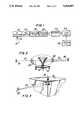
- FIG. 2is a perspective-type illustration of a table-mounted detector according to the present invention.
- FIG. 3is a fragmentary perspective-type illustration of a ceiling-mounted detector according to the present invention.
- FIG. 4is a sectional elevational view of a detector subassembly according to the present invention.
- FIG. 5is a schematic representation illustrating paths of infrared signals being reflected with the present invention.
- infrared signals(shown schematically by phantom lines 12) are received by an infrared detector subassembly 14, also seen in FIG. 4. These signals received by the detector 14 are amplified within pre-amplifier 16 and then successfully amplified and filtered within amplifier/filters 18 and 20 to eliminate lower-than-desired frequencies before being encoded within encoder 22.
- a control signalis produced by a control unit 26 and is sent to a circuit breaker or air gap switch (not shown) which may either break or make the electrical connection within a current-carrying line.
- FIG. 2illustrates in an embodiment of the invention the use of optional lenses 28 which influence infrared signals emanating from bodies 30.
- Lenses 28serve a focusing function, directing signals 12 in substantially parallel directions substantially 90 degrees with respect to an axis 32 referred to in more detail below.
- detector subassembly 14is illustrated in an enlarged view supported upon a piece of room furniture, such as a table 34 which may be substantially centrally located within the room or located at any one of a variety of locations.
- FIG. 3illustrates detector subassembly 14 supported from the ceiling 36 of a room in the line of sight of bodies entering the room.
- FIG. 4 in a sectional elevational viewillustrates detector subassembly 14.
- the reader's attentionis again directed to the similarity of only a portion of subassembly 14 with that shown in U.S. Pat. No. 4,346,427.
- the field of view of the device shown in U.S. Pat. No. 4,346,427is limited by the geometry of its opening to between 90 and 120 degrees, as states in its specification at columns 6 and 7.
- the present inventionthe user enjoys both a 360 degree field of view as well as a field of view in front of the detector, as will become apparent.
- a housing 38 of detector subassembly 14 formed of plasticincludes a base portion 40 formed with a substantially central recess area 42 surrounded by a peripheral seat portion 44 which carries a number of spacers 46 designed to hold in desired position elements of the subassembly, including a circuit board 48.
- a relatively depending neck portion 50surrounds central locator 51 and is formed with external threads 52, which matingly receive internal threads 54 formed within retainer 56.
- Retainer 56is further formed with a central opening in communication with an hermitically sealed sensor 58, including for example a small multijunction thermopile (not seen), of the type available from Dexter Research Center of Dexter, Mich.
- An O-ring 60serves to keep sensor 58 centrally located within neck 50.
- a back plate 62seals the housing base 40 at its top or back.
- a window 66is formed through retainer 56 through which the smaller upper end 68 of a funnel-shaped reflector 70 extends and is held in the position shown in FIG. 4.
- Larger lower end 72 of reflector 70depends from housing 38 such that its curved concave surface of revolution 74 extends about relatively central reflector axis 76.
- reflector 70is further formed with a central opening 78 defined by inner reflecting surfaces 80.
- outer surfaces of revolution 74reflect toward window 66 infrared signals emanating from a body, either with the aid of or without lenses 28.
- Phantom direction lines and arrows 82illustrate paths of such infrared signals which impact outer surface 74
- phantom direction lines and arrows 84illustrate the path of signals which impact inner reflecting surfaces 80.
- FIG. 5is presented to illustrate the variety of angles of incidence of infrared signals which may impact surface 74 in substantially parallel and horizontal paths 90 and which are each reflected to sensor 58 with the aid of surfaces of revolution 70.
- the outer reflective surfaces 74 shown in 5A and 5B for example,are tailored in shape to reflect the infrared signals to their respective sensor 58.
- surface reflectis substantially the locus of points along a parabola.
Landscapes
- Physics & Mathematics (AREA)
- General Physics & Mathematics (AREA)
- Life Sciences & Earth Sciences (AREA)
- General Life Sciences & Earth Sciences (AREA)
- Geophysics (AREA)
- Photometry And Measurement Of Optical Pulse Characteristics (AREA)
- Geophysics And Detection Of Objects (AREA)
Abstract
Description
The present invention relates to the field of infrared radiation as a controlling medium, and more particularly to an improved passive infrared detection and control or switching system.
Infrared systems of various types are known. Examples of issued patents in this area include U.S. Pat. No. 4,346,427, which is improved by the present invention, and U.S. Pat. Nos. 3,439,358; 3,924,130; 3,958,118; 4,029,176; 4,031,408; and 4,196,425, all of which have been cited within aforesaid U.S. Pat. No. 4,346,427 by the U.S. Patent and Trademark Office. Other prior art includes control devices responsive to heat emanating from a human body to provide security-type systems, such as one available from RCA Corporation.
However, a need exists for a system which is capable of better detecting the presence of a body within a predefined area, such as a room within a building. One of the problems with the present state of the art to which the present invention pertains resides with the limited field or angle within which a body may be detected. This limitation is inherent from the structure of the detecting means, which only permits infrared signals from a body to enter the detector within an angle of 180 degrees, for example. Thus, with a prior art detector, more than one such detector is required to provide the detecting coverage enabled by the present invention, thereby increasing the cost and possibly affecting the appearance of the room.
It is an object of the present invention to provide a passive infrared detection system capable of detecting the presence of a body within a range of over 180 degrees about a detector.
It is another object of the present invention to provide such a system, capable of detecting the presence of a body 360 degrees about a detector.
It is a further object of the present invention to provide such a system, wherein the detecting portion includes an annular curved outer reflecting surface extending about a relatively central reflecting axis and is capable of reflecting infrared signals emanating from a body and within parallel paths to a detection signal window lying within a plane at an angle with respect to a central reflecting axis.
It is yet another object of this invention to provide such a system, wherein a detector includes a reflecting surface of revolution.
It is another object of the present invention to provide such a system which is relatively easy to install within an existing room and which operates relatively efficiently.
It is a further object of the invention to provide such a system which is relatively easy to manufacture at a relatively reasonable cost and which is extremely sensitive to the presence of a body.
According to a preferred embodiment of the present invention, and by way of example only, a system for detecting the presence of a body is provided which is capable of installation within a newly constructed or existing room or envelope, wherein a detecting portion of the system includes a reflecting surface capable of reflecting infrared signals received from a body to and through a detection window and to a sensor. This surface is a concave arcuate surface of revolution about a reflecting axis which is able to "capture" signals. The "captured" signals are amplified and converted to a plurality of reset signals. The reset signals have characteristics which, when "disturbed" over a predetermined period of time, enable a control circuit to produce a control signal which, in turn, will switch on a current within a line, thereby causing the lighting of an area (the room) or performing any other desired function in response to the switched on current within the line.
In a preferred embodiment of the invention, a change in the characteristics of the reset signals results from movement of the body within the room or envelope within which the system is situated, and upon a timing circuit failing after a predetermined time period to receive a reference signal characteristic due to such body movement, it cause the control signal to be produced.
The reader will appreciate after a reading of the present specification and said U.S. Pat. No. 4,346,427 that while certain elements of the prior art are combined with the novel detection portion of the present invention, the present system produces a new and novel combination of elements not known to exist heretofore.
A detector housing supports a thermopile in the reflected signal path for receiving the signal through a window, and is adapted to be supported from the center of the ceiling of a room, or the like. The infrared signals emanating from a body are amplified in a plurality of amplifier stages having appropriate filters known to the art for filtering out lower than desired frequency signals. A preamplifier stage is optional, and serves to reduce adverse temperature effects.
Amplified signals are encoded and, after entering the time delay circuitry, enter a control unit for producing a control signal for influencing a current line.
Other objects and features of the present invention will become apparent from a reading of the following specification, drawings and claims, read in conjunction with one another, and wherein:
FIG. 1 is a block diagram illustrating a passive infrared detection system according to the present invention;
FIG. 2 is a perspective-type illustration of a table-mounted detector according to the present invention;
FIG. 3 is a fragmentary perspective-type illustration of a ceiling-mounted detector according to the present invention;
FIG. 4 is a sectional elevational view of a detector subassembly according to the present invention; and
FIG. 5 is a schematic representation illustrating paths of infrared signals being reflected with the present invention.
Referring now to FIG. 1, insystem 10 according to the present invention, infrared signals (shown schematically by phantom lines 12) are received by an infrared detector subassembly 14, also seen in FIG. 4. These signals received by thedetector 14 are amplified within pre-amplifier 16 and then successfully amplified and filtered within amplifier/filters 18 and 20 to eliminate lower-than-desired frequencies before being encoded withinencoder 22. With the aid of a time delay ortiming circuit 24, characteristics of reset signals produced by theencoder 22 are monitored and, upon movement of the body emanating infrared signals, a control signal is produced by acontrol unit 26 and is sent to a circuit breaker or air gap switch (not shown) which may either break or make the electrical connection within a current-carrying line.
FIG. 2 illustrates in an embodiment of the invention the use ofoptional lenses 28 which influence infrared signals emanating frombodies 30.Lenses 28 serve a focusing function, directingsignals 12 in substantially parallel directions substantially 90 degrees with respect to an axis 32 referred to in more detail below. In FIG. 2,detector subassembly 14 is illustrated in an enlarged view supported upon a piece of room furniture, such as a table 34 which may be substantially centrally located within the room or located at any one of a variety of locations. FIG. 3 illustrates detector subassembly 14 supported from the ceiling 36 of a room in the line of sight of bodies entering the room.
FIG. 4 in a sectional elevational view illustrates detector subassembly 14. The reader's attention is again directed to the similarity of only a portion ofsubassembly 14 with that shown in U.S. Pat. No. 4,346,427. However, the significant differences in capability enjoyed by the present invention will be apparent. More specifically, the field of view of the device shown in U.S. Pat. No. 4,346,427 is limited by the geometry of its opening to between 90 and 120 degrees, as states in its specification at columns 6 and 7. With the present invention, the user enjoys both a 360 degree field of view as well as a field of view in front of the detector, as will become apparent.
Ahousing 38 of detector subassembly 14 formed of plastic includes abase portion 40 formed with a substantiallycentral recess area 42 surrounded by aperipheral seat portion 44 which carries a number ofspacers 46 designed to hold in desired position elements of the subassembly, including acircuit board 48. A relatively dependingneck portion 50 surroundscentral locator 51 and is formed withexternal threads 52, which matingly receiveinternal threads 54 formed withinretainer 56.Retainer 56 is further formed with a central opening in communication with an hermitically sealedsensor 58, including for example a small multijunction thermopile (not seen), of the type available from Dexter Research Center of Dexter, Mich. An O-ring 60 serves to keepsensor 58 centrally located withinneck 50. Aback plate 62 seals thehousing base 40 at its top or back.
At the lower orfront end 64 of neck portion 50 awindow 66 is formed throughretainer 56 through which the smaller upper end 68 of a funnel-shaped reflector 70 extends and is held in the position shown in FIG. 4. Largerlower end 72 ofreflector 70 depends fromhousing 38 such that its curved concave surface ofrevolution 74 extends about relativelycentral reflector axis 76. In an optional preferred embodiment of thepresent invention reflector 70 is further formed with a central opening 78 defined by innerreflecting surfaces 80.
In operation, outer surfaces ofrevolution 74 reflect towardwindow 66 infrared signals emanating from a body, either with the aid of or withoutlenses 28. Phantom direction lines andarrows 82 illustrate paths of such infrared signals which impactouter surface 74, while phantom direction lines andarrows 84 illustrate the path of signals which impact inner reflectingsurfaces 80. Thus, the field of view ofdetector subassembly 14 is remarkably large, enabling a far more sensitive detector without sacrificing the ability to filter out undesired signals that might cause false tripping. Whetherdetector subassembly 14 is mounted in a ceiling 36 or a wall is a matter of choice for the user.
FIG. 5 is presented to illustrate the variety of angles of incidence of infrared signals which may impactsurface 74 in substantially parallel andhorizontal paths 90 and which are each reflected tosensor 58 with the aid of surfaces ofrevolution 70. The outerreflective surfaces 74 shown in 5A and 5B for example, are tailored in shape to reflect the infrared signals to theirrespective sensor 58. In one preferred embodiment of the present invention, surface reflect is substantially the locus of points along a parabola.
It is to be understood that the embodiments of the present invention presented and illustrated herein are examples only of the invention, and not by way of limitation, and the scope and spirit of the present invention may be further understood from a reading of the appended claims.
Claims (4)
1. A system for detecting the presence of a body within a predetermined envelope, comprising, in combination:
signal reception means for producing a detection signal in response to detecting an infrared signal from a body, simplifying means for receiving and amplifying said detection signal, said amplifying means comprising an electrical circuit capable of producing a plurality of reset signals, timing means for receiving said reset signals and producing a control signal in response to characteristics of said reset signals, and control means responsive to said control signal for switching current within a line,
said signal reception means including;
an electrical sensor, responsive to infrared, for receiving said infrared signal,
an axis extending from said sensor,
an infrared reflector, having an annular curved outer reflecting surface of revolution extending about said axis, extending along the axis and having an upper end and a lower end, said upper end having a reduced average radius and being closer to the sensor than the lower and,
said curve of said outer reflecting surface curve being for receiving signals directly from said body for reflecting said signals directly to said sensor by means of said annular curved outer reflecting surface,
said annular curved inner reflecting surface extending about said axis, along the axis and having an upper end and a lower end, said upper end having a reduced average radius and being closer to the sensor than the lower end, defining a central detecting opening extending substantially coaxially with respect to said reflecting axis,
said curve of said inner reflecting surface curve being for receiving signals directly from said body for reflecting said signals directly to said sensor by means of said annular curved inner reflecting surface.
2. A system according to claim 1, further comprising:
a lens, positioned between the body and said reflecting surface for focusing said infrared signal before said signal reaches said reflecting surface.
3. A system according to claim 1, further comprising:
a lens, positioned between the body and said outer reflecting surface for focusing said infrared signal before said signal reaches said outer reflecting surface.
4. A system according to claim 1, further comprising:
said central detecting opening further being for receiving signals directly from said body for direct transmission to said sensor without intermediate transmission through a lens.
Priority Applications (2)
| Application Number | Priority Date | Filing Date | Title |
|---|---|---|---|
| US06/916,168US5266807A (en) | 1986-10-10 | 1986-10-10 | Passive infrared detection system |
| CA000534868ACA1337773C (en) | 1986-10-10 | 1987-04-14 | Passive infrared detection system |
Applications Claiming Priority (1)
| Application Number | Priority Date | Filing Date | Title |
|---|---|---|---|
| US06/916,168US5266807A (en) | 1986-10-10 | 1986-10-10 | Passive infrared detection system |
Publications (1)
| Publication Number | Publication Date |
|---|---|
| US5266807Atrue US5266807A (en) | 1993-11-30 |
Family
ID=25436809
Family Applications (1)
| Application Number | Title | Priority Date | Filing Date |
|---|---|---|---|
| US06/916,168Expired - LifetimeUS5266807A (en) | 1986-10-10 | 1986-10-10 | Passive infrared detection system |
Country Status (2)
| Country | Link |
|---|---|
| US (1) | US5266807A (en) |
| CA (1) | CA1337773C (en) |
Cited By (36)
| Publication number | Priority date | Publication date | Assignee | Title |
|---|---|---|---|---|
| US5327048A (en)* | 1993-02-26 | 1994-07-05 | North American Philips Corporation | Bi-level lighting control system for hid lamps |
| US5453622A (en)* | 1993-10-05 | 1995-09-26 | Larry C. Y. Lee | Wide-angle motion detector with close-in, prismoidal reflector |
| US5473311A (en)* | 1994-09-16 | 1995-12-05 | C&K Systems, Inc. | Method and apparatus to distinguish human intruder and animal intruder |
| US5479939A (en)* | 1990-03-09 | 1996-01-02 | Matsushita Electric Industrial Co., Ltd. | Sleep detecting apparatus |
| US5506717A (en)* | 1993-03-03 | 1996-04-09 | Goldstar Co., Ltd. | Apparatus for locating a remote control transmitter |
| US5626417A (en)* | 1996-04-16 | 1997-05-06 | Heath Company | Motion detector assembly for use with a decorative coach lamp |
| EP0772168A3 (en)* | 1995-11-01 | 1997-05-14 | Thomson Consumer Electronics, Inc. | Infrared surveillance system with controlled video recording |
| US5677529A (en)* | 1993-11-06 | 1997-10-14 | Abb Patent Gmbh | Passive infrared sensor using a pair of sensors and reflectors for a 270 degree field of view |
| US5701117A (en)* | 1996-01-18 | 1997-12-23 | Brian Page Platner | Occupancy detector |
| US5764146A (en)* | 1995-03-29 | 1998-06-09 | Hubbell Incorporated | Multifunction occupancy sensor |
| US5772326A (en)* | 1996-08-30 | 1998-06-30 | Hubbell Incorporated | Temperature and passive infrared sensor module |
| US5838238A (en)* | 1996-03-13 | 1998-11-17 | The Johns Hopkins University | Alarm system for blind and visually impaired individuals |
| US5861806A (en)* | 1997-03-19 | 1999-01-19 | James A. Bondell | Occupied room indicator |
| US5929445A (en)* | 1996-09-13 | 1999-07-27 | Electro-Optic Technologies, Llc | Passive infrared detector |
| US5933082A (en)* | 1995-09-26 | 1999-08-03 | The Johns Hopkins University | Passive alarm system for blind and visually impaired individuals |
| US5939987A (en)* | 1998-01-26 | 1999-08-17 | Cram; Randall S. | Roadside deer warning method and system |
| US5973594A (en)* | 1995-03-29 | 1999-10-26 | Hubbell Incorporated | Multiple optical designs for a multifunction sensor |
| US5971597A (en)* | 1995-03-29 | 1999-10-26 | Hubbell Corporation | Multifunction sensor and network sensor system |
| US6215398B1 (en) | 1997-12-18 | 2001-04-10 | Brian P. Platner | Occupancy sensors for long-range sensing within a narrow field of view |
| US6304180B1 (en) | 1998-04-15 | 2001-10-16 | Brian P. Platner | Highly versatile occupancy sensor |
| US6348686B1 (en) | 1999-07-14 | 2002-02-19 | Hubbell Incorporated | Adapter for positioning a lens |
| US6479823B1 (en) | 1999-08-11 | 2002-11-12 | Hubbell Incorporated | Apparatus and method for lens adjustment |
| USD472525S1 (en) | 2001-07-18 | 2003-04-01 | Stephen Barone | Decorative rocker switch |
| US6690018B1 (en) | 1998-10-30 | 2004-02-10 | Electro-Optic Technologies, Llc | Motion detectors and occupancy sensors with improved sensitivity, angular resolution and range |
| US6756595B2 (en) | 2000-09-11 | 2004-06-29 | Electro-Optic Technologies, Llc | Effective quad-detector occupancy sensors and motion detectors |
| USD499703S1 (en) | 2003-06-18 | 2004-12-14 | Electro-Optic Technologies, Llc | Decorative rocker switch |
| US6850159B1 (en) | 2001-05-15 | 2005-02-01 | Brian P. Platner | Self-powered long-life occupancy sensors and sensor circuits |
| USD503387S1 (en) | 2001-07-18 | 2005-03-29 | Electro-Optic Technologies, Llc | Decorative rocker switch |
| USD505119S1 (en) | 1999-10-27 | 2005-05-17 | Electro-Optic Technologies, Llc | Decorative rocker switch |
| US20070030148A1 (en)* | 2005-08-04 | 2007-02-08 | Gekkotek, Llc | Motion-activated switch finder |
| US20070043540A1 (en)* | 2005-06-30 | 2007-02-22 | Cleland Donald A | Adaptive energy performance monitoring and control system |
| US20070177384A1 (en)* | 2006-02-02 | 2007-08-02 | Desa Ip, Llc, A Florida Limited Liability Company | Motion sensing lighting fixture |
| US20090066540A1 (en)* | 2007-09-07 | 2009-03-12 | Dimitri Marinakis | Centralized route calculation for a multi-hop streetlight network |
| US20090066258A1 (en)* | 2007-09-07 | 2009-03-12 | Streetlight Intelligence, Inc. | Streelight monitoring and control |
| US20110057570A1 (en)* | 2005-06-30 | 2011-03-10 | Streetlight Intelligence, Inc. | Method and System for Luminance Characterization |
| CN106644100A (en)* | 2017-02-16 | 2017-05-10 | 东莞传晟光电有限公司 | 360-degree induction pyroelectric infrared sensor |
Citations (4)
| Publication number | Priority date | Publication date | Assignee | Title |
|---|---|---|---|---|
| US3551676A (en)* | 1968-04-19 | 1970-12-29 | Russell W Runnels | Aircraft collision warning system with panoramic viewing reflections |
| US4268752A (en)* | 1979-02-07 | 1981-05-19 | Heimann Gmbh | Optical arrangement for a passive infrared motion detector |
| US4346427A (en)* | 1979-06-29 | 1982-08-24 | Robert Rothenhaus | Control device responsive to infrared radiation |
| US4514630A (en)* | 1981-01-19 | 1985-04-30 | Takenaka Engineering Co., Ltd. | Optical system for intruder detecting device |
- 1986
- 1986-10-10USUS06/916,168patent/US5266807A/ennot_activeExpired - Lifetime
- 1987
- 1987-04-14CACA000534868Apatent/CA1337773C/ennot_activeExpired - Fee Related
Patent Citations (5)
| Publication number | Priority date | Publication date | Assignee | Title |
|---|---|---|---|---|
| US3551676A (en)* | 1968-04-19 | 1970-12-29 | Russell W Runnels | Aircraft collision warning system with panoramic viewing reflections |
| US4268752A (en)* | 1979-02-07 | 1981-05-19 | Heimann Gmbh | Optical arrangement for a passive infrared motion detector |
| US4346427A (en)* | 1979-06-29 | 1982-08-24 | Robert Rothenhaus | Control device responsive to infrared radiation |
| US4346427B1 (en)* | 1979-06-29 | 1987-12-08 | ||
| US4514630A (en)* | 1981-01-19 | 1985-04-30 | Takenaka Engineering Co., Ltd. | Optical system for intruder detecting device |
Cited By (57)
| Publication number | Priority date | Publication date | Assignee | Title |
|---|---|---|---|---|
| US5724990A (en)* | 1990-03-09 | 1998-03-10 | Matsushita Electric Industrial Co., Ltd. | Human monitoring apparatus |
| US5479939A (en)* | 1990-03-09 | 1996-01-02 | Matsushita Electric Industrial Co., Ltd. | Sleep detecting apparatus |
| US5902255A (en)* | 1990-03-09 | 1999-05-11 | Matsushita Electric Industrial Co., Ltd. | Human monitoring device |
| US5327048A (en)* | 1993-02-26 | 1994-07-05 | North American Philips Corporation | Bi-level lighting control system for hid lamps |
| US5506717A (en)* | 1993-03-03 | 1996-04-09 | Goldstar Co., Ltd. | Apparatus for locating a remote control transmitter |
| US5453622A (en)* | 1993-10-05 | 1995-09-26 | Larry C. Y. Lee | Wide-angle motion detector with close-in, prismoidal reflector |
| US5677529A (en)* | 1993-11-06 | 1997-10-14 | Abb Patent Gmbh | Passive infrared sensor using a pair of sensors and reflectors for a 270 degree field of view |
| US5473311A (en)* | 1994-09-16 | 1995-12-05 | C&K Systems, Inc. | Method and apparatus to distinguish human intruder and animal intruder |
| US5971597A (en)* | 1995-03-29 | 1999-10-26 | Hubbell Corporation | Multifunction sensor and network sensor system |
| US6324008B1 (en) | 1995-03-29 | 2001-11-27 | Hubbell Incorporated | Multiple optical designs for a multifunction sensor |
| US5764146A (en)* | 1995-03-29 | 1998-06-09 | Hubbell Incorporated | Multifunction occupancy sensor |
| US5973594A (en)* | 1995-03-29 | 1999-10-26 | Hubbell Incorporated | Multiple optical designs for a multifunction sensor |
| US5933082A (en)* | 1995-09-26 | 1999-08-03 | The Johns Hopkins University | Passive alarm system for blind and visually impaired individuals |
| US5825413A (en)* | 1995-11-01 | 1998-10-20 | Thomson Consumer Electronics, Inc. | Infrared surveillance system with controlled video recording |
| EP0772168A3 (en)* | 1995-11-01 | 1997-05-14 | Thomson Consumer Electronics, Inc. | Infrared surveillance system with controlled video recording |
| US5701117A (en)* | 1996-01-18 | 1997-12-23 | Brian Page Platner | Occupancy detector |
| US5838238A (en)* | 1996-03-13 | 1998-11-17 | The Johns Hopkins University | Alarm system for blind and visually impaired individuals |
| US5626417A (en)* | 1996-04-16 | 1997-05-06 | Heath Company | Motion detector assembly for use with a decorative coach lamp |
| US6082894A (en)* | 1996-08-30 | 2000-07-04 | Hubbell Incorporated | Temperature and passive infrared sensor module |
| US5772326A (en)* | 1996-08-30 | 1998-06-30 | Hubbell Incorporated | Temperature and passive infrared sensor module |
| US5929445A (en)* | 1996-09-13 | 1999-07-27 | Electro-Optic Technologies, Llc | Passive infrared detector |
| US6239437B1 (en) | 1996-09-13 | 2001-05-29 | Electro-Optic Technologies, Llc | Passive infrared detector |
| US6285912B1 (en) | 1996-10-25 | 2001-09-04 | Hubbell Incorporated | System for physically mounting a multifunction user interface to a basic multifunction sensor to access and control various parameters of a control network environment |
| US5861806A (en)* | 1997-03-19 | 1999-01-19 | James A. Bondell | Occupied room indicator |
| US6215398B1 (en) | 1997-12-18 | 2001-04-10 | Brian P. Platner | Occupancy sensors for long-range sensing within a narrow field of view |
| US5939987A (en)* | 1998-01-26 | 1999-08-17 | Cram; Randall S. | Roadside deer warning method and system |
| US6304180B1 (en) | 1998-04-15 | 2001-10-16 | Brian P. Platner | Highly versatile occupancy sensor |
| US20050045826A1 (en)* | 1998-10-30 | 2005-03-03 | Stephen Barone | Motion detectors and occupancy sensors with improved sensitivity, angular resolution and range |
| US7053374B2 (en) | 1998-10-30 | 2006-05-30 | Electro-Optic Technologies, Llc | Motion detectors and occupancy sensors with improved sensitivity, angular resolution and range |
| US6690018B1 (en) | 1998-10-30 | 2004-02-10 | Electro-Optic Technologies, Llc | Motion detectors and occupancy sensors with improved sensitivity, angular resolution and range |
| US6348686B1 (en) | 1999-07-14 | 2002-02-19 | Hubbell Incorporated | Adapter for positioning a lens |
| US6479823B1 (en) | 1999-08-11 | 2002-11-12 | Hubbell Incorporated | Apparatus and method for lens adjustment |
| USD505119S1 (en) | 1999-10-27 | 2005-05-17 | Electro-Optic Technologies, Llc | Decorative rocker switch |
| US6756595B2 (en) | 2000-09-11 | 2004-06-29 | Electro-Optic Technologies, Llc | Effective quad-detector occupancy sensors and motion detectors |
| US6921900B2 (en) | 2000-09-11 | 2005-07-26 | Electro-Optic Technologies, Llc | Effective quad-detector occupancy sensors and motion detectors |
| US7319389B1 (en) | 2001-05-15 | 2008-01-15 | Brian P. Platner | Self-powered long-life occupancy sensors and sensor circuits |
| US6850159B1 (en) | 2001-05-15 | 2005-02-01 | Brian P. Platner | Self-powered long-life occupancy sensors and sensor circuits |
| US7586408B1 (en) | 2001-05-15 | 2009-09-08 | Abl Ip Holding, Llc | Self-powered long-life occupancy sensors and sensor circuits |
| US7576647B1 (en) | 2001-05-15 | 2009-08-18 | Abl Ip Holding, Llc | Self-powered long-life occupancy sensors and sensor circuits |
| USD503387S1 (en) | 2001-07-18 | 2005-03-29 | Electro-Optic Technologies, Llc | Decorative rocker switch |
| USD472525S1 (en) | 2001-07-18 | 2003-04-01 | Stephen Barone | Decorative rocker switch |
| USD499703S1 (en) | 2003-06-18 | 2004-12-14 | Electro-Optic Technologies, Llc | Decorative rocker switch |
| USD502930S1 (en) | 2003-06-18 | 2005-03-15 | Electro-Optic Technologies, Llc | Decorative rocker switch |
| US20070043540A1 (en)* | 2005-06-30 | 2007-02-22 | Cleland Donald A | Adaptive energy performance monitoring and control system |
| US8433426B2 (en) | 2005-06-30 | 2013-04-30 | Led Roadway Lighting Ltd | Adaptive energy performance monitoring and control system |
| US9144135B2 (en) | 2005-06-30 | 2015-09-22 | Led Roadway Lighting Ltd. | Adaptive energy performance monitoring and control system |
| US20110057570A1 (en)* | 2005-06-30 | 2011-03-10 | Streetlight Intelligence, Inc. | Method and System for Luminance Characterization |
| US8264156B2 (en) | 2005-06-30 | 2012-09-11 | Led Roadway Lighting Ltd. | Method and system for luminance characterization |
| US20070030148A1 (en)* | 2005-08-04 | 2007-02-08 | Gekkotek, Llc | Motion-activated switch finder |
| US20070177384A1 (en)* | 2006-02-02 | 2007-08-02 | Desa Ip, Llc, A Florida Limited Liability Company | Motion sensing lighting fixture |
| US20090066540A1 (en)* | 2007-09-07 | 2009-03-12 | Dimitri Marinakis | Centralized route calculation for a multi-hop streetlight network |
| US8290710B2 (en) | 2007-09-07 | 2012-10-16 | Led Roadway Lighting Ltd. | Streetlight monitoring and control |
| US8570190B2 (en) | 2007-09-07 | 2013-10-29 | Led Roadway Lighting Ltd. | Centralized route calculation for a multi-hop streetlight network |
| US8694256B2 (en) | 2007-09-07 | 2014-04-08 | Led Roadway Lighting Ltd. | Streetlight monitoring and control |
| US20090066258A1 (en)* | 2007-09-07 | 2009-03-12 | Streetlight Intelligence, Inc. | Streelight monitoring and control |
| CN106644100A (en)* | 2017-02-16 | 2017-05-10 | 东莞传晟光电有限公司 | 360-degree induction pyroelectric infrared sensor |
| CN106644100B (en)* | 2017-02-16 | 2023-05-23 | 东莞传晟光电有限公司 | 360-degree induction infrared pyroelectric sensor |
Also Published As
| Publication number | Publication date |
|---|---|
| CA1337773C (en) | 1995-12-19 |
Similar Documents
| Publication | Publication Date | Title |
|---|---|---|
| US5266807A (en) | Passive infrared detection system | |
| US4672206A (en) | Passive infrared detector | |
| CA1175525A (en) | Passive infrared intrusion detection system | |
| US5308985A (en) | Wide-angle passive infrared radiation detector | |
| US6087938A (en) | Outdoor intrusion detector | |
| US4636774A (en) | Variable sensitivity motion detector | |
| US4321594A (en) | Passive infrared detector | |
| US3703718A (en) | Infrared intrusion detector system | |
| US9310253B2 (en) | Single technology micro-motion occupancy sensor system | |
| US5227632A (en) | Optical radiation detector with wide field-of-view | |
| CA2265821A1 (en) | Passive infrared detector | |
| GB2059056A (en) | Infrared detection arrangements | |
| US5555454A (en) | Remote security light signal alert system | |
| US5780854A (en) | Structure for an infrared photoelectric device | |
| US4215271A (en) | Adjustable mirror mount for photoelectric intrusion detector | |
| EP0068019B1 (en) | Control device responsive to infrared radiation | |
| US5485011A (en) | Two-sided integrated-circuit PIR sensor package | |
| JPH09230060A (en) | Human body detecting sensor | |
| JPH0612505Y2 (en) | Passive infrared detector | |
| JP2503205B2 (en) | Passive infrared detector | |
| EP1420377A2 (en) | Infrared detector, particularly for outdoor use | |
| JPH0652450A (en) | Heat ray type intrusion detector | |
| AU592526B2 (en) | Non-electronic gain control | |
| WO2000074018A1 (en) | Omni-directional security and lighting system | |
| JPS61126432A (en) | Heat ray type detector |
Legal Events
| Date | Code | Title | Description |
|---|---|---|---|
| AS | Assignment | Owner name:LEVITON MANUFACTURING COMPANY, INC., 59-25 LITTLE Free format text:ASSIGNMENT OF ASSIGNORS INTEREST.;ASSIGNOR:NEIGER, BENJAMIN B.;REEL/FRAME:004699/0288 Effective date:19870227 Owner name:LEVITON MANUFACTURING COMPANY, INC., A NEW YORK C Free format text:ASSIGNMENT OF ASSIGNORS INTEREST;ASSIGNOR:NEIGER, BENJAMIN B.;REEL/FRAME:004699/0288 Effective date:19870227 | |
| STCF | Information on status: patent grant | Free format text:PATENTED CASE | |
| FPAY | Fee payment | Year of fee payment:4 | |
| FPAY | Fee payment | Year of fee payment:8 | |
| FPAY | Fee payment | Year of fee payment:12 | |
| FEPP | Fee payment procedure | Free format text:PAYOR NUMBER ASSIGNED (ORIGINAL EVENT CODE: ASPN); ENTITY STATUS OF PATENT OWNER: LARGE ENTITY Free format text:PAYER NUMBER DE-ASSIGNED (ORIGINAL EVENT CODE: RMPN); ENTITY STATUS OF PATENT OWNER: LARGE ENTITY |