US5266805A - System and method for image recovery - Google Patents
System and method for image recoveryDownload PDFInfo
- Publication number
- US5266805A US5266805AUS07/878,587US87858792AUS5266805AUS 5266805 AUS5266805 AUS 5266805AUS 87858792 AUS87858792 AUS 87858792AUS 5266805 AUS5266805 AUS 5266805A
- Authority
- US
- United States
- Prior art keywords
- infrared
- image
- medium
- imperfections
- energy
- Prior art date
- Legal status (The legal status is an assumption and is not a legal conclusion. Google has not performed a legal analysis and makes no representation as to the accuracy of the status listed.)
- Expired - Lifetime
Links
Images


Classifications
- H—ELECTRICITY
- H04—ELECTRIC COMMUNICATION TECHNIQUE
- H04N—PICTORIAL COMMUNICATION, e.g. TELEVISION
- H04N5/00—Details of television systems
- H04N5/222—Studio circuitry; Studio devices; Studio equipment
- H04N5/253—Picture signal generating by scanning motion picture films or slide opaques, e.g. for telecine
- H—ELECTRICITY
- H04—ELECTRIC COMMUNICATION TECHNIQUE
- H04N—PICTORIAL COMMUNICATION, e.g. TELEVISION
- H04N1/00—Scanning, transmission or reproduction of documents or the like, e.g. facsimile transmission; Details thereof
- H04N1/40—Picture signal circuits
- H04N1/409—Edge or detail enhancement; Noise or error suppression
- H04N1/4097—Removing errors due external factors, e.g. dust, scratches
- H—ELECTRICITY
- H04—ELECTRIC COMMUNICATION TECHNIQUE
- H04N—PICTORIAL COMMUNICATION, e.g. TELEVISION
- H04N3/00—Scanning details of television systems; Combination thereof with generation of supply voltages
- H04N3/36—Scanning of motion picture films, e.g. for telecine
- H—ELECTRICITY
- H04—ELECTRIC COMMUNICATION TECHNIQUE
- H04N—PICTORIAL COMMUNICATION, e.g. TELEVISION
- H04N9/00—Details of colour television systems
- H04N9/11—Scanning of colour motion picture films, e.g. for telecine
Definitions
- This inventionrelates to image enhancement and recovery, and, more particularly to systems and methods which compensate for the effects of storage media defects on images stored therein
- Such systemshave in fact been developed for capturing images of objects along an identical optical path wherein each such image corresponds to a different portion of the electromagnetic spectrum, notably in the satellite photography and reconnaissance arts, for example, for purposes of image enhancement.
- images of one spectrummay thus be superimposed on those from another spectrum of the identical object whereupon various image processing algorithms well known in the art might thereafter be employed.
- an infrared mapping systemmight functionally relate the IR spectrum of carbon dioxide in an earth surface image from that of another portion of the spectrum to draw conclusions regarding surface vegetation or the like as, for example, in crop inventorying and such techniques have been well developed.
- these systemswhile in some sense enhancing the captured image, are not detecting through means of the infrared spectrum defects and imperfections associated with the recording medium itself, and thereafter using such information to enhance the image stored on the medium.
- an object of the inventionis to automatically render invisible or substantially reduce the effect of physical imperfections of the storage medium such as as dust scratches, and the like, from the desired image stored on the film to be perceived. It is a further object of the invention to precisely detect boundaries of recording medium imperfections.
- FIG. 1is an illustration of the separation and recombination of images in different spectra of an object on film having imperfections in order to reduce their effect in the resultant combined image;
- FIG. 2is a schematic representation of a representative system for implementing the invention
- FIG. 3is a functional block diagram of portions of the system of FIG. 2;
- FIG. 4is a flow diagram indicating a sequence of operation of the system of FIG. 2 in accordance with the invention.
- FIG. 5is an illustration of various frequency response signatures associated with aspects of the invention including that of recording media imperfections, a typical array for capturing images from the medium, and that of various dyes associated with the dye-based film-type form of the recording medium;
- FIG. 6is a schematic illustration of image processing steps carried out by the system of FIG. 2 which comprise a portion of the flow diagram of FIG. 4;
- FIG. 7is a schematic illustration of a piece of film containing a defect obscuring an underlying image
- FIGS. 8A and 8Bare additional illustrations of the film of FIG. 7 depicting the results of two respective prior art methods for correcting images having defects caused by recording medium imperfections;
- FIG. 9is another illustration of the film of FIG. 7 depicting results of the invention in correcting the image in FIG. 7 for the defects shown therein.
- a system and method for use in compensating for effects of storage media defects on image data retrieved therefromis stored on a recording medium containing non-image imperfections such as film having surface scratches, waves smudges, bubbles, or the like, which give rise to undesirable artifacts in images subsequently retrieved from the medium.
- Meansare provided for deriving from the medium separate images in the red, green, blue, and infrared portions of the electromagnetic spectrum corresponding to the image stored therein.
- red, green, blue and infrared lightis sequentially directed at one surface of the film by means of a light source and color filter wheel.
- Corresponding sequential red green, blue, and infrared images formed by that portion of the light being transmitted through the filmare digitally captured from the opposite side of the film.
- the imagesare preferably captured in registry to facilitate subtracting out effects of imperfections at locations in the infrared record from corresponding locations in the red, green, blue images.
- the imperffectionsmay either substantially reduce or totally occlude the infrared light.
- remaining portions of the medium having the desired image without such imperfectionsare essentially uniformly transmissive to the infrared spectrum while of variable transmissivity in the visual spectrum as determined by the image developed on the film.
- the infrared imagemay serve s an indicator or map of the spatial position of these non-image imperfections on and in the media, thereby allowing recovery of the underlying desired image.
- the amount of reduction in infrared transmitted through the medium at known locations on the film corresponding to the imperfectionscan be utilized to increase intensity of the red, green, blue images at these same locations so as to cancel the effect of the imperfections.
- the infrared recordprovides an accurate map of the location and shape of the imperfection to which conventional fill-in algorithms are applied.
- film and transparencyare utilized interchangeably and broadly herein and are intended but not to be limited to include any film media for storing images which passes light including negatives as well as positives.
- imperfectionscharacteristically are almost always colorless and thus affect the infrared spectrum equally with the red, green, and blue components of the visible images retained in the film. This is true of various forms of such imperfections. For example, small surface scratches on film are visible because they refract light out of the visual path. This refraction, although very slightly greater for light of short wavelengths, nevertheless is effectively independent of wavelength. Fingerprints and smudges on film are deposits of transparent oils, and again refraction alone makes them visible.
- a "dust" image in the infrared spectrummay be derived from film containing undesired defects and imperfections, and this same image may be applied to red, green, and blue records also obtained from the same portion of film. These imperfections may therefore be seen in the infrared, and this single dust image applied to the three colored red, green and blue records.
- the dust imagemay be applied as hereinafter set forth in greater detail with slightly more strength in the blue record and slightly less strength to the red record in order to compensate for the slight color sensitivity of refraction and defraction.
- the imperfectionmay totally occlude a part of the desired image.
- the inventionat least provides an extremely accurate detection of the exact shape and location of the various imperfections in the film, thereby permitting other fill-in algorithms well known in the art to be employed.
- a significant limitation of those techniqueswas the inability of such algorithms to accurately distinguish imperfections from image detail. Accordingly, image detail was often lost due to the heuristic, subjective identification of the situs of imperfections which was frequently imprecise due to the human intervention.
- the system and method described hereinmay be used in conjunction with such fill-in algorithms to automatically render the imperfection effectively invisible because their locations and boundaries are now more precisely identified without unnecessarily losing image detail.
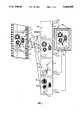
- FIG. 1illustrates the foregoing general principles of the invention just discussed.
- a conventional film transparency 12has one or more frames 10 which include both an image 14 and physical imperfections or defects 16 previously described associated with the film 12, such as dust, scratches, or the like, which impair the ability to retrieve the pure image 14 from the film 12.
- a mechanismsuch as a color wheel or the like (shown conceptually as a prism 18) will be employed to separate the information comprising the image 14 and imperfections 16 into a plurality of individual records, each associated with a different portion of the electromagnetic spectrum. Specifically in sequence infrared 20, red 22, green 24, and blue 26 images of the film 12 are captured.
- the infrared image or record 20a comparison of the pattern of imperfections 16 appearing in the film 12 with those appearing in the infrared record 20 will reveal that they are substantially identical in spatial positioning. As previously indicated, these imperfections 16 associated with film 12 will impede transmissivity of the infrared through the film 12, and thus these imperfections appear at locations 16 on the infrared record 20. It will also be noted in the infrared image 20 that the components comprising the image 14 resulting from various photographic dyes exposed in the film 12 do not appear in the image 20. The reason for this is that, again as previously noted, these dyes are essentially transparent to infrared light transmitted through the film 12.
- each such imagewill be seen to pick up and record portions of the image 14 of the frame 10 associated with their respective visible spectra.
- the green record 24a number of leaves may be seen which in a color illustration would have generally green hues.
- the remaining non-green portions of the image 14are expectedly absent in the green record 24
- the location of imperfections 16 appearing in the red, green, and blue images 22-26will reveal that they again are spatially positioned in the image essentially in identical locations to those in which they appear in the original film 12.
- these imperfections 16appear in each of the red green and blue records, again bearing out the previously described property of such imperfections 16, namely that they are essentially colorless and thus impede transmission of red, green and blue light through the film 12 substantially equally.
- imperfections 16show up as imperfections of equal intensity in the red, green, and blue images (due to the uniform transmissivity of the imperfections 16), given that the precise location of these physical imperfections 16 is known from the infrared record 20 (which includes no information from the desired image 14 to be reproduced), these locations of the imperfections 16 in the infrared record 20 may be utilized to uniformly increase the exposure or intensity of pixels at these same precise locations in the red, green and blue records in a reciprocal way to the infrared intensity to result in the improved image 36.
- red green and blue imagesare recombined (as shown by summing functions 28-32) to result in the image 36, but each such record first has subtracted out (as shown by the subtracting function 34) the intensities at the pixel locations of the imperfections 16 appearing in the infrared record 20 and the corresponding red green, or blue image 22-26.
- FIG. 2a schematic illustration is provided of a representative system for both capturing the necessary four images 20-26 of FIG. 1 from the frame 10 of film 12, and thereafter recombining them as desired in the manner just described to yield an improved image 36.
- the conceptual effect of the prism 18will in the embodiment depicted in FIG. 2 be implemented by means of a color wheel 38 having a plurality of optical filters 40, specifically a red, green, blue and infrared filter.
- a light sourcesuch as a lamp 42 provides light in each of these red, green, blue and infrared spectra
- each of the appropriate color filters 40being sequentially interposed between the film 12 and the lamp 42, light in the red, green, blue and infrared spectra will sequentially be caused to impinge upon and be transmitted through the desired frame 10 of the film 12 in sequence and will thence be captured by an appropriate color camera 42, whereupon the video signal 46 thus generated may be delivered to a suitable computer 48.
- the process of generating sequential color imagesmay of course be automated as shown generally by the control line 44 from the computer 48 to the image generating component of the system of FIG. 2.
- the functions which may be controlled by the computer 48 and control line 44are well known in the art and will thus not be discussed in detail herein. Such functions may include control signals to peripheral devices to sequence advancement of the respective color filters 40 on the color wheel 38, advancement of the film 12 to the desired image 10 and may further include other such controls features as controlling intensity of the lamp 42 for the desired spectral response.
- a keyboard 52provides a conventional user interface to the computer and a color monitor 50 is further provided for viewing the various images as desired.
- the computer 48will in a conventional manner include a system bus 54 for providing intercommunication between a microprocessor 56 within the computer and a program 58 and input/output adapter 60.
- the adapter 60which may take the form of a video capture card is provided in order to interface with the camera 42 and monitor 50 so as to provide proper digitized image data to be stored in and operated upon by the computer 48. Additional adapters may be provided as desired in order to provide further system control and interfacing as for example in provision of the control signals 44 dependent upon the particular system employed.
- the computer 48will desirably include some form of bulk memory capable of storing large amounts of data associated with high resolution digital images such storage being conceptually illustrated in FIG. 3 as the image blocks 62-66.
- Blocks 62 and 64are intended to schematically represent the various red, green, blue and infrared images captured from the frame 10 and stored in the form of digitized pixels in memory.
- the output image box 66is intended to functionally represent the recombined visible image 36 as stored in memory after the computer 48 has operated upon the input images 62 and 64 in accordance with the invention.
- This output image 64may also preferably be in the form of a plurality of digitized image pixels stored in bulk memory in a manner well known in the art.
- the program 58is intended to represent software necessary for controlling the microprocessor 56 and other components of the system in the desired manner to achieve the objectives described herein.
- a component of the program 58may be the control software necessary for generating sequentially the desired red, green, blue and infrared images.
- Microprocessor 56 under the control of this program 58will thus generate the required signals on the system bus 54 transmitted to the input/output adapter or adapters 60 for placing appropriate signals or receiving such signals on the lines 44 and 46 which may include data/address/control signals as necessary.
- an additional component of the program 58will encode the steps necessary to carry out the processing of the images as herein described.
- One representative computerized system for implementing the functions just described relative to FIGS. 2 and 3would include the following components:
- the lamp, filter wheel, film holder, and camera assemblyis contained within a Nikon film scanner model LS 3500.
- the scanneris modified so during the infrared scan the built-in infrared filter is removed, a Kodak Wratten 87C filter inserted in its place, and the voltage on the lamp lowered from the normal 12 volts to 5 volts.
- the computer, display and keyboardcan be one manufactured by International Business Machines containing a GPIB card manufactured by National Instruments of Austin, Tex. to interface to the film scanner.
- the camera 42can be a Pulnix monochrome CCD camera model TM34K specially ordered without the built-in infrared absorbing filter, the colored filters 40 include an 87C for infrared and standard colors for the other positions plus added infrared absorbing filters.
- the arrangement of the wheel, lamp, and film holdershould be obvious to one skilled in the art.
- the pertinent portion of the program 58which accounts for the imperfections 16 and the infrared image 20 in processing the various images to result in the desired recombined image 36 will now be described.
- the image processingwill commence by retrieving pixel data as shown by arrow 68.
- Each pixel digitized and captured from the frame 10will actually include a corresponding red, green, blue and infrared pixel associated with the respective red, green, blue and infrared images 20-26 of FIG. 1.
- These red, green, blue and infrared pixels corresponding to the same location in the frame 10will have intensity values associated therewith which under computer control will be stored and retrieved from memory.
- the associated value of the corresponding infrared pixel 76will be compared to a predetermined threshold value as shown by decision tree 78.
- This threshold valveis selected based on the noise and accuracy of the actual hardware to limit subsequent compensating gain below the point where system noise predominates. This limit is conceptually equivalent to the limit in the automatic gain control (AGC) of a radio receiver.
- AGCautomatic gain control
- this infrared pixeldoes not equal the predetermined value, the pixels associated with this infrared pixel and corresponding location in the frame 10 are considered to be obscured by an imperfection 16 and this fact is recorded with respect to the pixels as shown at block 84.
- An appropriate fill routinemay then be executed by the system of FIG. 2 to replace the respective red, green, blue and infrared pixel values with corrected estimates therefor more accurately reflecting what the values would be if the corresponding imperfections 16 were absent from the film 12.
- Such fill-in routinesare well known in the art and employ various techniques such as examining values of adjacent pixels in order to extrapolate to an estimated value for the obscured pixel as shown at step 86.
- the computer 48will thereafter adjust the corresponding red, green and blue pixel values retrieved in blocks 70-74 by values functionally related to that of the infrared pixel intensity as shown at blocks 90-94. It will be recalled that because the imperfections 16 will essentially due to their uniform transmissivity across the visual spectrum, manifest themselves as dimmed areas perceived in the red, green and blue records, these intensities, must be appropriately intensified so that the areas associated with the imperfections will be in harmony with those of immediately adjacent pixels, thereby reducing the perception of these imperfections in the enhanced image 36. Details of the precise mathematical operation in which the red, green and blue values are "divided" by the infrared value of the corresponding pixel will be hereinafter described in greater detail.
- red, green and blue imagesmay thereafter be selectively recovered on the system bus 54 from memory under control of microprocessor 56 and thereafter output through the I/O adapter 60 in appropriate form whereby they may be combined as, for example, in the monitor 50 so as to display the desired recombined and enhanced image 36 devoid of the deleterious visual affect of the imperfections 16.
- FIG. 5shows the relative absorption of dyes and imperfections such as dust and scratches, and relative sensitivity of image capture sensors and transducers such as charge coupled device (CCD) arrays to various frequencies of light, where the ordinant is the measure of relative percentage of absorption or for the sensor, sensitivity, and the abscissa is the light wavelength in nanometers.
- Dye colorsare labeled with two names, for example "red/cyan" dye is formed by the red sensitive layer to absorb red light therefore appears cyan in color.
- imperfections 16such as dust and the like exhibit substantially uniform absorption of light across the visible range between approximately 400-700 nanometers and into the infrared spectrum from about 700 nanometers on up. Accordingly the graphical depiction of absorption of these imperfections is substantially flat as shown at reference numeral 92. Because the primary effect from most imperfections is refraction, and refraction is slightly less at longer wavelengths, the effect of most imperfections will be slightly less at longer wavelengths, shown in FIG. 5 as a slight tilt to absorption curve 92.
- a more diffuse lightreferred to in microscopy as a light with a larger “numerical aperture”, or NA
- NAthe number of diffuse defects
- the inventionhas particular application in dye-based films.
- unique properties associated with such dyescreate problems which must be accounted for.
- one characteristic of these dyesis that some cyan dyes absorb some infrared.
- Cyan dyes used in positive transparenciesare designed to work with the human visual system, and accordingly are permitted to open up rapidly even in the near infrared, as shown by the positive transparency red/cyan dye response curve 98.
- cyan dyes utilized in negativestypically work with colored paper having a cyan-forming layer sensitive almost into near infrared, and accordingly one must go further into the infrared for these negative cyan dyes to become transparent. This is demonstrated by the spectral response curve of red/cyan dyes utilized for negatives reference numeral 100.
- a light frequency response curve 90 of a charged couple device arraywhich is a typical transducer for capturing light images both in the visible and infrared spectra.
- a charged couple device arraywhich is a typical transducer for capturing light images both in the visible and infrared spectra.
- Such a devicemight typically be found in the camera 42 of FIG. 2 for capturing the red, green, blue and infrared images.
- It will be plainly seen from the spectrum 90there is no problem electronically in "seeing" infrared as the sensitivity of such arrays extend into the infrared spectrum and in fact frequently require eliminating the invisible infrared from a color image.
- CCD sensorsare often more sensitive to infrared than visible light, and thus may adequately be employed to derive the desired infrared image 20 of FIG. 1 when the frame 10 is illuminated with an incandescent form of lamp 42 which puts out most of its radiance in the infrared.
- a problem in implementing the system of FIG. 2might arise if a cold light source is employed exclusively as the lamp 42 or if an infrared absorbing filter is mechanically built into the light sensor of the camera 42, as it would in, for example, in a single chip color CCD array.
- CCD sensorspermit more light piping in the infrared, softening the image and possibly requiring a software boost of high spatial frequencies to renormalize it to the visible acutance.
- Lenses associated with the camera 42also focus differently in the infrared, although this problem may be minimized with apochromats or may be eliminated by simply refocusing slightly, which may even be done through computer control on the I/O control line 44 automatically.
- choosing the wavelength to capture the infrared recordis in itself a compromise as may be understood from the foregoing. If cut too close to the visible spectrum, excessive crossover from the cyan dye record will cause problems in the separation. On the other hand if cut too far into the infrared, the optical problems previously mentioned are made worse. Accordingly, it has been found in practice that a low pass filter below 750 nanometers is a good compromise. The blue sensor will see some of the magenta and cyan record as well as the yellow record it is supposed to see. Similarly, the infrared sensor will see some of the cyan record as well as the "dust" record it is supposed to see.
- the purpose of this figureis to illustrate given the foregoing discussion of non-linearities and the real world, that the image processing, once the red, green and infrared records have been derived, may take a number of forms in co-relating the infrared to the respective red, green and blue records in a manner determined by the particular system being employed and the results desired.
- the inventionadmits to a linear algebra matrix approach in its simplest form but contemplates other processing routines as well.
- the values of individual pixels for each pixel location associated with the frame 10will preferably be operated upon by the system of FIG. 2 and specifically the microprocessor 56.
- Each value of red, green, blue and infrared 102-108 associated with a particular pixelwill in one implementation have the cube root thereof obtained as shown in block 110, whereupon the results will be operated upon by a linear transform 112.
- the reason for the linear transform 112is to simplify the matrix algebra so the calculations may be done faster on a computer.
- the coefficients 113will, in one embodiment, be selected using method of linear algebra to provide independence of all four colors near a selected reference, such as gray.
- the resulting outputs of the transform 112will then be cubed as shown by boxes 114 resulting in red, green, blue and infrared values 116-122, respectively.
- the result for the imperfection or dust record 122 for the particular pixel in questionwill be employed as shown by the divide functional boxes 124 to reduce or divide out the effect of the imperfections in the red, green and blue records.
- the gain of the dust record 122may be adjusted slightly to match the refraction of each color with gamma gain boxes 123. These values are then directly output as R, G, B values 130-134 in the absence of interpolation 126.
- the interpolate box 126receives outputs from divide 124 so that fringe areas of the imperfection that are partially, but not totally occluded may be used in the estimate. This will be covered later in more detail referring to FIGS. 7 and 9.
- the linear matrix 112may not separate perfectly but nevertheless may function sufficiently to achieve effectively perfect separation of the effects of the imperfections 16 if applied in a domain between the linear and logarithmic.
- the cube root domain as shown in FIG. 6has been employed and appears to work quite well.
- the infrared or "dust” recordabsorbs wavelengths so uniformly as to fall into the first case most typically, and thus is best separated from the color records by a linear subtraction in the logarithmic domain. This is precisely a division in the linear domain and as such is shown by division blocks 124 in FIG. 6.
- the dye recordsare subtracted from the dust record in the cube root domain, and then the dust record is divided from the dye records in the linear domain.
- the dust pixel valve 122can be raised to a power "gamma" prior to dividing the red, green, and blue image. Typically the best "gamma" for red is 1.03 for green. 1.06, and for blue, 1.1.
- interpolationmay be used in place of division. It has been found that a pyramid interpolation will in practice remove small imperfections to the point of invisibility. Large imperfections on the other hand may be masked by an algorithm which duplicates texture as well as density across the defect such as a fractal generator. However, employing such a technique may be desirable only in the case of extremely large defects.
- FIGS. 7-9these figures are intended to illustrate comparatively the results of image enhancement employing prior art methods with those of the present invention.
- an identical desired image 136is stored.
- a piece of film 139contains a defect 138 obscuring portions of the desired image 136.
- the defect 138in turn is comprised of a region 142 that only partially obscures the image 136, typically caused by the blurring of the defect lying on the surface of the film out of the image plane or by a soft edge of the defect itself, and may contain a core region 144 that totally obscures the image 136.
- Such defects 138are typically sought to be eliminated in prior art by the process first of detection followed by interpolating in the area detected as being defective based upon adjacent image information in order to mask the defect.
- the results of two prior art methods of attempting to effect correctionsare shown in FIGS. 8A and 8B.
- a human observerwould point to the defect 138 with an airbrush and identify a defective area for example in the shape of a disk 146 of FIG. 8A.
- a benefit of the inventionis achieved by ensuring that the red, green, blue and infrared records are all captured by employing substantially the same optical path, e.g. from the incident light originating from the light source 42 through each selected filter 40, thence through the frame 10 of the film 12 to the camera 42 or other sensor.
- substantially the same optical pathe.g. from the incident light originating from the light source 42 through each selected filter 40, thence through the frame 10 of the film 12 to the camera 42 or other sensor.
- the inventionis not intended to be so limited to collection of light energy transmitted through the medium for which correction of imperfections is desired.
- the inventionadmits to applications wherein, for example, the sensor such as camera 42 is on the same side of the medium as the source of light intended to illuminate the medium 12, whereby the red, green, blue and infrared images may be captured from reflection from the surface of the medium 12.
- the sensor or camera 42may not be in coaxial alignment with the medium 12 and light source 42 as in the case of the system of FIG. 2 but rather may be off to one side of the light source.
- the medium 12would still be desirable to illuminate the medium 12 with various light frequencies such as by laser illumination, gas discharge, LED (light emitting diode) or with the previously described color filters so that the red, green and blue and infrared images would then be gathered by light travelling along essentially the same optical path for each group of such images for the noted reason of facilitating registry of image and defect refraction and subsequent processing of the red, green, blue and infrared pixels of the corresponding red, green, blue and infrared images associated with a particular location on the medium 12.
- various light frequenciessuch as by laser illumination, gas discharge, LED (light emitting diode) or with the previously described color filters so that the red, green and blue and infrared images would then be gathered by light travelling along essentially the same optical path for each group of such images for the noted reason of facilitating registry of image and defect refraction and subsequent processing of the red, green, blue and infrared pixels of the corresponding red, green, blue and infrared images associated with a particular location on the medium 12.
- the preferred embodimenthas described sequential capture of red, green, blue and infrared. It should be obvious that one could obtain the four images simultaneously using white light containing all colors by extending standard 3-color camera technologies to 4-colors. An example of this would be to use a 4 line CCD sensor with filters built over the lines to pass separately red, green, blue, and infrared, or a 4-chip camera using dichromic mirrors to separate red, green, blue, and infrared images separately on the 4 chips.
- any of the elements used to recover the image without defectsmay be implemented in analog circuitry or by using an analog-to-digital converter with digital hardware, or even with software running on a computer or a digital signal processor (DSP). Also the several elements, such as capturing the red, green, blue, and infrared images, and processing the results, can be done serially or in parallel. Although the discussion has assumed serial capture of images to a computer memory for processing, in certain fields other structures are preferred.
- a color camera with a fourth infrared sensoroutputs the red, green, blue, and infrared signals to analog circuitry that substantially divides the red, green, and blue by the infrared providing in real time removal of scratches, dust, fungus growth, fingerprints, transparent-type splices, and other imperfections.
- analog circuitrythat substantially divides the red, green, and blue by the infrared providing in real time removal of scratches, dust, fungus growth, fingerprints, transparent-type splices, and other imperfections.
Landscapes
- Engineering & Computer Science (AREA)
- Multimedia (AREA)
- Signal Processing (AREA)
- Facsimile Scanning Arrangements (AREA)
- Investigating Materials By The Use Of Optical Means Adapted For Particular Applications (AREA)
- Apparatus For Radiation Diagnosis (AREA)
- Image Processing (AREA)
- Image Input (AREA)
- Ultra Sonic Daignosis Equipment (AREA)
- Facsimiles In General (AREA)
- Color Television Image Signal Generators (AREA)
- Facsimile Image Signal Circuits (AREA)
- Separation, Recovery Or Treatment Of Waste Materials Containing Plastics (AREA)
Abstract
Description
Claims (41)
Priority Applications (7)
| Application Number | Priority Date | Filing Date | Title |
|---|---|---|---|
| US07/878,587US5266805A (en) | 1992-05-05 | 1992-05-05 | System and method for image recovery |
| CA002091081ACA2091081C (en) | 1992-05-05 | 1993-03-05 | System and method for image recovery |
| JP5077867AJP2559970B2 (en) | 1992-05-05 | 1993-04-05 | Method and apparatus for compensating the effects of storage medium defects |
| AT93302897TATE172070T1 (en) | 1992-05-05 | 1993-04-14 | DEVICE AND METHOD FOR IMAGE RECOVERY |
| SG1996000328ASG43734A1 (en) | 1992-05-05 | 1993-04-14 | System and method for image recovery |
| DE69321390TDE69321390T2 (en) | 1992-05-05 | 1993-04-14 | Device and method for image recovery |
| EP93302897AEP0569142B1 (en) | 1992-05-05 | 1993-04-14 | System and method for image recovery |
Applications Claiming Priority (1)
| Application Number | Priority Date | Filing Date | Title |
|---|---|---|---|
| US07/878,587US5266805A (en) | 1992-05-05 | 1992-05-05 | System and method for image recovery |
Publications (1)
| Publication Number | Publication Date |
|---|---|
| US5266805Atrue US5266805A (en) | 1993-11-30 |
Family
ID=25372337
Family Applications (1)
| Application Number | Title | Priority Date | Filing Date |
|---|---|---|---|
| US07/878,587Expired - LifetimeUS5266805A (en) | 1992-05-05 | 1992-05-05 | System and method for image recovery |
Country Status (7)
| Country | Link |
|---|---|
| US (1) | US5266805A (en) |
| EP (1) | EP0569142B1 (en) |
| JP (1) | JP2559970B2 (en) |
| AT (1) | ATE172070T1 (en) |
| CA (1) | CA2091081C (en) |
| DE (1) | DE69321390T2 (en) |
| SG (1) | SG43734A1 (en) |
Cited By (138)
| Publication number | Priority date | Publication date | Assignee | Title |
|---|---|---|---|---|
| US5371542A (en)* | 1992-06-23 | 1994-12-06 | The United States Of America As Represented By The Secretary Of The Navy | Dual waveband signal processing system |
| EP0690608A2 (en) | 1994-06-30 | 1996-01-03 | International Business Machines Corporation | Film scanning system and method |
| US5550566A (en)* | 1993-07-15 | 1996-08-27 | Media Vision, Inc. | Video capture expansion card |
| US5602939A (en)* | 1993-01-28 | 1997-02-11 | Richo Company, Ltd. | Specific document discriminating apparatus and image reading apparatus using it therein |
| US5606630A (en)* | 1992-12-28 | 1997-02-25 | Minolta Camera Kabushiki Kaisha | Photographed image reproducing apparatus |
| US5606379A (en)* | 1996-04-10 | 1997-02-25 | Eastman Kodak Company | Method for recording and storing color images |
| US5731880A (en)* | 1993-01-19 | 1998-03-24 | Canon Kabushiki Kaisha | Image processing apparatus for discriminating an original having a predetermined pattern |
| US5808669A (en)* | 1995-02-07 | 1998-09-15 | Adaptive Optics Associates, Inc. | Telecine with dual digitizers and multiple scanning beams |
| WO1998034397A3 (en)* | 1997-01-30 | 1998-11-19 | Applied Science Fiction Inc | Four color trilinear ccd scanning |
| US5852502A (en)* | 1996-05-31 | 1998-12-22 | American Digital Imaging, Inc. | Apparatus and method for digital camera and recorder having a high resolution color composite image output |
| US5896468A (en)* | 1995-11-27 | 1999-04-20 | Nortrhop Grumman Corporation | Heuristic smoothing filter for digital maps |
| US5923042A (en)* | 1994-10-11 | 1999-07-13 | International Business Machines Corporation | Method and apparatus for optically scanning transparent media |
| WO1999046729A1 (en)* | 1998-03-13 | 1999-09-16 | Applied Science Fiction, Inc. | Image defect correction method |
| US5969372A (en)* | 1997-10-14 | 1999-10-19 | Hewlett-Packard Company | Film scanner with dust and scratch correction by use of dark-field illumination |
| US6075590A (en)* | 1998-03-02 | 2000-06-13 | Applied Science Fiction, Inc. | Reflection infrared surface defect correction |
| US6078051A (en)* | 1998-01-08 | 2000-06-20 | Xerox Corporation | Image input device and method for providing scanning artifact detection |
| DE10029826C1 (en)* | 2000-06-16 | 2001-08-02 | Agfa Gevaert Ag | Method and device for defect detection and / or correction in digital image processing |
| US20010021034A1 (en)* | 1999-02-25 | 2001-09-13 | Hiroyuki Suzuki | Image processing apparatus and method |
| US20010036296A1 (en)* | 1999-12-30 | 2001-11-01 | Young Robert S. | Digital film processing feature location method and system |
| US20010041018A1 (en)* | 2000-01-31 | 2001-11-15 | Fumihiro Sonoda | Image processing method |
| US6323967B1 (en) | 1997-05-16 | 2001-11-27 | Nikon Corporation | Illumination device and image reading apparatus |
| US6327056B1 (en)* | 1999-01-29 | 2001-12-04 | Microtek International Inc. | Image scanner with image correction function |
| US20010052992A1 (en)* | 2000-06-15 | 2001-12-20 | Fuji Photo Film Co., Ltd. | Image correction apparatus |
| DE10041751A1 (en)* | 2000-08-25 | 2002-03-14 | Agfa Gevaert Ag | Method for correction of defects and flaws during digital image processing, involves correcting image on basis of error image depending on spectral range of image |
| DE10041750A1 (en)* | 2000-08-25 | 2002-03-14 | Agfa Gevaert Ag | On-light or transmitted-light scanners and image processing methods for scanned image originals |
| US20020033975A1 (en)* | 1999-12-02 | 2002-03-21 | Yoshiro Yamazaki | Image reading apparatus and method |
| US6369873B1 (en) | 2000-06-13 | 2002-04-09 | Eastman Kodak Company | Thermal processing system and method including a kiosk |
| US6404516B1 (en) | 1999-02-22 | 2002-06-11 | Applied Science Fiction, Inc. | Parametric image stitching |
| US20020080409A1 (en)* | 1999-12-31 | 2002-06-27 | Keyes Michael P. | Digital film processing method |
| US20020106134A1 (en)* | 2000-09-22 | 2002-08-08 | Dundon Thomas A. | Multiple-orientation image defect detection and correction |
| US6437358B1 (en) | 1999-02-04 | 2002-08-20 | Applied Science Fiction, Inc. | Apparatus and methods for capturing defect data |
| US6439784B1 (en) | 1999-08-17 | 2002-08-27 | Applied Science Fiction, Inc. | Method and system for using calibration patches in electronic film processing |
| US6442301B1 (en) | 1997-01-06 | 2002-08-27 | Applied Science Fiction, Inc. | Apparatus and method for defect channel nulling |
| US6443639B1 (en) | 1999-06-29 | 2002-09-03 | Applied Science Fiction, Inc. | Slot coater device for applying developer to film for electronic film development |
| US6447178B2 (en) | 1999-12-30 | 2002-09-10 | Applied Science Fiction, Inc. | System, method, and apparatus for providing multiple extrusion widths |
| US20020130958A1 (en)* | 2001-02-24 | 2002-09-19 | Brad Simon | Method and apparatus for eliminating unwanted portions of photographic images |
| US20020131649A1 (en)* | 2001-03-19 | 2002-09-19 | Hiroshi Yamaguchi | Image processing device and method, and recording medium |
| US6461061B2 (en) | 1999-12-30 | 2002-10-08 | Applied Science Fiction, Inc. | System and method for digital film development using visible light |
| US6465801B1 (en) | 2000-07-31 | 2002-10-15 | Hewlett-Packard Company | Dust and scratch detection for an image scanner |
| US20020149771A1 (en)* | 2001-04-17 | 2002-10-17 | Fuji Photo Film Co., Ltd. | Apparatus and method for inspecting light transmittable material |
| US20020159165A1 (en)* | 2000-09-22 | 2002-10-31 | Ford Gordon D. | Lens focusing device, system and method for use with multiple light wavelengths |
| US6475711B1 (en) | 1999-12-31 | 2002-11-05 | Applied Science Fiction, Inc. | Photographic element and digital film processing method using same |
| US6487321B1 (en) | 1999-09-16 | 2002-11-26 | Applied Science Fiction | Method and system for altering defects in a digital image |
| US20020181759A1 (en)* | 2001-05-29 | 2002-12-05 | Fuji Photo Film Co., Ltd. | Image reading apparatus |
| US6493115B1 (en)* | 1994-11-18 | 2002-12-10 | Canon Kabushiki Kaisha | Image processing apparatus for processing a document image in accordance with an area specified by a marker marked on the document |
| US6498867B1 (en) | 1999-10-08 | 2002-12-24 | Applied Science Fiction Inc. | Method and apparatus for differential illumination image-capturing and defect handling |
| US6503002B1 (en) | 1996-12-05 | 2003-01-07 | Applied Science Fiction, Inc. | Method and apparatus for reducing noise in electronic film development |
| US6505977B2 (en) | 1999-12-30 | 2003-01-14 | Applied Science Fiction, Inc. | System and method for digital color dye film processing |
| US20030011827A1 (en)* | 1999-12-29 | 2003-01-16 | Applied Science Fiction | Distinguishing positive and negative films system and method |
| US6512601B1 (en) | 1998-02-23 | 2003-01-28 | Applied Science Fiction, Inc. | Progressive area scan in electronic film development |
| US20030048453A1 (en)* | 2001-09-12 | 2003-03-13 | Fuji Photo Film Co., Ltd. | Sensor utilizing attenuated total reflection |
| US6540416B2 (en) | 1999-12-30 | 2003-04-01 | Applied Science Fiction, Inc. | System and method for digital film development using visible light |
| US20030072501A1 (en)* | 2001-09-27 | 2003-04-17 | Fuji Photo Film Co., Ltd. | Image processing apparatus |
| US6552778B1 (en)* | 1999-08-02 | 2003-04-22 | Fuji Photo Film Co., Ltd. | Image reading device |
| US6554504B2 (en) | 1999-12-30 | 2003-04-29 | Applied Science Fiction, Inc. | Distributed digital film processing system and method |
| US6558052B2 (en) | 1997-01-30 | 2003-05-06 | Applied Science Fiction, Inc. | System and method for latent film recovery in electronic film development |
| US20030095293A1 (en)* | 1999-12-08 | 2003-05-22 | Hiroyuki Wada | Image reading method and apparatus, and storage medium |
| US20030118249A1 (en)* | 2001-04-19 | 2003-06-26 | Edgar Albert D. | Method, system and software for correcting image defects |
| US6590679B1 (en)* | 1998-02-04 | 2003-07-08 | Applied Science Fiction, Inc. | Multilinear array sensor with an infrared line |
| US6594041B1 (en) | 1998-11-20 | 2003-07-15 | Applied Science Fiction, Inc. | Log time processing and stitching system |
| US6593558B1 (en) | 1996-05-10 | 2003-07-15 | Applied Science Fiction, Inc. | Luminance-priority electronic color image sensor |
| US6599036B2 (en) | 2000-02-03 | 2003-07-29 | Applied Science Fiction, Inc. | Film processing solution cartridge and method for developing and digitizing film |
| US20030150918A1 (en)* | 2002-02-08 | 2003-08-14 | Ryuji Nogami | Illumination apparatus and image reading apparatus |
| US6614946B1 (en) | 1999-10-08 | 2003-09-02 | Eastman Kodak Company | System and method for correcting defects in digital images through selective fill-in from surrounding areas |
| US20030168601A1 (en)* | 2002-03-04 | 2003-09-11 | Koji Kita | Image processing method, image processing program and image processing apparatus |
| US6619863B2 (en) | 2000-02-03 | 2003-09-16 | Eastman Kodak Company | Method and system for capturing film images |
| US20030178555A1 (en)* | 2000-06-20 | 2003-09-25 | Umax Data Systems Inc. | Filtering method and mechanism for scanners |
| US6657663B2 (en)* | 1998-05-06 | 2003-12-02 | Intel Corporation | Pre-subtracting architecture for enabling multiple spectrum image sensing |
| US6660987B2 (en)* | 2000-04-13 | 2003-12-09 | Canon Kabushiki Kaisha | Image reading apparatus and illumination apparatus |
| EP1081938A3 (en)* | 1999-09-02 | 2003-12-17 | Eastman Kodak Company | Scanner with automatic detection of film type |
| US6683995B2 (en) | 1999-12-23 | 2004-01-27 | Eastman Kodak Company | Method and apparatus for correcting large defects in digital images |
| US20040027618A1 (en)* | 2002-06-03 | 2004-02-12 | Fuji Photo Film Co., Ltd. | Image defect detecting method |
| US6704458B2 (en) | 1999-12-29 | 2004-03-09 | Eastman Kodak Company | Method and apparatus for correcting heavily damaged images |
| US6707557B2 (en) | 1999-12-30 | 2004-03-16 | Eastman Kodak Company | Method and system for estimating sensor dark current drift and sensor/illumination non-uniformities |
| US6710329B1 (en) | 2002-09-12 | 2004-03-23 | Eastman Kodak Company | Light integrator for film scanning with enhanced suppression of artifacts due to scratches and debris |
| US6711302B1 (en) | 1999-10-20 | 2004-03-23 | Eastman Kodak Company | Method and system for altering defects in digital image |
| US6720560B1 (en) | 1999-12-30 | 2004-04-13 | Eastman Kodak Company | Method and apparatus for scanning images |
| US20040076337A1 (en)* | 2002-09-05 | 2004-04-22 | Hirobumi Nishida | Image processing device estimating black character color and ground color according to character-area pixels classified into two classes |
| US6733960B2 (en) | 2001-02-09 | 2004-05-11 | Eastman Kodak Company | Digital film processing solutions and method of digital film processing |
| US20040120014A1 (en)* | 2002-12-11 | 2004-06-24 | Konica Minolta Holdings, Inc. | Image-processing apparatus, image-processing method, image-processing program and image-recording apparatus |
| US6775419B2 (en) | 1997-07-24 | 2004-08-10 | Nikon Corporation | Image processing method, image processing apparatus, and storage medium for storing control process |
| US6781724B1 (en) | 2000-06-13 | 2004-08-24 | Eastman Kodak Company | Image processing and manipulation system |
| US6781620B1 (en) | 1999-03-16 | 2004-08-24 | Eastman Kodak Company | Mixed-element stitching and noise reduction system |
| US20040169126A1 (en)* | 1999-03-15 | 2004-09-02 | Nikon Corporation | Image reading device, method and program using infrared light detection to correct for defective pixels |
| US6786655B2 (en) | 2000-02-03 | 2004-09-07 | Eastman Kodak Company | Method and system for self-service film processing |
| US6788335B2 (en) | 1999-12-30 | 2004-09-07 | Eastman Kodak Company | Pulsed illumination signal modulation control & adjustment method and system |
| US6805501B2 (en) | 2001-07-16 | 2004-10-19 | Eastman Kodak Company | System and method for digital film development using visible light |
| US6813392B2 (en) | 1999-12-30 | 2004-11-02 | Eastman Kodak Company | Method and apparatus for aligning multiple scans of the same area of a medium using mathematical correlation |
| US20040240751A1 (en)* | 2003-02-28 | 2004-12-02 | Koji Kita | Image processing method and apparatus for recovering reading faults |
| US6832008B1 (en) | 1998-09-25 | 2004-12-14 | Canon Kabushiki Kaisha | Image reading apparatus and method, and storage medium |
| US6862117B1 (en) | 1999-12-30 | 2005-03-01 | Eastman Kodak Company | Method and apparatus for reducing the effect of bleed-through on captured images |
| US20050047658A1 (en)* | 2003-08-29 | 2005-03-03 | Koji Kita | Image processing apparatus and image processing method |
| US6864973B2 (en) | 1999-12-30 | 2005-03-08 | Eastman Kodak Company | Method and apparatus to pre-scan and pre-treat film for improved digital film processing handling |
| US20050058362A1 (en)* | 2003-09-17 | 2005-03-17 | Koji Kita | Image processing apparatus, image processing method and program |
| US20050058366A1 (en)* | 2003-09-11 | 2005-03-17 | Yan-Ru Jiang | Method of reparing scratches in digital images |
| US20050063026A1 (en)* | 2003-09-24 | 2005-03-24 | Eastman Kodak Company | Calibration arrangement for a scanner |
| US20050083557A1 (en)* | 1998-09-17 | 2005-04-21 | Masatoshi Nagano | Image scanning apparatus and method, and storage medium |
| US6888997B2 (en) | 2000-12-05 | 2005-05-03 | Eastman Kodak Company | Waveguide device and optical transfer system for directing light to an image plane |
| US6915021B2 (en) | 1999-12-17 | 2005-07-05 | Eastman Kodak Company | Method and system for selective enhancement of image data |
| US6924911B1 (en) | 1999-10-12 | 2005-08-02 | Eastman Kodak Company | Method and system for multi-sensor signal detection |
| US20050195297A1 (en)* | 2004-03-03 | 2005-09-08 | Koji Kita | Image processing apparatus and image processing method for correcting image data |
| US6943920B2 (en) | 2000-02-03 | 2005-09-13 | Eastman Kodak Company | Method, system, and software for signal processing using pyramidal decomposition |
| US6950608B2 (en) | 2003-12-23 | 2005-09-27 | Eastman Kodak Company | Capture of multiple interlaced images on a single film frame using micro-lenses and method of providing multiple images to customers |
| US20050213838A1 (en)* | 2004-03-25 | 2005-09-29 | Noritsu Koki Co., Ltd. | Defective pixel correcting method, software and image processing system for implementing the method |
| US20050237392A1 (en)* | 2004-04-26 | 2005-10-27 | Casio Computer Co., Ltd. | Optimal-state image pickup camera |
| US6965692B1 (en) | 1999-12-30 | 2005-11-15 | Eastman Kodak Company | Method and apparatus for improving the quality of reconstructed information |
| US20050254097A1 (en)* | 2004-05-14 | 2005-11-17 | Xerox Corporation | Systems and methods for streak detection in image array scanning using overdetermined scanners and column filtering |
| US6972877B1 (en)* | 1999-06-30 | 2005-12-06 | Fuji Photo Film Co., Ltd. | Image reading apparatus |
| US6990251B2 (en) | 2000-02-03 | 2006-01-24 | Eastman Kodak Company | Method, system, and software for signal processing using sheep and shepherd artifacts |
| US7016080B2 (en) | 2000-09-21 | 2006-03-21 | Eastman Kodak Company | Method and system for improving scanned image detail |
| US7020344B2 (en) | 2000-02-03 | 2006-03-28 | Eastman Kodak Company | Match blur system and method |
| US20060115177A1 (en)* | 2002-12-27 | 2006-06-01 | Nikon Corporation | Image processing device and image processing program |
| US7061000B2 (en) | 2001-03-30 | 2006-06-13 | Fuji Photo Film Co., Ltd. | Image processing apparatus for detecting and correcting defects |
| US20060182337A1 (en)* | 2000-06-28 | 2006-08-17 | Ford Benjamin C | Method and apparatus for improving the quality of reconstructed information |
| US7113619B1 (en) | 1999-09-07 | 2006-09-26 | Fuji Photo Film Co., Ltd. | Image reading method, image reading apparatus and method of discriminating defect of image data |
| US7183532B2 (en) | 2001-04-30 | 2007-02-27 | Hewlett-Packard Development Company, L.P. | Detecting a defect in an image scanner |
| US20070109605A1 (en)* | 2005-11-16 | 2007-05-17 | Fuji Xerox Co., Ltd. | Image reading device and noise detecting method |
| US20070189636A1 (en)* | 2000-06-19 | 2007-08-16 | Tsutomu Takayama | Signal processing method, signal processing apparatus, and image reading apparatus |
| US7263240B2 (en) | 2002-01-14 | 2007-08-28 | Eastman Kodak Company | Method, system, and software for improving signal quality using pyramidal decomposition |
| WO2008057747A1 (en)* | 2006-10-27 | 2008-05-15 | Hewlett-Packard Development Company, L.P. | Transparency template with fiducial marks for aligning multiple scans used for removal of scratches and other imperfections |
| US20080170800A1 (en)* | 2007-01-16 | 2008-07-17 | Ruth Bergman | One-pass filtering and infrared-visible light decorrelation to reduce noise and distortions |
| US20080170801A1 (en)* | 2005-09-05 | 2008-07-17 | Algosoft Limited | Automatic digital film and video restoration |
| US7408569B1 (en)* | 1999-09-06 | 2008-08-05 | Fujifilm Corporation | Image processing device, image processing method and recording medium |
| US20080195456A1 (en)* | 2006-09-28 | 2008-08-14 | Dudley Fitzpatrick | Apparatuses, Methods and Systems for Coordinating Personnel Based on Profiles |
| US20080224043A1 (en)* | 2007-03-16 | 2008-09-18 | David Troy Roberts | Artifact scanning with infrared radiation generated within a cold cathode lamp |
| US20090073262A1 (en)* | 2007-09-13 | 2009-03-19 | Gabriel Fielding | Method for infrared image correction and enhancement |
| US20100201869A1 (en)* | 2009-02-12 | 2010-08-12 | Samsung Electronics Co., Ltd. | Image processing methods, apparatus and computer program products using interdependent pixel interpolation operations |
| US20100306318A1 (en)* | 2006-09-28 | 2010-12-02 | Sfgt Inc. | Apparatuses, methods, and systems for a graphical code-serving interface |
| US20100322492A1 (en)* | 2009-06-17 | 2010-12-23 | Herbert Stepp | Apparatus And Method For Controlling A Multi-Color Output Of An Image Of A Medical Object |
| US20110233432A1 (en)* | 2010-03-25 | 2011-09-29 | Mitsubishi Electric Corporation | Image reader |
| EP1244286B1 (en)* | 2001-03-15 | 2012-05-30 | Canon Kabushiki Kaisha | Image reading apparatus and illumination apparatus |
| US9390309B2 (en) | 2010-11-03 | 2016-07-12 | Lockheed Martin Corporation | Latent fingerprint detectors and fingerprint scanners therefrom |
| US9804096B1 (en) | 2015-01-14 | 2017-10-31 | Leidos Innovations Technology, Inc. | System and method for detecting latent images on a thermal dye printer film |
| US9897544B2 (en) | 2011-08-26 | 2018-02-20 | Lockheed Martin Corporation | Latent fingerprint detection |
| CN109919995A (en)* | 2019-01-31 | 2019-06-21 | 交通运输部天津水运工程科学研究所 | A method of visual auditing of greening works |
| US10387998B2 (en)* | 2017-06-09 | 2019-08-20 | Fuji Xerox Co., Ltd. | Electronic apparatus and non-transitory computer readable medium storing program |
| US20200045185A1 (en)* | 2018-07-31 | 2020-02-06 | Taku Kodama | Image data generation apparatus, information processing system, image data generation method, and recording medium |
| CN116626053A (en)* | 2023-07-24 | 2023-08-22 | 宁德微图智能科技有限公司 | Cell blue film defect detection method and device |
Families Citing this family (11)
| Publication number | Priority date | Publication date | Assignee | Title |
|---|---|---|---|---|
| US5509086A (en)* | 1993-12-23 | 1996-04-16 | International Business Machines Corporation | Automatic cross color elimination |
| GB2286309B (en)* | 1994-02-01 | 1998-04-15 | Rank Cintel Ltd | High resolution film scanner |
| EP0893914A3 (en) | 1997-07-24 | 2002-01-02 | Nikon Corporation | Image processing method, image processing apparatus, and storage medium for storing control process |
| JPH11143031A (en)* | 1997-11-11 | 1999-05-28 | Konica Corp | Visible image output method using non-visible image information and visible image forming method |
| US6792162B1 (en)* | 1999-08-20 | 2004-09-14 | Eastman Kodak Company | Method and apparatus to automatically enhance the quality of digital images by measuring grain trace magnitudes |
| JP2003075922A (en) | 2001-09-04 | 2003-03-12 | Konica Corp | Image forming method and apparatus for silver halide color photographic sensitive material |
| US7209599B2 (en) | 2002-07-12 | 2007-04-24 | Hewlett-Packard Development Company, L.P. | System and method for scanned image bleedthrough processing |
| GB0316994D0 (en) | 2003-07-21 | 2003-08-27 | E2V Tech Uk Ltd | Smear reduction in CCD images |
| JP4117556B2 (en)* | 2003-09-08 | 2008-07-16 | ノーリツ鋼機株式会社 | Film image processing apparatus and film image processing method |
| DE102008027653B4 (en)* | 2008-06-10 | 2012-11-08 | Basler Ag | Method for increasing the contrast |
| JP7198166B2 (en)* | 2019-06-27 | 2022-12-28 | 株式会社日立ハイテク | Ion source abnormality detector and mass spectrometer using the same |
Citations (6)
| Publication number | Priority date | Publication date | Assignee | Title |
|---|---|---|---|---|
| US3715962A (en)* | 1970-04-20 | 1973-02-13 | Spectral Data Corp | Spectral-zonal color reconnaissance system |
| SU574693A1 (en)* | 1976-05-18 | 1977-09-30 | Предприятие П/Я Р-6681 | Spectrozonal camera |
| US4160601A (en)* | 1978-02-24 | 1979-07-10 | Nasa | Biocontamination and particulate detection system |
| JPS60115820A (en)* | 1983-11-29 | 1985-06-22 | Tatsuro Kunishi | Method for extracting and measuring black plate component of multicolor printed matter |
| US4683496A (en)* | 1985-08-23 | 1987-07-28 | The Analytic Sciences Corporation | System for and method of enhancing images using multiband information |
| US5151596A (en)* | 1990-03-28 | 1992-09-29 | Fuji Photo Film Co., Ltd. | Method and apparatus for detecting the location of a pattern in a radiation image stored on a stimulable phosphor sheet |
Family Cites Families (5)
| Publication number | Priority date | Publication date | Assignee | Title |
|---|---|---|---|---|
| GB1547812A (en)* | 1977-04-27 | 1979-06-27 | British Broadcasting Corp | Telecine machines |
| EP0101180B1 (en)* | 1982-07-16 | 1988-10-05 | British Broadcasting Corporation | Concealment of defects in a video signal |
| DE3318216C2 (en)* | 1983-05-19 | 1987-01-08 | Robert Bosch Gmbh, 7000 Stuttgart | Television film scanner |
| US4878109A (en)* | 1986-04-01 | 1989-10-31 | Thinking Machines Corporation | Unsynchronized multispectral video filtering system with filter identification sensor within field of view and video signal responsive |
| JPH0797402B2 (en)* | 1986-11-19 | 1995-10-18 | キヤノン株式会社 | Image correction method |
- 1992
- 1992-05-05USUS07/878,587patent/US5266805A/ennot_activeExpired - Lifetime
- 1993
- 1993-03-05CACA002091081Apatent/CA2091081C/ennot_activeExpired - Lifetime
- 1993-04-05JPJP5077867Apatent/JP2559970B2/ennot_activeExpired - Lifetime
- 1993-04-14ATAT93302897Tpatent/ATE172070T1/ennot_activeIP Right Cessation
- 1993-04-14DEDE69321390Tpatent/DE69321390T2/ennot_activeExpired - Lifetime
- 1993-04-14SGSG1996000328Apatent/SG43734A1/enunknown
- 1993-04-14EPEP93302897Apatent/EP0569142B1/ennot_activeExpired - Lifetime
Patent Citations (6)
| Publication number | Priority date | Publication date | Assignee | Title |
|---|---|---|---|---|
| US3715962A (en)* | 1970-04-20 | 1973-02-13 | Spectral Data Corp | Spectral-zonal color reconnaissance system |
| SU574693A1 (en)* | 1976-05-18 | 1977-09-30 | Предприятие П/Я Р-6681 | Spectrozonal camera |
| US4160601A (en)* | 1978-02-24 | 1979-07-10 | Nasa | Biocontamination and particulate detection system |
| JPS60115820A (en)* | 1983-11-29 | 1985-06-22 | Tatsuro Kunishi | Method for extracting and measuring black plate component of multicolor printed matter |
| US4683496A (en)* | 1985-08-23 | 1987-07-28 | The Analytic Sciences Corporation | System for and method of enhancing images using multiband information |
| US5151596A (en)* | 1990-03-28 | 1992-09-29 | Fuji Photo Film Co., Ltd. | Method and apparatus for detecting the location of a pattern in a radiation image stored on a stimulable phosphor sheet |
Cited By (222)
| Publication number | Priority date | Publication date | Assignee | Title |
|---|---|---|---|---|
| US5371542A (en)* | 1992-06-23 | 1994-12-06 | The United States Of America As Represented By The Secretary Of The Navy | Dual waveband signal processing system |
| US5974190A (en)* | 1992-12-28 | 1999-10-26 | Minolta Co., Ltd. | Photographed image reproducing apparatus |
| US5606630A (en)* | 1992-12-28 | 1997-02-25 | Minolta Camera Kabushiki Kaisha | Photographed image reproducing apparatus |
| US5731880A (en)* | 1993-01-19 | 1998-03-24 | Canon Kabushiki Kaisha | Image processing apparatus for discriminating an original having a predetermined pattern |
| US6400470B1 (en) | 1993-01-19 | 2002-06-04 | Canon Kabushiki Kaisha | Image processing apparatus and method for discriminating an original having a predetermined pattern |
| US5602939A (en)* | 1993-01-28 | 1997-02-11 | Richo Company, Ltd. | Specific document discriminating apparatus and image reading apparatus using it therein |
| US5550566A (en)* | 1993-07-15 | 1996-08-27 | Media Vision, Inc. | Video capture expansion card |
| EP0690608A2 (en) | 1994-06-30 | 1996-01-03 | International Business Machines Corporation | Film scanning system and method |
| US5923042A (en)* | 1994-10-11 | 1999-07-13 | International Business Machines Corporation | Method and apparatus for optically scanning transparent media |
| US6493115B1 (en)* | 1994-11-18 | 2002-12-10 | Canon Kabushiki Kaisha | Image processing apparatus for processing a document image in accordance with an area specified by a marker marked on the document |
| US6084629A (en)* | 1995-02-07 | 2000-07-04 | Adaptive Optics Associates, Inc. | Telecine with dual digitizers and multiple scanning beams |
| US5808669A (en)* | 1995-02-07 | 1998-09-15 | Adaptive Optics Associates, Inc. | Telecine with dual digitizers and multiple scanning beams |
| US6011582A (en)* | 1995-02-07 | 2000-01-04 | Adaptive Optics Associates, Inc. | Telecine with dual digitizers and multiple scanning beams |
| US5896468A (en)* | 1995-11-27 | 1999-04-20 | Nortrhop Grumman Corporation | Heuristic smoothing filter for digital maps |
| US5606379A (en)* | 1996-04-10 | 1997-02-25 | Eastman Kodak Company | Method for recording and storing color images |
| US6593558B1 (en) | 1996-05-10 | 2003-07-15 | Applied Science Fiction, Inc. | Luminance-priority electronic color image sensor |
| US5852502A (en)* | 1996-05-31 | 1998-12-22 | American Digital Imaging, Inc. | Apparatus and method for digital camera and recorder having a high resolution color composite image output |
| US6503002B1 (en) | 1996-12-05 | 2003-01-07 | Applied Science Fiction, Inc. | Method and apparatus for reducing noise in electronic film development |
| US6442301B1 (en) | 1997-01-06 | 2002-08-27 | Applied Science Fiction, Inc. | Apparatus and method for defect channel nulling |
| EP0950316A4 (en)* | 1997-01-06 | 2007-01-03 | Eastman Kodak Co | Defect channel nulling |
| US6558052B2 (en) | 1997-01-30 | 2003-05-06 | Applied Science Fiction, Inc. | System and method for latent film recovery in electronic film development |
| WO1998034397A3 (en)* | 1997-01-30 | 1998-11-19 | Applied Science Fiction Inc | Four color trilinear ccd scanning |
| US6380539B1 (en) | 1997-01-30 | 2002-04-30 | Applied Science Fiction, Inc. | Four color trilinear CCD scanning |
| US6532085B2 (en)* | 1997-05-16 | 2003-03-11 | Nikon Corporation | Illumination device and image reading apparatus |
| US6323967B1 (en) | 1997-05-16 | 2001-11-27 | Nikon Corporation | Illumination device and image reading apparatus |
| US6775419B2 (en) | 1997-07-24 | 2004-08-10 | Nikon Corporation | Image processing method, image processing apparatus, and storage medium for storing control process |
| US5969372A (en)* | 1997-10-14 | 1999-10-19 | Hewlett-Packard Company | Film scanner with dust and scratch correction by use of dark-field illumination |
| US6078051A (en)* | 1998-01-08 | 2000-06-20 | Xerox Corporation | Image input device and method for providing scanning artifact detection |
| US6590679B1 (en)* | 1998-02-04 | 2003-07-08 | Applied Science Fiction, Inc. | Multilinear array sensor with an infrared line |
| US6512601B1 (en) | 1998-02-23 | 2003-01-28 | Applied Science Fiction, Inc. | Progressive area scan in electronic film development |
| US6075590A (en)* | 1998-03-02 | 2000-06-13 | Applied Science Fiction, Inc. | Reflection infrared surface defect correction |
| US6195161B1 (en) | 1998-03-02 | 2001-02-27 | Applied Science Fiction, Inc. | Apparatus for reflection infrared surface defect correction and product therefrom |
| US6393160B1 (en) | 1998-03-13 | 2002-05-21 | Applied Science Fiction | Image defect correction in transform space |
| WO1999046729A1 (en)* | 1998-03-13 | 1999-09-16 | Applied Science Fiction, Inc. | Image defect correction method |
| US6657663B2 (en)* | 1998-05-06 | 2003-12-02 | Intel Corporation | Pre-subtracting architecture for enabling multiple spectrum image sensing |
| US7548355B2 (en) | 1998-09-17 | 2009-06-16 | Canon Kabushiki Kaisha | Image scanning apparatus and method, and storage medium |
| US7167285B2 (en) | 1998-09-17 | 2007-01-23 | Canon Kabushiki Kaisha | Image scanning apparatus and method, and storage medium |
| US7164510B1 (en) | 1998-09-17 | 2007-01-16 | Canon Kabushiki Kaisha | Image scanning apparatus and method, and storage medium |
| US20050083557A1 (en)* | 1998-09-17 | 2005-04-21 | Masatoshi Nagano | Image scanning apparatus and method, and storage medium |
| US20050174615A1 (en)* | 1998-09-17 | 2005-08-11 | Masatoshi Nagano | Image scanning apparatus and method, and storage medium |
| US6832008B1 (en) | 1998-09-25 | 2004-12-14 | Canon Kabushiki Kaisha | Image reading apparatus and method, and storage medium |
| US6594041B1 (en) | 1998-11-20 | 2003-07-15 | Applied Science Fiction, Inc. | Log time processing and stitching system |
| US6327056B1 (en)* | 1999-01-29 | 2001-12-04 | Microtek International Inc. | Image scanner with image correction function |
| US6437358B1 (en) | 1999-02-04 | 2002-08-20 | Applied Science Fiction, Inc. | Apparatus and methods for capturing defect data |
| US6404516B1 (en) | 1999-02-22 | 2002-06-11 | Applied Science Fiction, Inc. | Parametric image stitching |
| US20010021034A1 (en)* | 1999-02-25 | 2001-09-13 | Hiroyuki Suzuki | Image processing apparatus and method |
| US7145694B2 (en)* | 1999-02-25 | 2006-12-05 | Fujitsu Limited | Image processing apparatus and method |
| US20040169126A1 (en)* | 1999-03-15 | 2004-09-02 | Nikon Corporation | Image reading device, method and program using infrared light detection to correct for defective pixels |
| US6979834B2 (en) | 1999-03-15 | 2005-12-27 | Nikon Corporation | Image reading device, method and program using infrared light detection to correct for defective pixels |
| US6781620B1 (en) | 1999-03-16 | 2004-08-24 | Eastman Kodak Company | Mixed-element stitching and noise reduction system |
| US6443639B1 (en) | 1999-06-29 | 2002-09-03 | Applied Science Fiction, Inc. | Slot coater device for applying developer to film for electronic film development |
| US6972877B1 (en)* | 1999-06-30 | 2005-12-06 | Fuji Photo Film Co., Ltd. | Image reading apparatus |
| US6552778B1 (en)* | 1999-08-02 | 2003-04-22 | Fuji Photo Film Co., Ltd. | Image reading device |
| US6439784B1 (en) | 1999-08-17 | 2002-08-27 | Applied Science Fiction, Inc. | Method and system for using calibration patches in electronic film processing |
| EP1081938A3 (en)* | 1999-09-02 | 2003-12-17 | Eastman Kodak Company | Scanner with automatic detection of film type |
| US7408569B1 (en)* | 1999-09-06 | 2008-08-05 | Fujifilm Corporation | Image processing device, image processing method and recording medium |
| US7113619B1 (en) | 1999-09-07 | 2006-09-26 | Fuji Photo Film Co., Ltd. | Image reading method, image reading apparatus and method of discriminating defect of image data |
| US6650789B2 (en) | 1999-09-16 | 2003-11-18 | Eastman Kodak Company | Method and system for altering defects in a digital image |
| US6487321B1 (en) | 1999-09-16 | 2002-11-26 | Applied Science Fiction | Method and system for altering defects in a digital image |
| US6614946B1 (en) | 1999-10-08 | 2003-09-02 | Eastman Kodak Company | System and method for correcting defects in digital images through selective fill-in from surrounding areas |
| US6498867B1 (en) | 1999-10-08 | 2002-12-24 | Applied Science Fiction Inc. | Method and apparatus for differential illumination image-capturing and defect handling |
| US6924911B1 (en) | 1999-10-12 | 2005-08-02 | Eastman Kodak Company | Method and system for multi-sensor signal detection |
| US6711302B1 (en) | 1999-10-20 | 2004-03-23 | Eastman Kodak Company | Method and system for altering defects in digital image |
| US7173743B2 (en)* | 1999-12-02 | 2007-02-06 | Fuji Photo Film Co., Ltd. | Image reading apparatus and method |
| US20020033975A1 (en)* | 1999-12-02 | 2002-03-21 | Yoshiro Yamazaki | Image reading apparatus and method |
| US20030095293A1 (en)* | 1999-12-08 | 2003-05-22 | Hiroyuki Wada | Image reading method and apparatus, and storage medium |
| US6915021B2 (en) | 1999-12-17 | 2005-07-05 | Eastman Kodak Company | Method and system for selective enhancement of image data |
| US6683995B2 (en) | 1999-12-23 | 2004-01-27 | Eastman Kodak Company | Method and apparatus for correcting large defects in digital images |
| US7164511B2 (en) | 1999-12-29 | 2007-01-16 | Eastman Kodak Company | Distinguishing positive and negative films system and method |
| US6704458B2 (en) | 1999-12-29 | 2004-03-09 | Eastman Kodak Company | Method and apparatus for correcting heavily damaged images |
| US20030011827A1 (en)* | 1999-12-29 | 2003-01-16 | Applied Science Fiction | Distinguishing positive and negative films system and method |
| US6862117B1 (en) | 1999-12-30 | 2005-03-01 | Eastman Kodak Company | Method and apparatus for reducing the effect of bleed-through on captured images |
| US6447178B2 (en) | 1999-12-30 | 2002-09-10 | Applied Science Fiction, Inc. | System, method, and apparatus for providing multiple extrusion widths |
| US6793417B2 (en) | 1999-12-30 | 2004-09-21 | Eastman Kodak Company | System and method for digital film development using visible light |
| US6461061B2 (en) | 1999-12-30 | 2002-10-08 | Applied Science Fiction, Inc. | System and method for digital film development using visible light |
| US6788335B2 (en) | 1999-12-30 | 2004-09-07 | Eastman Kodak Company | Pulsed illumination signal modulation control & adjustment method and system |
| US6813392B2 (en) | 1999-12-30 | 2004-11-02 | Eastman Kodak Company | Method and apparatus for aligning multiple scans of the same area of a medium using mathematical correlation |
| US6505977B2 (en) | 1999-12-30 | 2003-01-14 | Applied Science Fiction, Inc. | System and method for digital color dye film processing |
| US6965692B1 (en) | 1999-12-30 | 2005-11-15 | Eastman Kodak Company | Method and apparatus for improving the quality of reconstructed information |
| US6816604B2 (en)* | 1999-12-30 | 2004-11-09 | Eastman Kodak Company | Digital film processing feature location method and system |
| US6720560B1 (en) | 1999-12-30 | 2004-04-13 | Eastman Kodak Company | Method and apparatus for scanning images |
| US6554504B2 (en) | 1999-12-30 | 2003-04-29 | Applied Science Fiction, Inc. | Distributed digital film processing system and method |
| US20010036296A1 (en)* | 1999-12-30 | 2001-11-01 | Young Robert S. | Digital film processing feature location method and system |
| US6864973B2 (en) | 1999-12-30 | 2005-03-08 | Eastman Kodak Company | Method and apparatus to pre-scan and pre-treat film for improved digital film processing handling |
| US6540416B2 (en) | 1999-12-30 | 2003-04-01 | Applied Science Fiction, Inc. | System and method for digital film development using visible light |
| US6707557B2 (en) | 1999-12-30 | 2004-03-16 | Eastman Kodak Company | Method and system for estimating sensor dark current drift and sensor/illumination non-uniformities |
| US6705777B2 (en) | 1999-12-30 | 2004-03-16 | Eastman Kodak Company | System and method for digital film development using visible light |
| US6475711B1 (en) | 1999-12-31 | 2002-11-05 | Applied Science Fiction, Inc. | Photographic element and digital film processing method using same |
| US6910816B2 (en) | 1999-12-31 | 2005-06-28 | Eastman Kodak Company | Digital film processing method |
| US20040053175A1 (en)* | 1999-12-31 | 2004-03-18 | Keyes Michael P. | Digital film processing method |
| US6664034B2 (en) | 1999-12-31 | 2003-12-16 | Eastman Kodak Company | Digital film processing method |
| US20050008981A1 (en)* | 1999-12-31 | 2005-01-13 | Keyes Michael P. | Digital film processing method |
| US20020080409A1 (en)* | 1999-12-31 | 2002-06-27 | Keyes Michael P. | Digital film processing method |
| US6824966B2 (en) | 1999-12-31 | 2004-11-30 | Eastman Kodak Company | Digital film processing method |
| US20010041018A1 (en)* | 2000-01-31 | 2001-11-15 | Fumihiro Sonoda | Image processing method |
| US6990251B2 (en) | 2000-02-03 | 2006-01-24 | Eastman Kodak Company | Method, system, and software for signal processing using sheep and shepherd artifacts |
| US6599036B2 (en) | 2000-02-03 | 2003-07-29 | Applied Science Fiction, Inc. | Film processing solution cartridge and method for developing and digitizing film |
| US6943920B2 (en) | 2000-02-03 | 2005-09-13 | Eastman Kodak Company | Method, system, and software for signal processing using pyramidal decomposition |
| US7020344B2 (en) | 2000-02-03 | 2006-03-28 | Eastman Kodak Company | Match blur system and method |
| US6786655B2 (en) | 2000-02-03 | 2004-09-07 | Eastman Kodak Company | Method and system for self-service film processing |
| US6619863B2 (en) | 2000-02-03 | 2003-09-16 | Eastman Kodak Company | Method and system for capturing film images |
| US6913404B2 (en) | 2000-02-03 | 2005-07-05 | Eastman Kodak Company | Film processing solution cartridge and method for developing and digitizing film |
| US6660987B2 (en)* | 2000-04-13 | 2003-12-09 | Canon Kabushiki Kaisha | Image reading apparatus and illumination apparatus |
| US6781724B1 (en) | 2000-06-13 | 2004-08-24 | Eastman Kodak Company | Image processing and manipulation system |
| US20040169898A1 (en)* | 2000-06-13 | 2004-09-02 | Szajewski Richard P. | Image processing and manipulation system |
| US6369873B1 (en) | 2000-06-13 | 2002-04-09 | Eastman Kodak Company | Thermal processing system and method including a kiosk |
| US7164496B2 (en)* | 2000-06-15 | 2007-01-16 | Fuji Photo Film Co., Ltd. | Image correction apparatus |
| US20010052992A1 (en)* | 2000-06-15 | 2001-12-20 | Fuji Photo Film Co., Ltd. | Image correction apparatus |
| US20030147562A1 (en)* | 2000-06-16 | 2003-08-07 | Tobias Damm | Method and device for identifying and/or correcting defects during digital image processing |
| DE10029826C1 (en)* | 2000-06-16 | 2001-08-02 | Agfa Gevaert Ag | Method and device for defect detection and / or correction in digital image processing |
| US7724951B2 (en) | 2000-06-19 | 2010-05-25 | Canon Kabushiki Kaisha | Signal processing method, signal processing apparatus, and image reading apparatus |
| US20070189636A1 (en)* | 2000-06-19 | 2007-08-16 | Tsutomu Takayama | Signal processing method, signal processing apparatus, and image reading apparatus |
| US20030178555A1 (en)* | 2000-06-20 | 2003-09-25 | Umax Data Systems Inc. | Filtering method and mechanism for scanners |
| US20060182337A1 (en)* | 2000-06-28 | 2006-08-17 | Ford Benjamin C | Method and apparatus for improving the quality of reconstructed information |
| US6465801B1 (en) | 2000-07-31 | 2002-10-15 | Hewlett-Packard Company | Dust and scratch detection for an image scanner |
| US6944354B2 (en) | 2000-08-25 | 2005-09-13 | Agfa-Gevaert Aktiengesellschaft | Reflected or transmitted light scanner and image processing method for scanned-in image samples |
| DE10041751A1 (en)* | 2000-08-25 | 2002-03-14 | Agfa Gevaert Ag | Method for correction of defects and flaws during digital image processing, involves correcting image on basis of error image depending on spectral range of image |
| DE10041750A1 (en)* | 2000-08-25 | 2002-03-14 | Agfa Gevaert Ag | On-light or transmitted-light scanners and image processing methods for scanned image originals |
| DE10041750C2 (en)* | 2000-08-25 | 2003-02-27 | Agfa Gevaert Ag | On-light or transmitted-light scanners and image processing methods for scanned image originals |
| US7016080B2 (en) | 2000-09-21 | 2006-03-21 | Eastman Kodak Company | Method and system for improving scanned image detail |
| US20020106134A1 (en)* | 2000-09-22 | 2002-08-08 | Dundon Thomas A. | Multiple-orientation image defect detection and correction |
| US20020159165A1 (en)* | 2000-09-22 | 2002-10-31 | Ford Gordon D. | Lens focusing device, system and method for use with multiple light wavelengths |
| US6750435B2 (en) | 2000-09-22 | 2004-06-15 | Eastman Kodak Company | Lens focusing device, system and method for use with multiple light wavelengths |
| US6888997B2 (en) | 2000-12-05 | 2005-05-03 | Eastman Kodak Company | Waveguide device and optical transfer system for directing light to an image plane |
| US6733960B2 (en) | 2001-02-09 | 2004-05-11 | Eastman Kodak Company | Digital film processing solutions and method of digital film processing |
| US20020130958A1 (en)* | 2001-02-24 | 2002-09-19 | Brad Simon | Method and apparatus for eliminating unwanted portions of photographic images |
| US6963355B2 (en) | 2001-02-24 | 2005-11-08 | Eyesee380, Inc. | Method and apparatus for eliminating unwanted mirror support images from photographic images |
| EP1244286B1 (en)* | 2001-03-15 | 2012-05-30 | Canon Kabushiki Kaisha | Image reading apparatus and illumination apparatus |
| US20020131649A1 (en)* | 2001-03-19 | 2002-09-19 | Hiroshi Yamaguchi | Image processing device and method, and recording medium |
| US7257270B2 (en)* | 2001-03-19 | 2007-08-14 | Fujifilm Corporation | Image processing device and method, and recording medium |
| US7061000B2 (en) | 2001-03-30 | 2006-06-13 | Fuji Photo Film Co., Ltd. | Image processing apparatus for detecting and correcting defects |
| US6897958B2 (en)* | 2001-04-17 | 2005-05-24 | Fuji Photo Film Co., Ltd. | Apparatus and method for inspecting light transmittable material |
| US20020149771A1 (en)* | 2001-04-17 | 2002-10-17 | Fuji Photo Film Co., Ltd. | Apparatus and method for inspecting light transmittable material |
| US20030118249A1 (en)* | 2001-04-19 | 2003-06-26 | Edgar Albert D. | Method, system and software for correcting image defects |
| US6987892B2 (en) | 2001-04-19 | 2006-01-17 | Eastman Kodak Company | Method, system and software for correcting image defects |
| US7183532B2 (en) | 2001-04-30 | 2007-02-27 | Hewlett-Packard Development Company, L.P. | Detecting a defect in an image scanner |
| US20020181759A1 (en)* | 2001-05-29 | 2002-12-05 | Fuji Photo Film Co., Ltd. | Image reading apparatus |
| US7035437B2 (en)* | 2001-05-29 | 2006-04-25 | Fuji Photo Film Co., Ltd. | Image reading apparatus |
| US6805501B2 (en) | 2001-07-16 | 2004-10-19 | Eastman Kodak Company | System and method for digital film development using visible light |
| US6916125B2 (en) | 2001-07-16 | 2005-07-12 | Eastman Kodak Company | Method for film inspection and development |
| US20030048453A1 (en)* | 2001-09-12 | 2003-03-13 | Fuji Photo Film Co., Ltd. | Sensor utilizing attenuated total reflection |
| US7200280B2 (en)* | 2001-09-27 | 2007-04-03 | Fuji Photo Film Co., Ltd. | Image processing apparatus |
| US20030072501A1 (en)* | 2001-09-27 | 2003-04-17 | Fuji Photo Film Co., Ltd. | Image processing apparatus |
| US7263240B2 (en) | 2002-01-14 | 2007-08-28 | Eastman Kodak Company | Method, system, and software for improving signal quality using pyramidal decomposition |
| US6796502B2 (en)* | 2002-02-08 | 2004-09-28 | Canon Kabushiki Kaisha | Illumination apparatus and image reading apparatus |
| US20030150918A1 (en)* | 2002-02-08 | 2003-08-14 | Ryuji Nogami | Illumination apparatus and image reading apparatus |
| US20030168601A1 (en)* | 2002-03-04 | 2003-09-11 | Koji Kita | Image processing method, image processing program and image processing apparatus |
| US7123775B2 (en) | 2002-03-04 | 2006-10-17 | Noritsu Koki Co., Ltd. | Image processing method, image processing program and image processing apparatus |
| US20040027618A1 (en)* | 2002-06-03 | 2004-02-12 | Fuji Photo Film Co., Ltd. | Image defect detecting method |
| US20040076337A1 (en)* | 2002-09-05 | 2004-04-22 | Hirobumi Nishida | Image processing device estimating black character color and ground color according to character-area pixels classified into two classes |
| US7330600B2 (en)* | 2002-09-05 | 2008-02-12 | Ricoh Company, Ltd. | Image processing device estimating black character color and ground color according to character-area pixels classified into two classes |
| US6710329B1 (en) | 2002-09-12 | 2004-03-23 | Eastman Kodak Company | Light integrator for film scanning with enhanced suppression of artifacts due to scratches and debris |
| US20040120014A1 (en)* | 2002-12-11 | 2004-06-24 | Konica Minolta Holdings, Inc. | Image-processing apparatus, image-processing method, image-processing program and image-recording apparatus |
| US7369278B2 (en) | 2002-12-11 | 2008-05-06 | Konica Minolta Holdings, Inc. | Image-processing apparatus, image-processing method, image-processing program and image-recording apparatus |
| US20060115177A1 (en)* | 2002-12-27 | 2006-06-01 | Nikon Corporation | Image processing device and image processing program |
| US20100092103A1 (en)* | 2002-12-27 | 2010-04-15 | Nikon Corporation | Image processing apparatus and image processing program |
| US8369651B2 (en) | 2002-12-27 | 2013-02-05 | Nikon Corporation | Image processing apparatus and image processing program |
| US7853097B2 (en) | 2002-12-27 | 2010-12-14 | Nikon Corporation | Image processing apparatus and image processing program |
| US8031968B2 (en) | 2002-12-27 | 2011-10-04 | Nikon Corporation | Image processing apparatus and image processing program |
| US7382502B2 (en)* | 2003-02-28 | 2008-06-03 | Noritsu Koki Co., Ltd. | Image processing method and apparatus for recovering reading faults |
| US20040240751A1 (en)* | 2003-02-28 | 2004-12-02 | Koji Kita | Image processing method and apparatus for recovering reading faults |
| US20050047658A1 (en)* | 2003-08-29 | 2005-03-03 | Koji Kita | Image processing apparatus and image processing method |
| US7327877B2 (en) | 2003-08-29 | 2008-02-05 | Noritsu Koki Co., Ltd. | Image processing apparatus and image processing method |
| US7324704B2 (en)* | 2003-09-11 | 2008-01-29 | Primax Electronics Ltd. | Method of repairing scratches in digital images |
| US20050058366A1 (en)* | 2003-09-11 | 2005-03-17 | Yan-Ru Jiang | Method of reparing scratches in digital images |
| US20050058362A1 (en)* | 2003-09-17 | 2005-03-17 | Koji Kita | Image processing apparatus, image processing method and program |
| US7444037B2 (en) | 2003-09-17 | 2008-10-28 | Noritsu Koki Co., Ltd. | Image processing apparatus, image processing method and program |
| US20050063026A1 (en)* | 2003-09-24 | 2005-03-24 | Eastman Kodak Company | Calibration arrangement for a scanner |
| US6950608B2 (en) | 2003-12-23 | 2005-09-27 | Eastman Kodak Company | Capture of multiple interlaced images on a single film frame using micro-lenses and method of providing multiple images to customers |
| US7433545B2 (en)* | 2004-03-03 | 2008-10-07 | Noritsu Koki Co., Ltd. | Image processing apparatus and image processing method for correcting image data |
| US20050195297A1 (en)* | 2004-03-03 | 2005-09-08 | Koji Kita | Image processing apparatus and image processing method for correcting image data |
| EP1583349A3 (en)* | 2004-03-25 | 2008-01-23 | Noritsu Koki Co., Ltd. | Defective pixel correcting method and image processing system for implementing the method |
| US7602987B2 (en) | 2004-03-25 | 2009-10-13 | Noritsu Koki Co. Ltd. | Defective pixel correcting method, software and image processing system for implementing the method |
| US20050213838A1 (en)* | 2004-03-25 | 2005-09-29 | Noritsu Koki Co., Ltd. | Defective pixel correcting method, software and image processing system for implementing the method |
| US8139118B2 (en)* | 2004-04-26 | 2012-03-20 | Casio Computer Co., Ltd. | Optimal-state image pickup camera |
| US20050237392A1 (en)* | 2004-04-26 | 2005-10-27 | Casio Computer Co., Ltd. | Optimal-state image pickup camera |
| US20050254097A1 (en)* | 2004-05-14 | 2005-11-17 | Xerox Corporation | Systems and methods for streak detection in image array scanning using overdetermined scanners and column filtering |
| US7359093B2 (en)* | 2004-05-14 | 2008-04-15 | Xerox Corporation | Systems and methods for streak detection in image array scanning using overdetermined scanners and column filtering |
| US7769244B2 (en) | 2005-09-05 | 2010-08-03 | Algosoft-Tech Usa, Llc. | Automatic digital film and video restoration |
| WO2007029235A3 (en)* | 2005-09-05 | 2009-04-30 | Algosoft Ltd | Automatic digital film and video restoration |
| US20080170801A1 (en)* | 2005-09-05 | 2008-07-17 | Algosoft Limited | Automatic digital film and video restoration |
| US20070109605A1 (en)* | 2005-11-16 | 2007-05-17 | Fuji Xerox Co., Ltd. | Image reading device and noise detecting method |
| US7660018B2 (en)* | 2005-11-16 | 2010-02-09 | Fuji Xerox Co., Ltd. | Image reading device and noise detecting method |
| US20080195456A1 (en)* | 2006-09-28 | 2008-08-14 | Dudley Fitzpatrick | Apparatuses, Methods and Systems for Coordinating Personnel Based on Profiles |
| US8069168B2 (en) | 2006-09-28 | 2011-11-29 | Augme Technologies, Inc. | Apparatuses, methods and systems for information querying and serving in a virtual world based on profiles |
| US8447510B2 (en) | 2006-09-28 | 2013-05-21 | Augme Technologies, Inc. | Apparatuses, methods and systems for determining and announcing proximity between trajectories |
| US8407220B2 (en) | 2006-09-28 | 2013-03-26 | Augme Technologies, Inc. | Apparatuses, methods and systems for ambiguous code-triggered information querying and serving on mobile devices |
| US20100306318A1 (en)* | 2006-09-28 | 2010-12-02 | Sfgt Inc. | Apparatuses, methods, and systems for a graphical code-serving interface |
| US20080200160A1 (en)* | 2006-09-28 | 2008-08-21 | Dudley Fitzpatrick | Apparatuses, Methods and Systems for Ambiguous Code-Triggered Information Querying and Serving on Mobile Devices |
| US20080201310A1 (en)* | 2006-09-28 | 2008-08-21 | Dudley Fitzpatrick | Apparatuses, Methods and Systems for Information Querying and Serving on the Internet Based on Profiles |
| US7958081B2 (en) | 2006-09-28 | 2011-06-07 | Jagtag, Inc. | Apparatuses, methods and systems for information querying and serving on mobile devices based on ambient conditions |
| US20110208736A1 (en)* | 2006-09-28 | 2011-08-25 | Dudley Fitzpatrick | Apparatuses, methods and systems for information querying and serving on mobile devices based on ambient conditions |
| US8069169B2 (en) | 2006-09-28 | 2011-11-29 | Augme Technologies, Inc. | Apparatuses, methods and systems for information querying and serving on the internet based on profiles |
| US20080201283A1 (en)* | 2006-09-28 | 2008-08-21 | Dudley Fitzpatrick | Apparatuses, methods and systems for anticipatory information querying and serving on mobile devices based on profiles |
| US8964272B2 (en) | 2006-10-27 | 2015-02-24 | Hewlett-Packard Development Company, L.P. | Transparency template |
| WO2008057747A1 (en)* | 2006-10-27 | 2008-05-15 | Hewlett-Packard Development Company, L.P. | Transparency template with fiducial marks for aligning multiple scans used for removal of scratches and other imperfections |
| US20120257265A1 (en)* | 2007-01-16 | 2012-10-11 | Ruth Bergman | One-pass filtering and infrared-visible light decorrelation to reduce noise and distortions |
| US8180168B2 (en) | 2007-01-16 | 2012-05-15 | Hewlett-Packard Development Company, L.P. | One-pass filtering and infrared-visible light decorrelation to reduce noise and distortions |
| US20080170800A1 (en)* | 2007-01-16 | 2008-07-17 | Ruth Bergman | One-pass filtering and infrared-visible light decorrelation to reduce noise and distortions |
| US7872781B2 (en)* | 2007-03-16 | 2011-01-18 | Hewlett-Packard Development Company, L.P. | Artifact scanning with infrared radiation generated within a cold cathode lamp |
| US20080224043A1 (en)* | 2007-03-16 | 2008-09-18 | David Troy Roberts | Artifact scanning with infrared radiation generated within a cold cathode lamp |
| US20090073262A1 (en)* | 2007-09-13 | 2009-03-19 | Gabriel Fielding | Method for infrared image correction and enhancement |
| US8159555B2 (en)* | 2007-09-13 | 2012-04-17 | Eastman Kodak Company | Method for infrared image correction and enhancement |
| WO2009035628A1 (en) | 2007-09-13 | 2009-03-19 | Eastman Kodak Company | Method for infrared image correction and enhancement |
| TWI486064B (en)* | 2007-09-13 | 2015-05-21 | Intellectual Ventures Fund 83 Llc | Method for infrared image correction and enhancement |
| US20100201869A1 (en)* | 2009-02-12 | 2010-08-12 | Samsung Electronics Co., Ltd. | Image processing methods, apparatus and computer program products using interdependent pixel interpolation operations |
| US8412003B2 (en)* | 2009-02-12 | 2013-04-02 | Samsung Electronics Co., Ltd. | Image processing methods, apparatus and computer program products using interdependent pixel interpolation operations |
| US20100322492A1 (en)* | 2009-06-17 | 2010-12-23 | Herbert Stepp | Apparatus And Method For Controlling A Multi-Color Output Of An Image Of A Medical Object |
| US8520919B2 (en)* | 2009-06-17 | 2013-08-27 | Karl Storz Gmbh & Co. Kg | Apparatus and method for controlling a multi-color output of an image of a medical object |
| US8324551B2 (en)* | 2010-03-25 | 2012-12-04 | Mitsubishi Electric Corporation | Image reader performing image correction at the pixel level |
| US20110233432A1 (en)* | 2010-03-25 | 2011-09-29 | Mitsubishi Electric Corporation | Image reader |
| US9390309B2 (en) | 2010-11-03 | 2016-07-12 | Lockheed Martin Corporation | Latent fingerprint detectors and fingerprint scanners therefrom |
| US9767340B2 (en) | 2010-11-03 | 2017-09-19 | Leidos Innovations Technology, Inc. | Latent fingerprint detectors and fingerprint scanners therefrom |
| US9897544B2 (en) | 2011-08-26 | 2018-02-20 | Lockheed Martin Corporation | Latent fingerprint detection |
| US9804096B1 (en) | 2015-01-14 | 2017-10-31 | Leidos Innovations Technology, Inc. | System and method for detecting latent images on a thermal dye printer film |
| US10387998B2 (en)* | 2017-06-09 | 2019-08-20 | Fuji Xerox Co., Ltd. | Electronic apparatus and non-transitory computer readable medium storing program |
| US20200045185A1 (en)* | 2018-07-31 | 2020-02-06 | Taku Kodama | Image data generation apparatus, information processing system, image data generation method, and recording medium |
| US10798255B2 (en)* | 2018-07-31 | 2020-10-06 | Ricoh Company, Ltd. | Image data generation apparatus, information processing system, image data generation method, and recording medium |
| CN109919995A (en)* | 2019-01-31 | 2019-06-21 | 交通运输部天津水运工程科学研究所 | A method of visual auditing of greening works |
| CN109919995B (en)* | 2019-01-31 | 2023-03-14 | 交通运输部天津水运工程科学研究所 | Visual auditing method for greening engineering quantity |
| CN116626053A (en)* | 2023-07-24 | 2023-08-22 | 宁德微图智能科技有限公司 | Cell blue film defect detection method and device |
| CN116626053B (en)* | 2023-07-24 | 2023-11-03 | 宁德微图智能科技有限公司 | Cell blue film defect detection method and device |
Also Published As
| Publication number | Publication date |
|---|---|
| ATE172070T1 (en) | 1998-10-15 |
| EP0569142B1 (en) | 1998-10-07 |
| CA2091081A1 (en) | 1993-11-06 |
| CA2091081C (en) | 1999-03-09 |
| EP0569142A1 (en) | 1993-11-10 |
| DE69321390T2 (en) | 1999-06-02 |
| SG43734A1 (en) | 1997-11-14 |
| DE69321390D1 (en) | 1998-11-12 |
| JP2559970B2 (en) | 1996-12-04 |
| JPH0628468A (en) | 1994-02-04 |
Similar Documents
| Publication | Publication Date | Title |
|---|---|---|
| US5266805A (en) | System and method for image recovery | |
| US6442301B1 (en) | Apparatus and method for defect channel nulling | |
| US6195161B1 (en) | Apparatus for reflection infrared surface defect correction and product therefrom | |
| JP4005277B2 (en) | Image processing apparatus, method, and recording medium | |
| EP0660591B1 (en) | A method for reducing colour crosstalk | |
| US6590679B1 (en) | Multilinear array sensor with an infrared line | |
| CN101778203B (en) | Image processing device | |
| JP4056670B2 (en) | Image processing method | |
| US20060093234A1 (en) | Reduction of blur in multi-channel images | |
| US7327877B2 (en) | Image processing apparatus and image processing method | |
| JPS62500325A (en) | A method for determining the color of a scene illuminator from a scene color image | |
| US7257270B2 (en) | Image processing device and method, and recording medium | |
| US7164496B2 (en) | Image correction apparatus | |
| US6618512B1 (en) | Image reading apparatus | |
| US7035437B2 (en) | Image reading apparatus | |
| JP2002335417A (en) | Method for automatically reproducing original scene from electronically scanned color negative or positive film | |
| WO2005032121A1 (en) | Calibration arrangement for a scanner | |
| JP2001036811A (en) | Image reader and its method | |
| EP1562144A1 (en) | Image processing apparatus and image processing method for correcting image data | |
| Svetkoff | Image quality evaluation of machine vision sensors | |
| JPH0570136B2 (en) | ||
| JPH10224650A5 (en) | ||
| EP1081938A2 (en) | Scanner with automatic detection of film type | |
| Hayman | Cloud cover assessment using digital imaging | |
| Russ et al. | Computer-Assisted Methods |
Legal Events
| Date | Code | Title | Description |
|---|---|---|---|
| AS | Assignment | Owner name:INTERNATIONAL BUSINESS MACHINES CORPORATION, NEW Y Free format text:ASSIGNMENT OF ASSIGNORS INTEREST.;ASSIGNOR:EDGAR, ALBERT D.;REEL/FRAME:006120/0062 Effective date:19920505 | |
| STCF | Information on status: patent grant | Free format text:PATENTED CASE | |
| REMI | Maintenance fee reminder mailed | ||
| FPAY | Fee payment | Year of fee payment:4 | |
| SULP | Surcharge for late payment | ||
| FPAY | Fee payment | Year of fee payment:8 | |
| AS | Assignment | Owner name:APPLIED SCIENCE FICTION, TEXAS Free format text:ASSIGNMENT OF ASSIGNORS INTEREST;ASSIGNOR:INTERNATIONAL BUSINESS MACHINES CORPORATION;REEL/FRAME:011770/0385 Effective date:20010329 | |
| AS | Assignment | Owner name:SILICON VALLEY BANK, CALIFORNIA Free format text:SECURITY AGREEMENT;ASSIGNOR:APPLIED SCIENCE FICTION;REEL/FRAME:013117/0202 Effective date:20000901 | |
| AS | Assignment | Owner name:INTERNATIONAL BUSINESS MACHINES CORPORATION, NEW Y Free format text:ASSIGNMENT OF ASSIGNORS INTEREST;ASSIGNOR:APPLIED SCIENCE FICTION, INCORPORATED;REEL/FRAME:013305/0290 Effective date:20021122 | |
| AS | Assignment | Owner name:APPLIED SCIENCE FICTION, INC., TEXAS Free format text:ASSIGNMENT OF ASSIGNORS INTEREST;ASSIGNOR:INTERNATIONAL BUSINESS MACHINES CORPORATION;REEL/FRAME:013663/0741 Effective date:20030516 | |
| AS | Assignment | Owner name:APPLIED SCIENCE FICTION, TEXAS Free format text:RELEASE;ASSIGNOR:SILICON VALLEY BANK;REEL/FRAME:014102/0579 Effective date:20030516 | |
| AS | Assignment | Owner name:EASTMAN KODAK COMPANY, NEW YORK Free format text:ASSIGNMENT OF ASSIGNORS INTEREST;ASSIGNOR:APPLIED SCIENCE FICTION, INC.;REEL/FRAME:014567/0135 Effective date:20030521 | |
| FEPP | Fee payment procedure | Free format text:PAYOR NUMBER ASSIGNED (ORIGINAL EVENT CODE: ASPN); ENTITY STATUS OF PATENT OWNER: LARGE ENTITY | |
| FPAY | Fee payment | Year of fee payment:12 | |
| RR | Request for reexamination filed | Effective date:20060802 | |
| CC | Certificate of correction | ||
| B1 | Reexamination certificate first reexamination | Free format text:CLAIMS 1, 7, 14, 20 AND 26 ARE CANCELLED. CLAIMS 3, 4, 6, 8, 10, 15, 22 AND 27 ARE DETERMINED TO BE PATENTABLE AS AMENDED. NEW CLAIMS 42-96 ARE ADDED AND DETERMINED TO BE PATENTABLE. CLAIMS 2, 5, 9, 11-13, 16-19, 21, 23-25 AND 28-41 WERE NOT REEXAMINED. | |
| AS | Assignment | Owner name:CITICORP NORTH AMERICA, INC., AS AGENT, NEW YORK Free format text:SECURITY INTEREST;ASSIGNORS:EASTMAN KODAK COMPANY;PAKON, INC.;REEL/FRAME:028201/0420 Effective date:20120215 |