US5266272A - Specimen processing and analyzing systems with a station for holding specimen trays during processing - Google Patents
Specimen processing and analyzing systems with a station for holding specimen trays during processingDownload PDFInfo
- Publication number
- US5266272A US5266272AUS07/786,185US78618591AUS5266272AUS 5266272 AUS5266272 AUS 5266272AUS 78618591 AUS78618591 AUS 78618591AUS 5266272 AUS5266272 AUS 5266272A
- Authority
- US
- United States
- Prior art keywords
- tray
- cover member
- specimen tray
- specimen
- holder
- Prior art date
- Legal status (The legal status is an assumption and is not a legal conclusion. Google has not performed a legal analysis and makes no representation as to the accuracy of the status listed.)
- Expired - Lifetime
Links
- 238000012545processingMethods0.000titledescription14
- 230000004044responseEffects0.000claimsdescription8
- 238000002360preparation methodMethods0.000claimsdescription2
- 238000007599dischargingMethods0.000claims1
- 230000037431insertionEffects0.000claims1
- 238000003780insertionMethods0.000claims1
- 239000003153chemical reaction reagentSubstances0.000description53
- 230000003287optical effectEffects0.000description25
- 238000003032molecular dockingMethods0.000description18
- 238000000034methodMethods0.000description16
- 238000011534incubationMethods0.000description15
- 230000032258transportEffects0.000description15
- 238000004458analytical methodMethods0.000description12
- 239000012530fluidSubstances0.000description11
- 238000001514detection methodMethods0.000description10
- 230000005540biological transmissionEffects0.000description6
- 239000000463materialSubstances0.000description6
- 230000015556catabolic processEffects0.000description5
- 244000005700microbiomeSpecies0.000description5
- 230000000694effectsEffects0.000description4
- 239000000835fiberSubstances0.000description4
- 230000002441reversible effectEffects0.000description4
- 239000003795chemical substances by applicationSubstances0.000description3
- 230000008878couplingEffects0.000description3
- 238000010168coupling processMethods0.000description3
- 238000005859coupling reactionMethods0.000description3
- 230000002906microbiologic effectEffects0.000description3
- 230000008569processEffects0.000description3
- 239000000725suspensionSubstances0.000description3
- 238000005406washingMethods0.000description3
- 230000008901benefitEffects0.000description2
- 238000006243chemical reactionMethods0.000description2
- 238000001704evaporationMethods0.000description2
- 230000008020evaporationEffects0.000description2
- 238000005558fluorometryMethods0.000description2
- 238000012423maintenanceMethods0.000description2
- 230000013011matingEffects0.000description2
- 230000007246mechanismEffects0.000description2
- 230000000737periodic effectEffects0.000description2
- 238000005375photometryMethods0.000description2
- 229910052761rare earth metalInorganic materials0.000description2
- 150000002910rare earth metalsChemical class0.000description2
- 230000008439repair processEffects0.000description2
- 230000000717retained effectEffects0.000description2
- 230000000630rising effectEffects0.000description2
- 230000002459sustained effectEffects0.000description2
- 238000012546transferMethods0.000description2
- 238000012935AveragingMethods0.000description1
- 238000002835absorbanceMethods0.000description1
- 238000010521absorption reactionMethods0.000description1
- 230000002411adverseEffects0.000description1
- 230000003321amplificationEffects0.000description1
- 239000003242anti bacterial agentSubstances0.000description1
- 230000003377anti-microbal effectEffects0.000description1
- 229940088710antibiotic agentDrugs0.000description1
- 238000003556assayMethods0.000description1
- 230000000712assemblyEffects0.000description1
- 238000000429assemblyMethods0.000description1
- 230000015572biosynthetic processEffects0.000description1
- 239000003990capacitorSubstances0.000description1
- 239000000969carrierSubstances0.000description1
- 230000008859changeEffects0.000description1
- 238000004140cleaningMethods0.000description1
- 238000010276constructionMethods0.000description1
- 230000007423decreaseEffects0.000description1
- 230000005284excitationEffects0.000description1
- 230000005669field effectEffects0.000description1
- 230000006870functionEffects0.000description1
- 239000001963growth mediumSubstances0.000description1
- 238000005286illuminationMethods0.000description1
- 239000007788liquidSubstances0.000description1
- 230000005389magnetismEffects0.000description1
- 239000002609mediumSubstances0.000description1
- 238000003199nucleic acid amplification methodMethods0.000description1
- 238000010943off-gassingMethods0.000description1
- 239000010453quartzSubstances0.000description1
- 230000009467reductionEffects0.000description1
- 230000002829reductive effectEffects0.000description1
- 230000000284resting effectEffects0.000description1
- 238000012216screeningMethods0.000description1
- VYPSYNLAJGMNEJ-UHFFFAOYSA-Nsilicon dioxideInorganic materialsO=[Si]=OVYPSYNLAJGMNEJ-UHFFFAOYSA-N0.000description1
- 239000007921spraySubstances0.000description1
- 230000001429stepping effectEffects0.000description1
- 230000001954sterilising effectEffects0.000description1
- 238000004659sterilization and disinfectionMethods0.000description1
- 238000012360testing methodMethods0.000description1
- 238000012956testing procedureMethods0.000description1
- 230000007704transitionEffects0.000description1
Images


Classifications
- G—PHYSICS
- G01—MEASURING; TESTING
- G01N—INVESTIGATING OR ANALYSING MATERIALS BY DETERMINING THEIR CHEMICAL OR PHYSICAL PROPERTIES
- G01N35/00—Automatic analysis not limited to methods or materials provided for in any single one of groups G01N1/00 - G01N33/00; Handling materials therefor
- G01N35/02—Automatic analysis not limited to methods or materials provided for in any single one of groups G01N1/00 - G01N33/00; Handling materials therefor using a plurality of sample containers moved by a conveyor system past one or more treatment or analysis stations
- G01N35/04—Details of the conveyor system
- B—PERFORMING OPERATIONS; TRANSPORTING
- B01—PHYSICAL OR CHEMICAL PROCESSES OR APPARATUS IN GENERAL
- B01L—CHEMICAL OR PHYSICAL LABORATORY APPARATUS FOR GENERAL USE
- B01L3/00—Containers or dishes for laboratory use, e.g. laboratory glassware; Droppers
- B01L3/50—Containers for the purpose of retaining a material to be analysed, e.g. test tubes
- B01L3/508—Containers for the purpose of retaining a material to be analysed, e.g. test tubes rigid containers not provided for above
- B01L3/5085—Containers for the purpose of retaining a material to be analysed, e.g. test tubes rigid containers not provided for above for multiple samples, e.g. microtitration plates
- B01L3/50853—Containers for the purpose of retaining a material to be analysed, e.g. test tubes rigid containers not provided for above for multiple samples, e.g. microtitration plates with covers or lids
- B—PERFORMING OPERATIONS; TRANSPORTING
- B01—PHYSICAL OR CHEMICAL PROCESSES OR APPARATUS IN GENERAL
- B01L—CHEMICAL OR PHYSICAL LABORATORY APPARATUS FOR GENERAL USE
- B01L9/00—Supporting devices; Holding devices
- B01L9/52—Supports specially adapted for flat sample carriers, e.g. for plates, slides, chips
- B01L9/523—Supports specially adapted for flat sample carriers, e.g. for plates, slides, chips for multisample carriers, e.g. used for microtitration plates
- B—PERFORMING OPERATIONS; TRANSPORTING
- B01—PHYSICAL OR CHEMICAL PROCESSES OR APPARATUS IN GENERAL
- B01L—CHEMICAL OR PHYSICAL LABORATORY APPARATUS FOR GENERAL USE
- B01L2300/00—Additional constructional details
- B01L2300/08—Geometry, shape and general structure
- B01L2300/0809—Geometry, shape and general structure rectangular shaped
- B01L2300/0829—Multi-well plates; Microtitration plates
- G—PHYSICS
- G01—MEASURING; TESTING
- G01N—INVESTIGATING OR ANALYSING MATERIALS BY DETERMINING THEIR CHEMICAL OR PHYSICAL PROPERTIES
- G01N35/00—Automatic analysis not limited to methods or materials provided for in any single one of groups G01N1/00 - G01N33/00; Handling materials therefor
- G01N2035/00178—Special arrangements of analysers
- G01N2035/00277—Special precautions to avoid contamination (e.g. enclosures, glove- boxes, sealed sample carriers, disposal of contaminated material)
- G01N2035/00287—Special precautions to avoid contamination (e.g. enclosures, glove- boxes, sealed sample carriers, disposal of contaminated material) movable lid/cover for sample or reaction tubes
- G—PHYSICS
- G01—MEASURING; TESTING
- G01N—INVESTIGATING OR ANALYSING MATERIALS BY DETERMINING THEIR CHEMICAL OR PHYSICAL PROPERTIES
- G01N35/00—Automatic analysis not limited to methods or materials provided for in any single one of groups G01N1/00 - G01N33/00; Handling materials therefor
- G01N2035/00346—Heating or cooling arrangements
- G01N2035/00356—Holding samples at elevated temperature (incubation)
- G—PHYSICS
- G01—MEASURING; TESTING
- G01N—INVESTIGATING OR ANALYSING MATERIALS BY DETERMINING THEIR CHEMICAL OR PHYSICAL PROPERTIES
- G01N35/00—Automatic analysis not limited to methods or materials provided for in any single one of groups G01N1/00 - G01N33/00; Handling materials therefor
- G01N35/02—Automatic analysis not limited to methods or materials provided for in any single one of groups G01N1/00 - G01N33/00; Handling materials therefor using a plurality of sample containers moved by a conveyor system past one or more treatment or analysis stations
- G01N35/04—Details of the conveyor system
- G01N2035/0401—Sample carriers, cuvettes or reaction vessels
- G01N2035/0418—Plate elements with several rows of samples
- G01N2035/0425—Stacks, magazines or elevators for plates
- G—PHYSICS
- G01—MEASURING; TESTING
- G01N—INVESTIGATING OR ANALYSING MATERIALS BY DETERMINING THEIR CHEMICAL OR PHYSICAL PROPERTIES
- G01N35/00—Automatic analysis not limited to methods or materials provided for in any single one of groups G01N1/00 - G01N33/00; Handling materials therefor
- G01N35/02—Automatic analysis not limited to methods or materials provided for in any single one of groups G01N1/00 - G01N33/00; Handling materials therefor using a plurality of sample containers moved by a conveyor system past one or more treatment or analysis stations
- G01N35/04—Details of the conveyor system
- G01N2035/0474—Details of actuating means for conveyors or pipettes
- G01N2035/0475—Details of actuating means for conveyors or pipettes electric, e.g. stepper motor, solenoid
Definitions
- the inventionrelates to analytical systems used in different environments to carry out analytical, laboratory, and clinical procedures.
- Prior commercial embodiments of the Walk-Away systemanalyze trays carrying microbiologic specimens.
- the systemincludes an enclosed incubation chamber, where the trays are stored vertically stacked one above the other in compartments. When stored in the compartments, the trays are covered to prevent fluid loss by evaporation.
- Prior commercial embodiments of the Walk-Away systemperiodically remove trays from the storage compartments to transport them to other work stations for the addition of reagents or for analysis by photometry or fluorometry.
- the traysare transported to these other work stations free of their covers, which remain behind in the storage compartments.
- the coversare placed back upon the trays when they are returned to the storage compartments.
- the inventionprovides more efficient systems for handling specimen trays and their covers in the course of multi-step analytical procedures.
- the systemswork in a highly automated manner to maximize the throughput of the system.
- the holderfor storing a specimen tray with an overlying cover member.
- the holdercomprises a frame that includes a pair of opposing vertical side walls. The side walls form the confines of an interior storage area having an access opening.
- the holderincludes a first pair of oppositely spaced support ledges on the side walls. These support ledges engage the bottom side edges of the specimen tray to support the specimen tray in a generally horizontal position within the storage area. In this arrangement, the cover member overlies the specimen tray.
- the holderalso includes a second pair of support ledges that engage the side edges of the cover member as the tray is transported out of the holder. These support ledges retain the cover member in a pivoted, generally non-horizontal position free of the specimen tray when the specimen tray is absent from the storage area. The holder pivots the cover member into this non-horizontal position as the underlying specimen tray is withdrawn through the access opening from the storage area. The holder pivots the cover member back to a horizontal position overlying the specimen tray during subsequent return of the specimen tray to the storage area through the access opening.
- the systemcomprises a member for transporting the specimen tray to and from the holder.
- the holderincludes oppositely facing first and second access openings.
- the first openingis accessible to the user for loading a specimen tray with overlying cover member into the storage area.
- the second openingis accessible to the transport member.
- the holderreceives the specimen tray and cover member through the first access opening from the user.
- the holdersupports the specimen tray and cover member within the storage area.
- the support structureincludes a pair of oppositely spaced tray support ledges on the side walls of the holder for engaging the bottom side edges of the specimen tray.
- the cover memberoverlies the specimen tray within the storage area.
- the second access openingreceives the transport member, accommodating its movement in the vertical path to lift the specimen tray from the tray support ledges and in the horizontal path to move the lifted specimen tray from the storage area through the second access opening.
- the holderretains the cover member within the storage area free of the removed specimen tray when the transport member carries the specimen tray outside the holder.
- the holderincludes an upper support structure located above the plane of the tray support ledges near the second access opening.
- the upper support structurereceives one end of the cover member as the external member lifts the specimen tray from the lower support ledge. This upper structure supports the engaged end within the storage area free of the underlying specimen tray.
- the holderalso includes a lower support structure located below the plane of the tray support ledges near the first access opening This lower structure supports the other end of the cover member when the underlying specimen tray is removed from the storage area free of the cover member.
- the holderpivots the cover member to direct the other cover member end into contact with the lower support structure in response to movement of the specimen tray on the transport member from the storage area through the second access opening. Return of the specimen tray on the transport member pivots the cover member back into a position overlying the specimen tray.
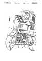
- FIG. 1is a perspective view of the front and right sides of a processing system that embodies the features of the invention, with some access panels and doors open to expose the interior portions to view;
- FIG. 2is a perspective view of the front and left sides of the system shown in FIG. 1, with other access panels and doors open to expose the interior portions to view;
- FIG. 3is a top view of the interior of the system shown in FIG. 1, with some portions shown diagrammatically;
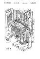
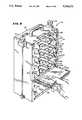
- FIG. 4is a perspective view of the interior regions of the system, showing the tray holding stations, the detecting station, and associated carrier mechanism, with portions broken away;
- FIG. 5is an enlarged perspective view of the right side of the interior regions of the system shown in FIG. 4;
- FIG. 6is an enlarged perspective view of the carrier mechanism associated with the system, taken from left side, showing the movable platform that holds the specimen tray in its outward extended position;
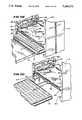
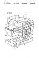
- FIGS. 7A and 7Bare side sectional views, taken generally along line 7--7 in FIG. 3, showing the movable platform picking up a specimen tray from a holding station;
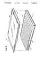
- FIG. 8is a perspective view of the tray and associated cover that hold specimens during processing within the system
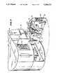
- FIG. 9is a perspective view of an operator loading a specimen tray (with cover) into the outward facing side of a holding station slot;
- FIG. 10is a perspective view of a specimen tray (with cover) stored within a holding station slot, as viewed from the outward facing side of the holding station;
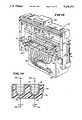
- FIGS. 11A, 11B, and 11Care perspective views of the movable platform operating within a holding station to remove a specimen tray, leaving the cover behind, as viewed from the inward facing side of the holding station;
- FIG. 12is a perspective view of the movable platform operating within a holding station to insert a specimen tray, leaving the cover behind, as viewed from the inward facing side of the holding station;
- FIG. 13is an enlarged perspective view of the photometric detecting station associated with the system shown in FIG. 1;
- FIG. 14is an enlarged side section view, taken generally along line 14--14 in FIG. 13, of the interior of two adjacent tray wells held upon the platform while in the photometric detecting station;
- FIG. 15is an enlarged perspective view, with portions broken away, of the light source associated with the photometric detecting station shown in FIG. 13;
- FIG. 15Ais a schematic showing the sequence of obtaining a processing reading at the photometric detecting station
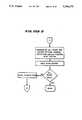
- FIG. 15Bis a schematic flow chart showing the sequence of calibrating the position of the platform relative to the optical channels at the photometric detecting station
- FIG. 16is an enlarged perspective view of the fluorometric detecting station associated with the system shown in FIG. 1, with interior portions shown diagrammatically;
- FIG. 17is an enlarged perspective view, partially exploded, showing the rear portion of the reagent dispensing station carried within an access panel of the system shown in FIG. 1;
- FIG. 18is an enlarged exploded view of the reagent dispensing nozzle, its holder, and the associated docking fixture that embody the features of the invention
- FIG. 19is an enlarged side section view of the reagent dispensing nozzle, its holder, and the associated docking fixture shown in FIG. 18, with the docking fixture being moved into engagement with the nozzle;
- FIG. 20is an enlarged side section view of the reagent dispensing nozzle, its holder, and the associated docking fixture shown in FIG. 18, with the docking fixture engaged with the nozzle;
- FIG. 21is an enlarged side section view of the reagent dispensing nozzle, its holder, and the associated docking fixture shown in FIG. 18, with the docking fixture engaged with the nozzle and transporting the nozzle to the fluid dispensing area of the system shown in FIG. 1;
- FIG. 22is a perspective view showing the manipulation of the reagent dispensing while releasably attached to the docking fixture at the fluid dispensing area of the system;
- FIG. 23is a schematic view of a stepper motor control circuit associated with the system shown in FIG. 1.
- FIGS. 1 to 3show the general arrangement of an analytical system 10 that incorporates the features of the invention.
- the analytical system 10can be used in different environments to carry out different types of analytical, laboratory, and clinical procedures.
- the inventioncan be used in association with systems that require accurate and reproducible transfers of fluid in clinical, medical, and industrial environments.
- the inventionalso can be used in association with systems that do assays for targeted materials or that analyze and identify biologic specimens.
- This Specificationdescribes a preferred embodiment of the invention operating as part of a device for screening liquid samples to identify microorganisms and test for their susceptibility to certain antibiotics.
- the system 10handles trays 12 carrying previously prepared suspensions of microbiologic specimens.
- the system 10incubates the specimens within the trays 12, adds reagents to them, and analyzes them according to a prescribed protocol
- the system 10carries out these processes by sequentially transporting the specimen trays to various work stations 14, 16, 18 under the control of an onboard central microprocessor 20 (see FIG. 3).
- the central processor 20is preprogrammed to follow at least one prescribed analytical protocol.
- the system 10includes stations 14 that hold the specimen trays 12 for incubation; a station 16 that dispenses reagents into the specimen trays; and a station 18 that detects and quantifies the growth of microorganisms in the specimen trays As will be described in greater detail later, the detection station 18 measures microbic growth by either photometric or fluorometric techniques.
- a cabinet 22encloses the stations 14, 16, and 18 and the central processor 20.
- a carrier 24transports the trays 12 among the stations 14, 16, and 18 within the cabinet 22 under the control of the central processor 20.
- the operatorsends and receives system status and control information from the central processor 20 through an onboard input/output panel 26.
- a nearby input/output display cathode ray tube CRT and keyboard console 28is also linked by cable to the central processor 20 (as FIG. 1 shows).
- the system 10also includes an onboard environment controller 30 operated by the central processor 20.
- the controller 30maintains a circulating air flow pattern 32 (shown by arrows in FIG. 3) through ducting within the main incubation region 34 of cabinet 22, where the holding stations 14 are located.
- the air flow pattern 32is heated and humidified to establish conditions necessary to incubate the specimens carried in the holding stations 14.
- the air flow pattern 32typically maintains a temperature of about 37 degrees C within the main incubation region 34.
- the cabinet 22includes doors 36 and 38 that permit periodic access into the enclosed interior regions of the cabinet 22.
- the door 36opens into the main incubation region 34 (see FIG. 2). When open, the door 36 allows the operator to load or remove specimen trays from a holding station 14. To preserve the incubating conditions within the region 34, the central processor 20 normally locks the door 36 to prevent unrestricted access. The central processor 20 opens the door 36 only in response to a proper access request code, which the operator enters using the console 28.
- the door 38opens into the lower region 40 of the cabinet 22, where the reagent dispensing station 16. When open, the door 38 allows the operator access to the interior of the reagent dispensing station 16 to load or remove reagent source containers 42. Since the interior of the reagent dispensing station 16 is largely isolated from the main incubation region 34, the operator can open the door 38 without first entering an access request code to the central processor 20.
- the service panel 44opens into the main incubation region 34.
- the service panel 46opens into the lower region 40 and carriers the entire reagent dispensing station 16.
- the holding stations 14are vertically stacked into towers within the main incubation region 34.
- the number of holding stations 14can vary, as can the number of trays 12 each holding station 14 carries. In the illustrated embodiment, there are eight holding stations 14, each containing six slots 50 to hold individual specimen trays 12 (see FIG. 9 also).
- a carousel 52moves the stacked holding stations 14 in a circular track around the carrier 24.
- a first stepper motor 54powers an associated belt drive 56 under the control of the central processor 20 to index the carousel 52. In this way, each holding station 14 can be brought to an access position, which holding station 14' occupies in FIG. 3. In this position, one side 58 of the holding station 14' faces inward toward the carrier 24, while the other side 60 faces outward toward the access door 36.
- a pair of tie-down bolts 62attach each holding station 14 to the carousel 52. By unfastening the tie-down bolts 62, the operator can remove individual holding stations 14 for maintenance, cleaning, or sterilization.
- Each tray 12 stacked within the holding station 14includes an array of specimen wells or cuvettes 48 (as FIG. 8 best shows) arranged in aligned rows and columns.
- each tray 14includes ninety-six wells 48 arranged in eight rows of twelve wells 48 each.
- the trays 12are intended to be a single-use, disposable component of the system 10. So, the trays 12 are typically made of an inert plastic material.
- the plastic materialcan be light transmissive to permit analysis of the specimens by photometry. Alternatively, the plastic material can be opaque to permit analysis of the specimens by fluorometry.
- the tray wells 48contain various reaction agents. When incubated, the specimens react with these agents within the wells 48 to create differing distinctive patterns of color or turbidity changes, or fluorescence in the tray 12. Sometimes, a reagent must be added to trigger the needed reaction for analysis. By creating and then analyzing these patterns, the system 10 detects the presence of a given type of microorganism and its degree of susceptibility to various microbiotic agents.
- the operatorprepares a culture medium containing a suspension of the microorganism to be analyzed.
- the operatorintroduces this suspension into the wells 48 of a specimen tray 12.
- the operatordoes this task at a specimen preparation station (not shown) outside the system cabinet 22.
- the operatorplaces a cover 86 on the tray 12 to minimize fluid loss by evaporation (see FIG. 8).
- the coverincludes a pair of projecting tabs 88 that extend horizontally beyond two sides of underlying tray 12.
- the processor 20maintains an inventory of trays 12 within the holding stations 14 (as will be described later), and, with it, the processor 20 locates the position of empty holding slots 50.
- the central processor 20provides the operator with a listing of empty holding slots 50. The operator uses this listing to designate a holding station 14 via the data input panel 26 or console 28.
- the central processor 20indexes the carousel 52 to place the user-designated holding station 14 in the access position (where FIGS. 3 and 7A/B show holding station 14, to be).
- the processor 20then unlocks the door 36.
- the operatormanually loads the medium-filled specimen tray 12 with its cover 86 into an open holding slot 50 through the outward facing side 60 of the station 14 (as FIG. 9 best shows).
- each slot 50is open except for opposite pairs of vertically spaced top and bottom support ledges 210 and 212.
- the bottom ledges 212extend farther into the slot 50 than the top ledges 210.
- the bottom ledges 212end with upturned edges or abutment members 214 at both inward and outward facing sides 58 and 60 of the slot 50.
- FIG. 9shows, the operator inserts the tray 12 and cover 86 through a slotted opening 216 in the outward facing side 60 into the slot 50.
- FIG. 10shows, the bottom of the tray 12 comes to rest upon the bottom ledges 212 The upturned edges 214 prevent horizontal movement of the tray 12 within the slot 50.
- the projecting tabs 88 on the overlying cover 86extend above the plane of the top support ledges 210, making no contact with them.
- Springs 218press against the projecting tabs 88 to hold the cover 86 on the underlying tray 12.
- the central processor 20After loading the tray 12, the operator closes the door 36. From this point onward, the central processor 20 automatically conducts the analysis of the tray 12 without further involving the operator.
- the central processor 20sequentially actuates the carrier 24 to shuttle each tray 12 to and from the holding station 14, stopping either at the detection station 18 or the reagent dispensing station 16.
- the carrier 24transports a given tray 12 several times between the holding station 14 and detection station 18 for successive analysis, with at least one intermediate stop at the reagent dispensing station 16.
- the detection station 18quantifies the microbic growth observed on each specimen tray 12.
- the central processor 20is linked to an external printer station (not shown). There, the processor 20 periodically generates written reports for the operator that contain a complete analysis for each specimen tray 12.
- FIGS. 5 and 6show the details of the carrier 24.
- the carrier 24includes a frame 64 supported on a pair of vertical shafts 66.
- a second stepper motor 68powers an associated belt drive 70 to rotate a vertical axis lead screw 72 under the control of the central processor 20.
- the rotating vertical lead screw 72moves the carrier frame 64 in a stepwise fashion up and down along the shafts 66. This mode of operation brings the carrier frame 64 into vertical alignment with any selected slot 50 of a holding station 14 occupying the access position.
- the carrier 24also includes a horizontal platform 74 mounted on a pair of tracks 76 on the frame 64.
- a third stepper motor 78powers an associated belt drive 80 (see FIG. 6) to rotate a horizontal axis lead screw 82 under the control of the central processor 20.
- Rotation of the lead screw 82advances the platform 74 in stepwise fashion along a horizontal path between a fully retracted position within the carrier frame 64 (see FIGS. 5 and 7B) and a fully extended position outside the carrier frame 64 (see FIGS. 6 and 7A).
- FIG. 7Ashows, when moved toward its fully extended position, the horizontal platform 74 enters an aligned holding slot 50 beneath the occupying tray 12 through the inward facing side 58 of the station 14. Slight rotation of the vertical lead screw 72 lifts the platform 74. The open bottom of each slot 50 permits upward movement of the platform 74 into engagement with the underside of the tray 12.
- the platform 74includes an array of pockets 84.
- the convex undersides of the tray wells 48nest within the pockets 84 so that the tray 12 cannot slide horizontally on the platform 74.
- the pocket bottomsdefine an opening 85 and do not interfere with the intended transmission of light through the tray wells 48.
- FIGS. 11Ashows, further operation of the lead screw 72 lifts the platform 74 and, with it, the covered tray 12 within the slot 50.
- the lifting movement(coupled with slight movement of the platform 74 inward, as shown by arrows in FIG. 11A) slips the inward facing edges of the projecting cover tabs 88 into upper detents 220, which are located within the slot 50 above the top support ledges 210.
- FIG. 11Bshows, slight opposite rotation of the lead screw 72 lowers the tray 12, leaving the edges of the cover 86 engaged within the upper detents 220.
- FIG. 11Cshows, rotation of the horizontal lead screw 82 moves the platform 74 out of the holding slot 50.
- the platform 74carries the engaged tray 12, but leaves the cover 86 behind (as FIG. 7B also shows).
- the portion 222 of the top support ledge 210 that extends toward the outward facing side 60 of the slot 50slopes downward toward the bottom support ledge 212.
- the springs 218press against the cover 86 at the junction of the sloped portion 222 with the rest of the top support ledge 210.
- FIG. 11Cshows, as the platform 74 withdraws the tray 12, the springs 218 pivot one end of the cover 86 down against the sloped portion 222, while the opposite end of the cover 86 remains engaged within the upper detents 220.
- the cover 86assumes this tilted position within the slot 50 (as FIG. 7B also shows) as the platform 74 withdraws the tray 12.
- the cover 86remains in this tilted position as the platform 74 transports the associated coverless tray 12 outside the holding slot 50.
- FIG. 12shows, when the platform 74 returns the tray 12 to the slot 50, the entering edge of the tray 12 contacts the tilted portion the cover 86.
- the horizontal movement of the tray 12pulls the cover 86 free of the detents 220, as FIG. 12 shows.
- the horizontal movementalso pivots the cover 86 about the spring back into its original horizontal position on top of the tray 12. Slight rotation of the vertical lead screw 72 lowers the platform 64 from engagement with the now covered tray 12. Rotation of the horizontal lead screw 82 returns the platform 74 to its retracted position within the frame 64.
- the central processor 20maintains an inventory of the trays 12 undergoing processing within the system 10. As FIG. 8 shows, each tray 12 carries a unique identification label 206 written in bar code or another machine readable format.
- the carrier 24includes a scanning device 208 (see FIG. 4) for reading the tray labels 206.
- the central processor 20indexes the carousel 52 to bring the holding station 14 to a scanning position in alignment with the scanning device 208 (which is essentially 180 degrees from the access position previously described).
- the central processor 20operates the vertical lead screw 72 to advance the scanning device 208 to view the label 206 of each tray 12 in the holding station 14, while operating the carousel 52 to advance the label 206 horizontally past the scanning device 208 to scan in the bar code information it contains.
- the central processor 20creates and updates an inventory record of trays 12 each time an operator loads a tray 12 into the system 10.
- the central processor 20further updates the inventory record for each tray 12 to note the time and nature of the processing steps conducted.
- the inventory recordestablishes the holding station slot for the tray 12, the time the tray entered the system, the time and nature of each processing step involving the tray 12, and the results of the analyzes conducted on the tray 12.
- the central processor 20relies upon the preprogrammed protocol and real time inventory record it creates to control the processing sequence for each tray 12 within the system 10.
- the central processor 20coordinates the rotation of the vertical lead screw 72 with the carousel belt drive 56 to orient the carrier 24 with a selected slot 50 of a holding station 14. Then, by operating the horizontal lead screw 82, the central processor 20 operates the platform 74 to remove the specimen tray 12 and later return the specimen tray 12 to the aligned holding slot 50.
- the carrier 24transports the engaged specimen tray 12 outside the holding slot. 50 to either the detection station 18 or the reagent dispensing station 16, depending upon the commands of the central processor 20.
- the carrier frame 64supports the detection station 18. Still, it should be appreciated that the detection station 18 could be located away from the carrier frame 64 at another location within the cabinet 22.
- FIG. 13shows the details of the detection station 18
- the detection station 18includes both a photometric reader 96 and a fluorometric reader 98.
- the photometric reader 96optically detects the presence of either color change or turbidity in a given specimen and by that derives a measure of microbiotic activity.
- the fluorometric reader 98detects fluorescence within a given specimen to measure microbiotic activity. Whether a given specimen undergoes analysis by the photometric reader 96 or the fluorometric reader 98 depends upon the particular protocol of the analytical procedure that the central processor 20 follows.
- the photometric reader 96includes a light source assembly 100 comprising twelve fiber optic emitter lines 102 that lead from a single light source 104 (the details of which are shown in FIG. 15).
- the optic emitter lines 102are arranged in a horizontal, spaced apart relationship on the frame 64 below the path of movement of the platform 74. The distance between adjacent optic emitter lines 102 corresponds with the distance between adjacent wells 48 within each row on the specimen tray 12.
- the optic emitter lines 102transmit light upward through the specimen tray 12 on the platform 74, individually illuminating one entire row (i.e., twelve wells 48) at a time.
- Each optic emitter line 102includes a lens (not shown) that condenses the light beam exiting the optic fiber into a narrow vertical beam, by that maximizing the illumination of each well 48.
- the light source 104is separated from the input end of each fiber optic line 102 by a color wheel 108.
- the wheel 108includes six light filters 110 and one opaque disk 111 spaced about its periphery. Each filter 110 limits the light entering the fiber optic lines 102 to a discrete, predetermined wavelength.
- the opaque disk 111blocks all transmission of light to the emitter line 102 when, for example, when the fluorometric reader 98 is in operation or during calibration, as set forth in more detail later.
- a fourth stepper motor 112rotates the color wheel 108 to position the desired filter 110 or disk 111 in the light path under the control of the central processor 20.
- the photometric reader 96also includes twelve photodiode detectors 106 paired with the twelve optic emitter lines 102.
- the twelve photodiode detectors 106face the optic emitter lines 102 on the frame 64 above the path of movement of the platform 74.
- the photodiode detectors 106sense light after its transmission through the specimens in the wells 48.
- the central processor 20indexes the tray-carrying platform 74 stepwise between the twelve paired emitters and detectors 102/106.
- the photometric reader 96includes a programmable gain amplifier 113 (see FIG. 15A) that is capable of providing fixed levels of amplification, called gain stages.
- a digital processor 114analyzes the sensed signal at a preselected selected gain stage to determine either the color or turbidity of the specimens.
- multiple photometric readingsare typically taken of the specimens at predetermined intervals during the incubation period.
- Each emitter/detector pair 102/106constitutes one independent optical channel C1 to C12 that, in use, transits one tray well 48.
- the central processor 20independently calibrates each optical channel C1 to C12 to obtain a reading representative of the absorption of the sample within the associated tray well 48.
- Independent calibrationallows the differences between the twelve individual channels C1 to C12 to be cancelled out.
- Independent calibrationaccommodates greater mechanical and electrical tolerances among the channels C1 to C12 than the calibration of all channels to a common reference point. Independent calibration cancels out these differences among the channels without adversely affecting the overall accuracy of the photometric reader 96.
- the calibration procedure for each optical channel C1 to C12is the same.
- the procedurebegins with the platform 74 carrying no tray 12.
- the central processor 20places the opaque disk 111 in the light path to block transmission of light to all optical channels.
- a separate readingis taken for each channel at each gain stage of the amplifier 113. These readings represents the dark signals (electrical offset) for each gain stage of each channel.
- the central processor 20retains these readings for each optical channel in memory.
- the central processor 20then sequentially brings a filter 110 into the light path. While no tray 12 occupies the platform 74, a reading is taken.
- the central processor 20selects the gain stage of the amplifier 113 that achieves an on-scale reading. This becomes the preselected gain stage for that channel for that particular filter 110 (wavelength).
- the on-scale reading at that gain stagebecomes the reference for that channel for that particular filter 110 (wavelength). Because each channel is calibrated independent of the other channels, each optical channel may and probably will have a different gain stage and reference for each filter 110.
- the calibration procedurerepeats this sequence for each filter (wavelength) 110, obtaining an associated gain stage and reference for each channel.
- the central processorretains these values in memory.
- the central processor 20thus maintains for each filter (wavelength) 110 three calibration values for each optical channel C1 to C12. These calibration values represent the gain stage (G) selected to obtain an on-scale reading for the filter 110; the reference reading taken at the selected gain stage (R G ); and the dark reading earlier obtained for the selected gain stage (D G ).
- FIG. 15Ashows with respect to each optical channel (designated C n in FIG. 15A), a subsequent reading in that optical channel at a particular filter wavelength (R RAW ) is taken at the selected gain stage (G) for that filter 110.
- the central processoralters the subsequent reading (R RAW ) to obtain a processing reading (R PROC ) for each optical channel, as follows: ##EQU1##
- the processing reading R PROCis representative of the absorbance of the sample taken at that optical channel. Due to the calibration process, the processing reading R PROC for each optical channel is hardware independent.
- the central processor 20also calibrates the position of the platform 74 relative to the optical channels to properly locate the openings 85 in the platform 74 within the light paths.
- FIG. 15Bshows the sequence of the platform calibration procedure.
- the platform 74is drawn through the light paths. For each optical channel, the amount of light reaching the associated detector 106 increases as the outer edge of the associated opening 85 enters the light path. The light signal reaches a maximum value when the center of the opening 85 occupies the light path. The light signal then decreases as the inner edge of the opening 85 enters the light path to block the light.
- the central processor 20marks the position of the platform 74 (based upon the particular step of the stepper motor 78) when a preselected threshold value is reached at the inner and outer edges of the associated opening 85.
- the center of the opening 85is determined for that particular optical channel by averaging these two marked positions.
- the determined centers for the optical channelare themselves averaged to derive an average center position for the stepper motor 78 for each row of openings 85.
- the central processor 20indexes the platform 74 to best position the centers of the openings 85 along each row into the optical channels
- the openings 85are fixed on the platform 74, and the tray is preformed so that the centers of its wells 48 nest within the platform 74 in registration with the centers of the openings 85.
- the calibration procedure just described and as set forth in FIG. 15Bneed be performed for each system 10 only upon initial setup and after repair and/or replacement of the platform 74 or its associated drive assemblies.
- FIG. 16shows the details of the fluorometric reader 98.
- the fluorometric reader 98includes a movable head 116 that travels along a horizontal track 118 on the carrier frame 64 above the path movement of the platform 74.
- the track 118extends transversely across the path of platform movement
- a fifth stepper motor 120powers an associated belt drive 122 that moves the head 116 back and forth along the track 118.
- the head 116encloses a fluorometer, the interior details of which are shown in FIG. 16.
- the fluorometerincludes a source lamp 124 that directs light to an excitation filter 126 through a quartz light path 128.
- An output lens 130directs the out coming light onto the specimen contained in an underlying well 48.
- the specimencontains a material that, in the presence of a target microorganism, reacts to the light energy by fluorescing.
- the resulting fluorescenceis directed by an input lens 132 to an emission filter 134 for the expected wavelength.
- a photomultiplier tube 136 and a preamplifier 138translate the light signal to an analog output that is directly proportional to the amount of fluorescence detected.
- An analog-to-digital converter 140(which is carried on the frame 64 and is attached to the movable head 116 by a cable 142) converts the analog output of the photomultiplier tube 136 to digital output.
- the converter 140also includes the power supply for components carried within the movable head 116.
- the carrier platform 74indexes a row of wells 48 into position below the head 116.
- the central processor 20moves the head 116 down the wells 48, obtaining the fluoresced light signal for each well 48 and transmitting it to the processor 140.
- FIGS. 17 to 22show the details of the reagent dispensing station 16.
- the reagent dispensing station 16occupies the region 40 below the carousel 52 at the front of the cabinet 22 (see FIGS. 1 and 2). It is housed within the service panel 46 essentially out of the main incubation region 34 area of the system 10.
- the panel 46contains a reagent dispensing area 144, a pressurized reagent source 146, and a reagent dispensing nozzle 148.
- the source 146contains different reagent types contained in individual containers or vials 42 (see FIGS. 1 and 15).
- Tubing manifold 150connects each vial 42 to a positive pressure pump 152.
- Each reagent vial 42also includes an outlet tube 154 with an inline solenoid valve 156 that is under the control of the central processor 20. When closed, the solenoid valve 156 blocks the flow of reagent from the pressurized vial 42. When opened, the solenoid valve 156 permits reagent to flow under positive pressure from the vial 42 through the associated outlet tubing 154.
- the outlet tubing 154 for the reagent vials 42all leads to the dispensing nozzle 148.
- the dispensing nozzle 148includes individual fluid dispensing ports 158 (see FIG. 18), one for each type of reagent.
- the solenoid valve 156opens for a particular source reagent vial 42
- the particular reagent in the vial 42flows under positive pressure out the associated dispensing port 158 in the nozzle 148.
- the dispensing ports 158are symmetrically arranged at predetermined intervals relative to the centerline of the nozzle 148 to allow precise positioning over the intended well 48 by the stepper motors controlled by the central processor 20 (as will be described in greater detail later).
- a holder 160When not in use, a holder 160 retains the nozzle 148 on the dispensing station 16 away from the fluid dispensing area 144. In the illustrated embodiment, the holder 160 is located a short distance below the dispensing area 144 and close to the reagent source 146.
- a movable latch 162(see FIG. 18) within the holder 160 is biased by springs 164 into engagement with a tab 166 on the nozzle 148. This engagement locks the nozzle 148 in place inside the holder 160 (as FIG. 19 shows).
- Tubing 176periodically brings washing fluid from a source container 182 into the holder 160 using the positive pressure pump 184.
- the periodic pressurized spray of fluidwashes the interior of the holder 160. It can also be used to wash the nozzle 148 resting within the holder 160.
- the washing fluiddrains through an exit tube 178 into a disposable collection bag 180.
- Tubing 177periodically brings pressurized air into the holder 160 to air dry the nozzle 148 after washing.
- the compact arrangement of all components of the reagent dispensing station 16 out of the main incubation region 34allows the reagent source 146 to be positioned close to the dispensing nozzle 148.
- the lengths of outlet tubing 154 supplying reagent to the nozzle 148can be significantly shortened.
- the tubing 154need be long enough only to allow the nozzle 148 to reach the holder 160 and the reagent dispensing area 144.
- the tubing 154need not be long enough to allow the nozzle to reach beyond the reagent dispensing station 16 and into the main incubation region 34 of the system 10. Because of the short length of the tubing 154, the amount of positive pressure required to convey the reagent in the system 10 can be considerably reduced.
- the reagent dispensing stationuses only about 25% as much tubing. It also operates at a fluid pressure of only 3 PSI (pounds per square inch) instead of the 8 PSI that conventional systems must use. The reduction of positive pressure within the system considerably reduces the formation of air blocks caused by fluid outgassing within the tubing 154.
- a solenoid 168selectively energized by the central processor 20 moves the latch 162 away from the nozzle tab 166 against the force of the biasing spring 164 (as FIG. 20 shows). This frees the nozzle 148 for removal from the holder 160 when it is time to dispense reagent.
- the carrier 24includes a docking fixture 170 for engaging the nozzle 148 to transport it between the holder 160 and the reagent dispensing area 144. While at the dispensing area 144, the central processor 20 coordinates the movement of the platform and the docking fixture 170 with operation of the reagent dispensing source 146 to introduce reagent into one or more specimen-containing wells.
- the docking fixture 170releases the nozzle 148 after dispensement of reagent. More particularly, the carrier 24 returns the nozzle 148 to the holder 160 and there releases the docking fixture 170. This mode of operation frees the carrier 24 for other transport functions within the system 10, while the nozzle 148 lays at rest within its holder 160.
- the docking fixture 170is attached to the movable head 116 of the fluorescence reader 98. Operation of the fifth stepper motor 120 moves the docking fixture 170 along the horizontal track 118 above the tray platform 74.
- the illustrated embodimentemploys magnetism to releasably engage the docking fixture 170 to the nozzle 148.
- the docking fixture 170carries a permanent rare earth magnet 174.
- the nozzle 148includes a surface 172 that nests within the fixture 170.
- the mating surface 172includes material that is attracted by the magnet 174 the fixture 170 carries.
- the mating surface 172could carry another rare earth magnet.
- the central processor 20coordinates the operation of the first, second, and third stepper motors 54, 68, and 78 to engage a selected specimen tray 12 on the platform 74 within the main incubation region 34 of the system 10.
- the central processor 20moves the platform 74 into its fully retracted position within the carrier frame 64.
- the central processor 20then moves the carrier 24 vertically downward into the reagent dispensing region 40 (as FIG. 19 shows).
- the nozzle 148rests in a locked condition within the holder 160 (i.e., the latch solenoid 168 is not energized).
- the docking fixture 170moves downward and nests with the nozzle surface 172 (as FIG. 20 shows).
- the nesting fixture 170magnetically engages the nozzle surface 172.
- the central processor 20energizes the solenoid 168 to withdraw the latch 162, freeing the nozzle 148 within the holder 160.
- the central processor 20moves the carrier 24 vertically upward.
- the fixture 170lifts the magnetically engaged nozzle 148 from the holder 160 and into the reagent dispensing area 144 (as FIGS. 21 shows).
- the central processor 20then operates the third stepper motor 78 to move the tray-carrying platform 74 out of the carrier frame 64 into the fluid dispensing area 144.
- the central processor 20horizontally positions a row of the specimen tray 12 beneath the nozzle 148 while it transversely positions the nozzle 148 along this row to bring the desired specimen well 48 under the desired reagent dispensing port 158.
- the central processor 20then opens the solenoid valve 156 associated with the vial 42 for the desired reagent to dispense a predetermined aliquot of the desired reagent into the selected well 48.
- the central processor 20positions the nozzle 148 engaged by the movable fixture 170 by dead reckoning.
- the processor 20measures the position of the fixture 170 along the track 118 in steps sent to the fifth stepper motor 120 from the fixture's home position.
- the drive system of the stepper motor 120is calibrated using the fluorometer located within the transport head 116, which also carries the fixture 170.
- the system start-up routineincludes an initialization process that uses an onboard encoder bar 224 and an optical interrupter 226. As FIGS. 5 and 6 best show, the optical interrupter 226 is carried on the movable head 116 of the fluorescence reader 98 behind the belt drive 122.
- the encoder bar 224is also carried on the platform 74 behind the belt drive 122.
- the encoder bar 224includes a series of spaced apart teeth 228 sandwiched between the optical interrupter 226 along its path of movement.
- the centerlines of the teeth 228mark the centerline positions of the tray wells 48 when the tray 12 is present on the platform 64.
- the optical interrupter 226scans the encoder bar 224.
- the teeth 228block light transmission through optical interrupter 226.
- the spacing between the teeth 228allows light transmission through the optical interrupter 224.
- the interrupter 224senses sequential conditions of light and no light.
- the central processor 20uses this table to guide the centerline of the nozzle 148 to a particular well 48 during reagent dispensing operations. Additional incremental stepping actions of the motor 78 and the motor 120 under the control of the central processor 20 align the selected nozzle port 158 over the selected well 48.
- the central processor 20moves the tray-carrying platform 74 into its fully retracted position.
- the central processor 20vertically lowers the carrier 24 to return the nozzle 148 to its holder 160.
- the solenoid 168is not energized, and the spring-biased latch 162 snaps into locking engagement with the nozzle tab 166.
- the central processor 20moves the carrier 24 vertically upward.
- the magnet attraction holding the nozzle surface 172 to the fixture 170is such that vertical movement of the carrier 24 while the nozzle 148 is locked within the holder 160 overcomes the force of the magnetic coupling, separating the nozzle surface 172 from the docking fixture 170.
- the carrier 24is thereby freed to return the engaged specimen tray 12 (now with added reagent) back to the main incubation region 34 for further processing.
- the central processor 20includes a motor driver system 186 (see FIG. 23) for controlling the stepper motors 54; 68; 78; 112; and 120 associated with the system 10.
- the system 186includes a conventional field effect transistor (FET) 188 connected in series with the motor coil 190
- a phase controller 191controls voltage to the FET 188, by that controlling its phase of operation. In an on phase, the controller 191 supplies voltage to the FET 188. This allows current to flow through the coil 190. In an off phase, the controller 191 supplies no voltage to the FET 188. This interrupts current flow through the coil 190.
- FETfield effect transistor
- the associated stepper motorincludes a rotor and two or more coils 190 under the control of the controller 191.
- the controller 191successively supplies current to the coils 190 to step the motor rotor to its successive operating positions.
- a FET controller 193provides either a true or not true enable signal that switches the FET 188 for the coil 190 between an on state (when true) and an off state (when not true).
- the chop controller 201When current is applied to the coil 190 (i.e., during its on phase of operation), the chop controller 201 rapidly switches the FET 188 between its on and off states, modulating the current and keeping it from rising above the nominal motor current (for example, 5 amps). The current rises and falls as the FET 188 switches on and off, creating a conventional unipolar chopping mode drive effect. In the chopping mode, the FET 188 keeps the average current in the coil 190 from rising above the nominal, relatively low motor current, despite a relatively high applied voltage (for example, 40 volts).
- the system 186also includes a flyback circuit 192 for each motor coil 190.
- the flyback circuit 192includes a conventional steering diode 194 and a conventional zener-diode 196.
- the zener-diode 196is connected in the reverse bias direction. The zener-diode 196 thus normally resists flow of current in the direction through the steering diode 194, until its breakdown voltage is reached.
- the flyback circuit 192also includes a conventional snubber circuit, consisting of series resistor 198 and capacitor 200.
- the flyback circuit 192further includes two conventional bipolar transistors 202 and 204.
- the first transistor 202is a PNP-type whose base is connected to the coil controller 191.
- the first transistor 202acts as a switch under the control of the coil controller 1191.
- the first transistor 202conducts current (a switched closed state) when current is supplied to the coil 190 (during its on phase of operation).
- the first transistor 202does not conduct current (a switched opened state) when no current is supplied to the coil 190 (during its off phase of operation).
- the second transistor 204is an NPN-type. Its base to emitter voltage is selectively biased to two different voltages, one high and the other low, depending upon a phase of operation of the coil 190. The bias voltage, in turn, affects the overall dissipation of power through the flyback circuit 192.
- the collector of the second transistor 204is connected to the steering diode 194 to conduct current from the coil 190.
- the emitter of the second transistor 204is connected to the coil 190 to return this current to the coil 204, minus any energy dissipated by the transistor 204.
- the base of the second transistor 204is connected to the collector of the first transistor 202.
- the collector of the second transistor 204is connected to the emitter of the first transistor 202 between the steering diode 194 and the zener-diode 196.
- the zener-diode 196is connected in the reverse biased direction (during the off phase of the controller 191) between the collector and base of the second transistor 204.
- the coil 190will dissipate retained stored energy into the flyback circuit 192 whenever the FET 188 interrupts current flow through the coil 190 (i.e., when the FET 188 is switched off while the controller 191 operates the coil 190 in its on phase mode).
- the coil 190also will dissipate retained stored energy into the flyback circuit 192 whenever current to the coil 190 itself terminates (i.e., when the controller 191 switches operation from the on phase mode to the off phase mode).
- the FET 188repeatedly interrupts current flow through the coil 191 at short intervals while the motor coil 190 operates in its chopping mode. Whenever the FET 188 switches off (when the controller 193 provides a "not true” enable signal) energy discharged by the coil 190 enters the flyback circuit 192.
- the coil 190is in its on phase.
- the coil controller 191biases the base of the first transistor 202 to a switched closed state.
- the first transistor 202conducts current at a first voltage, which is less than the breakdown voltage of the zener-diode 196.
- the current in the flyback circuit 192flows through the steering diode 194 and through the path of least electrical resistance, which is through the first transistor 202.
- the zener-diode 196operates below its breakdown voltage in its reverse direction to block current flow in its path.
- the currentflows through the first transistor 202 to the base of the second transistor 204.
- the first transistor 202biases the base emitter junction of the second transistor 204 at the first, relatively low voltage.
- the first voltageis generally about 2 volts.
- the flyback circuit 192recirculates current through the second transistor 204 with little dissipation during the intervals while the FET 188 is switched off. This sustains a smooth, constant torque while the coil 190 is energized (i.e., receiving voltage) and operating in its chopping mode. Due to the low voltage mode of the flyback circuit 192, the stepper motor provides steady, sustained power.
- the controller 191switches the coil 190 to its off phase.
- the coil 190again discharges its energy into the flyback circuit 192 (the enable signal transmitted to the FET 188 has no effect once the controller 191 operates in its off phase). Since the coil 190 is now in its off phase, the first transistor 202 is in its switched open state and does not conduct current.
- the currentflows through the steering diode 194 directly into the path of the zener-diode 196.
- the reverse currentis such that the zener-diode 196 quickly reaches its breakdown voltage.
- the zener-diode 196then conducts current to bias the second transistor 204 at a second voltage, which is the breakdown voltage of the zener-diode 196.
- the second voltageis generally about 180 volts.
- the flyback powerquickly dissipates the energy stored in the coil 190. This rapid dissipation of energy provides a smooth and quick transition of voltage to the successor coil.
- the high voltage mode of the flyback circuit 192provides sustained speed to the stepper motor.
- system 10in the illustrated embodiments is not intended to limit the scope of the invention to the particular types of analytical systems or particular type of analytical techniques disclosed in this specification.
- system 10 that embodies the inventioncan be used to conduct different analyzes, besides the microbiotic susceptibility procedures described. It will be seen and appreciated that the invention is applicable for use with diverse analytical types and techniques, though they are not all described in detail in this application.
Landscapes
- Chemical & Material Sciences (AREA)
- Health & Medical Sciences (AREA)
- Chemical Kinetics & Catalysis (AREA)
- Analytical Chemistry (AREA)
- General Health & Medical Sciences (AREA)
- Clinical Laboratory Science (AREA)
- Life Sciences & Earth Sciences (AREA)
- Physics & Mathematics (AREA)
- Hematology (AREA)
- Biochemistry (AREA)
- General Physics & Mathematics (AREA)
- Immunology (AREA)
- Pathology (AREA)
- Automatic Analysis And Handling Materials Therefor (AREA)
- Analysing Materials By The Use Of Radiation (AREA)
- Sampling And Sample Adjustment (AREA)
- Devices For Use In Laboratory Experiments (AREA)
- Investigating Or Analysing Materials By Optical Means (AREA)
Abstract
Description
Claims (17)
Priority Applications (8)
| Application Number | Priority Date | Filing Date | Title |
|---|---|---|---|
| US07/786,185US5266272A (en) | 1991-10-31 | 1991-10-31 | Specimen processing and analyzing systems with a station for holding specimen trays during processing |
| ES92923233TES2094377T3 (en) | 1991-10-31 | 1992-10-27 | PROCESSING SYSTEMS AND SAMPLE ANALYSIS WITH STATION TO SUPPORT THE SAMPLE CUVES DURING PROCESSING. |
| JP5508491AJPH06504134A (en) | 1991-10-31 | 1992-10-27 | Specimen processing and analysis system with stations for holding specimen trays during processing |
| EP92923233AEP0565696B1 (en) | 1991-10-31 | 1992-10-27 | Specimen processing and analyzing systems with a station for holding specimen trays during processing |
| CA002099289ACA2099289A1 (en) | 1991-10-31 | 1992-10-27 | Specimen processing and analyzing systems with a station for holding specimen trays during processing |
| DE69213711TDE69213711T2 (en) | 1991-10-31 | 1992-10-27 | System for the treatment and analysis of samples, with a station for holding the sample plates during the treatment |
| PCT/US1992/009083WO1993008914A1 (en) | 1991-10-31 | 1992-10-27 | Specimen processing and analyzing systems with a station for holding specimen trays during processing |
| AU29187/92AAU650180B2 (en) | 1991-10-31 | 1992-10-27 | Specimen tray holder |
Applications Claiming Priority (1)
| Application Number | Priority Date | Filing Date | Title |
|---|---|---|---|
| US07/786,185US5266272A (en) | 1991-10-31 | 1991-10-31 | Specimen processing and analyzing systems with a station for holding specimen trays during processing |
Publications (1)
| Publication Number | Publication Date |
|---|---|
| US5266272Atrue US5266272A (en) | 1993-11-30 |
Family
ID=25137837
Family Applications (1)
| Application Number | Title | Priority Date | Filing Date |
|---|---|---|---|
| US07/786,185Expired - LifetimeUS5266272A (en) | 1991-10-31 | 1991-10-31 | Specimen processing and analyzing systems with a station for holding specimen trays during processing |
Country Status (8)
| Country | Link |
|---|---|
| US (1) | US5266272A (en) |
| EP (1) | EP0565696B1 (en) |
| JP (1) | JPH06504134A (en) |
| AU (1) | AU650180B2 (en) |
| CA (1) | CA2099289A1 (en) |
| DE (1) | DE69213711T2 (en) |
| ES (1) | ES2094377T3 (en) |
| WO (1) | WO1993008914A1 (en) |
Cited By (70)
| Publication number | Priority date | Publication date | Assignee | Title |
|---|---|---|---|---|
| US5508198A (en)* | 1994-07-06 | 1996-04-16 | Ganz; Robert A. | Storage and incubation apparatus for temperature sensitive medical test samples |
| US5519635A (en)* | 1993-09-20 | 1996-05-21 | Hitachi Ltd. | Apparatus for chemical analysis with detachable analytical units |
| US5567387A (en)* | 1994-11-07 | 1996-10-22 | Johnson & Johnson Clinical Diagnostics, Inc. | Cuvette conveyor and sensor |
| US5573950A (en)* | 1994-05-11 | 1996-11-12 | Minnesota Mining And Manufacturing Company | Cassette for disposable microorganism culturing media and automated scanning system |
| US5573727A (en)* | 1992-05-13 | 1996-11-12 | Australian Biomedical Corporation Ltd. | Automatic staining apparatus for slide specimens |
| DE29712535U1 (en)* | 1997-07-16 | 1997-09-18 | Bodenseewerk Perkin-Elmer GmbH, 88662 Überlingen | Sample delivery device |
| US5731157A (en)* | 1993-12-30 | 1998-03-24 | The Procter And Gamble Company | Two-site allergen immunoassay |
| WO1998022219A1 (en)* | 1996-11-18 | 1998-05-28 | Robbins Scientific Corporation | Apparatus for multi-well microscale synthesis |
| US5795784A (en) | 1996-09-19 | 1998-08-18 | Abbott Laboratories | Method of performing a process for determining an item of interest in a sample |
| US5856194A (en) | 1996-09-19 | 1999-01-05 | Abbott Laboratories | Method for determination of item of interest in a sample |
| US5882603A (en)* | 1997-10-15 | 1999-03-16 | Point Plastics Incorporated | Support rack for pipette tips |
| US6050719A (en)* | 1998-01-30 | 2000-04-18 | Affymetrix, Inc. | Rotational mixing method using a cartridge having a narrow interior |
| US6054100A (en)* | 1996-11-18 | 2000-04-25 | Robbins Scientific Corporation | Apparatus for multi-well microscale synthesis |
| US6129428A (en)* | 1996-08-05 | 2000-10-10 | Kendro Laboratory Products Gmbh | Storage device for objects, storage station and air-conditioned cabinet |
| US20010007640A1 (en)* | 1997-07-16 | 2001-07-12 | Edwards Glenn R. | Sample transporter |
| US6267927B1 (en)* | 1997-11-19 | 2001-07-31 | Grupo Grifols, S.A. | Apparatus for performing laboratory tests automatically |
| USD448487S1 (en) | 1997-10-10 | 2001-09-25 | Sakura Finetek U.S.A., Inc. | Specimen cassette |
| US6332636B1 (en)* | 1998-07-14 | 2001-12-25 | Bayer Corporation | Robotics for transporting containers and objects within an automated analytical instrument and service tool for servicing robotics |
| US6386749B1 (en)* | 2000-06-26 | 2002-05-14 | Affymetrix, Inc. | Systems and methods for heating and mixing fluids |
| US6395231B1 (en)* | 1997-10-21 | 2002-05-28 | Cybio Instruments Gmbh | Pipette and handling automatic machine for microtitration plates with permeable bases |
| US20020094581A1 (en)* | 1998-02-24 | 2002-07-18 | Michael Cole | Method and apparatus for determining temperature of and controlling the evaporation of liquid samples |
| US20030017085A1 (en)* | 1998-08-10 | 2003-01-23 | Caliper Technologies Corp. | High throughput microfluidic systems and methods |
| US20030032191A1 (en)* | 2001-07-30 | 2003-02-13 | Hilson Richard O. | Sample processing apparatus and methods |
| US6568770B2 (en) | 2000-05-19 | 2003-05-27 | Kendro Laboratory Products Gmbh | Climatic cabinet |
| US20030215361A1 (en)* | 2002-05-17 | 2003-11-20 | Jang Gi Young | Liquid dispensing and handling system |
| EP1209222A3 (en)* | 2000-11-24 | 2004-01-07 | KENDRO Laboratory Products GmbH | Storage station and incubator |
| US6732662B2 (en)* | 2001-08-10 | 2004-05-11 | Metro Industries, Inc. | Removable tray and tray racking system |
| RU2233002C2 (en)* | 1999-03-01 | 2004-07-20 | Тайко Электроникс Рейкем Нв | Optical fiber spacer control |
| US20040196733A1 (en)* | 2003-04-04 | 2004-10-07 | Canon Kabushiki Kaisha | Target object modification apparatus and control method |
| US20040213651A1 (en)* | 2003-01-10 | 2004-10-28 | Liconic Ag | Automatic storage device and climate controlled cabinet with such a device |
| US20050069401A1 (en)* | 2002-12-18 | 2005-03-31 | Liconic Ag | Climate controlled cabinet with movable carrier |
| US20060018996A1 (en)* | 2004-07-09 | 2006-01-26 | Pollock Paul W | Automatic discovery of a storage configuration method and apparatus |
| US20070010019A1 (en)* | 2001-04-24 | 2007-01-11 | Luoma Robert P Ii | Assay testing diagnostic analyzer |
| US20070190641A1 (en)* | 1992-05-01 | 2007-08-16 | Wilding Peter G | Mesoscale polynucleotide amplification device and method |
| US7303725B2 (en) | 2002-04-15 | 2007-12-04 | Ventana Medical Systems, Inc. | Automated high volume slide staining system |
| US20080112258A1 (en)* | 2003-10-30 | 2008-05-15 | Deka Products Limited Partnership | Two-Stage Mixing System, Apparatus, and Method |
| US20080160599A1 (en)* | 2004-09-03 | 2008-07-03 | Klaus Weber-Matthiesen | Unit For Processing Microbiological Samples |
| US20080190735A1 (en)* | 2001-04-24 | 2008-08-14 | Abbott Laboratories | Assay testing diagnostic analyzer |
| US20080231152A1 (en)* | 2007-03-20 | 2008-09-25 | Liconic Ag | Automated substance storage |
| US7468161B2 (en) | 2002-04-15 | 2008-12-23 | Ventana Medical Systems, Inc. | Automated high volume slide processing system |
| US20090129045A1 (en)* | 2003-05-30 | 2009-05-21 | Adc Telecommunications, Inc. | Fiber containment system |
| US20110020876A1 (en)* | 1992-05-01 | 2011-01-27 | Peter Wilding | Mesoscale polynucleotide amplification devices |
| US20110079071A1 (en)* | 2009-10-07 | 2011-04-07 | Atlas Materials Testing Technology, Llc | Accelerated Weathering Test Apparatus with Calibration-Access Assembly |
| US20150093834A1 (en)* | 2012-12-13 | 2015-04-02 | Roche Molecular Systems, Inc. | Supply module for an automated analyzer |
| US9057714B2 (en) | 2005-05-04 | 2015-06-16 | Abbott Laboratories | Reagent and sample handling device for automatic testing system |
| US9114474B2 (en) | 2011-04-11 | 2015-08-25 | Lincoln Global, Inc. | Accessible work cell |
| JP2016048171A (en)* | 2014-08-27 | 2016-04-07 | シスメックス株式会社 | Sample analyzer |
| WO2016191646A3 (en)* | 2015-05-28 | 2017-01-26 | Bd Kiestra B.V. | Automated method and system for obtaining and preparing microorganism sample for both identification and antibiotic susceptibility tests |
| US20170192022A1 (en)* | 2007-08-06 | 2017-07-06 | Theranos, Inc. | Systems and methods of fluidic sample processing |
| US9784495B2 (en) | 2010-11-24 | 2017-10-10 | Liconic Ag | Storage cassette for laboratory objects |
| WO2017214087A1 (en)* | 2016-06-06 | 2017-12-14 | SciTech Consultants, LLC | Benchtop incubator |
| US10025055B2 (en) | 2014-09-16 | 2018-07-17 | CommScope Connectivity Belgium BVBA | Multi-positionable telecommunications tray |
| US10175440B2 (en) | 2013-03-19 | 2019-01-08 | Adc Czech Republic, S.R.O. | Moveable bend control and patch cord support for telecommunications panel |
| US10184862B2 (en) | 2008-11-12 | 2019-01-22 | Ventana Medical Systems, Inc. | Methods and apparatuses for heating slides carrying specimens |
| US10209470B2 (en) | 2014-09-16 | 2019-02-19 | CommScope Connectivity Belgium BVBA | Telecommunications tray with a cable routing path extending through a pivot hinge |
| US10254496B2 (en) | 2015-04-23 | 2019-04-09 | CommScope Connectivity Belgium BVBA | Telecommunications panel assembly with movable adapters |
| US10294450B2 (en) | 2015-10-09 | 2019-05-21 | Deka Products Limited Partnership | Fluid pumping and bioreactor system |
| CN110023766A (en)* | 2017-03-15 | 2019-07-16 | 株式会社岛津制作所 | Plate device is changed for autosampler |
| US10502917B2 (en) | 2014-09-16 | 2019-12-10 | CommScope Connectivity Belgium BVBA | Telecommunications tray assembly |
| US10694922B1 (en)* | 2018-04-25 | 2020-06-30 | 4 R Oceans, LLC | Drinking straw cleaning caddy |
| US10794805B2 (en) | 2013-12-13 | 2020-10-06 | Ventana Medical Systems, Inc. | Automated histological processing of biological specimens and associated technology |
| US10932647B1 (en) | 2018-04-25 | 2021-03-02 | 4 R Oceans, LLC | Drinking straw cleaning caddy |
| CN112703404A (en)* | 2018-09-13 | 2021-04-23 | 株式会社岛津制作所 | Plate replacing device for automatic sample feeder |
| US11175469B2 (en) | 2017-10-26 | 2021-11-16 | CommScope Connectivity Belgium BVBA | Telecommunications system |
| US11249095B2 (en) | 2002-04-15 | 2022-02-15 | Ventana Medical Systems, Inc. | Automated high volume slide processing system |
| US11293004B2 (en) | 2018-01-09 | 2022-04-05 | SciTech Consultants, LLC | Benchtop incubator including multiple temperature monitors |
| US11299705B2 (en) | 2016-11-07 | 2022-04-12 | Deka Products Limited Partnership | System and method for creating tissue |
| US11319944B2 (en) | 2003-10-30 | 2022-05-03 | Deka Products Limited Partnership | Disposable interconnected pump cassettes having first and second pump chambers with valved inlet and outlet connections |
| US11899010B2 (en) | 2007-10-02 | 2024-02-13 | Labrador Diagnostics Llc | Modular point-of-care devices, systems, and uses thereof |
| US20240085442A1 (en)* | 2022-04-05 | 2024-03-14 | Ventana Medical Systems, Inc. | Pathology slide automation system and method |
Families Citing this family (14)
| Publication number | Priority date | Publication date | Assignee | Title |
|---|---|---|---|---|
| US6309362B1 (en)* | 1992-07-28 | 2001-10-30 | Lamina, Inc. | Method and apparatus for automatically separating particulate matter from a fluid |
| AT403550B (en)* | 1992-08-18 | 1998-03-25 | Robocon Lab Ind Roboter | INCUBATOR |
| EP0721898A1 (en)* | 1995-01-11 | 1996-07-17 | Erwin S. Neumeyer | Storage system and container therefor |
| ES2133129B1 (en)* | 1997-11-19 | 2000-05-01 | Grifols Grupo Sa | APPARATUS FOR THE AUTOMATIC PERFORMANCE OF LABORATORY TESTS. |
| DE20006548U1 (en)* | 2000-04-08 | 2001-08-23 | MWG-BIOTECH AG, 85560 Ebersberg | Device for carrying out chemical or biological processes |
| DE20006549U1 (en)* | 2000-04-08 | 2001-08-16 | MWG-BIOTECH AG, 85560 Ebersberg | Device for carrying out chemical or biological processes |
| DE20114052U1 (en) | 2001-08-23 | 2001-12-13 | CyBio Instruments GmbH, 07745 Jena | Automatic tip changer for multipiping machines |
| FI20075439A0 (en)* | 2007-06-12 | 2007-06-12 | Wallac Oy | Automated instrumentation and method for measuring samples |
| TWI363032B (en)* | 2009-04-02 | 2012-05-01 | Healthbanks Biotech Co Ltd | Storage apparatus for storing products |
| US9993824B2 (en) | 2012-08-09 | 2018-06-12 | Tecan Trading Ag | Microplate reader with lid lifter for microplates |
| US9568414B2 (en) | 2012-08-09 | 2017-02-14 | Tecan Trading Ag | Microplate reader with lid lifter for microplates |
| CH706811A1 (en)* | 2012-08-09 | 2014-02-14 | Tecan Trading Ag | Microplate reader with cover lifter for microplates. |
| CA3108720A1 (en) | 2018-08-22 | 2020-02-27 | Biomerieux, Inc. | Detection instruments with automated cell location selection for newly intaken specimen containers and related methods |
| CN113042131B (en)* | 2021-04-21 | 2022-07-19 | 刘朗宁 | Test-tube rack for microbiological experiments |
Citations (8)
| Publication number | Priority date | Publication date | Assignee | Title |
|---|---|---|---|---|
| US1906723A (en)* | 1932-06-07 | 1933-05-02 | Watersgenter Company | Drawer closure |
| US1998343A (en)* | 1931-12-17 | 1935-04-16 | Teller Stove Designing Corp | Cooking range and stove |
| US3606513A (en)* | 1970-04-23 | 1971-09-20 | Carter Hoffmann Corp | Rod type tray slide |
| US4643879A (en)* | 1985-07-01 | 1987-02-17 | American Hospital Supply Corporation | Tower for analyzing system |
| US4676951A (en)* | 1985-07-01 | 1987-06-30 | American Hospital Supply Corp. | Automatic specimen analyzing system |
| US4871290A (en)* | 1987-05-17 | 1989-10-03 | Ernst Leitz Wetzlar Gmbh | Automatic handling apparatus for plate-shaped objects |
| US4930640A (en)* | 1989-06-09 | 1990-06-05 | Edwards Walter H | Two-sided storage system |
| US5094516A (en)* | 1990-08-15 | 1992-03-10 | Tempress Incorporated | Storage bin |
- 1991
- 1991-10-31USUS07/786,185patent/US5266272A/ennot_activeExpired - Lifetime
- 1992
- 1992-10-27WOPCT/US1992/009083patent/WO1993008914A1/enactiveIP Right Grant
- 1992-10-27JPJP5508491Apatent/JPH06504134A/enactivePending
- 1992-10-27CACA002099289Apatent/CA2099289A1/ennot_activeAbandoned
- 1992-10-27AUAU29187/92Apatent/AU650180B2/ennot_activeCeased
- 1992-10-27ESES92923233Tpatent/ES2094377T3/ennot_activeExpired - Lifetime
- 1992-10-27DEDE69213711Tpatent/DE69213711T2/ennot_activeExpired - Fee Related
- 1992-10-27EPEP92923233Apatent/EP0565696B1/ennot_activeExpired - Lifetime
Patent Citations (8)
| Publication number | Priority date | Publication date | Assignee | Title |
|---|---|---|---|---|
| US1998343A (en)* | 1931-12-17 | 1935-04-16 | Teller Stove Designing Corp | Cooking range and stove |
| US1906723A (en)* | 1932-06-07 | 1933-05-02 | Watersgenter Company | Drawer closure |
| US3606513A (en)* | 1970-04-23 | 1971-09-20 | Carter Hoffmann Corp | Rod type tray slide |
| US4643879A (en)* | 1985-07-01 | 1987-02-17 | American Hospital Supply Corporation | Tower for analyzing system |
| US4676951A (en)* | 1985-07-01 | 1987-06-30 | American Hospital Supply Corp. | Automatic specimen analyzing system |
| US4871290A (en)* | 1987-05-17 | 1989-10-03 | Ernst Leitz Wetzlar Gmbh | Automatic handling apparatus for plate-shaped objects |
| US4930640A (en)* | 1989-06-09 | 1990-06-05 | Edwards Walter H | Two-sided storage system |
| US5094516A (en)* | 1990-08-15 | 1992-03-10 | Tempress Incorporated | Storage bin |
Cited By (133)
| Publication number | Priority date | Publication date | Assignee | Title |
|---|---|---|---|---|
| US20070190641A1 (en)* | 1992-05-01 | 2007-08-16 | Wilding Peter G | Mesoscale polynucleotide amplification device and method |
| US20110020876A1 (en)* | 1992-05-01 | 2011-01-27 | Peter Wilding | Mesoscale polynucleotide amplification devices |
| US7892819B2 (en)* | 1992-05-01 | 2011-02-22 | Trustees Of The University Of Pennsylvania | Mesoscale polynucleotide amplification devices |
| US5573727A (en)* | 1992-05-13 | 1996-11-12 | Australian Biomedical Corporation Ltd. | Automatic staining apparatus for slide specimens |
| US5519635A (en)* | 1993-09-20 | 1996-05-21 | Hitachi Ltd. | Apparatus for chemical analysis with detachable analytical units |
| US5731157A (en)* | 1993-12-30 | 1998-03-24 | The Procter And Gamble Company | Two-site allergen immunoassay |
| US5573950A (en)* | 1994-05-11 | 1996-11-12 | Minnesota Mining And Manufacturing Company | Cassette for disposable microorganism culturing media and automated scanning system |
| US5508198A (en)* | 1994-07-06 | 1996-04-16 | Ganz; Robert A. | Storage and incubation apparatus for temperature sensitive medical test samples |
| US5567387A (en)* | 1994-11-07 | 1996-10-22 | Johnson & Johnson Clinical Diagnostics, Inc. | Cuvette conveyor and sensor |
| US6129428A (en)* | 1996-08-05 | 2000-10-10 | Kendro Laboratory Products Gmbh | Storage device for objects, storage station and air-conditioned cabinet |
| US5795784A (en) | 1996-09-19 | 1998-08-18 | Abbott Laboratories | Method of performing a process for determining an item of interest in a sample |
| US5856194A (en) | 1996-09-19 | 1999-01-05 | Abbott Laboratories | Method for determination of item of interest in a sample |
| US6562298B1 (en) | 1996-09-19 | 2003-05-13 | Abbott Laboratories | Structure for determination of item of interest in a sample |
| GB2322570A (en)* | 1996-11-18 | 1998-09-02 | Robbins Scient Corp | Apparatus for multi-well microscale synthesis |
| WO1998022219A1 (en)* | 1996-11-18 | 1998-05-28 | Robbins Scientific Corporation | Apparatus for multi-well microscale synthesis |
| US6054100A (en)* | 1996-11-18 | 2000-04-25 | Robbins Scientific Corporation | Apparatus for multi-well microscale synthesis |
| GB2322570B (en)* | 1996-11-18 | 2000-11-15 | Robbins Scient Corp | Apparatus for multi-well microscale synthesis |
| US20010007640A1 (en)* | 1997-07-16 | 2001-07-12 | Edwards Glenn R. | Sample transporter |
| DE29712535U1 (en)* | 1997-07-16 | 1997-09-18 | Bodenseewerk Perkin-Elmer GmbH, 88662 Überlingen | Sample delivery device |
| USD448487S1 (en) | 1997-10-10 | 2001-09-25 | Sakura Finetek U.S.A., Inc. | Specimen cassette |
| US5882603A (en)* | 1997-10-15 | 1999-03-16 | Point Plastics Incorporated | Support rack for pipette tips |
| US6395231B1 (en)* | 1997-10-21 | 2002-05-28 | Cybio Instruments Gmbh | Pipette and handling automatic machine for microtitration plates with permeable bases |
| US6267927B1 (en)* | 1997-11-19 | 2001-07-31 | Grupo Grifols, S.A. | Apparatus for performing laboratory tests automatically |
| US7125161B2 (en) | 1998-01-30 | 2006-10-24 | Affymetrix, Inc. | Methods for mixing fluid in a rotating container |
| US6705754B2 (en) | 1998-01-30 | 2004-03-16 | Affymetrix, Inc. | Device and methods for mixing fluids |
| US6050719A (en)* | 1998-01-30 | 2000-04-18 | Affymetrix, Inc. | Rotational mixing method using a cartridge having a narrow interior |
| US20040114456A1 (en)* | 1998-01-30 | 2004-06-17 | Affymetrix, Inc. | Device and methods for mixing fluids |
| US20020094581A1 (en)* | 1998-02-24 | 2002-07-18 | Michael Cole | Method and apparatus for determining temperature of and controlling the evaporation of liquid samples |
| US6878342B2 (en)* | 1998-02-24 | 2005-04-12 | Michael Cole | Apparatus for determining temperance of and controlling the evaporation of liquid samples |
| US6332636B1 (en)* | 1998-07-14 | 2001-12-25 | Bayer Corporation | Robotics for transporting containers and objects within an automated analytical instrument and service tool for servicing robotics |
| US7316801B2 (en)* | 1998-08-10 | 2008-01-08 | Caliper Life Sciences, Inc. | High throughput microfluidic systems and methods |
| US20030017085A1 (en)* | 1998-08-10 | 2003-01-23 | Caliper Technologies Corp. | High throughput microfluidic systems and methods |
| RU2233002C2 (en)* | 1999-03-01 | 2004-07-20 | Тайко Электроникс Рейкем Нв | Optical fiber spacer control |
| US6568770B2 (en) | 2000-05-19 | 2003-05-27 | Kendro Laboratory Products Gmbh | Climatic cabinet |
| US6386749B1 (en)* | 2000-06-26 | 2002-05-14 | Affymetrix, Inc. | Systems and methods for heating and mixing fluids |
| US6752479B2 (en) | 2000-11-24 | 2004-06-22 | Kendro Laboratory Products Gmbh | Object storage station and climatic chamber |
| EP1209222A3 (en)* | 2000-11-24 | 2004-01-07 | KENDRO Laboratory Products GmbH | Storage station and incubator |
| US20070010019A1 (en)* | 2001-04-24 | 2007-01-11 | Luoma Robert P Ii | Assay testing diagnostic analyzer |
| US8535624B2 (en) | 2001-04-24 | 2013-09-17 | Abbott Laboratories | Assay testing diagnostic analyzer |
| US20080190735A1 (en)* | 2001-04-24 | 2008-08-14 | Abbott Laboratories | Assay testing diagnostic analyzer |
| US7458483B2 (en) | 2001-04-24 | 2008-12-02 | Abbott Laboratories, Inc. | Assay testing diagnostic analyzer |
| US9656266B2 (en) | 2001-04-24 | 2017-05-23 | Abbott Laboratories | Assay testing diagnostic analyzer |
| US20030032191A1 (en)* | 2001-07-30 | 2003-02-13 | Hilson Richard O. | Sample processing apparatus and methods |
| US20050244972A1 (en)* | 2001-07-30 | 2005-11-03 | Hilson Richard O | Sample processing apparatus and methods |
| US6881579B2 (en)* | 2001-07-30 | 2005-04-19 | Agilent Technologies, Inc. | Sample processing apparatus and methods |
| US6732662B2 (en)* | 2001-08-10 | 2004-05-11 | Metro Industries, Inc. | Removable tray and tray racking system |
| US8663991B2 (en) | 2002-04-15 | 2014-03-04 | Ventana Medical Systems, Inc. | Automated high volume slide processing system |
| US11249095B2 (en) | 2002-04-15 | 2022-02-15 | Ventana Medical Systems, Inc. | Automated high volume slide processing system |
| US10302665B2 (en) | 2002-04-15 | 2019-05-28 | Ventana Medical Systems, Inc. | Automated high volume slide processing system |
| US8048373B2 (en) | 2002-04-15 | 2011-11-01 | Ventana Medical Systems, Inc. | Automated high volume slide staining system |
| US11092611B2 (en) | 2002-04-15 | 2021-08-17 | Ventana Medical Systems, Inc. | Automated high volume slide processing system |
| US7303725B2 (en) | 2002-04-15 | 2007-12-04 | Ventana Medical Systems, Inc. | Automated high volume slide staining system |
| US7468161B2 (en) | 2002-04-15 | 2008-12-23 | Ventana Medical Systems, Inc. | Automated high volume slide processing system |
| US9528918B2 (en) | 2002-04-15 | 2016-12-27 | Ventana Medical Systems, Inc. | Automated high volume slide processing system |
| US20030215361A1 (en)* | 2002-05-17 | 2003-11-20 | Jang Gi Young | Liquid dispensing and handling system |
| US20090245986A1 (en)* | 2002-12-18 | 2009-10-01 | Liconic Ag | Climate controlled cabinet with movable carrier |
| US7510362B2 (en) | 2002-12-18 | 2009-03-31 | Liconic Ag | Climate controlled cabinet with movable carrier |
| US20050069401A1 (en)* | 2002-12-18 | 2005-03-31 | Liconic Ag | Climate controlled cabinet with movable carrier |
| US8192133B2 (en) | 2002-12-18 | 2012-06-05 | Liconic Ag | Climate controlled cabinet with movable carrier |
| US20040213651A1 (en)* | 2003-01-10 | 2004-10-28 | Liconic Ag | Automatic storage device and climate controlled cabinet with such a device |
| US7314341B2 (en) | 2003-01-10 | 2008-01-01 | Liconic Ag | Automatic storage device and climate controlled cabinet with such a device |
| US20040196733A1 (en)* | 2003-04-04 | 2004-10-07 | Canon Kabushiki Kaisha | Target object modification apparatus and control method |
| US20090129045A1 (en)* | 2003-05-30 | 2009-05-21 | Adc Telecommunications, Inc. | Fiber containment system |
| US8144457B2 (en)* | 2003-05-30 | 2012-03-27 | Adc Telecommunications, Inc. | Fiber containment system |
| EP2175279A1 (en)* | 2003-07-07 | 2010-04-14 | Abbott Laboratories | Assay testing diagnostic analyzer |
| US11319944B2 (en) | 2003-10-30 | 2022-05-03 | Deka Products Limited Partnership | Disposable interconnected pump cassettes having first and second pump chambers with valved inlet and outlet connections |
| US7993050B2 (en)* | 2003-10-30 | 2011-08-09 | Deka Products Limited Partnership | Two-stage mixing system, apparatus, and method |
| US20080112258A1 (en)* | 2003-10-30 | 2008-05-15 | Deka Products Limited Partnership | Two-Stage Mixing System, Apparatus, and Method |
| US20060018996A1 (en)* | 2004-07-09 | 2006-01-26 | Pollock Paul W | Automatic discovery of a storage configuration method and apparatus |
| US20080160599A1 (en)* | 2004-09-03 | 2008-07-03 | Klaus Weber-Matthiesen | Unit For Processing Microbiological Samples |
| US11815518B2 (en) | 2005-04-27 | 2023-11-14 | Ventana Medical Systems, Inc. | Automated high volume slide processing system |
| US10900982B2 (en) | 2005-04-27 | 2021-01-26 | Ventana Medical Systems, Inc. | Automated high volume slide processing system |
| US10191072B2 (en) | 2005-05-04 | 2019-01-29 | Abbott Laboratories | Reagent and sample handling device for automatic testing system |
| US9057714B2 (en) | 2005-05-04 | 2015-06-16 | Abbott Laboratories | Reagent and sample handling device for automatic testing system |
| US20080231152A1 (en)* | 2007-03-20 | 2008-09-25 | Liconic Ag | Automated substance storage |
| US8857208B2 (en) | 2007-03-20 | 2014-10-14 | Liconic Ag | Automated substance storage |
| US20170192022A1 (en)* | 2007-08-06 | 2017-07-06 | Theranos, Inc. | Systems and methods of fluidic sample processing |
| US11754554B2 (en)* | 2007-08-06 | 2023-09-12 | Labrador Diagnostics Llc | Systems and methods of fluidic sample processing |
| US11899010B2 (en) | 2007-10-02 | 2024-02-13 | Labrador Diagnostics Llc | Modular point-of-care devices, systems, and uses thereof |
| US10429280B2 (en) | 2008-11-12 | 2019-10-01 | Ventana Medical Systems, Inc. | Methods for heating microscope slides carrying specimens |
| US10520403B2 (en) | 2008-11-12 | 2019-12-31 | Ventana Medical Systems, Inc. | Apparatuses for heating microscope slides carrying specimens |
| US11493410B2 (en) | 2008-11-12 | 2022-11-08 | Ventana Medical Systems, Inc. | Methods for heating microscope slides carrying specimens |
| US10184862B2 (en) | 2008-11-12 | 2019-01-22 | Ventana Medical Systems, Inc. | Methods and apparatuses for heating slides carrying specimens |
| US20110079071A1 (en)* | 2009-10-07 | 2011-04-07 | Atlas Materials Testing Technology, Llc | Accelerated Weathering Test Apparatus with Calibration-Access Assembly |
| US8225682B2 (en) | 2009-10-07 | 2012-07-24 | Atlas Materials Testing Technology, Llc | Accelerated weathering test apparatus with calibration-access assembly |
| EP2312297A1 (en)* | 2009-10-07 | 2011-04-20 | Atlas Material Testing Technology, Llc. | Accelerated weathering test apparatus with calibration-access assembly |
| US9784495B2 (en) | 2010-11-24 | 2017-10-10 | Liconic Ag | Storage cassette for laboratory objects |
| US9114474B2 (en) | 2011-04-11 | 2015-08-25 | Lincoln Global, Inc. | Accessible work cell |
| US20150093834A1 (en)* | 2012-12-13 | 2015-04-02 | Roche Molecular Systems, Inc. | Supply module for an automated analyzer |
| US10175440B2 (en) | 2013-03-19 | 2019-01-08 | Adc Czech Republic, S.R.O. | Moveable bend control and patch cord support for telecommunications panel |
| US11614387B2 (en) | 2013-12-13 | 2023-03-28 | Ventana Medical Systems, Inc. | Automated histological processing of biological specimens and associated technology |
| US9733264B2 (en)* | 2013-12-13 | 2017-08-15 | Roche Molecular Systems, Inc. | Supply module for an automated analyzer |
| US12181389B2 (en) | 2013-12-13 | 2024-12-31 | Ventana Medical Systems, Inc. | Automated histological processing of biological specimens and associated technology |
| US10794805B2 (en) | 2013-12-13 | 2020-10-06 | Ventana Medical Systems, Inc. | Automated histological processing of biological specimens and associated technology |
| JP2016048171A (en)* | 2014-08-27 | 2016-04-07 | シスメックス株式会社 | Sample analyzer |
| US10502917B2 (en) | 2014-09-16 | 2019-12-10 | CommScope Connectivity Belgium BVBA | Telecommunications tray assembly |
| US11036019B2 (en) | 2014-09-16 | 2021-06-15 | CommScope Connectivity Belgium BVBA | Telecommunications tray assembly |
| US11614593B2 (en) | 2014-09-16 | 2023-03-28 | CommScope Connectivity Belgium BVBA | Telecommunications tray assembly |
| US10209470B2 (en) | 2014-09-16 | 2019-02-19 | CommScope Connectivity Belgium BVBA | Telecommunications tray with a cable routing path extending through a pivot hinge |
| US10025055B2 (en) | 2014-09-16 | 2018-07-17 | CommScope Connectivity Belgium BVBA | Multi-positionable telecommunications tray |
| US12366717B2 (en) | 2014-09-16 | 2025-07-22 | CommScope Connectivity Belgium BVBA | Telecommunications tray assembly |
| US10509190B2 (en) | 2014-09-16 | 2019-12-17 | CommScope Connectivity Belgium BVBA | Multi-positionable telecommunications tray |
| US11002932B2 (en) | 2014-09-16 | 2021-05-11 | CommScope Connectivity Belgium BVBA | Multi-positionable telecommunications tray |
| US11002931B2 (en)* | 2014-09-16 | 2021-05-11 | CommScope Connectivity Belgium BVBA | Telecommunications tray with a cable routing path extending through a pivot hinge |
| US10545306B2 (en) | 2014-09-16 | 2020-01-28 | CommScope Connectivity Belgium BVBA | Telecommunications tray with a cable routing path extending through a pivot hinge |
| US11906804B2 (en) | 2015-04-23 | 2024-02-20 | CommScope Connectivity Belgium BVBA | Telecommunications panel assembly with movable adapters |
| US10823924B2 (en) | 2015-04-23 | 2020-11-03 | CommScope Connectivity Belgium BVBA | Telecommunications panel assembly with movable adapters |
| US10254496B2 (en) | 2015-04-23 | 2019-04-09 | CommScope Connectivity Belgium BVBA | Telecommunications panel assembly with movable adapters |
| US11347012B2 (en) | 2015-04-23 | 2022-05-31 | CommScope Connectivity Belgium BVBA | Telecommunications panel assembly with movable adapters |
| EP4353813A3 (en)* | 2015-05-28 | 2024-07-10 | BD Kiestra B.V. | Automated method and system for obtaining and preparing microorganism sample for both identification and antibiotic susceptibility tests |
| WO2016191646A3 (en)* | 2015-05-28 | 2017-01-26 | Bd Kiestra B.V. | Automated method and system for obtaining and preparing microorganism sample for both identification and antibiotic susceptibility tests |
| US10921336B2 (en) | 2015-05-28 | 2021-02-16 | Bd Kiestra B.V. | Automated method and system for obtaining and preparing microorganism sample for both identification and antibiotic susceptibility tests |
| US12399194B2 (en) | 2015-05-28 | 2025-08-26 | Bd Kiestra B.V. | Automated method and system for obtaining and preparing microorganism sample for both identification and antibiotic susceptibility tests |
| US10294450B2 (en) | 2015-10-09 | 2019-05-21 | Deka Products Limited Partnership | Fluid pumping and bioreactor system |
| US10808218B2 (en) | 2015-10-09 | 2020-10-20 | Deka Products Limited Partnership | Fluid pumping and bioreactor system |
| US11471891B2 (en) | 2016-06-06 | 2022-10-18 | SciTech Consultants, LLC | Benchtop incubator |
| WO2017214087A1 (en)* | 2016-06-06 | 2017-12-14 | SciTech Consultants, LLC | Benchtop incubator |
| US11299705B2 (en) | 2016-11-07 | 2022-04-12 | Deka Products Limited Partnership | System and method for creating tissue |
| US11939566B2 (en) | 2016-11-07 | 2024-03-26 | Deka Products Limited Partnership | System and method for creating tissue |
| US12024701B2 (en) | 2016-11-07 | 2024-07-02 | Deka Products Limited Partnership | System and method for creating tissue |
| US12365863B2 (en) | 2016-11-07 | 2025-07-22 | Deka Products Limited Partneship | System and method for creating tissue |
| CN110023766A (en)* | 2017-03-15 | 2019-07-16 | 株式会社岛津制作所 | Plate device is changed for autosampler |
| US11181543B2 (en)* | 2017-03-15 | 2021-11-23 | Shimadzu Corporation | Plate changer for autosampler |
| US11609397B2 (en) | 2017-10-26 | 2023-03-21 | CommScope Connectivity Belgium BVBA | Telecommunications system |
| US11175469B2 (en) | 2017-10-26 | 2021-11-16 | CommScope Connectivity Belgium BVBA | Telecommunications system |
| US11293004B2 (en) | 2018-01-09 | 2022-04-05 | SciTech Consultants, LLC | Benchtop incubator including multiple temperature monitors |
| US10932647B1 (en) | 2018-04-25 | 2021-03-02 | 4 R Oceans, LLC | Drinking straw cleaning caddy |
| US10694922B1 (en)* | 2018-04-25 | 2020-06-30 | 4 R Oceans, LLC | Drinking straw cleaning caddy |
| US20220050122A1 (en)* | 2018-09-13 | 2022-02-17 | Shimadzu Corporation | Plate changer for auto-sampler |
| US12181486B2 (en)* | 2018-09-13 | 2024-12-31 | Shimadzu Corporation | Plate changer for auto-sampler |
| CN112703404A (en)* | 2018-09-13 | 2021-04-23 | 株式会社岛津制作所 | Plate replacing device for automatic sample feeder |
| US20240085442A1 (en)* | 2022-04-05 | 2024-03-14 | Ventana Medical Systems, Inc. | Pathology slide automation system and method |
| US12399190B2 (en)* | 2022-04-05 | 2025-08-26 | Ventana Medical Systems, Inc. | Pathology slide automation system and method |
Also Published As
| Publication number | Publication date |
|---|---|
| CA2099289A1 (en) | 1993-05-01 |
| DE69213711D1 (en) | 1996-10-17 |
| AU2918792A (en) | 1993-06-07 |
| AU650180B2 (en) | 1994-06-09 |
| JPH06504134A (en) | 1994-05-12 |
| EP0565696A1 (en) | 1993-10-20 |
| ES2094377T3 (en) | 1997-01-16 |
| DE69213711T2 (en) | 1997-04-17 |
| EP0565696B1 (en) | 1996-09-11 |
| WO1993008914A1 (en) | 1993-05-13 |
Similar Documents
| Publication | Publication Date | Title |
|---|---|---|
| US5266272A (en) | Specimen processing and analyzing systems with a station for holding specimen trays during processing | |
| US5645800A (en) | Specimen processing and analyzing systems with associated fluid dispensing apparatus | |
| US5345395A (en) | Specimen processing and analyzing systems and methods using photometry | |
| US6573088B2 (en) | Automated random access microbiological analyzer | |
| CA1272693A (en) | Automatic specimen analyzing system | |
| EP0565700B1 (en) | Specimen processing and analyzing systems with variable zener-diode flyback stepper motor control | |
| US20020155590A1 (en) | Canister for inventorying susceptability test devices in an automated microbiological analyzer | |
| US20030032173A1 (en) | Reagent container and canister for use in an automated microbiological analyzer | |
| US6632654B1 (en) | Canister for inventorying susceptability test devices in an automated microbiological analyzer | |
| US6776966B2 (en) | Canister for inventorying identification test devices in an automated microbiological analyzer |
Legal Events
| Date | Code | Title | Description |
|---|---|---|---|
| AS | Assignment | Owner name:BAXTER INTERNATIONAL INC., ILLINOIS Free format text:ASSIGNMENT OF ASSIGNORS INTEREST.;ASSIGNORS:GRINER, CHRISTOPHER D.;MALONE, BRIAN G.;REEL/FRAME:005972/0943 Effective date:19911220 | |
| AS | Assignment | Owner name:BAXTER DIAGNOSTICS INC., ILLINOIS Free format text:ASSIGNMENT OF ASSIGNORS INTEREST.;ASSIGNOR:BAXTER HEALTHCARE CORPORATION;REEL/FRAME:006309/0310 Effective date:19921015 Owner name:BAXTER HEALTHCARE CORPORATION, ILLINOIS Free format text:ASSIGNMENT OF ASSIGNORS INTEREST.;ASSIGNOR:BAXTER INTERNATIONAL INC.;REEL/FRAME:006309/0307 Effective date:19921015 | |
| STCF | Information on status: patent grant | Free format text:PATENTED CASE | |
| AS | Assignment | Owner name:BANKERS TRUST COMPANY, NEW YORK Free format text:ASSIGNMENT OF SECURITY INTEREST;ASSIGNORS:DIAGNOSTICS HOLDING, INC.;DADE INTERNATIONAL INC.;BARTELS, INC.;AND OTHERS;REEL/FRAME:007297/0204 Effective date:19941220 | |
| AS | Assignment | Owner name:MICROSCAN, INC., CALIFORNIA Free format text:ASSIGNMENT OF ASSIGNORS INTEREST;ASSIGNOR:BAXTER DIAGNOSTICS INC.;REEL/FRAME:007275/0440 Effective date:19941219 | |
| AS | Assignment | Owner name:MICROSCAN, INC., CALIFORNIA Free format text:ASSIGNMENT OF ASSIGNORS INTEREST;ASSIGNOR:BAXTER DIAGNOSTICS INC.;REEL/FRAME:007470/0688 Effective date:19941219 | |
| AS | Assignment | Owner name:DADE MICROSCAN INC., CALIFORNIA Free format text:CHANGE OF NAME;ASSIGNOR:MICROSCAN INC.;REEL/FRAME:007629/0692 Effective date:19950727 | |
| AS | Assignment | Owner name:BANKERS TRUST COMPANY, NEW YORK Free format text:SECURITY AGREEMENT;ASSIGNOR:DADE MICROSCAN INC.;REEL/FRAME:008126/0037 Effective date:19960507 | |
| FEPP | Fee payment procedure | Free format text:PAYOR NUMBER ASSIGNED (ORIGINAL EVENT CODE: ASPN); ENTITY STATUS OF PATENT OWNER: LARGE ENTITY | |
| FPAY | Fee payment | Year of fee payment:4 | |
| AS | Assignment | Owner name:BANKERS TRUST COMPANY, NEW YORK Free format text:SECURITY INTEREST;ASSIGNOR:DADE MICROSCAN INC.;REEL/FRAME:010238/0684 Effective date:19990629 | |
| FPAY | Fee payment | Year of fee payment:8 | |
| AS | Assignment | Owner name:DADE BEHRING INC., ILLINOIS Free format text:MERGER;ASSIGNOR:DADE MICROSCAN INC.;REEL/FRAME:014901/0377 Effective date:20031231 | |
| FPAY | Fee payment | Year of fee payment:12 | |
| AS | Assignment | Owner name:SIEMENS HEALTHCARE DIAGNOSTICS INC., ILLINOIS Free format text:MERGER;ASSIGNOR:DADE BEHRING INC.;REEL/FRAME:020690/0530 Effective date:20071231 Owner name:SIEMENS HEALTHCARE DIAGNOSTICS INC.,ILLINOIS Free format text:MERGER;ASSIGNOR:DADE BEHRING INC.;REEL/FRAME:020690/0530 Effective date:20071231 |