US5266072A - Guarded winged needle assembly - Google Patents
Guarded winged needle assemblyDownload PDFInfo
- Publication number
- US5266072A US5266072AUS07/948,348US94834892AUS5266072AUS 5266072 AUS5266072 AUS 5266072AUS 94834892 AUS94834892 AUS 94834892AUS 5266072 AUS5266072 AUS 5266072A
- Authority
- US
- United States
- Prior art keywords
- guard
- needle
- hub
- slot
- wings
- Prior art date
- Legal status (The legal status is an assumption and is not a legal conclusion. Google has not performed a legal analysis and makes no representation as to the accuracy of the status listed.)
- Expired - Lifetime
Links
- 230000000149penetrating effectEffects0.000claims1
- 239000012530fluidSubstances0.000abstractdescription18
- 238000002347injectionMethods0.000abstractdescription14
- 239000007924injectionSubstances0.000abstractdescription14
- 239000000463materialSubstances0.000abstractdescription7
- 206010069803Injury associated with deviceDiseases0.000abstractdescription4
- 230000001012protectorEffects0.000description16
- 238000000034methodMethods0.000description6
- 238000005452bendingMethods0.000description5
- 230000006835compressionEffects0.000description5
- 238000007906compressionMethods0.000description5
- 210000003811fingerAnatomy0.000description5
- 238000003780insertionMethods0.000description4
- 230000037431insertionEffects0.000description4
- 230000007246mechanismEffects0.000description4
- 206010016717FistulaDiseases0.000description3
- 230000009471actionEffects0.000description3
- 230000001154acute effectEffects0.000description3
- 230000000712assemblyEffects0.000description3
- 238000000429assemblyMethods0.000description3
- 210000004204blood vesselAnatomy0.000description3
- 238000006073displacement reactionMethods0.000description3
- 230000003890fistulaEffects0.000description3
- 238000001802infusionMethods0.000description3
- 238000000465mouldingMethods0.000description3
- 230000035515penetrationEffects0.000description3
- 229920003023plasticPolymers0.000description3
- 239000004033plasticSubstances0.000description3
- 230000008569processEffects0.000description3
- 230000000717retained effectEffects0.000description3
- 238000007789sealingMethods0.000description3
- 210000003813thumbAnatomy0.000description3
- 230000002745absorbentEffects0.000description2
- 239000002250absorbentSubstances0.000description2
- 239000012790adhesive layerSubstances0.000description2
- 230000008901benefitEffects0.000description2
- 239000008280bloodSubstances0.000description2
- 210000004369bloodAnatomy0.000description2
- 238000001631haemodialysisMethods0.000description2
- 230000000322hemodialysisEffects0.000description2
- 208000015181infectious diseaseDiseases0.000description2
- 230000036512infertilityEffects0.000description2
- 230000007704transitionEffects0.000description2
- 210000003462veinAnatomy0.000description2
- 208000030507AIDSDiseases0.000description1
- 208000012266Needlestick injuryDiseases0.000description1
- 239000004743PolypropyleneSubstances0.000description1
- 238000010521absorption reactionMethods0.000description1
- 239000002390adhesive tapeSubstances0.000description1
- 238000013459approachMethods0.000description1
- 230000036770blood supplyEffects0.000description1
- 239000003814drugSubstances0.000description1
- 229940079593drugDrugs0.000description1
- 238000005516engineering processMethods0.000description1
- 238000000605extractionMethods0.000description1
- 229920002457flexible plasticPolymers0.000description1
- 230000036541healthEffects0.000description1
- 230000014759maintenance of locationEffects0.000description1
- 239000002184metalSubstances0.000description1
- 230000002093peripheral effectEffects0.000description1
- 238000002616plasmapheresisMethods0.000description1
- -1polypropylenePolymers0.000description1
- 229920001155polypropylenePolymers0.000description1
- 229920000915polyvinyl chloridePolymers0.000description1
- 239000004800polyvinyl chlorideSubstances0.000description1
- 238000006798ring closing metathesis reactionMethods0.000description1
- 238000007493shaping processMethods0.000description1
- 238000013519translationMethods0.000description1
- 238000011282treatmentMethods0.000description1
Images


Classifications
- A—HUMAN NECESSITIES
- A61—MEDICAL OR VETERINARY SCIENCE; HYGIENE
- A61M—DEVICES FOR INTRODUCING MEDIA INTO, OR ONTO, THE BODY; DEVICES FOR TRANSDUCING BODY MEDIA OR FOR TAKING MEDIA FROM THE BODY; DEVICES FOR PRODUCING OR ENDING SLEEP OR STUPOR
- A61M25/00—Catheters; Hollow probes
- A61M25/01—Introducing, guiding, advancing, emplacing or holding catheters
- A61M25/06—Body-piercing guide needles or the like
- A61M25/0612—Devices for protecting the needle; Devices to help insertion of the needle, e.g. wings or holders
- A61M25/0637—Butterfly or winged devices, e.g. for facilitating handling or for attachment to the skin
- A—HUMAN NECESSITIES
- A61—MEDICAL OR VETERINARY SCIENCE; HYGIENE
- A61M—DEVICES FOR INTRODUCING MEDIA INTO, OR ONTO, THE BODY; DEVICES FOR TRANSDUCING BODY MEDIA OR FOR TAKING MEDIA FROM THE BODY; DEVICES FOR PRODUCING OR ENDING SLEEP OR STUPOR
- A61M25/00—Catheters; Hollow probes
- A61M25/01—Introducing, guiding, advancing, emplacing or holding catheters
- A61M25/06—Body-piercing guide needles or the like
- A61M25/0612—Devices for protecting the needle; Devices to help insertion of the needle, e.g. wings or holders
- A61M25/0631—Devices for protecting the needle; Devices to help insertion of the needle, e.g. wings or holders having means for fully covering the needle after its withdrawal, e.g. needle being withdrawn inside the handle or a cover being advanced over the needle
- A—HUMAN NECESSITIES
- A61—MEDICAL OR VETERINARY SCIENCE; HYGIENE
- A61M—DEVICES FOR INTRODUCING MEDIA INTO, OR ONTO, THE BODY; DEVICES FOR TRANSDUCING BODY MEDIA OR FOR TAKING MEDIA FROM THE BODY; DEVICES FOR PRODUCING OR ENDING SLEEP OR STUPOR
- A61M5/00—Devices for bringing media into the body in a subcutaneous, intra-vascular or intramuscular way; Accessories therefor, e.g. filling or cleaning devices, arm-rests
- A61M5/178—Syringes
- A61M5/31—Details
- A61M2005/3103—Leak prevention means for distal end of syringes, i.e. syringe end for mounting a needle
- A61M2005/3107—Leak prevention means for distal end of syringes, i.e. syringe end for mounting a needle for needles
- A61M2005/3109—Caps sealing the needle bore by use of, e.g. air-hardening adhesive, elastomer or epoxy resin
- A—HUMAN NECESSITIES
- A61—MEDICAL OR VETERINARY SCIENCE; HYGIENE
- A61M—DEVICES FOR INTRODUCING MEDIA INTO, OR ONTO, THE BODY; DEVICES FOR TRANSDUCING BODY MEDIA OR FOR TAKING MEDIA FROM THE BODY; DEVICES FOR PRODUCING OR ENDING SLEEP OR STUPOR
- A61M5/00—Devices for bringing media into the body in a subcutaneous, intra-vascular or intramuscular way; Accessories therefor, e.g. filling or cleaning devices, arm-rests
- A61M5/178—Syringes
- A61M5/31—Details
- A61M5/32—Needles; Details of needles pertaining to their connection with syringe or hub; Accessories for bringing the needle into, or holding the needle on, the body; Devices for protection of needles
- A61M5/3205—Apparatus for removing or disposing of used needles or syringes, e.g. containers; Means for protection against accidental injuries from used needles
- A61M5/321—Means for protection against accidental injuries by used needles
- A61M5/3243—Means for protection against accidental injuries by used needles being axially-extensible, e.g. protective sleeves coaxially slidable on the syringe barrel
- A61M5/3245—Constructional features thereof, e.g. to improve manipulation or functioning
- A61M2005/3247—Means to impede repositioning of protection sleeve from needle covering to needle uncovering position
- A61M2005/3249—Means to disalign the needle tip and the distal needle passage of a needle protection sleeve
- A—HUMAN NECESSITIES
- A61—MEDICAL OR VETERINARY SCIENCE; HYGIENE
- A61M—DEVICES FOR INTRODUCING MEDIA INTO, OR ONTO, THE BODY; DEVICES FOR TRANSDUCING BODY MEDIA OR FOR TAKING MEDIA FROM THE BODY; DEVICES FOR PRODUCING OR ENDING SLEEP OR STUPOR
- A61M5/00—Devices for bringing media into the body in a subcutaneous, intra-vascular or intramuscular way; Accessories therefor, e.g. filling or cleaning devices, arm-rests
- A61M5/178—Syringes
- A61M5/31—Details
- A61M5/32—Needles; Details of needles pertaining to their connection with syringe or hub; Accessories for bringing the needle into, or holding the needle on, the body; Devices for protection of needles
- A61M5/3205—Apparatus for removing or disposing of used needles or syringes, e.g. containers; Means for protection against accidental injuries from used needles
- A61M5/321—Means for protection against accidental injuries by used needles
- A61M5/3216—Caps placed transversally onto the needle, e.g. pivotally attached to the needle base
- A—HUMAN NECESSITIES
- A61—MEDICAL OR VETERINARY SCIENCE; HYGIENE
- A61M—DEVICES FOR INTRODUCING MEDIA INTO, OR ONTO, THE BODY; DEVICES FOR TRANSDUCING BODY MEDIA OR FOR TAKING MEDIA FROM THE BODY; DEVICES FOR PRODUCING OR ENDING SLEEP OR STUPOR
- A61M5/00—Devices for bringing media into the body in a subcutaneous, intra-vascular or intramuscular way; Accessories therefor, e.g. filling or cleaning devices, arm-rests
- A61M5/178—Syringes
- A61M5/31—Details
- A61M5/32—Needles; Details of needles pertaining to their connection with syringe or hub; Accessories for bringing the needle into, or holding the needle on, the body; Devices for protection of needles
- A61M5/3205—Apparatus for removing or disposing of used needles or syringes, e.g. containers; Means for protection against accidental injuries from used needles
- A61M5/321—Means for protection against accidental injuries by used needles
- A61M5/3243—Means for protection against accidental injuries by used needles being axially-extensible, e.g. protective sleeves coaxially slidable on the syringe barrel
- A61M5/3271—Means for protection against accidental injuries by used needles being axially-extensible, e.g. protective sleeves coaxially slidable on the syringe barrel with guiding tracks for controlled sliding of needle protective sleeve from needle exposing to needle covering position
Definitions
- the inventionis a slotted, locking guard for shielding a needle, and a winged needle assembly including a needle, a winged needle hub, and a slotted, locking guard. More particularly, the invention is a slotted guard for locking a needle in a shielded position as the needle is removed from a patient, and a guarded winged needle assembly including such a slotted guard as well as winged needle hub and needle slidably mounted within the guard.
- Conventional winged needle assembliesinclude an elongated hub including flexible wing-like appendages (wings) and a needle attached to a first end of the hub.
- Conventional needlesinclude "butterfly" needles having gauge in the range 18G-30G for administering medicines of IV fluids, and fistula needles having gauge in the range 12G-17G for moving blood between a patient and an extracorporeal circuit.
- Tubingis attached to the opposite end of the hub. The tubing may be attached to the inside of the hub (for high flow rate applications), or the tubing may be attached to the outside of the hub (since this type of connection typically is less expensive to achieve).
- Anti-stick deviceshave been proposed, which have sought to sheath or guard a winged needle point after an injection.
- U.S. Pat. No. 4,676,783, issued Jun. 30, 1987 to Jagger, et al.discloses a retractable winged needle assembly.
- the needleis mounted on a specially shaped winged inner tube (not a conventional winged needle hub), and the inner tube/needle assembly is slidably mounted within a specially shaped winged outer tube.
- the inner tubehas a first pair of wings, and the outer tube has a second pair of wings. Neither the inner tube nor the outer tube is slotted.
- the outer tube's wingsare gripped to push the needle into the patient's skin, and the inner tube's wings are gripped to retract the needle into the outer tube following an injection.
- the apparatus of U.S. Pat. No. 4,676,783has the disadvantage that both the inner and outer tubes are specially designed.
- the apparatusis not usable with a conventional winged needle assembly of the type including a needle mounted on a conventional winged hub.
- the winged needle assemblyitself be used in a conventional manner.
- the first pair of wingsmay not be used to stabilize (by taping) the needle while the needle tip is within a patient.
- the inventionis a slotted guard for locking a needle in a shielded position as the needle is removed from a patient.
- the inventionis a guarded winged needle assembly including not only such a slotted, locking guard, but also a needle (with a conventional winged hub attached thereto) slidably mounted within the guard.
- the guard's slothas an angled portion (or the hub has an angled locking surface) so that when the sliding hub/needle assembly is fully retracted within the guard, the mechanism for locking the sliding assembly in the retracted position will orient the needle's tip away from the slot.
- a piece of absorptive materialis disposed in the guard, to absorb any fluid dripping from the needle after the needle has been locked in its retracted position within the guard following an injection.
- Tubingis preferably attached to the winged hub in a conventional manner.
- An elongated anchor memberpreferably protrudes outward from the guard's distal end (substantially parallel to the needle's axis), so that the needle user may pull on the tubing in a conventional manner to retract the needle (with the hub fixedly attached thereto, and the needle fixedly attached to the hub) out from a patient while the user simultaneously presses the anchor member against the patient to hold the guard fixed. The user will press the anchor member (to hold the guard fixed) until the retracting needle is locked in its shielded position within the guard. In this way, the invention eliminates the risk of an accidental needle stick after the needle has penetrated the patient's skin.
- the anchor memberis attached to the guard in a manner so that the anchor member does not interfere with the needle while the needle is being introduced into the patient, but so that the anchor member may be conveniently pressed against the patient while the needle is removed from the patient.
- the anchor membermay be an elongated flexible member biased to extend at an acute angle relative to the needle's axis, but capable of being twisted into an orientation substantially parallel to the needle's axis during needle retraction.
- the slotted guardmay be molded as a single piece having a hinge portion. To install such a one-piece guard around a sliding hub/needle assembly, the guard is folded about its hinge portion and locked (such as by locking tabs) into a generally cylindrical, folded configuration. Alternatively, the guard may be molded in two pieces, which may be heat sealed (or otherwise fastened) together to enclose a sliding hub/needle assembly that has been positioned between the two pieces.
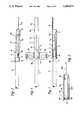
- FIG. 1is a plan view of a preferred embodiment of the inventive apparatus, including a needle, winged needle hub, and slotted needle guard. The needle is in an extended position relative to the needle guard.
- FIG. 2is a partially elevational, partially cross-sectional side view of the FIG. 1 apparatus, in a plane rotated by 90° with respect to the plane of FIG. 1, and with a protector surrounding the extended needle.
- FIG. 3is a side cross-sectional view of the slotted needle guard of the FIG. 1 apparatus.
- FIG. 4is an end view of the FIG. 3 needle guard.
- FIG. 5is a side elevational view of the FIG. 2 apparatus, with the needle locked in a retracted position relative to the needle guard.
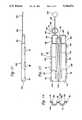
- FIG. 6is a plan view of an alternative embodiment of the inventive apparatus, including a needle, winged needle hub, and slotted needle guard. The needle is in a retracted position relative to the needle guard.
- FIG. 7is a cross-sectional side view of the FIG. 6 apparatus, in a plane rotated by 90° with respect to the plane of FIG. 6.
- FIG. 8is a side cross-sectional view of an another alternative embodiment of the inventive needle guard.
- FIG. 9is a side elevational view of the inventive needle guard in an alternative embodiment of the invention.
- FIG. 10is a side cross-sectional view of the inventive needle guard of FIG. 9.
- FIG. 11is an end view of the FIG. 9 needle guard.
- FIG. 12is a partially side cross-sectional, partially side elevational view of the needle guard of FIG. 10, with a winged hub/needle assembly in a retracted position within the needle guard.
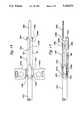
- FIG. 13is a partially side elevational, partially side cross-sectional view of an alternative winged hub/needle assembly of the type useful with the inventive needle guard.
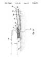
- FIG. 14is a partially side cross-sectional, partially side elevational view of the inventive winged needle guard assembly, with the needle ready to be withdrawn from a patient's skin.
- FIG. 15is a plan view of a preferred slotted needle guard for use with the inventive system, shown in an unassembled, flattened configuration.
- FIG. 16is an end view of the FIG. 15 guard.
- FIG. 17is a side elevational view of the FIG. 15 guard.
- FIG. 18is a plan view of another preferred embodiment of the inventive apparatus, including a slotted, hinged guard, and a sliding needle/hub assembly in a locked, retracted position within the guard.
- FIG. 19is a side cross-sectional view of the FIG. 18 apparatus.
- FIG. 20is a plan view of another preferred embodiment of the inventive apparatus, including a slotted guard with an endcap attached thereto, and a sliding needle/hub assembly in an extended position relative to the guard.
- FIG. 21is a side cross-sectional view of the FIG. 20 apparatus.
- FIG. 22is a side cross-sectional view of the FIG. 20 apparatus, with the sliding needle/hub assembly in a retracted position within the guard and the endcap attached to the guard's right end.
- FIG. 23is a plan view of another preferred embodiment of the inventive apparatus, including a slotted guard, and a sliding needle/hub assembly in an extended position relative to the guard.
- FIG. 24is a cross-sectional view of the FIG. 23 apparatus, taken along line Y--Y of FIG. 23.
- FIG. 25is a side cross-sectional view of the FIG. 23 apparatus, with the sliding needle/hub assembly in a retracted position within the guard.
- FIG. 1generally cylindrical, wingless needle guard 1 encloses a central volume containing part of needle hub 3 (shown partially in phantom view) and part of tube 7 (shown partially in phantom view).
- Tube 7also referred to herein as "tubing" is fixedly attached around first end 3b of hub 3.
- Hollow needle 5is fixedly attached to second end 3c of hub 3.
- Hub 3, needle 5, and tube 7are slidable as a unit relative to guard 1. Needle 5 is in an extended position outside guard 1 in FIG. 1.
- Hollow needle 5is attached to hollow hub 3 in a manner so that fluid may flow between needle 5 and tube 7 through hub 3 (i.e., from within tube 7, through hub 3 and needle 5, and out through tip portion 5a of needle 5, or from within needle 5, through hub 3, and out through tube 7).
- the inventionis particularly useful in the case that needle 5 is an infusion needle.
- Hub 3includes flexible wings 3a, which are typically folded upward (out of the plane of FIG. 1) by the user and gripped in such folded position to insert needle 5 into the skin of a patient. Following insertion of the needle into the patient, wings 3a are typically unfolded and taped to the patient's skin.
- Winged hub 3, needle 5, and tube 7are preferably selected from conventional, commercially available components.
- wings 3awill have thin, flexible portions connecting them to the main, cylindrical body of hub 3, as in many conventional, commercially available winged hub assemblies.
- guard 1The sidewall of guard 1 is cut away to define a pair of narrow slots 1c (only one of slots 1c is shown in FIGS. 2 and 5).
- One of wings 3aextends through each slot 1c, so that slots 1c guide wings 3a as the wings are translated axially relative to guard 1.
- Hub 3, needle 5, and tube 7are preferably assembled in a conventional manner, and needle 5 is then covered by a conventional sterility protector 9 (shown in FIG. 2).
- Guard 1is then attached around the finished needle assembly, so that tip 5a of needle 5 protrudes beyond anchor portion 1a of guard 1. This assembly sequence eliminates the risk that needle 5 or its point 5a will be damaged during assembly.
- wings 3a and slots 1care symmetrical in the embodiment of FIGS. 1-5, in other embodiments the wings (and the slots for receiving them) may not all be symmetrically sized and shaped.
- One slotmay be larger (or shaped differently) than the other slot, whether or not the wings are identical.
- slot 210 between the guard's hinge portions 201amay be shaped differently than slot 211, which is defined by the edges of the guard when such edges meet after portion 201c of the guard is folded relative to portion 201d about hinge portions 201a.
- one wing (and the corresponding slot)may be omitted entirely from the inventive apparatus.
- Protector 9is installed by pressing it over hub 3, and is retained in place by friction between it and the hub. Protector 9 preserves needle 5's sterility prior to an injection. If protector 9 is installed to cover needle 5 before guard 1 is installed around the needle assembly, protector 9 will also protect needle 5 and point 5a during the process of installing guard 1 around the needle assembly. Protector 9 will be removed (in a conventional manner) by a medical worker just prior to a needle injection. Preferably, there will be little or no friction between protector 9 and guard 1, so that translation of the protector from relative to hub 3 (during removal of the protector) will not cause movement of guard 1. Thus, it is desirable (as shown in FIG.
- protector 9may be attached to guard 1 rather than hub 3 and retained in place by friction between it and guard 1.
- Protector 9may also be integrally molded with guard 1, with a break-away portion connecting protector 9 with the rest of guard 1. In this case, guard 1 will maintain its position during removal of protector 9 due to friction exerted by folded wings 3a, which are conventionally gripped in a folded position during this part of the injection procedure.
- the assemblycomprising hub, 3, needle 5, and tube 7 may be pulled toward the left (along the common longitudinal axis of hub, 3, needle 5, tube 7, and guard 1) relative to guard 1 into a retracted, locked position.
- the assemblycomprising hub 3, needle 5, and tube 7 (hereinafter denoted the “sliding assembly”) is shown in its extended position relative to guard 1, in which needle 5 extends beyond guard 1's end portion 1e, guard 1's anchor portion 1a extends angularly away from needle point 5a, and each of wings 3a abuts the rightmost end of one of slots 1c.
- the sliding assemblyis held in such extended position by friction between guard 1 (which may include an interior retaining notch 1b as shown in FIG. 7, or a tab crest 1p as shown in FIGS. 2 and 3) and tube 7, or friction exerted by the walls of slot 1c on wings 3a.
- Such frictionmay be increased by providing a retaining ring or elastic band around the outer surface of guard 1 near flange 1f, or by shaping slots 1c to fit tightly against wings 3a when the sliding assembly is in its extended position.
- the sliding assemblyis shown locked in its retracted position relative to guard 1, in which needle point 5a is retracted within guard 1, each wing 3a is held between shoulders 1h and 1i of one of slots 1c at the slots' left end.
- the sliding assemblycomprising hub 3, needle 5, and tube 7 was translated toward the left relative to guard 1 by gripping anchor portion 1a and pulling tube 7 toward the left relative to guard 1, until wings 3a reached shoulders 1i of slots 1c.
- shoulders 1iprevent further leftward motion of hub 3 relative to guard 1.
- the sliding subassemblyis "irreversibly" slidable in the sense that it may be translated only once from its extended position to its retracted position. Once in its retracted position, it is held therein by action of shoulders 1i and 1h on wings 3a.
- slots 1cextend axially through a substantial portion of guard 1's sidewall, thus dividing guard 1 into an upper part 1m (the part above slot 1c in FIGS. 2 and 3) and a lower part 1k (the part below slot 1c in FIGS. 2 and 3). Lower part 1k may include a protruding tab crest 1p.
- One simple technique for forming slots 1c in guard 1is to mold guard 1 so that slots 1c will extend through an end of guard 1 as shown in FIG. 3.
- guard 1may be molded with slots 1c that do not extend through either end of guard 1 (as will be described below in detail, with reference to FIG. 15-19), or guard 1 may be molded without slots and then the slots may be formed by cutting through either one of guard 1's ends. If slots 1c extend through one of guard 1's ends, however, guard 1 may be undesirably flexible due to bending motion of its upper part 1m relative to its lower part 1k. Such undesirable bending motion will alter the width of each slot 1c by varying the distance between guard 1's lower part 1k and end portions 1j of guard 1's upper part 1m.
- guard 1is preferably shaped so that the upper part end portions 1j form a receptacle into which the left end of lower part 1k may be snapped, so as to interlock the upper part with the lower part 1k as shown in FIG. 2.
- a compression ring(such as ring 10h to be discussed below with reference to FIGS. 9 and 10, or an elastic band) may be positioned around guard 1 to hold the upper and lower parts of guard 1 together, in order to preserve the desired shape of slots 1c, and to ensure locking retention of the sliding assembly within the guard when the sliding assembly is retracted into the guard.
- the needlepreferably has a low profile relative to the patient's skin when the needle penetrates the skin generally parallel to the skin's surface.
- the hub wings and the corresponding guard slotsmay be positioned so that horizontal lines extending through the wings from one slot to the other will be spaced above, below, or coplanar with the horizontal plane through central longitudinal axis 14 of the inventive apparatus.
- wings 3a and slots 1c of FIGS. 2 and 3are positioned as closely as practical to the bottom of these Figures (i.e., as closely as possible given other practical constraints on the size and shape of the system components, for example the thickness of guard 1's side walls).
- wings 3a and slots 1ccould be positioned coplanar with central longitudinal axis 14, or above the plane of central longitudinal axis 14.
- each wing 3a(the portion extending through one of slots 1c) is preferably minimized so that wings 3a may easily be folded vertically by the needle user. It is also desirable that wings 3a have thin inner portions to enable tab crests 1p to bend the wings vertically as the wings slide generally horizontally along slots 1c into engagement with tab crests 1p. Minimizing the vertical thickness of the inner wing portions will allow the corresponding vertical thickness of each slot 1c to be minimized, which will in turn enhance the rigidity of guard 1.
- the end portion 1q of guard 1(in FIGS. 2 and 3) has smaller outer diameter than the rest of guard 1, to facilitate easier bending of the wings 3a when the wings are positioned within the portion of slot 1c at end portion 1q.
- guard 1's anchor 1a(in the embodiment of FIGS. 1-5) is oriented at an angle away from needle 5's axis. With such orientation, anchor 1a will neither impede needle 5's penetration into a patient's skin nor obstruct the user's view of the needle penetration, and anchor 1a may be pressed flat against the patient's skin as the needle is removed from the patient (in a manner to be described below) to cause the needle to retract into guard 1.
- Anchor portion 1amay be rod-shaped (with a round or square-shaped profile) or it may be tubular.
- anchor 1aPreferably, however, it will have a flat profile oriented with flat surfaces in a substantially horizontal plane, as in FIGS. 1, 3, 6, and 7. It is desirable that anchor 1a be flexible and have sufficient length so that it may be positioned flat against a convenient portion of the patient's skin (preferably not precisely over the point of needle entry into the patient) during the needle retraction step.
- anchor 1awill not hinder the operation of rotating a needle mounted within guard 1 (with the needle hub's wings oriented horizontally and extending through slot 1c) by 180° about the guard's axis (clockwise in FIG. 1, from a viewpoint in which needle 5's point 5a points away from the viewer), while the needle remains inserted into the patient.
- Such 180° needle rotationis often desirable during high fluid intake flow rate operations (particularly during hemodialysis).
- anchor 1ahas a flat surface oriented in a substantially horizontal plane vertically spaced from the horizontal plane in which needle 5 lies, so that anchor 1a will not impede needle 5's penetration into a patient's skin as the needle approaches the patient between anchor 1a and the patient's skin.
- anchor 1awill preferably be sufficiently long so that it will extend beyond the needle point 5a when point 5a has been inserted as far as possible into the patient.
- anchor portion 1ahas a flat surface wider than does anchor 1a in FIGS. 1 and 5.
- FIG. 14The operation of removing the needle of the inventive apparatus from a patient will next be described with reference to FIG. 14.
- a medical workerwould follow the conventional procedure of placing gauze 60 against a first region of the patient's skin 80 at the entry point 81 of the needle, and then pressing the gauze with a finger 70 (and/or thumb) of a first hand against such first region of skin while pulling tube 57 (or wings 53a of winged hub 53) of the sliding assembly within slotted guard 50 of the inventive apparatus with the other hand to remove the needle point from within the patient.
- the medical workerwould press the flexible anchor portion of slotted guard 50 (not shown in FIG.
- the anchor portion(not shown in FIG. 14) flat against a second region of the patient's skin 80 with a different finger (or thumb) of the first hand while pressing gauze 60 and pulling the tube (or hub wings) toward the right in a conventional manner.
- the anchor portion(not shown in FIG. 14) is preferably dimensioned and oriented so that it may be pressed against a second region of skin 80 away from the first region. If so, the medical worker may hold guard 50 (including the anchor portion) stationary by pressing the anchor portion against the second skin region with the first hand, while the other hand pulls the sliding assembly toward the right into its retracted position within guard 50 while simultaneously extracting needle 55 from the patient. In this way, the worker is never exposed to the risk of accidentally sticking himself (or herself) with the needle point after the needle point emerges from within the patient.
- anchor 1amay be so short that it does not extend beyond the point 5a of needle 5, or that anchor 1a may be omitted entirely.
- the medical workerwould retract the sliding assembly within guard 1 and simultaneously hold guard 1 stationary by pressing guard 1 (or shortened anchor 1a) against the patient with the same hand (and the same finger or thumb) with which the worker presses the gauze against the patient.
- the riskis greater that manual pressure on guard 1 or anchor 1a will press gauze 60 against the upper portion of the patient's blood vessel in which needle extends, forcing this upper portion of the blood vessel downward against the retracting needle, potentially causing the retracting needle to scrape (and damage) the blood vessel.
- anchor 1ais formed of flexible material, and supplied from the manufacturer in a folded orientation in which it is folded (or bent) backward away from needle point 5a so as not to interfere with insertion of the needle into the patient.
- Anchor 1amay be retained in such folded configuration by any conventional means, such as by removable adhesive tape.
- a medical workerwould unfold the anchor prior to removal of the needle from a patient, and would press the anchor against the patient's skin during needle retraction in the manner described above.
- guard 1includes a different mechanism for locking the subassembly comprising hub 3, needle 5, and tube 7 (the "sliding" assembly) in its retracted position.
- This locking mechanismincludes a retaining notch 1b which extends radially inward from the sidewall of guard 1 near flange 1f. Notch 1b will exert leftward force on end surface 7b of tube 7, thus preventing the sliding assembly from returning to its extended position and retaining the sliding assembly in its retracted position.
- slots 1c in guard 1's side wallare straight; not angled at the left end as in the embodiment of FIGS. 1-5 and 9-12.
- tube 7may be formed conventionally from flexible plastic (such as polyvinyl chloride plastic), so that flexible tube 7 may deform temporarily (i.e., become temporarily indented by action of a rigid notch, such as rigid notch 1b, against tube 7) in order to clear the rigid notch during a transition from the sliding assembly's extended configuration to its retracted configuration.
- flexible plasticsuch as polyvinyl chloride plastic
- Guard 30 of FIG. 8is a cross-sectional side view of an alternative embodiment of the needle guard of the invention.
- Guard 30includes flat anchor portion 30a (having flat, horizontally oriented surfaces), and pair of slots 30c in its side wall (only one of slots 30c is visible in FIG. 8).
- Each slot 30cis substantially straight (as are slots 1c in the embodiment of FIGS. 6-7), in contrast with slots 1c of FIGS. 2 and 3, and slots 10c of FIGS. 9-12 (to be described below).
- Sponge 32shown mounted within guard 30 in a dry, compressed state, is provided for receiving fluid that may drip from a needle after the needle is withdrawn within guard 30 after an injection.
- Ring 34which includes notches 35 and aligning tabs 37, is fixedly attached to the end of guard 30 opposite anchor 30a.
- Each notch 35includes a snap ridge 36 for engaging the end surface 7b of a tube (such as tube 7 of FIGS. 6-7), in the same manner as does notch 1b in FIG. 7, to lock a hub/needle subassembly within guard 30 into its retracted position.
- Each aligning tab 37is oriented and dimensioned to slide within one of slots 30c, so as to properly align ring 34 relative to guard 30 during the operation of attaching ring 34 to guard 30.
- FIGS. 9, 10, 11, and 12show another alternative embodiment of the inventive winged needle guard, including an angled (or curved) slot in its sidewall, rather than a straight slot, and including sponge 12.
- Guard 10's slotincludes a first portion 10c oriented substantially parallel to longitudinal axis 14 of guard 10, and a second portion 10d oriented at an acute angle Z (shown in FIG. 10) relative to axis 14. Angle Z is preferably within the ranges of from about 3° to 4° in the embodiment shown in FIGS. 9 and 10.
- sharp corner 16defines the intersection of portions 10c and 10d in FIGS. 9 and 10, in an alternative embodiment the intersection may instead by defined by a curved slot portion.
- FIG. 11, an end view of FIG. 9,shows that two slot portions 10d are symmetrically positioned on opposite sides of guard 10, for receiving a pair of oppositely oriented hub wings prior to attachment of compression ring 10h around guard 10.
- FIG. 12shows guard 10 of FIGS. 9-11, with a sliding assembly (comprising hub 3, hub wings 3a, needle 5, and tube 7) in a retracted position within needle guard 10.
- a sliding assemblycomprising hub 3, hub wings 3a, needle 5, and tube 7.
- Each wing 3a of hub 3extends through one of slot portions 10d in the FIG. 12 configuration, thus orienting needle 5's longitudinal axis at an angle relative to longitudinal axis 14 of guard 10 so that needle point 5a abuts guard 10's sidewall.
- This retracted needle orientationis desirable in order to maximize the distance between slot 10c and point 5a, and thus reduce the risk that point 5a will protrude out from slot 10c during handling of guard 10 following an injection.
- FIG. 12shows guard 10 of FIGS. 9-11, with a sliding assembly (comprising hub 3, hub wings 3a, needle 5, and tube 7) in a retracted position within needle guard 10.
- Each wing 3a of hub 3extends through one of slot portions 10
- the sliding assemblyis held in its retracted position by the leftward force exerted by notch 10b on end surface 7b of tube 7.
- slot 10cis positioned below the guard's central axis so that needle point 5a abuts the guard's upper sidewall.
- slot 10cwould be angled to cause needle point 5a to abut the guard's lower sidewall (to maximize the distance between the guard and the needle point).
- Sponge 12is mounted within guard 10 to soak up fluids that may drip from needle 5 after an injection, thus reducing the risk that such fluids (such as blood) will drip out of guard 10 and cause infection.
- Sponge 12is shown in its dry compressed state in FIG. 10.
- the small volume of sponge 12 in its dry, compressed stateprovides clearance within guard 10 for mounting a sliding needle/hub assembly (in the sliding assembly's extended position).
- FIG. 12shows sponge 12 in its wet, expanded state.
- a needle/hub subassemblyhas been retracted within guard 10 after an injection, and sponge 12 has expanded due to absorption of fluid dripping from the needle.
- the term "sponge”is used herein to denote a piece of any type of highly absorbent material, including natural sponge material, synthetic sponge material, and other absorbent material.
- Flange 10ffixedly attached outside guard 10 (or integrally molded with guard 10), serves to retain elastic compression ring 10h in place for preventing the upper and lower parts of guard 10 from separating radially.
- Compression ring 10hmay be a rubber band, or another type of elastic band.
- compression ring 10hmay be replaced by a C-shaped or O-shaped rigid ring closure (which may be metal) fixedly attached (such as by a heat seal) to guard 10.
- guard 10is formed of thin polypropylene plastic (i.e., with inner diameter on the order of 5.5 mm, and sidewall thickness on the order of 0.75 mm), and has overall length on the order of 64 mm (from flange 10f to the tip of anchor 10a).
- Anchor 10apreferably has length on the order of 19 millimeters from edge 10e of guard 10 to anchor 10a's tip.
- Flange 10fpreferably has thickness of about 0.75 mm.
- the distance A between beveled edge 10e and the right end of slot 10cis preferably about 3 mm, and the angle Y between retaining notch 10b and axis 14 is preferably 15° .
- the distance D between guard 10's sidewall and the tip of notch 10bis preferably on the order of 0.75 mm.
- the preferred dimensionswill be scaled down.
- needle 5should be mounted so as to have a low profile relative to the patient's skin when needle 5 penetrates the skin generally parallel to the skin's surface.
- Such low needle profileis desirable because the narrow inner diameter of typical needles used with the invention provides great resistance to fluid flow.
- the needle lengthshould be a short as possible (while still long enough to reach a deep vein). Raising the needle profile necessitates use of a longer needle, thus worsening the described flow resistance problems.
- the angle of edge 10e of guard 10helps reduce wasted needle length.
- the length A, between the right end of slot portion 10c and the right end of edge 10e,will ideally be sufficiently long that needle point 5a will rest between the right end of slot portion 10c and the right end of edge 10e when locked in its retracted position. If point 5a is too close to edge 10e, it could accidentally prick an errant finger. If point 5a is adjacent slot portion 10c when locked in its retracted position (as shown in FIG. 12) there is a slight chance that bending of guard 10 might allow point 5a to protrude out through slot portion 10c. It is desirable that such distance A be sufficiently short to avoid unnecessarily limiting the length of needle available for insertion into the patient's skin.
- the wing slot(including portions 10c and 10d) will typically have thickness B substantially equal to 0.75 mm, and the distance C between axis 14 and the upper edge of slot portion 10d at rim 10f will typically be substantially equal to 1.7 mm (where the outer diameter of guard 10 is 7 mm).
- any of the preferred embodiments described hereinmay be scaled up or down to accommodate any needle, for example, any needle having gauge in the range from 12G through 30G.
- FIG. 13shows an alternative winged hub/needle subassembly in a retracted position within slotted needle guard 90.
- the winged hub/needle subassembly of FIG. 13includes needle 25, hub 23, and tube 27.
- Hub 23includes wings 23a.
- Needle 25is fixedly attached to hub 23 in the same manner as needle 5 is attached to hub 3 of FIGS. 1-5 (and hub 3 of the FIG. 6-7 embodiment).
- tube 27is attached to the radially inner surface 23b of hub 23, rather than to the radially outer surface of the hub.
- the hub/needle subassembly of FIG. 13is preferable to that of FIGS. 1-7 for applications in which high fluid flow rates between the tip of the needle (5 or 25) and the tube (7 or 27) are desired.
- Needle guard 90which has an inner diameter slightly greater than the outer diameter of hub 23, is mounted around hub 23 and needle 25.
- a ring-shaped membersuch as ring 28, is fixedly mounted around tube 27 to engage with a locking notch, such as notch 1b of FIG. 7 (or notch 35 of FIG. 8).
- a locking notchsuch as notch 1b of FIG. 7 (or notch 35 of FIG. 8).
- the locking notchi.e., notch 1b of FIG. 7
- Ring 28may be integrally molded with hub 23, or it may be glued or otherwise fixedly attached to hub 23.
- Ring 28 in FIG. 13has non-uniform thickness, with a relatively thicker upper portion 28a and a relatively thinner lower portion 28b.
- the front surface 28c of ring 28is oriented at an acute angle with respect to ring 28's substantially vertical back surface 28d.
- a locking notchsuch as locking notch 1b of FIG. 7
- the force exerted by the notch on ring 28will rotate the FIG. 13 sliding assembly counter-clockwise, so that needle point 25a of retracted needle 25 will point upward, toward the upper sidewall of the guard surrounding retracted needle 25.
- use of an angled slotbecomes unnecessary to ensure that needle point 25a will be positioned away from such slot when the FIG.
- a slotted guard having a non-angled slot(such as guard 30 of FIG. 8, or guard 90 having non-angled slot 90c, as shown in FIG. 13), may be used with the hub/needle assembly of FIG. 13.
- the slotted guard used to enclose the FIG. 13 assemblymay include a notched slot locking mechanism (such as slot 1c of FIGS. 1-5, with shoulders, or “notches,” 1h and 1i) to lock the FIG. 13 assembly in its retracted position within the guard.
- a notched slot locking mechanismsuch as slot 1c of FIGS. 1-5, with shoulders, or “notches,” 1h and 1i
- guard and slotmay be "notchless", as are guard 90 and slot 90c of FIG. 13.
- Guard 90 and ring 28are dimensioned so that the sliding hub/needle assembly may be locked in a retracted position within guard 90 in the following manner.
- ring 28will be enclosed within guard 90 (with ring 28 and the portion of tubing 27 adjacent ring 28 slightly compressed or twisted by the radially inward force exerted thereon by guard 90.
- the hub/needle assemblyis then pulled to the left until ring 28 translates past left end portion 91a of guard 90 and emerges from within guard 90.
- ring 28 and the adjacent portion of tubing 27will relax from their compressed configuration (i.e., they will expand or become untwisted) so that "relaxed" ring 28 will be prevented from reentering guard 90 by action of end portion 91a against ring 28.
- the hub/needle assemblywill remain locked in this "retracted” position (with ring 28 outside, but within a short distance, of guard 90) due to the force exerted on wing 23a of hub 23 by the left end 90d of guard 90.
- Endcap 93 of FIG. 13is another optional feature of the invention, which may be attached to (or integrally molded with) the anchor of any of the inventive embodiments.
- flexible anchor 92is attached to guard 90
- endcap 93is attached to anchor 92.
- Endcap 93comprises a disk (having outer portion 95 and inner portion 96), and a ridge 94 separating portions 95 and 96.
- Guard 100includes hinge portion 102 (connecting two generally half-cylindrical portions 140 and 141). Locking tabs 110, 112, and 114 protrude from an edge of portion 140. Locking tabs 116, 118, and 120 protrude from an edge of portion 141.
- An anchorcomprising anchor stem 122, flat anchor plate 124, and flat endcap 150, is attached to end portion 101 of guard 100. Endcap 150 includes inner and outer disk portions 152 and 153, and circular ridge 151 separating portions 152 and 153.
- Hub wing slots 105 and 106having notched portions 107 and 108 respectively, extend through guard 100. Slots 105 and 106 are formed during the process of molding flat, unassembled guard 100.
- Guard 100is molded in a generally flat, open configuration as shown in FIGS. 15-17.
- the hub wings protruding out from such assemblyare extended through slots 105 and 106, and portions 140 and 141 of guard 100 are then folded together about hinge portion 102 to enclose the hub/needle assembly, and so that tab 116 locks between tabs 112 and 114, tab 118 locks between tabs 110 and 112, and tab 110 locks between tabs 118 and 120.
- Tabs 110, 112, 114, 116, 118, and 120thus lock together to retain guard 100 in its assembled configuration.
- guard 100When locked in its assembled configuration, guard 100 has a generally cylindrical shape, with its longitudinal cylinder axis parallel to anchor stem 122. If the plane of anchor plate 124 is defined as the horizontal plane, then when guard 100 has been folded and locked in its cylindrical, assembled configuration, the plane intersecting hinge 102 and locked tabs 110, 112, 114, 116, 118, and 120 is oriented substantially vertically, and hinge 102 extends horizontally along the bottom of assembled guard 100.
- Tabs 130 and 132extend (vertically out of the plane of FIG. 15) from guard 100's end portion 103, and slots 131 and 133 extend through guard 100's end portion 101. Tabs 130 and 132 are sized and positioned to fit tightly within slots 131 and 133, respectively, when guard 100 is folded into its cylindrical assembled configuration. Friction between tabs 130 and 132 and the walls of slots 131 and 133 helps to maintain guard in its cylindrical assembled configuration.
- anchor plate 124may be pressed against a patient's skin during the operation of needle withdrawal from the patient, to allow the needle to translate into a locked, retracted position within assembled guard 100.
- Anchor stem 122is desirably flexible to permit convenient positioning of plate 124 and to permit endcap 150 to be snapped together with guard 100's right end (with ridge 151 locked inside the inner cylindrical surface of guard 100's sidewall).
- FIGS. 18 and 19show yet another preferred embodiment of the inventive apparatus.
- Hub 203has two wings 203a, one extending through slot 210 in the sidewall of guard 201 and the other extending through slot 211 in the sidewall of guard 201.
- Tubing 207is attached around one end of hub 203, and needle 205 is attached to the other end of hub 203.
- the entire assembly comprising hub 203, needle 205, and tubing 207is slidably mounted within guard 201. If tubing 207 or wings 203a are pulled toward the left from an extended position (with needle 205's point outside guard 201), hub 203 and needle 205 will translate toward the left as they retract into guard 201.
- hub 203occupies the position shown in FIGS.
- Guard 201is preferably dimensioned as shown, to accommodate a variety of the most commonly used conventional needles.
- needle 205is a conventional needle having a length of one inch
- needle 205's pointwill occupy position 205a
- needle 205is a conventional needle having a length of one and one quarter inches
- needle 205's pointwill occupy position 205b. Both needle point positions 205a and 205b are safely within guard 201 when the needle is locked in its retracted position.
- Anchor portion 202 of guard 201has a flat surface lying in the plane of FIG. 18.
- Guard 201is preferably molded in a generally flat, one-piece, unassembled configuration. Guard 201 attains its generally cylindrical shape (shown in FIGS. 18 and 19) only after generally half-cylindrical portions 201c and 201d of guard 201 are folded together about side hinge portions 201a and the edges of portions 201c and 201d are sealed together at sealing regions 201b.
- guard 201To install guard 201 around the sliding hub/needle assembly, the upper one of hub wings 203a is extended through slot 210 between side hinge portions 201a, and first portion 201c of guard 201 is then folded about hinge portions 201a relative to second portion 201d of 201, so that the edges of portions 201c and 201d meet at side sealing regions 201b. As the edges of portions 201c and 201d meet, they define second slot 211. Slot 211 is thus formed around the lower one of wings 203a during the operation of folding portion 201c about hinge portions 201a, so that such lower wing extends through the newly formed slot 211.
- the edges of portions 201c and 210dmay be shaped so as to define a slot 211 identical to slot 210.
- portions 201c and 201dmay be shaped so as to define a slot 211 shaped differently from slot 210 (for example, the central portion of slot 211 may be narrower than that of slot 210, where slot 210 has a wide central portion to facilitate easier insertion of the upper wing 203a through slot 210).
- portion 201cis fixedly attached by a heat seal (or an adhesive layer, or snaps) to portion 201d in order to maintain guard 201 in the cylindrical assembled configuration shown in FIGS. 18 and 19.
- a heat sealor an adhesive layer, or snaps
- one or more locking tabsmay protrude from the edges of either or both of portions 201c and 201d, to enable portions 201c and 201d to be snapped together (and remain snapped together by friction) at regions 201b.
- Portions 201c and 201dneed not include locking tabs, but may be otherwise shaped so that they will snap together (and remain held together by friction) at regions 201b.
- hinge portions 201aare omitted from guard 201, so that guard 201 consists of two separate, generally half-cylindrical portions 201c and 201d.
- the half-cylindrical portionsare connected together (by a heat seal, by an adhesive layer, or by snapping together) at all four of regions 201a and 201b.
- slot 210is formed as an orifice through the hinge region of one-piece guard 201 between hinge portions 201a during the molding process (in the same manner as slots 105 and 106 are formed in one-piece guard 100 shown in FIG. 15).
- Slot 211(which is not shown in FIG. 19, but which is positioned symmetrically on the side of guard 201 opposite slot 210 as shown in FIG. 18) is a gap between the connected edges of portions 201c and 201d which is bounded at the ends by regions 201b.
- both slots of the two-piece guard described in the preceding paragraphare defined by the connected edge portions of the guard's half-cylindrical component members between sealing regions 201a and 201b (in other words, one slot is a gap between the connected edges between regions 201a, and the other slot is a gap between the connected edges between regions 201b).
- no slot orificeneed be formed through either half-cylindrical guard portion during the operation of molding the half-cylindrical guard portions.
- FIGS. 20-22show another preferred embodiment of the invention.
- the FIG. 18 sliding assembly(comprising winged hub 203, needle 205, and tubing 207) is mounted within slotted guard 301.
- Flexible anchor stem 302connects endcap 303 with guard 301.
- Endcap 303is employed as an anchor in the same manner as anchor 124 of FIG. 15.
- Member 303also functions as an endcap, which may be snapped onto guard 301's right end as shown in FIG. 22.
- Endcap 303includes disk portion 304 and generally cylindrical wall portion 305.
- wall portion 305may be snapped over the outside of guard 301's sidewall so that endcap 303 prevents fluid flow from needle 205 out through the right end of guard 301.
- FIGS. 23-25show another preferred embodiment of the invention.
- the FIG. 18 sliding assembly(comprising winged hub 203, needle 205, and tubing 207) is mounted within slotted guard 401.
- Anchor portion 402 of guard 401is oriented in the plane of hub 203's wings 203a.
- a pair of slots 401cextend through the sidewall of guard 401 to receive wings 203a.
- guard 401's sidewallis molded to have curtain portions 403.
- Curtain portions 403normally fit tightly against lower sidewall 401a of guard 401 (which defines the lower edge of slots 401c), as shown in FIG.
- Each curtain 403forms the upper edge of the central portions of one of slots 401c, and thus curtains 403 may be displaced from lower guard portion 401a by wings 203a to allow wings 203a to pass through such central slot portions (as shown in FIGS. 23 and 24).
- wings 203adisplace curtains 403 radially outward with respect to the lower guard portion 401a (and thus radially outward with respect to the lower slot edges defined by portion 401a).
- curtains 403could be shaped so that wings 203a will displace curtains 403 radially inward with respect to the lower guard portion 401a.
- each slot 401c(not just the central portion of such edge) is shaped so as to form one of curtains 403.
- the slotsare sealed by pressing the upper slot edges (curtains 403) into a locked configuration against lower guard portion 401a (which defines the lower slot edges).
- the upper and lower slot edges in this embodimentwould preferably have the same shapes as do the lips of conventional press-sealable plastic sandwich bags.
- Wings 203awould temporarily break apart (unseal) the slots as they translate through the slots during a transition from hub 203's extended position into hub 203's retracted position. After hub 203 and wings 203a have reached their fully retracted position, the slots would be resealed by pressing curtains 403 against lower guard portion 401a.
- the inventionmay be manufactured using conventional winged needle assembly technology, and may be operated by medical personnel in a conventional manner with the simple additional step of holding the inventive guard fixed during extraction of the needle from a patient (such as by pressing the guard's anchor against a patient with one finger while simultaneously pressing gauze against the patient, in a conventional manner, with another digit of the same hand).
Landscapes
- Health & Medical Sciences (AREA)
- Life Sciences & Earth Sciences (AREA)
- Biophysics (AREA)
- Pulmonology (AREA)
- Engineering & Computer Science (AREA)
- Anesthesiology (AREA)
- Biomedical Technology (AREA)
- Heart & Thoracic Surgery (AREA)
- Hematology (AREA)
- Animal Behavior & Ethology (AREA)
- General Health & Medical Sciences (AREA)
- Public Health (AREA)
- Veterinary Medicine (AREA)
- Infusion, Injection, And Reservoir Apparatuses (AREA)
Abstract
Description
Claims (7)
Priority Applications (2)
| Application Number | Priority Date | Filing Date | Title |
|---|---|---|---|
| US07/948,348US5266072A (en) | 1988-09-30 | 1992-09-21 | Guarded winged needle assembly |
| US08/198,348US5433703A (en) | 1988-09-30 | 1994-02-18 | Guarded winged needle assembly |
Applications Claiming Priority (4)
| Application Number | Priority Date | Filing Date | Title |
|---|---|---|---|
| US25256488A | 1988-09-30 | 1988-09-30 | |
| US07/562,419US5112311A (en) | 1988-09-30 | 1990-07-30 | Guarded winged needle assembly |
| US76144391A | 1991-09-18 | 1991-09-18 | |
| US07/948,348US5266072A (en) | 1988-09-30 | 1992-09-21 | Guarded winged needle assembly |
Related Parent Applications (2)
| Application Number | Title | Priority Date | Filing Date |
|---|---|---|---|
| US07/562,419DivisionUS5112311A (en) | 1988-09-30 | 1990-07-30 | Guarded winged needle assembly |
| US76144391AContinuation | 1988-09-30 | 1991-09-18 |
Related Child Applications (1)
| Application Number | Title | Priority Date | Filing Date |
|---|---|---|---|
| US6107993ADivision | 1988-09-30 | 1993-05-14 |
Publications (1)
| Publication Number | Publication Date |
|---|---|
| US5266072Atrue US5266072A (en) | 1993-11-30 |
Family
ID=27500430
Family Applications (1)
| Application Number | Title | Priority Date | Filing Date |
|---|---|---|---|
| US07/948,348Expired - LifetimeUS5266072A (en) | 1988-09-30 | 1992-09-21 | Guarded winged needle assembly |
Country Status (1)
| Country | Link |
|---|---|
| US (1) | US5266072A (en) |
Cited By (51)
| Publication number | Priority date | Publication date | Assignee | Title |
|---|---|---|---|---|
| US5354281A (en)* | 1994-03-25 | 1994-10-11 | Chen Shih Shuan | Safety disposable infusion set |
| US5498241A (en)* | 1994-12-08 | 1996-03-12 | Abbott Laboratories | Winged needle assembly with protective member |
| US5501672A (en)* | 1990-05-09 | 1996-03-26 | Safety Syringes, Inc. | Disposable self-shielding hypodermic syringe |
| US5505711A (en)* | 1994-01-21 | 1996-04-09 | Nissho Corporation | Indwelling injector needle assembly having wings |
| US5549571A (en)* | 1995-04-18 | 1996-08-27 | Sak; Robert F. | Butterfly assembly with retractable needle cannula |
| US5624400A (en)* | 1990-05-09 | 1997-04-29 | Safety Syringes, Inc. | Disposable self-shielding aspirating syringe |
| US5704924A (en)* | 1996-01-11 | 1998-01-06 | Medisystems Technology Corporation | Easy use needle protector sheath |
| US5718239A (en)* | 1996-06-21 | 1998-02-17 | Becton, Dickinson And Company | Method of activating a needle assembly having a telescoping shield |
| US5755699A (en)* | 1990-11-08 | 1998-05-26 | Mbo Laboratories, Inc. | Safety needle system assuring hazard-free handling after needle contamination |
| US5858004A (en)* | 1996-08-19 | 1999-01-12 | Shields; Jack W. | Head projections on shielded butterfly needle assemblies |
| US5951525A (en)* | 1998-02-10 | 1999-09-14 | Specialized Health Products, Inc. | Manual safety medical needle apparatus and methods |
| US5993426A (en)* | 1993-04-16 | 1999-11-30 | Sims Portex Inc. | Fluid absorbable needle sheath |
| US6050976A (en)* | 1998-12-23 | 2000-04-18 | Specialized Health Products, Inc. | In-line retractable safety catheter needle insertion assembly |
| US6197007B1 (en) | 1999-02-04 | 2001-03-06 | David L. Thorne | In-line retractable safety medical needle assembly |
| US20020188260A1 (en)* | 2001-06-07 | 2002-12-12 | Peter Gollobin | Protective sheath for winged needles and sheath and needle assembly |
| USD471979S1 (en) | 2002-03-19 | 2003-03-18 | Becton, Dickinson And Company | Needle assembly |
| USD475783S1 (en) | 2002-05-23 | 2003-06-10 | Becton, Dickinson And Company | Needle assembly |
| US20030163096A1 (en)* | 2002-02-28 | 2003-08-28 | Becton, Dickinson And Company | Shieldable fluid collection set |
| US6623461B1 (en) | 2002-03-15 | 2003-09-23 | Becton, Dickinson And Company | Forward shielding safety device |
| US20030181869A1 (en)* | 2002-03-20 | 2003-09-25 | Becton, Dickinson And Company | Needle assembly |
| US20030181874A1 (en)* | 2002-03-20 | 2003-09-25 | Becton, Dickinson And Company | Blood collection device |
| US20030181870A1 (en)* | 2002-03-19 | 2003-09-25 | Becton, Dickinson And Company | Needle device |
| US20030181872A1 (en)* | 2002-03-19 | 2003-09-25 | Becton, Dickinson And Company | Needle device |
| US20030181871A1 (en)* | 2002-03-19 | 2003-09-25 | Becton, Dickinson And Company | Needle assembly |
| US20030181867A1 (en)* | 2002-03-19 | 2003-09-25 | Becton, Dickinson And Company | Needle assembly |
| US6632201B1 (en) | 1999-11-17 | 2003-10-14 | Baxter International Inc. | Locking needle protector |
| US20030216687A1 (en)* | 2002-05-15 | 2003-11-20 | Becton Dickinson & Company | Blood collection device |
| US20040102739A1 (en)* | 2000-10-06 | 2004-05-27 | Masakuni Nakajima | Wing retraction type mis-piercing preventer and winged needle having the mis-piercing preventer |
| US6984223B2 (en) | 2001-11-13 | 2006-01-10 | Becton, Dickinson And Company | Needle safety device |
| US6997913B2 (en) | 2002-06-07 | 2006-02-14 | Becton, Dickinson And Company | Needle safety device |
| US20060079847A1 (en)* | 2004-07-01 | 2006-04-13 | Becton, Dickinson And Company | Forward-shielding blood collection set |
| US7048718B1 (en) | 1999-09-27 | 2006-05-23 | Jms Co., Ltd | Winged injection needle having needle covering means |
| US20070118082A1 (en)* | 2003-03-20 | 2007-05-24 | Takeshi Mori | Assembly of winged needle and protector sheath for winged needle |
| US7294118B2 (en) | 2001-10-24 | 2007-11-13 | Becton, Dickinson And Company | Retractable needle assembly |
| US20080306452A1 (en)* | 2004-07-01 | 2008-12-11 | Becton, Dickinson And Company | Passively Shielding Needle Device |
| US7566327B2 (en) | 2002-08-09 | 2009-07-28 | Fenwal, Inc. | Needle protector |
| US20090198214A1 (en)* | 2008-02-01 | 2009-08-06 | Istvan Bognar | Butterfly Needle Devices and Methods Relating Thereto |
| WO2010038844A1 (en) | 2008-10-01 | 2010-04-08 | Kawasumi Laboratories, Inc. | Anti-needlestick system |
| US8323251B2 (en) | 2008-01-14 | 2012-12-04 | Fenwal, Inc. | Phlebotomy needle assembly and frangible cover |
| US8372044B2 (en) | 2005-05-20 | 2013-02-12 | Safety Syringes, Inc. | Syringe with needle guard injection device |
| US8439870B2 (en) | 2008-09-10 | 2013-05-14 | B. Braun Medical Inc. | Safety needle assembly and methods |
| US8486024B2 (en) | 2011-04-27 | 2013-07-16 | Covidien Lp | Safety IV catheter assemblies |
| US8628497B2 (en) | 2011-09-26 | 2014-01-14 | Covidien Lp | Safety catheter |
| US8715250B2 (en) | 2011-09-26 | 2014-05-06 | Covidien Lp | Safety catheter and needle assembly |
| US8834422B2 (en) | 2011-10-14 | 2014-09-16 | Covidien Lp | Vascular access assembly and safety device |
| US8939938B2 (en) | 2006-10-12 | 2015-01-27 | Covidien Lp | Needle tip protector |
| WO2015015547A1 (en) | 2013-07-29 | 2015-02-05 | 川澄化学工業株式会社 | Needle cover and winged needle with needle cover |
| US10350366B2 (en) | 2013-02-01 | 2019-07-16 | Nxstage Medical, Inc. | Safe cannulation devices, methods, and systems |
| US11083841B2 (en) | 2002-08-09 | 2021-08-10 | Fenwal, Inc. | Needle protector, needle assembly and fluid processing set including the same |
| US11324928B2 (en)* | 2013-02-05 | 2022-05-10 | Greiner Bio-One Gmbh | Needle assembly |
| US11890459B2 (en) | 2020-03-27 | 2024-02-06 | Medivena Sp. Z O.O. | Needle-based device with external safety cap and a needle guide element thereof |
Citations (25)
| Publication number | Priority date | Publication date | Assignee | Title |
|---|---|---|---|---|
| CA729419A (en)* | 1966-03-08 | Gingras Pierre | Hypodermic injection syringe | |
| US3323523A (en)* | 1964-11-18 | 1967-06-06 | Abbott Lab | Intravenous catheter assembly with divisible needle sheath portions |
| US3463152A (en)* | 1966-06-08 | 1969-08-26 | Sorenson Research Corp | Catheter placement unit |
| US3568673A (en)* | 1968-11-04 | 1971-03-09 | Bard Inc C R | Needle bevel guard for intravenous catheter |
| US3572334A (en)* | 1968-11-27 | 1971-03-23 | Johnson & Johnson | Intravenous catheter placement unit |
| US3595230A (en)* | 1968-07-25 | 1971-07-27 | Abbott Lab | Intravenous catheter placement unit with tubular guide sheath |
| US3610240A (en)* | 1967-06-13 | 1971-10-05 | American Hospital Supply Corp | Intravenous catheter apparatus with catheter telescoped inside puncturing cannula |
| US4068659A (en)* | 1976-07-12 | 1978-01-17 | Deseret Pharmaceutical Co., Inc. | Catheter placement assembly |
| US4329989A (en)* | 1981-02-23 | 1982-05-18 | Edsyn, Inc. | Liquid dispenser |
| US4425120A (en)* | 1982-04-15 | 1984-01-10 | Sampson Norma A | Shielded hypodermic syringe |
| US4573976A (en)* | 1984-05-24 | 1986-03-04 | Dolores A. Smith | Shielded needle |
| US4631057A (en)* | 1985-12-17 | 1986-12-23 | Dolores A. Smith | Shielded needle |
| US4643722A (en)* | 1983-04-05 | 1987-02-17 | Smith Jr William I | Closure system for storage, transport and disposal of hypodermic needles |
| US4664654A (en)* | 1986-03-07 | 1987-05-12 | Strauss Eric C | Automatic protracting and locking hypodermic needle guard |
| US4676783A (en)* | 1985-09-03 | 1987-06-30 | The University Of Virginia Alumni Patents Foundation | Retractable safety needle |
| US4693708A (en)* | 1986-10-16 | 1987-09-15 | Wanderer Alan A | Combination needle shield/needle guard device for a hypodermic syringe with a permanently attached needle |
| US4731059A (en)* | 1986-10-14 | 1988-03-15 | Medical Safety Products, Inc. | Combination needle shield/needle guard device positively locked onto detachable needle assemblies for an evacuated blood collection system and a hypodermic syringe |
| US4747836A (en)* | 1987-07-17 | 1988-05-31 | Luther Medical Products, Inc. | Needle guard, and assembly |
| US4790828A (en)* | 1987-08-07 | 1988-12-13 | Dombrowski Mitchell P | Self-capping needle assembly |
| US4820282A (en)* | 1986-10-20 | 1989-04-11 | City Of Hope National Medical Center | Sheath for butterfly needles |
| US4840619A (en)* | 1988-05-26 | 1989-06-20 | Hughes Elaine L | Syringe |
| US4842587A (en)* | 1987-07-15 | 1989-06-27 | Poncy George W | No-prick hypodermic syringe |
| US4874383A (en)* | 1987-03-17 | 1989-10-17 | Mcnaughton R David | Syringe shield |
| US4888001A (en)* | 1988-06-01 | 1989-12-19 | Schoenberg Stephen J | Cover for a disposable hypodermic needle |
| US4935012A (en)* | 1988-06-10 | 1990-06-19 | George R. Magre | Safety device for medical needles |
- 1992
- 1992-09-21USUS07/948,348patent/US5266072A/ennot_activeExpired - Lifetime
Patent Citations (25)
| Publication number | Priority date | Publication date | Assignee | Title |
|---|---|---|---|---|
| CA729419A (en)* | 1966-03-08 | Gingras Pierre | Hypodermic injection syringe | |
| US3323523A (en)* | 1964-11-18 | 1967-06-06 | Abbott Lab | Intravenous catheter assembly with divisible needle sheath portions |
| US3463152A (en)* | 1966-06-08 | 1969-08-26 | Sorenson Research Corp | Catheter placement unit |
| US3610240A (en)* | 1967-06-13 | 1971-10-05 | American Hospital Supply Corp | Intravenous catheter apparatus with catheter telescoped inside puncturing cannula |
| US3595230A (en)* | 1968-07-25 | 1971-07-27 | Abbott Lab | Intravenous catheter placement unit with tubular guide sheath |
| US3568673A (en)* | 1968-11-04 | 1971-03-09 | Bard Inc C R | Needle bevel guard for intravenous catheter |
| US3572334A (en)* | 1968-11-27 | 1971-03-23 | Johnson & Johnson | Intravenous catheter placement unit |
| US4068659A (en)* | 1976-07-12 | 1978-01-17 | Deseret Pharmaceutical Co., Inc. | Catheter placement assembly |
| US4329989A (en)* | 1981-02-23 | 1982-05-18 | Edsyn, Inc. | Liquid dispenser |
| US4425120A (en)* | 1982-04-15 | 1984-01-10 | Sampson Norma A | Shielded hypodermic syringe |
| US4643722A (en)* | 1983-04-05 | 1987-02-17 | Smith Jr William I | Closure system for storage, transport and disposal of hypodermic needles |
| US4573976A (en)* | 1984-05-24 | 1986-03-04 | Dolores A. Smith | Shielded needle |
| US4676783A (en)* | 1985-09-03 | 1987-06-30 | The University Of Virginia Alumni Patents Foundation | Retractable safety needle |
| US4631057A (en)* | 1985-12-17 | 1986-12-23 | Dolores A. Smith | Shielded needle |
| US4664654A (en)* | 1986-03-07 | 1987-05-12 | Strauss Eric C | Automatic protracting and locking hypodermic needle guard |
| US4731059A (en)* | 1986-10-14 | 1988-03-15 | Medical Safety Products, Inc. | Combination needle shield/needle guard device positively locked onto detachable needle assemblies for an evacuated blood collection system and a hypodermic syringe |
| US4693708A (en)* | 1986-10-16 | 1987-09-15 | Wanderer Alan A | Combination needle shield/needle guard device for a hypodermic syringe with a permanently attached needle |
| US4820282A (en)* | 1986-10-20 | 1989-04-11 | City Of Hope National Medical Center | Sheath for butterfly needles |
| US4874383A (en)* | 1987-03-17 | 1989-10-17 | Mcnaughton R David | Syringe shield |
| US4842587A (en)* | 1987-07-15 | 1989-06-27 | Poncy George W | No-prick hypodermic syringe |
| US4747836A (en)* | 1987-07-17 | 1988-05-31 | Luther Medical Products, Inc. | Needle guard, and assembly |
| US4790828A (en)* | 1987-08-07 | 1988-12-13 | Dombrowski Mitchell P | Self-capping needle assembly |
| US4840619A (en)* | 1988-05-26 | 1989-06-20 | Hughes Elaine L | Syringe |
| US4888001A (en)* | 1988-06-01 | 1989-12-19 | Schoenberg Stephen J | Cover for a disposable hypodermic needle |
| US4935012A (en)* | 1988-06-10 | 1990-06-19 | George R. Magre | Safety device for medical needles |
Cited By (86)
| Publication number | Priority date | Publication date | Assignee | Title |
|---|---|---|---|---|
| US5624400A (en)* | 1990-05-09 | 1997-04-29 | Safety Syringes, Inc. | Disposable self-shielding aspirating syringe |
| US5501672A (en)* | 1990-05-09 | 1996-03-26 | Safety Syringes, Inc. | Disposable self-shielding hypodermic syringe |
| USRE37439E1 (en)* | 1990-05-09 | 2001-11-06 | Safety Syringes, Inc. | Disposable self-shielding aspirating syringe |
| US5755699A (en)* | 1990-11-08 | 1998-05-26 | Mbo Laboratories, Inc. | Safety needle system assuring hazard-free handling after needle contamination |
| USRE36885E (en)* | 1990-11-08 | 2000-09-26 | Mbo Laboratories, Inc. | Safety needle system assuring hazard-free handling after needle contamination |
| US5993426A (en)* | 1993-04-16 | 1999-11-30 | Sims Portex Inc. | Fluid absorbable needle sheath |
| US5505711A (en)* | 1994-01-21 | 1996-04-09 | Nissho Corporation | Indwelling injector needle assembly having wings |
| US5354281A (en)* | 1994-03-25 | 1994-10-11 | Chen Shih Shuan | Safety disposable infusion set |
| US5498241A (en)* | 1994-12-08 | 1996-03-12 | Abbott Laboratories | Winged needle assembly with protective member |
| US5549571A (en)* | 1995-04-18 | 1996-08-27 | Sak; Robert F. | Butterfly assembly with retractable needle cannula |
| US5704924A (en)* | 1996-01-11 | 1998-01-06 | Medisystems Technology Corporation | Easy use needle protector sheath |
| US5893845A (en)* | 1996-06-21 | 1999-04-13 | Becton Dickinson & Company | Telescoping needle shield |
| US5718239A (en)* | 1996-06-21 | 1998-02-17 | Becton, Dickinson And Company | Method of activating a needle assembly having a telescoping shield |
| US5858004A (en)* | 1996-08-19 | 1999-01-12 | Shields; Jack W. | Head projections on shielded butterfly needle assemblies |
| US5951525A (en)* | 1998-02-10 | 1999-09-14 | Specialized Health Products, Inc. | Manual safety medical needle apparatus and methods |
| US6050976A (en)* | 1998-12-23 | 2000-04-18 | Specialized Health Products, Inc. | In-line retractable safety catheter needle insertion assembly |
| US6197007B1 (en) | 1999-02-04 | 2001-03-06 | David L. Thorne | In-line retractable safety medical needle assembly |
| US7048718B1 (en) | 1999-09-27 | 2006-05-23 | Jms Co., Ltd | Winged injection needle having needle covering means |
| US6632201B1 (en) | 1999-11-17 | 2003-10-14 | Baxter International Inc. | Locking needle protector |
| US7153293B2 (en) | 2000-10-06 | 2006-12-26 | Jms Co., Ltd | Wing retraction type mis-piercing preventer and winged needle having the mis-piercing preventer |
| US20040102739A1 (en)* | 2000-10-06 | 2004-05-27 | Masakuni Nakajima | Wing retraction type mis-piercing preventer and winged needle having the mis-piercing preventer |
| US6824527B2 (en)* | 2001-06-07 | 2004-11-30 | Peter Gollobin | Protective sheath for winged needles and sheath and needle assembly |
| US20020188260A1 (en)* | 2001-06-07 | 2002-12-12 | Peter Gollobin | Protective sheath for winged needles and sheath and needle assembly |
| US7294118B2 (en) | 2001-10-24 | 2007-11-13 | Becton, Dickinson And Company | Retractable needle assembly |
| USRE43473E1 (en) | 2001-11-13 | 2012-06-12 | Becton, Dickinson And Company | Needle safety device |
| US6984223B2 (en) | 2001-11-13 | 2006-01-10 | Becton, Dickinson And Company | Needle safety device |
| US20030163096A1 (en)* | 2002-02-28 | 2003-08-28 | Becton, Dickinson And Company | Shieldable fluid collection set |
| US6623461B1 (en) | 2002-03-15 | 2003-09-23 | Becton, Dickinson And Company | Forward shielding safety device |
| US7060055B2 (en) | 2002-03-15 | 2006-06-13 | Becton Dickinson And Company | Forward shielding safety device |
| USD471979S1 (en) | 2002-03-19 | 2003-03-18 | Becton, Dickinson And Company | Needle assembly |
| US20030181867A1 (en)* | 2002-03-19 | 2003-09-25 | Becton, Dickinson And Company | Needle assembly |
| US20030181871A1 (en)* | 2002-03-19 | 2003-09-25 | Becton, Dickinson And Company | Needle assembly |
| US6926700B2 (en) | 2002-03-19 | 2005-08-09 | Becton, Dickinson And Company | Needle assembly |
| US6932803B2 (en) | 2002-03-19 | 2005-08-23 | Becton, Dickinson And Company | Needle device |
| US20030181872A1 (en)* | 2002-03-19 | 2003-09-25 | Becton, Dickinson And Company | Needle device |
| US20030181870A1 (en)* | 2002-03-19 | 2003-09-25 | Becton, Dickinson And Company | Needle device |
| US20070021723A1 (en)* | 2002-03-20 | 2007-01-25 | Becton, Dickinson And Company | Blood Collection Device |
| US8182451B2 (en) | 2002-03-20 | 2012-05-22 | Becton, Dickinson And Company | Blood collection device |
| US8425472B2 (en) | 2002-03-20 | 2013-04-23 | Becton, Dickinson And Company | Blood collection device |
| US7112190B2 (en) | 2002-03-20 | 2006-09-26 | Becton, Dickinson And Company | Blood collection device |
| US8708977B2 (en) | 2002-03-20 | 2014-04-29 | Becton, Dickinson And Company | Blood collection device |
| US20070016147A1 (en)* | 2002-03-20 | 2007-01-18 | Becton, Dickinson And Company | Blood Collection Device |
| US20030181874A1 (en)* | 2002-03-20 | 2003-09-25 | Becton, Dickinson And Company | Blood collection device |
| US20070021722A1 (en)* | 2002-03-20 | 2007-01-25 | Becton, Dickinson And Company | Blood Collection Device |
| US20070021724A1 (en)* | 2002-03-20 | 2007-01-25 | Becton, Dickinson And Company | Blood Collection Device |
| US7833198B2 (en) | 2002-03-20 | 2010-11-16 | Becton, Dickinson And Company | Blood collection device |
| US7803138B2 (en) | 2002-03-20 | 2010-09-28 | Becton, Dickinson And Company | Blood collection device |
| US20070197979A1 (en)* | 2002-03-20 | 2007-08-23 | Becton, Dickinson And Company | Blood Collection Device |
| US20030181869A1 (en)* | 2002-03-20 | 2003-09-25 | Becton, Dickinson And Company | Needle assembly |
| US7578805B2 (en) | 2002-05-15 | 2009-08-25 | Becton, Dickinson And Company | Blood collection device |
| US20030216687A1 (en)* | 2002-05-15 | 2003-11-20 | Becton Dickinson & Company | Blood collection device |
| USD475783S1 (en) | 2002-05-23 | 2003-06-10 | Becton, Dickinson And Company | Needle assembly |
| US6997913B2 (en) | 2002-06-07 | 2006-02-14 | Becton, Dickinson And Company | Needle safety device |
| US7566327B2 (en) | 2002-08-09 | 2009-07-28 | Fenwal, Inc. | Needle protector |
| US11083841B2 (en) | 2002-08-09 | 2021-08-10 | Fenwal, Inc. | Needle protector, needle assembly and fluid processing set including the same |
| US7326189B2 (en) | 2003-03-20 | 2008-02-05 | Nipro Corporation | Assembly of winged needle and protector sheath for winged needle |
| US20070118082A1 (en)* | 2003-03-20 | 2007-05-24 | Takeshi Mori | Assembly of winged needle and protector sheath for winged needle |
| US9402964B2 (en) | 2004-07-01 | 2016-08-02 | Becton, Dickinson And Company | Passively shielding needle device |
| US8500690B2 (en) | 2004-07-01 | 2013-08-06 | Becton, Dickinson And Company | Passively shielding needle device |
| US7201740B2 (en) | 2004-07-01 | 2007-04-10 | Becton, Dickinson And Company | Forward-shielding blood collection set |
| US9878130B2 (en) | 2004-07-01 | 2018-01-30 | Becton, Dickinson And Company | Passively shielding needle device |
| US20060079847A1 (en)* | 2004-07-01 | 2006-04-13 | Becton, Dickinson And Company | Forward-shielding blood collection set |
| US20080306452A1 (en)* | 2004-07-01 | 2008-12-11 | Becton, Dickinson And Company | Passively Shielding Needle Device |
| EP2705864A2 (en) | 2004-07-01 | 2014-03-12 | Becton, Dickinson and Company | Passively shielding needle device |
| EP2705865A2 (en) | 2004-07-01 | 2014-03-12 | Becton, Dickinson and Company | Passively shielding needle device |
| US8372044B2 (en) | 2005-05-20 | 2013-02-12 | Safety Syringes, Inc. | Syringe with needle guard injection device |
| US8939938B2 (en) | 2006-10-12 | 2015-01-27 | Covidien Lp | Needle tip protector |
| US8323251B2 (en) | 2008-01-14 | 2012-12-04 | Fenwal, Inc. | Phlebotomy needle assembly and frangible cover |
| US8870828B2 (en) | 2008-01-14 | 2014-10-28 | Fenwal, Inc. | Phlebotomy needle assembly and frangible cover |
| US20090198214A1 (en)* | 2008-02-01 | 2009-08-06 | Istvan Bognar | Butterfly Needle Devices and Methods Relating Thereto |
| US8439870B2 (en) | 2008-09-10 | 2013-05-14 | B. Braun Medical Inc. | Safety needle assembly and methods |
| WO2010038844A1 (en) | 2008-10-01 | 2010-04-08 | Kawasumi Laboratories, Inc. | Anti-needlestick system |
| JP2012504428A (en)* | 2008-10-01 | 2012-02-23 | 川澄化学工業株式会社 | Puncture prevention system |
| US8486024B2 (en) | 2011-04-27 | 2013-07-16 | Covidien Lp | Safety IV catheter assemblies |
| US8926563B2 (en) | 2011-04-27 | 2015-01-06 | Covidien Lp | Safety IV catheter assemblies |
| US8715250B2 (en) | 2011-09-26 | 2014-05-06 | Covidien Lp | Safety catheter and needle assembly |
| US8628497B2 (en) | 2011-09-26 | 2014-01-14 | Covidien Lp | Safety catheter |
| US9375552B2 (en) | 2011-09-26 | 2016-06-28 | Covidien Lp | Safety needle assembly |
| US8834422B2 (en) | 2011-10-14 | 2014-09-16 | Covidien Lp | Vascular access assembly and safety device |
| US10350366B2 (en) | 2013-02-01 | 2019-07-16 | Nxstage Medical, Inc. | Safe cannulation devices, methods, and systems |
| US11419988B2 (en) | 2013-02-01 | 2022-08-23 | Nxstage Medical, Inc. | Safe cannulation devices, methods, and systems |
| US11865320B2 (en) | 2013-02-01 | 2024-01-09 | Nxstage Medical, Inc. | Safe cannulation devices, methods, and systems |
| US11324928B2 (en)* | 2013-02-05 | 2022-05-10 | Greiner Bio-One Gmbh | Needle assembly |
| WO2015015547A1 (en) | 2013-07-29 | 2015-02-05 | 川澄化学工業株式会社 | Needle cover and winged needle with needle cover |
| US11890459B2 (en) | 2020-03-27 | 2024-02-06 | Medivena Sp. Z O.O. | Needle-based device with external safety cap and a needle guide element thereof |
| US12005244B2 (en) | 2020-03-27 | 2024-06-11 | Medivena Sp. Z O.O. | Needle-based device based on direct wing-based coupling of a needle shield to a barrel thereof and safety mechanism implemented therein |
Similar Documents
| Publication | Publication Date | Title |
|---|---|---|
| US5266072A (en) | Guarded winged needle assembly | |
| US5433703A (en) | Guarded winged needle assembly | |
| US4994041A (en) | Needle and catheter assembly | |
| US5466223A (en) | Needle assembly having single-handedly activatable needle barrier | |
| US6270480B1 (en) | Catheter apparatus and method | |
| CN205084098U (en) | Liquid transmission equipment or external member with collapsible needle and distance piece | |
| US7060055B2 (en) | Forward shielding safety device | |
| US6213978B1 (en) | Intravenous catheter insertion apparatus | |
| US7717888B2 (en) | Safety needle with collapsible sheath | |
| US5215536A (en) | Self-locking control syringe | |
| US20050119627A1 (en) | Selectively passive forward shielding medical needle device | |
| EP3175881A1 (en) | Needle devices with bistable neddle guard structure and related methods | |
| US6080138A (en) | IV protector | |
| US20130296826A1 (en) | Safety catheter | |
| EP1479408A1 (en) | Needle shield with wings | |
| KR20000035205A (en) | Improved safety syringe | |
| WO2000037125A1 (en) | Retractable hypodermic needle assembly and method of making the same | |
| US7377911B2 (en) | Medical needle device with winged shield for erroneous piercing prevention | |
| US7144388B2 (en) | Selectively passive shieldable medical needle device | |
| CN210933144U (en) | Anti-needle stick device for infusion needles | |
| JPH0344208Y2 (en) | ||
| RU2786475C2 (en) | Blood collection kit actuated by compression | |
| RU2023452C1 (en) | Disposable device for blood drawing |
Legal Events
| Date | Code | Title | Description |
|---|---|---|---|
| FEPP | Fee payment procedure | Free format text:PAT HLDR NO LONGER CLAIMS SMALL ENT STAT AS INDIV INVENTOR (ORIGINAL EVENT CODE: LSM1); ENTITY STATUS OF PATENT OWNER: LARGE ENTITY | |
| FPAY | Fee payment | Year of fee payment:4 | |
| AS | Assignment | Owner name:MEDISYSTEMS TECHNOLOGY CORPORATION, WASHINGTON Free format text:ASSIGNMENT OF ASSIGNORS INTEREST;ASSIGNOR:UTTERBERG, DAVID S.;REEL/FRAME:009912/0194 Effective date:19990419 | |
| AS | Assignment | Owner name:DSU MEDICAL CORPORATION BANK OF AMERICA PLAZA, NEV Free format text:CHANGE OF NAME;ASSIGNOR:MEDISYSTEMS TECHNOLOGY CORPORATION;REEL/FRAME:009912/0531 Effective date:19980827 | |
| STCF | Information on status: patent grant | Free format text:PATENTED CASE | |
| CC | Certificate of correction | ||
| FPAY | Fee payment | Year of fee payment:8 | |
| FPAY | Fee payment | Year of fee payment:12 | |
| AS | Assignment | Owner name:MEDISYSTEMS TECHNOLOGY CORPORATION, WASHINGTON Free format text:ASSIGNMENT OF ASSIGNORS INTEREST;ASSIGNOR:UTTERBERG, DAVID S.;REEL/FRAME:019317/0299 Effective date:19960103 | |
| AS | Assignment | Owner name:NXSTAGE MEDICAL, INC., MASSACHUSETTS Free format text:RELEASE BY SECURED PARTY;ASSIGNOR:GE BUSINESS FINANCIAL SERVICES INC.;REEL/FRAME:022804/0150 Effective date:20090605 Owner name:EIR MEDICAL, INC., MASSACHUSETTS Free format text:RELEASE BY SECURED PARTY;ASSIGNOR:GE BUSINESS FINANCIAL SERVICES INC.;REEL/FRAME:022804/0150 Effective date:20090605 Owner name:MEDISYSTEMS CORPORATION, MASSACHUSETTS Free format text:RELEASE BY SECURED PARTY;ASSIGNOR:GE BUSINESS FINANCIAL SERVICES INC.;REEL/FRAME:022804/0150 Effective date:20090605 Owner name:MEDISYSTEMS SERVICES CORPORATION, MASSACHUSETTS Free format text:RELEASE BY SECURED PARTY;ASSIGNOR:GE BUSINESS FINANCIAL SERVICES INC.;REEL/FRAME:022804/0150 Effective date:20090605 Owner name:ASAHI KASEI KURARAY MEDICAL CO., LTD., JAPAN Free format text:INTELLECTUAL PROPERTY SECURITY AGREEMENT;ASSIGNORS:NXSTAGE MEDICAL, INC.;EIR MEDICAL, INC.;MEDISYSTEMS CORPORATION;AND OTHERS;REEL/FRAME:022804/0496 Effective date:20090605 Owner name:NXSTAGE MEDICAL, INC.,MASSACHUSETTS Free format text:RELEASE BY SECURED PARTY;ASSIGNOR:GE BUSINESS FINANCIAL SERVICES INC.;REEL/FRAME:022804/0150 Effective date:20090605 Owner name:EIR MEDICAL, INC.,MASSACHUSETTS Free format text:RELEASE BY SECURED PARTY;ASSIGNOR:GE BUSINESS FINANCIAL SERVICES INC.;REEL/FRAME:022804/0150 Effective date:20090605 Owner name:MEDISYSTEMS CORPORATION,MASSACHUSETTS Free format text:RELEASE BY SECURED PARTY;ASSIGNOR:GE BUSINESS FINANCIAL SERVICES INC.;REEL/FRAME:022804/0150 Effective date:20090605 Owner name:MEDISYSTEMS SERVICES CORPORATION,MASSACHUSETTS Free format text:RELEASE BY SECURED PARTY;ASSIGNOR:GE BUSINESS FINANCIAL SERVICES INC.;REEL/FRAME:022804/0150 Effective date:20090605 Owner name:ASAHI KASEI KURARAY MEDICAL CO., LTD.,JAPAN Free format text:INTELLECTUAL PROPERTY SECURITY AGREEMENT;ASSIGNORS:NXSTAGE MEDICAL, INC.;EIR MEDICAL, INC.;MEDISYSTEMS CORPORATION;AND OTHERS;REEL/FRAME:022804/0496 Effective date:20090605 | |
| AS | Assignment | Owner name:SILICON VALLEY BANK,MASSACHUSETTS Free format text:SECURITY AGREEMENT;ASSIGNOR:MEDISYSTEMS CORPORATION;REEL/FRAME:024120/0789 Effective date:20100310 Owner name:SILICON VALLEY BANK, MASSACHUSETTS Free format text:SECURITY AGREEMENT;ASSIGNOR:MEDISYSTEMS CORPORATION;REEL/FRAME:024120/0789 Effective date:20100310 | |
| AS | Assignment | Owner name:NXSTAGE MEDICAL, INC., MASSACHUSETTS Free format text:RELEASE OF SECURITY INTEREST;ASSIGNOR:SILICON VALLEY BANK;REEL/FRAME:033133/0902 Effective date:20140609 | |
| AS | Assignment | Owner name:MEDISYSTEMS CORPORATION, MASSACHUSETTS Free format text:RELEASE BY SECURED PARTY;ASSIGNOR:ASAHI KASEI MEDICAL CO., LTD. F/K/A ASAHI KASEI KURARAY MEDICAL CO., LTD.;REEL/FRAME:043364/0936 Effective date:20120504 Owner name:MEDISYSTEMS SERVICES CORPORATION, MASSACHUSETTS Free format text:RELEASE BY SECURED PARTY;ASSIGNOR:ASAHI KASEI MEDICAL CO., LTD. F/K/A ASAHI KASEI KURARAY MEDICAL CO., LTD.;REEL/FRAME:043364/0936 Effective date:20120504 Owner name:NXSTAGE MEDICAL, INC., MASSACHUSETTS Free format text:RELEASE BY SECURED PARTY;ASSIGNOR:ASAHI KASEI MEDICAL CO., LTD. F/K/A ASAHI KASEI KURARAY MEDICAL CO., LTD.;REEL/FRAME:043364/0936 Effective date:20120504 |