US5265623A - Optimized field defibrillation catheter - Google Patents
Optimized field defibrillation catheterDownload PDFInfo
- Publication number
- US5265623A US5265623AUS07/915,063US91506392AUS5265623AUS 5265623 AUS5265623 AUS 5265623AUS 91506392 AUS91506392 AUS 91506392AUS 5265623 AUS5265623 AUS 5265623A
- Authority
- US
- United States
- Prior art keywords
- electrode
- lead
- implantable medical
- predetermined
- conductive
- Prior art date
- Legal status (The legal status is an assumption and is not a legal conclusion. Google has not performed a legal analysis and makes no representation as to the accuracy of the status listed.)
- Expired - Lifetime
Links
- 239000004020conductorSubstances0.000claimsabstractdescription13
- 230000000747cardiac effectEffects0.000claimsdescription10
- 230000004323axial lengthEffects0.000claimsdescription7
- 239000000463materialSubstances0.000claimsdescription5
- BASFCYQUMIYNBI-UHFFFAOYSA-NplatinumChemical compound[Pt]BASFCYQUMIYNBI-UHFFFAOYSA-N0.000claimsdescription4
- 239000007787solidSubstances0.000claimsdescription4
- 230000001862defibrillatory effectEffects0.000claimsdescription3
- RTAQQCXQSZGOHL-UHFFFAOYSA-NTitaniumChemical compound[Ti]RTAQQCXQSZGOHL-UHFFFAOYSA-N0.000claimsdescription2
- 229910052697platinumInorganic materials0.000claimsdescription2
- 239000010935stainless steelSubstances0.000claimsdescription2
- 229910001220stainless steelInorganic materials0.000claimsdescription2
- 229910052719titaniumInorganic materials0.000claimsdescription2
- 239000010936titaniumSubstances0.000claimsdescription2
- 239000000203mixtureSubstances0.000claims1
- 230000005684electric fieldEffects0.000abstractdescription2
- 230000005779cell damageEffects0.000abstract1
- 208000037887cell injuryDiseases0.000abstract1
- 210000004369bloodAnatomy0.000description5
- 239000008280bloodSubstances0.000description5
- 239000012212insulatorSubstances0.000description5
- 210000004165myocardiumAnatomy0.000description5
- 238000004088simulationMethods0.000description5
- 210000005003heart tissueAnatomy0.000description4
- 230000003247decreasing effectEffects0.000description2
- 239000007789gasSubstances0.000description2
- 210000005245right atriumAnatomy0.000description2
- 238000007920subcutaneous administrationMethods0.000description2
- 238000001356surgical procedureMethods0.000description2
- 206010049418Sudden Cardiac DeathDiseases0.000description1
- 208000001871TachycardiaDiseases0.000description1
- 229910045601alloyInorganic materials0.000description1
- 239000000956alloySubstances0.000description1
- 239000003416antiarrhythmic agentSubstances0.000description1
- 238000013459approachMethods0.000description1
- 238000010009beatingMethods0.000description1
- 210000005242cardiac chamberAnatomy0.000description1
- 206010061592cardiac fibrillationDiseases0.000description1
- 238000010276constructionMethods0.000description1
- 230000008602contractionEffects0.000description1
- 230000006378damageEffects0.000description1
- 230000001419dependent effectEffects0.000description1
- 238000005868electrolysis reactionMethods0.000description1
- 230000002600fibrillogenic effectEffects0.000description1
- 229920005570flexible polymerPolymers0.000description1
- 150000002500ionsChemical class0.000description1
- 210000005240left ventricleAnatomy0.000description1
- 230000013011matingEffects0.000description1
- 239000007769metal materialSubstances0.000description1
- 238000000034methodMethods0.000description1
- 229920002635polyurethanePolymers0.000description1
- 239000004814polyurethaneSubstances0.000description1
- 239000000126substanceSubstances0.000description1
- 230000004083survival effectEffects0.000description1
- 208000011580syndromic diseaseDiseases0.000description1
- 230000006794tachycardiaEffects0.000description1
- 230000000451tissue damageEffects0.000description1
- 231100000827tissue damageToxicity0.000description1
- 210000003462veinAnatomy0.000description1
- 210000002620vena cava superiorAnatomy0.000description1
- 230000002861ventricularEffects0.000description1
Images

Classifications
- A—HUMAN NECESSITIES
- A61—MEDICAL OR VETERINARY SCIENCE; HYGIENE
- A61N—ELECTROTHERAPY; MAGNETOTHERAPY; RADIATION THERAPY; ULTRASOUND THERAPY
- A61N1/00—Electrotherapy; Circuits therefor
- A61N1/02—Details
- A61N1/04—Electrodes
- A61N1/05—Electrodes for implantation or insertion into the body, e.g. heart electrode
- A61N1/056—Transvascular endocardial electrode systems
- A61N1/0563—Transvascular endocardial electrode systems specially adapted for defibrillation or cardioversion
Definitions
- This inventionrelates to electromedical apparatus and particularly to medical electrode catheter apparatus.
- the deviceis particularly useful as a transvenous electrode catheter for use as part of an implantable cardiac defibrillation system.
- various catheter or lead electrode deviceshave been used and proposed for use in conjunction with implantable cardiac defibrillator devices to automatically provide a current pulse to the heart upon the occurrence of a predetermined cardiac event, such as tachycardia for example.
- a predetermined cardiac eventsuch as tachycardia for example.
- the prior art devicesare generally complex, difficult to construct and utilize, and are inefficient to use.
- a particular problem present in prior art devicesis the phenomenon of uneven current distribution around the electrodes of the catheters or leads.
- Defibrillating the human heartis accomplished by applying an electrical waveform to the cardiac muscle with appropriate electrodes, causing the cessation of the rapid uncoordinated contractions of the heart (fibrillation), and a restoration of normal beating of the heart.
- the present inventiona implantable cardiac defibrillation catheter apparatus, comprising at least two conductive electrodes each having a cylindrical configuration.
- the electrodesfurther comprise a coiled, elongated, continuous metallic band.
- the electrodeseach have a predetermined axial length of between 4 and 12 cm.
- the metallic bandfurther has predetermined linear and crossectional dimensions, and a predetermined electrical resistance which is a function of the metallic band crossectional dimension.
- An elongated, flexible conductive leadis connected to each electrode.
- Each said leadhas first and second ends, the lead first end being connected to its respective electrode at a mid-point location along the axial length therefore, each conductive lead further is electrically insulated from the other lead.
- the apparatusfurther has means to connect the lead second end to a current source.
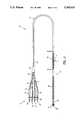
- FIG. 1is a plan view of the optimized field defibrillation catheter of the present invention:
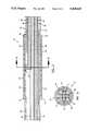
- FIG. 2is a crossectional view of the catheter of FIG, 1, taken along line 2--2 thereof;
- FIG. 3is a crossectional view of the catheter of FIG. 2, taken along line 3--3 thereof;
- FIG. 4is a plan view of another embodiment of the optimized field defibrillation catheter of this invention.
- FIG. 5is a crossectional view of the catheter of FIG. 4, taken along line 5--5 thereof;
- FIG. 6is a crossectional view of the catheter of FIG. 5, taken along line 6--6 thereof;
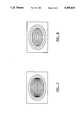
- FIG. 7is a two-dimensional simulation of the voltage distribution around the electrode of a prior art defibrillation catheter.
- FIG.is a two dimensional simulation of the voltage distribution around the electrode of the optimized field defibrillation catheter of the present invention.
- ICDimplantable cardioverter-defibrillator
- the implantable defibrillatoris linked to electrodes which conduct current from the device to the human heart. These electrodes have typically been two or more patches stitched or otherwise secured to the heart. They are referred to as epicardial patch electrodes. Alternatively, to avoid the surgery required for the epicardial patches, large surface area electrode coils are sometimes threaded into the heart chambers through the patient's veins. These are known as transvenous electrodes.
- One coil-type electrodeis typically disposed just above the heart in the right atrium (RA) location and the other is disposed in the right ventricular apex (RVA). Unfortunately, transvenous electrodes are often unable to direct sufficient current through enough of the heart muscle.
- a small patchis additionally inserted just under the skin, on the patient's lower left side. This requires additional, but minimal surgery.
- This subcutaneous patchis not in direct contact with the heart but allows a current vector starting at a transvenous electrode and going through heart muscle. Thus, the subcutaneous patch assists in directing current thru the heart muscle and hence in defibrillating the heart.
- the functional conductive part of the transvenous defibrillation catheter electrodeis either a ribbon or coil of wire wrapped around a flexible polymer. This is usually referred to as the "defibrillation coil” regardless of construction.
- a typical coil diameteris 2-3 mm., and typical lengths of the coil electrode are 4 to 12 cm.
- the typical catheter lead conductorenters from the left and is attached to the electrode coil at both ends. This provides for a low resistance connection between the lead conductor and the electrode coil.
- Unfortunately, in this configuration the current distribution around the electrode coilis very uneven.
- a ring shaped area in the middle of the coilfeeds current to a disk-shaped volume of blood.
- each end point of the coilmust feed current to a larger hemispherical area of blood. This results in much more current flowing from the ends than from the middle of the coil.
- the “sharper" the surface (smaller radii) of the conductorthe greater the electrical field that is generated.
- FIG. 7shows a two-dimensional simulation of the voltage distribution around a typical prior art defibrillation catheter electrode wherein the current conduction lead is connected at both ends of the catheter electrode.
- the crowding of the field lines around the electrode endsshould be noted. These lines are isopotential lines and each line represents a 20 volt increase over its outer neighbor.
- the distribution shownis for qualitative purposes only, as the field concentrations will be different in three dimensions.
- the defibrillation catheter 10 of the present inventionis a thin, elongated tubular structure having a connection end 11 for mating with an implantable cardiac defibrillator apparatus (not shown), a cable 12 extending a predetermined length from the connection end 11, and an electrode end 13 disposed at the other end of the cable 12.
- the electrode end 13has a predetermined length and terminates in an anchor structure 14 which lodges in cardiac tissue on the interior of the patient's heart.
- connection end 11is communicatively connectable to the ICD and is shown to have four (4) terminal leads, 15, 16, 17 and 18.
- Each terminal lead 15-18comprises a lead plug end 19 having plug end tip 20, an insulated lead conductor 21, and a strain relief sheath 22. All of the terminal leads 15-18 run into a lead collector 23 which interfaces the catheter cable 12.
- the electrode end 13is shown to have four (4) electrodes 25, 26, 27 and 28, spaced at predetermined intervals and corresponding to the leads 15-18.
- electrode 25is a proximal defibrillation electrode
- electrode 26is a distal defibrillation electrode
- electrode 27is a proximal pace/sense electrode
- electrode 28is a distal pace/sense electrode.
- the function of electrodes 25-28may be varied, depending upon the particular ICD apparatus utilized and the medical application specified, by altering the connection scheme of leads 15-18. When required, one or more of the electrodes 25-28 may be rendered inoperative.
- the catheter 10can be reconfigured, consistent with the teachings of this invention, to have two (2) or three (3) electrodes to suit particular medical applications.
- the spacing of the defibrillation electrodes 25 and 26is a function of the structure and dimensions of the human heart and the prescribed location of the electrodes 25 and 26 therein, typically at the connection of the superior vena cava to the heart and at the left ventricle. Additionally, the length and outer surface area of the electrodes 25 and 26 is selected to maximize current distribution to the patient's heart tissue.
- the cable 12communicatively connects the leads 15-18 of the connection end 11 with the electrodes 25-28 of the electrode end 13.
- the multi-lumen cable 12is shown to comprise four (4) lead conductors 34, 36, 38 and 40.
- Each lead conductor 34, 36, 38 and 40has an inner insulator 35, 37, 39 and 41, respectively.
- an outer insulator 24surrounds the entire group of leads.
- the leads 34, 36, 38 and 40are shown to be constructed of a solid conductive, metallic wire. However, they may be constructed of a plurality of twisted strands of wire or a single coiled wire, as is known in the art.
- the insulators 24, 35, 37, 39 and 41are preferably constructed of a non-conductive polymeric substance, such as polyurethane, as is known in the art.
- the cylindrically configured defibrillation electrodes 2 and 26preferably comprise a continuous strand of a conductive metallic material 44 which is coiled between a pair of electrode end rings 42 and 43 and wrapped around a base structure. Electrodes having a solid or other configuration may also be utilized to practice the teachings of this invention. Preferred electrode conductive materials include stainless steel, titanium, platinum and various alloys thereof. The over all axial length of the electrodes 25 and 26 are preferably between 4-6 cm. The diameter of the cylindrical electrodes 15 and 16 are preferably between 2-3 mm. Additionally, the electrode coil 44 has a predetermined crossectional width and thickness. Each coil segment is separated from adjacent coil segments a predetermined distance via the above described wrapping.
- lead conductor 34is connected to the conductive coil 44 of electrode 25, preferably at the mid-point of the axial length of the cylindrical electrode 25.
- the connection interface 45 of the coil 44 and lead 34is shown to be made via a weld, although other connection methods and means such as a mechanical connection or connection interface structure may also be used.
- Defibrillation electrode 26is connected to lead 36, also at the mid-point of its length.
- the mid-point connection (A)is the most preferred point of connection between the lead and the electrode 25 because it is equidistant from each electrode end.
- preferred and acceptable regions of connection on the electrode 25are shown in the middle 10 percent (B) and 50 percent (C) sections, respectively, of the axial length of the electrode.
- the spacing from the lead connection point 45 to the electrode ends 42 and 43allows for a voltage drop from the center of the electrode 25 to the ends, which minimizes extreme fields which may otherwise develop at the ends.
- the coil 44 material and coil crossectional dimensionsare preferably selected to yield a predetermined internal resistance for the coil 44, and to thus further control the field distribution around the electrode 25.
- An optimum resistance of approximately 10 ohms from the middle of the electrode 25 to an endresults in improved field distribution so as to allow passage of a large defibrillation current without cardiac tissue damage which would otherwise occur.
- FIG. 8is a two-dimensional simulation of the expected voltage distribution around a defibrillation catheter 10 electrode 25 in accordance with the present invention.
- Each isopotential linerepresents a 20 volt increase over its outer neighbor.
- Currentis fed to the defibrillation electrode 25 at the center of the coil 44 as shown in FIG. 2, for example.
- the coil 44 resistanceallows the voltage along the electrode 25 to taper off as it approaches the ends 42 and 43. In this simulation, the voltage is allowed to decay to 50 percent of the center voltage by the time it reaches the electrode 25 ends.
- the catheter 51basically comprises an ICD connection end 52, an insulated cable 53 and an electrode end 54.
- a pair of leads 55 and 56extend from the connection end 52, through the cable 53 to a pair of cylindrically configured electrodes 57 and 58 disposed at the electrode end 54.
- the overall exterior dimensions of this particular catheter 51 embodimentare dependent upon several factors which are known. And although only two (2) electrodes 57 and 58 are shown, the catheter 51 can be reconfigured, consistent with the teachings of this invention, with three (3) or more electrodes to meet specific medical applications.
- the coaxial cable 53is shown comprising an outer insulator 64, a first conductive lead 59, an inner insulator 61, and a second conductive lead 60. These elements are all arranged in a layered, coaxial configuration.
- the electrodes 57 and 58preferably have a coiled structure, including individual coil segments 62.
- the leads 59 and 60are coupled to electrodes 57 and 58, respectively, at their mid-points.
- a connective interface or junction 63is made between lead 59 and the coil 62.
Landscapes
- Health & Medical Sciences (AREA)
- Heart & Thoracic Surgery (AREA)
- Cardiology (AREA)
- Nuclear Medicine, Radiotherapy & Molecular Imaging (AREA)
- Engineering & Computer Science (AREA)
- Biomedical Technology (AREA)
- Vascular Medicine (AREA)
- Radiology & Medical Imaging (AREA)
- Life Sciences & Earth Sciences (AREA)
- Animal Behavior & Ethology (AREA)
- General Health & Medical Sciences (AREA)
- Public Health (AREA)
- Veterinary Medicine (AREA)
- Electrotherapy Devices (AREA)
Abstract
Description
Claims (16)
Priority Applications (1)
| Application Number | Priority Date | Filing Date | Title |
|---|---|---|---|
| US07/915,063US5265623A (en) | 1992-07-16 | 1992-07-16 | Optimized field defibrillation catheter |
Applications Claiming Priority (1)
| Application Number | Priority Date | Filing Date | Title |
|---|---|---|---|
| US07/915,063US5265623A (en) | 1992-07-16 | 1992-07-16 | Optimized field defibrillation catheter |
Publications (1)
| Publication Number | Publication Date |
|---|---|
| US5265623Atrue US5265623A (en) | 1993-11-30 |
Family
ID=25435151
Family Applications (1)
| Application Number | Title | Priority Date | Filing Date |
|---|---|---|---|
| US07/915,063Expired - LifetimeUS5265623A (en) | 1992-07-16 | 1992-07-16 | Optimized field defibrillation catheter |
Country Status (1)
| Country | Link |
|---|---|
| US (1) | US5265623A (en) |
Cited By (76)
| Publication number | Priority date | Publication date | Assignee | Title |
|---|---|---|---|---|
| US5417713A (en)* | 1993-02-09 | 1995-05-23 | Leonard Bloom | Transesophageal defibrillating system |
| US5439485A (en)* | 1993-09-24 | 1995-08-08 | Ventritex, Inc. | Flexible defibrillation electrode of improved construction |
| US5454839A (en)* | 1992-07-27 | 1995-10-03 | Angeion Corporation | Low profile defibrillation catheter |
| WO1996006655A1 (en)* | 1994-08-29 | 1996-03-07 | Angeion Corporation | Low profile defibrillation catheter |
| US5545193A (en)* | 1993-10-15 | 1996-08-13 | Ep Technologies, Inc. | Helically wound radio-frequency emitting electrodes for creating lesions in body tissue |
| US5549661A (en)* | 1993-10-15 | 1996-08-27 | Ep Technologies, Inc. | Systems and methods for creating complex lesion patterns in body tissue |
| US5575810A (en)* | 1993-10-15 | 1996-11-19 | Ep Technologies, Inc. | Composite structures and methods for ablating tissue to form complex lesion patterns in the treatment of cardiac conditions and the like |
| US5582609A (en)* | 1993-10-14 | 1996-12-10 | Ep Technologies, Inc. | Systems and methods for forming large lesions in body tissue using curvilinear electrode elements |
| EP0769308A1 (en)* | 1995-10-17 | 1997-04-23 | Pacesetter, Inc. | Implantable pacemaker lead |
| US5649974A (en)* | 1992-07-27 | 1997-07-22 | Angeion Corporation | Low profile defibrillation catheter |
| WO1997020595A3 (en)* | 1995-12-04 | 1997-08-28 | Dagmar Hartung | Device for stimulating excitable tissue |
| US5676784A (en)* | 1995-03-15 | 1997-10-14 | Abbott Laboratories | Method of fabricating a heater coil for a catheter used to monitor cardiac output |
| US5676694A (en)* | 1996-06-07 | 1997-10-14 | Medtronic, Inc. | Medical electrical lead |
| US5713944A (en)* | 1996-02-13 | 1998-02-03 | Angeion Corporation | Cardioversion-defibrillation catheter lead having selectively exposable outer conductors |
| US5728149A (en)* | 1995-12-20 | 1998-03-17 | Medtronic, Inc. | Integral spiral band electrode for transvenous defibrillation leads |
| US5849031A (en)* | 1997-12-16 | 1998-12-15 | Medtronic, Inc. | Method and apparatus for termination of tachyarrhythmias |
| US6001093A (en)* | 1993-10-15 | 1999-12-14 | Ep Technologies, Inc. | Systems and methods for creating long, thin lesions in body tissue |
| US6106522A (en)* | 1993-10-14 | 2000-08-22 | Ep Technologies, Inc. | Systems and methods for forming elongated lesion patterns in body tissue using straight or curvilinear electrode elements |
| WO2000048668A1 (en)* | 1999-02-18 | 2000-08-24 | Intermedics Inc. | Endocardial defibrillation lead with strain-relief coil connection |
| US6129724A (en)* | 1993-10-14 | 2000-10-10 | Ep Technologies, Inc. | Systems and methods for forming elongated lesion patterns in body tissue using straight or curvilinear electrode elements |
| US6146379A (en)* | 1993-10-15 | 2000-11-14 | Ep Technologies, Inc. | Systems and methods for creating curvilinear lesions in body tissue |
| US6219582B1 (en) | 1998-12-30 | 2001-04-17 | Daig Corporation | Temporary atrial cardioversion catheter |
| WO2001036046A1 (en) | 1999-11-18 | 2001-05-25 | Intermedics, Inc. | Dual-chambered pacemaker and defibrillator |
| US6287306B1 (en) | 1998-06-22 | 2001-09-11 | Daig Corporation | Even temperature linear lesion ablation catheter |
| US20010025192A1 (en)* | 1999-04-29 | 2001-09-27 | Medtronic, Inc. | Single and multi-polar implantable lead for sacral nerve electrical stimulation |
| US6442425B1 (en) | 1997-08-01 | 2002-08-27 | Intermedics, Inc. | Cardiac stimulator and defibrillator |
| US6484057B2 (en)* | 2000-12-21 | 2002-11-19 | Uab Research Foundation | Pacing methods and devices for treating cardiac arrhythmias and fibrillation |
| US6501992B1 (en) | 2000-10-17 | 2002-12-31 | Medtronic, Inc. | Radiopaque marking of lead electrode zone in a continuous conductor construction |
| US20030092303A1 (en)* | 2001-11-09 | 2003-05-15 | Osypka Thomas P. | Multifilar conductor for cardiac leads |
| US6615695B1 (en) | 2000-06-27 | 2003-09-09 | Medtronic, Inc. | Alternative fabrication method for spiral electrodes |
| US20030199953A1 (en)* | 2002-04-22 | 2003-10-23 | Stolz Brian T. | Implantable lead with coplanar contact coupling |
| US20030199950A1 (en)* | 2002-04-22 | 2003-10-23 | Brian Stolz | Implantable lead with isolated contact coupling |
| US20040249430A1 (en)* | 2003-06-03 | 2004-12-09 | Medtronic, Inc. | Implantable medical electrical lead |
| US20050143412A1 (en)* | 1997-08-26 | 2005-06-30 | Puskas John D. | Methods of indirectly stimulating the vagus nerve with an electrical field |
| US20050267407A1 (en)* | 2002-02-01 | 2005-12-01 | Vascular Designs, Inc. | Multi-function catheter and use thereof |
| US7048734B1 (en) | 1993-10-15 | 2006-05-23 | Ep Technologies, Inc. | Systems and methods for electronically altering the energy emitting characteristics of an electrode array to create different lesion patterns in body tissue |
| US20060122681A1 (en)* | 2004-12-06 | 2006-06-08 | Kroll Mark W | Automatic capture pacing lead |
| US7184828B2 (en) | 2000-09-26 | 2007-02-27 | Medtronic, Inc. | Method and system for spinal cord stimulation prior to and during a medical procedure |
| US7184829B2 (en) | 1996-04-30 | 2007-02-27 | Medtronic, Inc. | Method and system for nerve stimulation prior to and during a medical procedure |
| US7225019B2 (en) | 1996-04-30 | 2007-05-29 | Medtronic, Inc. | Method and system for nerve stimulation and cardiac sensing prior to and during a medical procedure |
| US7239915B2 (en) | 2003-12-16 | 2007-07-03 | Medtronic, Inc. | Hemodynamic optimization system for biventricular implants |
| US7269457B2 (en) | 1996-04-30 | 2007-09-11 | Medtronic, Inc. | Method and system for vagal nerve stimulation with multi-site cardiac pacing |
| US20070276442A1 (en)* | 2005-05-19 | 2007-11-29 | Cvrx, Inc. | Implantable electrode assembly having reverse electrode configuration |
| US7412289B2 (en)* | 1998-11-05 | 2008-08-12 | Impulse Dynamics (Israel) Ltd. | Multi-electrode lead |
| US20080208118A1 (en)* | 2002-02-01 | 2008-08-28 | Vascular Designs, Inc. | Multi-function catheter and use thereof |
| US7587239B1 (en) | 2003-09-24 | 2009-09-08 | Pacesetter, Inc. | Cardiac pacemaker system, lead and method for rejecting far-field signals |
| US20090240159A1 (en)* | 2001-12-05 | 2009-09-24 | Yinghong Yu | Sensing cardiac contractile function |
| US20100004708A1 (en)* | 1996-04-30 | 2010-01-07 | Medtronic, Inc. | Method and system for nerve stimulation and cardiac sensing prior to and during a medical procedure |
| US20100114021A1 (en)* | 2002-02-01 | 2010-05-06 | Vascular Designs, Inc. | Multi-function catheter and use thereof |
| US20100217365A1 (en)* | 2009-02-23 | 2010-08-26 | Medtronic, Inc. | Medical lead having coaxial connector |
| US7840278B1 (en) | 1999-06-25 | 2010-11-23 | Puskas John D | Devices and methods for vagus nerve stimulation |
| US20120130461A1 (en)* | 2009-04-30 | 2012-05-24 | Medtronic, Inc. | Radiopaque markers for implantable medical leads, devices, and systems |
| US8406868B2 (en) | 2010-04-29 | 2013-03-26 | Medtronic, Inc. | Therapy using perturbation and effect of physiological systems |
| US8412320B2 (en)* | 2000-09-18 | 2013-04-02 | Cameron Health, Inc. | Nontransvenous and nonepicardial methods of cardiac treatment and stimulus |
| US8620425B2 (en) | 2010-04-29 | 2013-12-31 | Medtronic, Inc. | Nerve signal differentiation in cardiac therapy |
| US8639327B2 (en) | 2010-04-29 | 2014-01-28 | Medtronic, Inc. | Nerve signal differentiation in cardiac therapy |
| US8706223B2 (en) | 2011-01-19 | 2014-04-22 | Medtronic, Inc. | Preventative vagal stimulation |
| US8706217B2 (en) | 2000-09-18 | 2014-04-22 | Cameron Health | Cardioverter-defibrillator having a focused shocking area and orientation thereof |
| US8718763B2 (en) | 2011-01-19 | 2014-05-06 | Medtronic, Inc. | Vagal stimulation |
| US8718760B2 (en) | 2000-09-18 | 2014-05-06 | Cameron Health Inc. | Subcutaneous implantable cardioverter-defibrillator placement methods |
| US8725259B2 (en) | 2011-01-19 | 2014-05-13 | Medtronic, Inc. | Vagal stimulation |
| US8781583B2 (en) | 2011-01-19 | 2014-07-15 | Medtronic, Inc. | Vagal stimulation |
| US8781582B2 (en) | 2011-01-19 | 2014-07-15 | Medtronic, Inc. | Vagal stimulation |
| US8831720B2 (en) | 2000-09-18 | 2014-09-09 | Cameron Health, Inc. | Method of implanting and using a subcutaneous defibrillator |
| US9138589B2 (en) | 2001-11-21 | 2015-09-22 | Cameron Health, Inc. | Apparatus and method for identifying atrial arrhythmia by far-field sensing |
| US9144683B2 (en) | 2000-09-18 | 2015-09-29 | Cameron Health, Inc. | Post-shock treatment in a subcutaneous device |
| US9259572B2 (en) | 2007-04-25 | 2016-02-16 | Medtronic, Inc. | Lead or lead extension having a conductive body and conductive body contact |
| US9302101B2 (en) | 2004-03-30 | 2016-04-05 | Medtronic, Inc. | MRI-safe implantable lead |
| US9463317B2 (en) | 2012-04-19 | 2016-10-11 | Medtronic, Inc. | Paired medical lead bodies with braided conductive shields having different physical parameter values |
| US9731119B2 (en) | 2008-03-12 | 2017-08-15 | Medtronic, Inc. | System and method for implantable medical device lead shielding |
| JP2017153633A (en)* | 2016-02-29 | 2017-09-07 | 日本ライフライン株式会社 | Intracardiac defibrillation catheter |
| US9993638B2 (en) | 2013-12-14 | 2018-06-12 | Medtronic, Inc. | Devices, systems and methods to reduce coupling of a shield and a conductor within an implantable medical lead |
| US10155111B2 (en) | 2014-07-24 | 2018-12-18 | Medtronic, Inc. | Methods of shielding implantable medical leads and implantable medical lead extensions |
| US10279171B2 (en) | 2014-07-23 | 2019-05-07 | Medtronic, Inc. | Methods of shielding implantable medical leads and implantable medical lead extensions |
| JP2019122862A (en)* | 2019-05-09 | 2019-07-25 | 日本ライフライン株式会社 | Intracardiac defibrillation catheter |
| US10398893B2 (en) | 2007-02-14 | 2019-09-03 | Medtronic, Inc. | Discontinuous conductive filler polymer-matrix composites for electromagnetic shielding |
Citations (4)
| Publication number | Priority date | Publication date | Assignee | Title |
|---|---|---|---|---|
| US3769984A (en)* | 1971-03-11 | 1973-11-06 | Sherwood Medical Ind Inc | Pacing catheter with frictional fit lead attachment |
| US4603705A (en)* | 1984-05-04 | 1986-08-05 | Mieczyslaw Mirowski | Intravascular multiple electrode unitary catheter |
| US4630611A (en)* | 1981-02-02 | 1986-12-23 | Medtronic, Inc. | Orthogonally-sensing lead |
| US5044375A (en)* | 1989-12-08 | 1991-09-03 | Cardiac Pacemakers, Inc. | Unitary intravascular defibrillating catheter with separate bipolar sensing |
- 1992
- 1992-07-16USUS07/915,063patent/US5265623A/ennot_activeExpired - Lifetime
Patent Citations (4)
| Publication number | Priority date | Publication date | Assignee | Title |
|---|---|---|---|---|
| US3769984A (en)* | 1971-03-11 | 1973-11-06 | Sherwood Medical Ind Inc | Pacing catheter with frictional fit lead attachment |
| US4630611A (en)* | 1981-02-02 | 1986-12-23 | Medtronic, Inc. | Orthogonally-sensing lead |
| US4603705A (en)* | 1984-05-04 | 1986-08-05 | Mieczyslaw Mirowski | Intravascular multiple electrode unitary catheter |
| US5044375A (en)* | 1989-12-08 | 1991-09-03 | Cardiac Pacemakers, Inc. | Unitary intravascular defibrillating catheter with separate bipolar sensing |
Cited By (146)
| Publication number | Priority date | Publication date | Assignee | Title |
|---|---|---|---|---|
| US5454839A (en)* | 1992-07-27 | 1995-10-03 | Angeion Corporation | Low profile defibrillation catheter |
| US5649974A (en)* | 1992-07-27 | 1997-07-22 | Angeion Corporation | Low profile defibrillation catheter |
| US5417713A (en)* | 1993-02-09 | 1995-05-23 | Leonard Bloom | Transesophageal defibrillating system |
| US5439485A (en)* | 1993-09-24 | 1995-08-08 | Ventritex, Inc. | Flexible defibrillation electrode of improved construction |
| US5542173A (en)* | 1993-09-24 | 1996-08-06 | Ventritex, Inc. | Method of making flexible defibrillation electrode |
| US6171306B1 (en) | 1993-10-14 | 2001-01-09 | Ep Technologies, Inc. | Systems and methods for forming large lesions in body tissue using curvilinear electrode elements |
| US6129724A (en)* | 1993-10-14 | 2000-10-10 | Ep Technologies, Inc. | Systems and methods for forming elongated lesion patterns in body tissue using straight or curvilinear electrode elements |
| US6106522A (en)* | 1993-10-14 | 2000-08-22 | Ep Technologies, Inc. | Systems and methods for forming elongated lesion patterns in body tissue using straight or curvilinear electrode elements |
| US6471699B1 (en) | 1993-10-14 | 2002-10-29 | Ep Technologies, Inc. | Systems and methods for forming elongated lesion patterns in body tissue using straight or curvilinear electrode elements |
| US5582609A (en)* | 1993-10-14 | 1996-12-10 | Ep Technologies, Inc. | Systems and methods for forming large lesions in body tissue using curvilinear electrode elements |
| US6514246B1 (en) | 1993-10-14 | 2003-02-04 | Ep Technologies, Inc. | Systems and methods for forming large lesions in body tissue using curvilinear electrode elements |
| US5549661A (en)* | 1993-10-15 | 1996-08-27 | Ep Technologies, Inc. | Systems and methods for creating complex lesion patterns in body tissue |
| US5575810A (en)* | 1993-10-15 | 1996-11-19 | Ep Technologies, Inc. | Composite structures and methods for ablating tissue to form complex lesion patterns in the treatment of cardiac conditions and the like |
| US7837684B2 (en) | 1993-10-15 | 2010-11-23 | Ep Technologies, Inc. | Composite structures and methods for ablating tissue to form complex lesion patterns in the treatment of cardiac conditions and the like |
| US20080161802A1 (en)* | 1993-10-15 | 2008-07-03 | Swanson David K | Composite Structures and Methods for Ablating Tissue to Form Complex Lesion Patterns in the Treatment of Cardiac Conditions and the Like |
| US7335196B2 (en) | 1993-10-15 | 2008-02-26 | Ep Technologies, Inc. | Systems and methods for creating long, thin lesions in body tissue |
| US7048734B1 (en) | 1993-10-15 | 2006-05-23 | Ep Technologies, Inc. | Systems and methods for electronically altering the energy emitting characteristics of an electrode array to create different lesion patterns in body tissue |
| US7413568B2 (en) | 1993-10-15 | 2008-08-19 | Ep Technologies, Inc. | Composite structures and methods for ablating tissue to form complex lesion patterns in the treatment of cardiac conditions and the like |
| US7115122B1 (en) | 1993-10-15 | 2006-10-03 | Ep Technologies, Inc. | Composite structures and methods for ablating tissue to form complex lesion patterns in the treatment of cardiac conditions and the like |
| US6001093A (en)* | 1993-10-15 | 1999-12-14 | Ep Technologies, Inc. | Systems and methods for creating long, thin lesions in body tissue |
| US6241754B1 (en) | 1993-10-15 | 2001-06-05 | Ep Technologies, Inc. | Composite structures and methods for ablating tissue to form complex lesion patterns in the treatment of cardiac conditions and the like |
| US6447506B1 (en) | 1993-10-15 | 2002-09-10 | Ep Technologies, Inc. | Systems and methods for creating long, thin lesions in body tissue |
| US5545193A (en)* | 1993-10-15 | 1996-08-13 | Ep Technologies, Inc. | Helically wound radio-frequency emitting electrodes for creating lesions in body tissue |
| US6146379A (en)* | 1993-10-15 | 2000-11-14 | Ep Technologies, Inc. | Systems and methods for creating curvilinear lesions in body tissue |
| US20010029366A1 (en)* | 1993-10-15 | 2001-10-11 | Swanson David K. | Composite structures and methods for ablating tissue to form complex lesion patterns in the treatment of cardiac conditions and the like |
| WO1996006655A1 (en)* | 1994-08-29 | 1996-03-07 | Angeion Corporation | Low profile defibrillation catheter |
| US5676784A (en)* | 1995-03-15 | 1997-10-14 | Abbott Laboratories | Method of fabricating a heater coil for a catheter used to monitor cardiac output |
| US5662697A (en)* | 1995-10-17 | 1997-09-02 | Pacesetter, Inc. | Transvenous internal cardiac defibrillation apparatus having lead and electrode providing even distribution of electrical charge |
| EP0769308A1 (en)* | 1995-10-17 | 1997-04-23 | Pacesetter, Inc. | Implantable pacemaker lead |
| WO1997020595A3 (en)* | 1995-12-04 | 1997-08-28 | Dagmar Hartung | Device for stimulating excitable tissue |
| US5728149A (en)* | 1995-12-20 | 1998-03-17 | Medtronic, Inc. | Integral spiral band electrode for transvenous defibrillation leads |
| US5713944A (en)* | 1996-02-13 | 1998-02-03 | Angeion Corporation | Cardioversion-defibrillation catheter lead having selectively exposable outer conductors |
| US8036741B2 (en) | 1996-04-30 | 2011-10-11 | Medtronic, Inc. | Method and system for nerve stimulation and cardiac sensing prior to and during a medical procedure |
| US7269457B2 (en) | 1996-04-30 | 2007-09-11 | Medtronic, Inc. | Method and system for vagal nerve stimulation with multi-site cardiac pacing |
| US7184829B2 (en) | 1996-04-30 | 2007-02-27 | Medtronic, Inc. | Method and system for nerve stimulation prior to and during a medical procedure |
| US7225019B2 (en) | 1996-04-30 | 2007-05-29 | Medtronic, Inc. | Method and system for nerve stimulation and cardiac sensing prior to and during a medical procedure |
| US20100004708A1 (en)* | 1996-04-30 | 2010-01-07 | Medtronic, Inc. | Method and system for nerve stimulation and cardiac sensing prior to and during a medical procedure |
| US5676694A (en)* | 1996-06-07 | 1997-10-14 | Medtronic, Inc. | Medical electrical lead |
| US6327499B1 (en)* | 1997-08-01 | 2001-12-04 | Eckhard Alt | Cardiac stimulator and defibrillator |
| US6442425B1 (en) | 1997-08-01 | 2002-08-27 | Intermedics, Inc. | Cardiac stimulator and defibrillator |
| US20050143412A1 (en)* | 1997-08-26 | 2005-06-30 | Puskas John D. | Methods of indirectly stimulating the vagus nerve with an electrical field |
| US7340299B2 (en) | 1997-08-26 | 2008-03-04 | Puskas John D | Methods of indirectly stimulating the vagus nerve to achieve controlled asystole |
| US7142910B2 (en) | 1997-08-26 | 2006-11-28 | Emory University | Methods of indirectly stimulating the vagus nerve with an electrical field |
| US7310552B2 (en) | 1997-08-26 | 2007-12-18 | Puskas John D | Apparatus for indirectly stimulating the vagus nerve with an electrical field |
| US5849031A (en)* | 1997-12-16 | 1998-12-15 | Medtronic, Inc. | Method and apparatus for termination of tachyarrhythmias |
| WO1999030771A1 (en) | 1997-12-16 | 1999-06-24 | Medtronic, Inc. | Method and apparatus for termination of tachyarrhythmias |
| US20040039382A1 (en)* | 1998-06-22 | 2004-02-26 | Daig Corporation | Even temperature linear lesion ablation catheter |
| US6780181B2 (en) | 1998-06-22 | 2004-08-24 | St. Jude Medical, Daig Division, Inc. | Even temperature linear lesion ablation catheter |
| US6287306B1 (en) | 1998-06-22 | 2001-09-11 | Daig Corporation | Even temperature linear lesion ablation catheter |
| US7412289B2 (en)* | 1998-11-05 | 2008-08-12 | Impulse Dynamics (Israel) Ltd. | Multi-electrode lead |
| US6438426B2 (en) | 1998-12-30 | 2002-08-20 | Daig Corporation | Temporary atrial cardioversion catheter |
| US6219582B1 (en) | 1998-12-30 | 2001-04-17 | Daig Corporation | Temporary atrial cardioversion catheter |
| US6259954B1 (en) | 1999-02-18 | 2001-07-10 | Intermedics Inc. | Endocardial difibrillation lead with strain-relief coil connection |
| WO2000048668A1 (en)* | 1999-02-18 | 2000-08-24 | Intermedics Inc. | Endocardial defibrillation lead with strain-relief coil connection |
| US20080188917A1 (en)* | 1999-04-29 | 2008-08-07 | Medtronic, Inc. | Single and multipolar implantable lead for sacral nerve electrical stimulation |
| US20010025192A1 (en)* | 1999-04-29 | 2001-09-27 | Medtronic, Inc. | Single and multi-polar implantable lead for sacral nerve electrical stimulation |
| US20040093053A1 (en)* | 1999-04-29 | 2004-05-13 | Medtronic, Inc. | Single and multi-polar implantable lead for sacral nerve electrical stimulation |
| US7840278B1 (en) | 1999-06-25 | 2010-11-23 | Puskas John D | Devices and methods for vagus nerve stimulation |
| WO2001036046A1 (en) | 1999-11-18 | 2001-05-25 | Intermedics, Inc. | Dual-chambered pacemaker and defibrillator |
| US6615695B1 (en) | 2000-06-27 | 2003-09-09 | Medtronic, Inc. | Alternative fabrication method for spiral electrodes |
| US8706217B2 (en) | 2000-09-18 | 2014-04-22 | Cameron Health | Cardioverter-defibrillator having a focused shocking area and orientation thereof |
| US8838234B2 (en)* | 2000-09-18 | 2014-09-16 | Cameron Health, Inc. | Methods for implanting a subcutaneous defibrillator |
| US9144683B2 (en) | 2000-09-18 | 2015-09-29 | Cameron Health, Inc. | Post-shock treatment in a subcutaneous device |
| US8412320B2 (en)* | 2000-09-18 | 2013-04-02 | Cameron Health, Inc. | Nontransvenous and nonepicardial methods of cardiac treatment and stimulus |
| US8831720B2 (en) | 2000-09-18 | 2014-09-09 | Cameron Health, Inc. | Method of implanting and using a subcutaneous defibrillator |
| US8718760B2 (en) | 2000-09-18 | 2014-05-06 | Cameron Health Inc. | Subcutaneous implantable cardioverter-defibrillator placement methods |
| US20070208381A1 (en)* | 2000-09-26 | 2007-09-06 | Medtronic, Inc. | Method and system for spinal cord stimulation prior to and during a medical procedure |
| US7184828B2 (en) | 2000-09-26 | 2007-02-27 | Medtronic, Inc. | Method and system for spinal cord stimulation prior to and during a medical procedure |
| US20110160573A1 (en)* | 2000-10-17 | 2011-06-30 | Medtronic Inc. | Radiopaque Marking of Lead Electrode Zone in a Continuous Conductor Construction |
| US7277762B2 (en) | 2000-10-17 | 2007-10-02 | Belden Elisabeth L | Radiopague marking of lead electrode zone in a continuous conductor construction |
| US7925358B2 (en) | 2000-10-17 | 2011-04-12 | Medtronic, Inc. | Radiopaque marking of lead electrode zone in a continuous conductor construction |
| US20070293924A1 (en)* | 2000-10-17 | 2007-12-20 | Belden Elisabeth L | Radiopaque marking of lead electrode zone in a continuous conductor construction |
| US6501992B1 (en) | 2000-10-17 | 2002-12-31 | Medtronic, Inc. | Radiopaque marking of lead electrode zone in a continuous conductor construction |
| US6484057B2 (en)* | 2000-12-21 | 2002-11-19 | Uab Research Foundation | Pacing methods and devices for treating cardiac arrhythmias and fibrillation |
| US6978185B2 (en) | 2001-11-09 | 2005-12-20 | Oscor Inc. | Multifilar conductor for cardiac leads |
| US20030092303A1 (en)* | 2001-11-09 | 2003-05-15 | Osypka Thomas P. | Multifilar conductor for cardiac leads |
| US9993653B2 (en) | 2001-11-21 | 2018-06-12 | Cameron Health, Inc. | Apparatus and method for identifying atrial arrhythmia by far-field sensing |
| US9138589B2 (en) | 2001-11-21 | 2015-09-22 | Cameron Health, Inc. | Apparatus and method for identifying atrial arrhythmia by far-field sensing |
| US9522283B2 (en) | 2001-11-21 | 2016-12-20 | Cameron Health Inc. | Apparatus and method for identifying atrial arrhythmia by far-field sensing |
| US20090240159A1 (en)* | 2001-12-05 | 2009-09-24 | Yinghong Yu | Sensing cardiac contractile function |
| US20090182227A1 (en)* | 2002-02-01 | 2009-07-16 | Vascular Designs, Inc. | Multi-function catheter and use thereof |
| US8062251B2 (en) | 2002-02-01 | 2011-11-22 | Vascular Designs, Inc. | Multi-function catheter and use thereof |
| US20080208118A1 (en)* | 2002-02-01 | 2008-08-28 | Vascular Designs, Inc. | Multi-function catheter and use thereof |
| US20100114021A1 (en)* | 2002-02-01 | 2010-05-06 | Vascular Designs, Inc. | Multi-function catheter and use thereof |
| US20050267407A1 (en)* | 2002-02-01 | 2005-12-01 | Vascular Designs, Inc. | Multi-function catheter and use thereof |
| US8251948B2 (en) | 2002-02-01 | 2012-08-28 | Vascular Designs, Inc. | Multi-function catheter and use thereof |
| US20030199950A1 (en)* | 2002-04-22 | 2003-10-23 | Brian Stolz | Implantable lead with isolated contact coupling |
| US20030199953A1 (en)* | 2002-04-22 | 2003-10-23 | Stolz Brian T. | Implantable lead with coplanar contact coupling |
| US7953496B2 (en) | 2002-04-22 | 2011-05-31 | Medtronic, Inc. | Implantable lead with isolated contact coupling |
| US7856707B2 (en) | 2002-04-22 | 2010-12-28 | Medtronic, Inc. | Method for performing a coplanar connection between a conductor and a contact on an implantable lead |
| US8000802B2 (en) | 2002-04-22 | 2011-08-16 | Medtronic, Inc. | Implantable lead with coplanar contact coupling |
| US20110202118A1 (en)* | 2002-04-22 | 2011-08-18 | Medtronic, Inc. | Implantable lead with isolated contact coupling |
| US7184840B2 (en)* | 2002-04-22 | 2007-02-27 | Medtronic, Inc. | Implantable lead with isolated contact coupling |
| US20040019372A1 (en)* | 2002-04-22 | 2004-01-29 | Cole Mary Lee | Implantable lead with coplanar contact coupling |
| US8504168B2 (en) | 2002-04-22 | 2013-08-06 | Medtronic, Inc. | Implantable lead with coplanar contact coupling |
| US20040024440A1 (en)* | 2002-04-22 | 2004-02-05 | Cole Mary Lee | Implantable lead with isolated contact coupling |
| US8306631B2 (en) | 2002-04-22 | 2012-11-06 | Medtronic, Inc. | Implantable lead with coplanar contact coupling |
| US8386055B2 (en) | 2002-04-22 | 2013-02-26 | Medtronic, Inc. | Implantable lead with isolated contact coupling |
| US20110118814A1 (en)* | 2002-04-22 | 2011-05-19 | Medtronic, Inc. | Implantable lead with coplanar contact coupling |
| US20040249430A1 (en)* | 2003-06-03 | 2004-12-09 | Medtronic, Inc. | Implantable medical electrical lead |
| US7587239B1 (en) | 2003-09-24 | 2009-09-08 | Pacesetter, Inc. | Cardiac pacemaker system, lead and method for rejecting far-field signals |
| US7239915B2 (en) | 2003-12-16 | 2007-07-03 | Medtronic, Inc. | Hemodynamic optimization system for biventricular implants |
| US9302101B2 (en) | 2004-03-30 | 2016-04-05 | Medtronic, Inc. | MRI-safe implantable lead |
| US20060122681A1 (en)* | 2004-12-06 | 2006-06-08 | Kroll Mark W | Automatic capture pacing lead |
| US20080140167A1 (en)* | 2005-05-19 | 2008-06-12 | Cvrx, Inc. | Implantable electrode assembly having reverse electrode configuration |
| US20070276442A1 (en)* | 2005-05-19 | 2007-11-29 | Cvrx, Inc. | Implantable electrode assembly having reverse electrode configuration |
| US7395119B2 (en) | 2005-05-19 | 2008-07-01 | Cvrx, Inc. | Implantable electrode assembly having reverse electrode configuration |
| US10398893B2 (en) | 2007-02-14 | 2019-09-03 | Medtronic, Inc. | Discontinuous conductive filler polymer-matrix composites for electromagnetic shielding |
| US9259572B2 (en) | 2007-04-25 | 2016-02-16 | Medtronic, Inc. | Lead or lead extension having a conductive body and conductive body contact |
| US9731119B2 (en) | 2008-03-12 | 2017-08-15 | Medtronic, Inc. | System and method for implantable medical device lead shielding |
| US8478424B2 (en)* | 2009-02-23 | 2013-07-02 | Medtronic, Inc. | Medical lead having coaxial connector |
| US20100217365A1 (en)* | 2009-02-23 | 2010-08-26 | Medtronic, Inc. | Medical lead having coaxial connector |
| US9220893B2 (en) | 2009-04-30 | 2015-12-29 | Medtronic, Inc. | Shielded implantable medical lead with reduced torsional stiffness |
| US10086194B2 (en) | 2009-04-30 | 2018-10-02 | Medtronic, Inc. | Termination of a shield within an implantable medical lead |
| US12409320B2 (en) | 2009-04-30 | 2025-09-09 | Medtronic, Inc. | Termination of a shield within an implantable medical lead |
| US11260222B2 (en) | 2009-04-30 | 2022-03-01 | Medtronic, Inc. | Radiopaque markers for implantable medical leads, devices, and systems |
| US20120130461A1 (en)* | 2009-04-30 | 2012-05-24 | Medtronic, Inc. | Radiopaque markers for implantable medical leads, devices, and systems |
| US10035014B2 (en) | 2009-04-30 | 2018-07-31 | Medtronic, Inc. | Steering an implantable medical lead via a rotational coupling to a stylet |
| US9186499B2 (en) | 2009-04-30 | 2015-11-17 | Medtronic, Inc. | Grounding of a shield within an implantable medical lead |
| US9205253B2 (en) | 2009-04-30 | 2015-12-08 | Medtronic, Inc. | Shielding an implantable medical lead |
| US9956402B2 (en)* | 2009-04-30 | 2018-05-01 | Medtronic, Inc. | Radiopaque markers for implantable medical leads, devices, and systems |
| US9216286B2 (en) | 2009-04-30 | 2015-12-22 | Medtronic, Inc. | Shielded implantable medical lead with guarded termination |
| US9629998B2 (en) | 2009-04-30 | 2017-04-25 | Medtronics, Inc. | Establishing continuity between a shield within an implantable medical lead and a shield within an implantable lead extension |
| US9452284B2 (en) | 2009-04-30 | 2016-09-27 | Medtronic, Inc. | Termination of a shield within an implantable medical lead |
| US9272136B2 (en) | 2009-04-30 | 2016-03-01 | Medtronic, Inc. | Grounding of a shield within an implantable medical lead |
| US8406868B2 (en) | 2010-04-29 | 2013-03-26 | Medtronic, Inc. | Therapy using perturbation and effect of physiological systems |
| US8888699B2 (en) | 2010-04-29 | 2014-11-18 | Medtronic, Inc. | Therapy using perturbation and effect of physiological systems |
| US11129988B2 (en) | 2010-04-29 | 2021-09-28 | Medtronic, Inc. | Nerve signal differentiation in cardiac therapy |
| US9468764B2 (en) | 2010-04-29 | 2016-10-18 | Medtronic, Inc. | Nerve signal differentiation in cardiac therapy |
| US8620425B2 (en) | 2010-04-29 | 2013-12-31 | Medtronic, Inc. | Nerve signal differentiation in cardiac therapy |
| US8639327B2 (en) | 2010-04-29 | 2014-01-28 | Medtronic, Inc. | Nerve signal differentiation in cardiac therapy |
| US8423134B2 (en) | 2010-04-29 | 2013-04-16 | Medtronic, Inc. | Therapy using perturbation and effect of physiological systems |
| US10207112B2 (en) | 2010-04-29 | 2019-02-19 | Medtronic, Inc. | Cardiac therapy including vagal stimulation |
| US8718763B2 (en) | 2011-01-19 | 2014-05-06 | Medtronic, Inc. | Vagal stimulation |
| US9211413B2 (en) | 2011-01-19 | 2015-12-15 | Medtronic, Inc. | Preventing use of vagal stimulation parameters |
| US9155893B2 (en) | 2011-01-19 | 2015-10-13 | Medtronic, Inc. | Use of preventative vagal stimulation in treatment of acute myocardial infarction or ischemia |
| US8781582B2 (en) | 2011-01-19 | 2014-07-15 | Medtronic, Inc. | Vagal stimulation |
| US8725259B2 (en) | 2011-01-19 | 2014-05-13 | Medtronic, Inc. | Vagal stimulation |
| US8781583B2 (en) | 2011-01-19 | 2014-07-15 | Medtronic, Inc. | Vagal stimulation |
| US8706223B2 (en) | 2011-01-19 | 2014-04-22 | Medtronic, Inc. | Preventative vagal stimulation |
| US9463317B2 (en) | 2012-04-19 | 2016-10-11 | Medtronic, Inc. | Paired medical lead bodies with braided conductive shields having different physical parameter values |
| US9993638B2 (en) | 2013-12-14 | 2018-06-12 | Medtronic, Inc. | Devices, systems and methods to reduce coupling of a shield and a conductor within an implantable medical lead |
| US10279171B2 (en) | 2014-07-23 | 2019-05-07 | Medtronic, Inc. | Methods of shielding implantable medical leads and implantable medical lead extensions |
| US10155111B2 (en) | 2014-07-24 | 2018-12-18 | Medtronic, Inc. | Methods of shielding implantable medical leads and implantable medical lead extensions |
| JP2017153633A (en)* | 2016-02-29 | 2017-09-07 | 日本ライフライン株式会社 | Intracardiac defibrillation catheter |
| JP2019122862A (en)* | 2019-05-09 | 2019-07-25 | 日本ライフライン株式会社 | Intracardiac defibrillation catheter |
Similar Documents
| Publication | Publication Date | Title |
|---|---|---|
| US5265623A (en) | Optimized field defibrillation catheter | |
| US6978185B2 (en) | Multifilar conductor for cardiac leads | |
| US7158837B2 (en) | Low profile cardiac leads | |
| EP0769308B1 (en) | Implantable pacemaker lead | |
| US6259954B1 (en) | Endocardial difibrillation lead with strain-relief coil connection | |
| US6104961A (en) | Endocardial defibrillation lead with looped cable conductor | |
| US5531782A (en) | Implantable medical electrode with reduced number of conductors | |
| EP2195078B1 (en) | Implantable medical lead with biased electrode | |
| AU630842B2 (en) | Braid electrode leads and catheters and methods for using the same | |
| US4922927A (en) | Transvenous defibrillating and pacing lead | |
| US4481953A (en) | Endocardial lead having helically wound ribbon electrode | |
| US6085117A (en) | Method of defibrillating employing coronary sinus and external patch electrodes | |
| US5269319A (en) | Unitary intravascular defibrillating catheter with bipolar sensing | |
| US5044375A (en) | Unitary intravascular defibrillating catheter with separate bipolar sensing | |
| DE69429420T2 (en) | CORONARY SINE PIPE WHICH ALLOWS THE DETECTION OF AORIAL SIGNALS | |
| US6684109B1 (en) | Endocardial lead | |
| US5649974A (en) | Low profile defibrillation catheter | |
| US20030220676A1 (en) | Electrode arrangements for body implantable pacing and sensing leads | |
| US5713944A (en) | Cardioversion-defibrillation catheter lead having selectively exposable outer conductors | |
| US7831312B2 (en) | Floating adapter for use with auxiliary lead assembly |
Legal Events
| Date | Code | Title | Description |
|---|---|---|---|
| AS | Assignment | Owner name:ANGEION CORPORATION, MINNESOTA Free format text:ASSIGNMENT OF ASSIGNORS INTEREST.;ASSIGNOR:ANGEMED, INC.;REEL/FRAME:006508/0146 Effective date:19930204 | |
| AS | Assignment | Owner name:ANGEION CORPORATION, MINNESOTA Free format text:ASSIGNMENT OF ASSIGNORS INTEREST;ASSIGNORS:KROLL, MARK W.;GILMAN, BYRON L.;REEL/FRAME:006677/0396 Effective date:19930714 | |
| STCF | Information on status: patent grant | Free format text:PATENTED CASE | |
| FEPP | Fee payment procedure | Free format text:PAT HLDR NO LONGER CLAIMS SMALL ENT STAT AS SMALL BUSINESS (ORIGINAL EVENT CODE: LSM2); ENTITY STATUS OF PATENT OWNER: LARGE ENTITY | |
| FPAY | Fee payment | Year of fee payment:4 | |
| AS | Assignment | Owner name:NORWEST BUSINESS CREDIT, INC., MINNESOTA Free format text:SECURITY INTEREST;ASSIGNOR:ANGEION CORPORATION;REEL/FRAME:009693/0097 Effective date:19990118 | |
| AS | Assignment | Owner name:ANGEION CORPORATION, MINNESOTA Free format text:RELEASE OF SECURITY INTEREST;ASSIGNOR:NORWEST BUSINESS CREDIT, INC. (N/K/A WELLS FARGO BUSINESS CREDIT, INC.);REEL/FRAME:010470/0293 Effective date:19991202 | |
| REMI | Maintenance fee reminder mailed | ||
| FPAY | Fee payment | Year of fee payment:8 | |
| SULP | Surcharge for late payment | Year of fee payment:7 | |
| FPAY | Fee payment | Year of fee payment:12 | |
| AS | Assignment | Owner name:ELA MEDICAL, S.A., FRANCE Free format text:ASSIGNMENT OF ASSIGNORS INTEREST;ASSIGNOR:ANGEION CORPORATION;REEL/FRAME:016536/0764 Effective date:20050630 |