US5265357A - Magic 3D effect enhancing frame - Google Patents
Magic 3D effect enhancing frameDownload PDFInfo
- Publication number
- US5265357A US5265357AUS07/823,460US82346092AUS5265357AUS 5265357 AUS5265357 AUS 5265357AUS 82346092 AUS82346092 AUS 82346092AUS 5265357 AUS5265357 AUS 5265357A
- Authority
- US
- United States
- Prior art keywords
- picture
- frame
- illuminated
- supporting
- support surface
- Prior art date
- Legal status (The legal status is an assumption and is not a legal conclusion. Google has not performed a legal analysis and makes no representation as to the accuracy of the status listed.)
- Expired - Fee Related
Links
- 230000000694effectsEffects0.000titledescription5
- 230000002708enhancing effectEffects0.000title1
- 230000003287optical effectEffects0.000claimsdescription5
- 239000004020conductorSubstances0.000claimsdescription3
- 239000011521glassSubstances0.000claimsdescription3
- 230000013011matingEffects0.000claims1
- 238000005286illuminationMethods0.000abstractdescription3
- 239000000463materialSubstances0.000abstractdescription2
- NIXOWILDQLNWCW-UHFFFAOYSA-Nacrylic acid groupChemical groupC(C=C)(=O)ONIXOWILDQLNWCW-UHFFFAOYSA-N0.000description1
- 238000010276constructionMethods0.000description1
- 239000002184metalSubstances0.000description1
- 238000000034methodMethods0.000description1
- 229920001568phenolic resinPolymers0.000description1
- 229920003023plasticPolymers0.000description1
- 239000004033plasticSubstances0.000description1
- 229920000728polyesterPolymers0.000description1
Images


Classifications
- G—PHYSICS
- G09—EDUCATION; CRYPTOGRAPHY; DISPLAY; ADVERTISING; SEALS
- G09F—DISPLAYING; ADVERTISING; SIGNS; LABELS OR NAME-PLATES; SEALS
- G09F19/00—Advertising or display means not otherwise provided for
- G09F19/12—Advertising or display means not otherwise provided for using special optical effects
- A—HUMAN NECESSITIES
- A47—FURNITURE; DOMESTIC ARTICLES OR APPLIANCES; COFFEE MILLS; SPICE MILLS; SUCTION CLEANERS IN GENERAL
- A47G—HOUSEHOLD OR TABLE EQUIPMENT
- A47G1/00—Mirrors; Picture frames or the like, e.g. provided with heating, lighting or ventilating means
- A47G1/06—Picture frames
- A47G1/0616—Ornamental frames, e.g. with illumination, speakers or decorative features
- A47G1/0622—Ornamental frames, e.g. with illumination, speakers or decorative features with illumination
Definitions
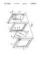
- FIG. 1is a perspective view of a lighted picture frame constructed in accordance with the present invention.
- FIG. 2is a back view of the inner frame.
- FIG. 3is a back view of the back portion.
- FIG. 4is a cross sectional view of FIG. 2 taken along lines 2--2.
- FIG. 5is a perspective view of the light and connector assembly.
- FIG. 6is a perspective view of a portion of the alternate connector.
- FIG. 7is a side view of the alternate back assembly as assembled.
- FIG. 8is a rear view of the back view of the back section.
- FIG. 9is a rear view of the back.
- FIG. 10a rear view of the back section of an alternative back assembly.
- the lighted picture frame assembly (10)includes an inner frame (11) of unitary molded construction made of opaque material such as polyester or phenolic plastics.
- the frame (11)has outer walls (12) and an inner walls (13) which form channels (14).
- Inner walls (13)include curved wall faces (13a) (13b) inner edges (13c) and curved mirrored members (13d). The edges provide a partial covering for a 3D picture to enhance the depth for the viewer.
- the channel member 14receives battery terminals 15, 15a and batteries 16, 16a which provide a power source.
- Inside wall 13bends to form a gap (17) at the top and bottom of each side. The other side of the gap is formed by flange corner (18).
- the gap, which is formed at each inside wall endis used to support an end of an optical member (20).
- Optical members (20)are positioned along opposite sides of the frame and perpendicular to inside walls (13, 13a).
- a plurality of lights (21)are mounted directly behind optical members (20). Each light is conductively attached to a printed circuit board by conductive members (22). Conductive wires not shown are used to connect each printed circuit board (23) with the terminal members (24) on each board. Each printed circuit board has an inner face painted white to enhance the illumination provided by the lights. Slots (25) are formed in the inner wall (12) of the frame for receiving and supporting each printed circuit board. Resilient metal devices (26) are also utilized to secure each printed circuit board. Each resilient device grounds the corresponding circuit board.
- filaments of the bulbs (21) located along each inside wallare arranged more or less on the focal line of the optic member.
- the optic member (20) of the preferred embodimentis a plano-convex cross sectioned acrylic bar adjacent the bulbs (21) to direct light rays on an incline downwardly and the throw the light onto the surface of 3D picture such that the small plastic semicylinders coated on the surface of the 3D picture are displayed with full effect.
- the assembly (10)includes an outer frame (10a), a glass sheet (10b), an inner frame (11) a 3D picture (10c) and a back portion (10d).
- the outer edges of the pictureextend beyond the inner edges (13c) of the inner frame (11).
- Adjacent each inner edge (13c)is a curved mirror member (13d) which provides in part a curved support surface for the picture.
- Each curved wallhas an inside face provided with a reflective surface (13e).
- Rear supporting surface (30) as illustrated in FIGS. 1 and 4is wedge shaped at the top and bottom to provide a curved supporting surface.
- the picture frame assemblythis provides a portal opening 31 to support a 3D picture at least a distance of millimeters from the opening.
- the pictureis supported by means that positions the picture at least a distance of three millimeters from the portal opening.
- the channel (14)includes a switch (40) and an external power supply plug (41).
- the plugpermits use of the assembly without batteries and the switch electrically connects or disconnects the printed circuit boards to batteries or an external power source as is well known in the art.
- the switchalso is fuctioned as a light dimmer by connecting a diode (61) serially to the bulbs. Through the electrical power the bulbs (21) are illuminated to display the 3D picture.
- FIG. 3illustrates the back portion 40 of the assembly,
- the back portionincludes a stand 42.
- the bulbsare illuminated to pass light through the optical members.
- the lightreflects off the mirrors positioned along side of the 3D picture.
- the lightreflects off the mirrors positioned along side of the 3D picture.
- the curved mounting supports for the picture along with the scattering lightdisplays the picture and creates an image of added depth. The enhanced depth to the viewer is even further projected by the extended assembly.
- the back portionincludes a stand 42.
- FIGS. 5-6further illustrate alternative details of the frame assembly.
- FIG. 5discloses the use of flat conductors 46 that are connected to lamp leads 47 and held in a grooved channel 54. Tapered grooves 55 form a socket for the leads for attachment to the conductors 46.
- FIGS. 7-9an alternative backing sections unassembled.
- FIG. 7is a cross sectional view of FIGS. 8 and 9 in assembled form.
- FIG. 7illustrates an outer back section 51 and a back 52. The section snap fit together as illustrated in FIG. 7.
- stand 42a and tab 53are formed integral with the back 52. Removal of back 52 permits changing of the picture.
- FIG. 10illustrates another embodiment of the frame assembly.
- the assemblyincludes a tubular bulb (60) used instead of the individual bulbs of the previous embodiments.
- the bulbis electrically connected to the power source without the use of the printed circuit board by conventional means.
Landscapes
- Business, Economics & Management (AREA)
- Accounting & Taxation (AREA)
- Marketing (AREA)
- Physics & Mathematics (AREA)
- General Physics & Mathematics (AREA)
- Engineering & Computer Science (AREA)
- Theoretical Computer Science (AREA)
- Mirrors, Picture Frames, Photograph Stands, And Related Fastening Devices (AREA)
- Illuminated Signs And Luminous Advertising (AREA)
Abstract
Description
Since the introduction of the Victorian stereoscope, creators of 3D images have presented illusory images. Until today however, a 3D picture was not an available creation to the ordinary photographer. Accordingly, there has never been a need for addressing the mounting process of a 3D picture. With the introduction of the 3D camera for the amateur photographer, there is now a need for a frame to present a 3D image without loosing the illusory effect.
Ordinary picture frames for two dimensional pictures present a picture with the edges of the image in contact with the rim of the frame face against the glass or transparent cover. When a 3D picture is used in such a frame, the 3D effect becomes compressed as the details of the picture approach the edges. The illusory depth of the image is erased by the mount.
A review of prior image displays teaches that illuminated picture frames are well known. For example, Robison et al. U.S. Pat. No. 3,318,032 discloses an illuminated display frame having light diffusing transparent prismatic lists and a picture displayed in an outer frame mounted on the lists. Robison does not attempt to solve the problems created in mounting 3D pictures.
Other prior art mountings which teach the use of lights to illuminate pictures are disclosed in the patents to Reefe U.S. Pat. No. 2,549,928, Diceglie U.S. Pat. No. 4,096,656 and Torrence U.S. Pat. No. 4,922,384. The art of mounting 3D pictures is not addressed by any of these patents. Accordingly, there is a need for a picture frame specifically designed to enhance the magical effects displayed by a 3D picture .
FIG. 1 is a perspective view of a lighted picture frame constructed in accordance with the present invention.
FIG. 2 is a back view of the inner frame.
FIG. 3 is a back view of the back portion.
FIG. 4 is a cross sectional view of FIG. 2 taken alonglines 2--2.
FIG. 5 is a perspective view of the light and connector assembly.
FIG. 6 is a perspective view of a portion of the alternate connector.
FIG. 7 is a side view of the alternate back assembly as assembled.
FIG. 8 is a rear view of the back view of the back section.
FIG. 9 is a rear view of the back.
FIG. 10 a rear view of the back section of an alternative back assembly.
A preferred embodiment of a lighted picture frame assembly (10) constructed in accordance with the present invention will now be described with reference to the drawings.
With reference to FIGS. 1-4 the lighted picture frame assembly (10) includes an inner frame (11) of unitary molded construction made of opaque material such as polyester or phenolic plastics. The frame (11) has outer walls (12) and an inner walls (13) which form channels (14). Inner walls (13) include curved wall faces (13a) (13b) inner edges (13c) and curved mirrored members (13d). The edges provide a partial covering for a 3D picture to enhance the depth for the viewer. Thechannel member 14 receivesbattery terminals 15, 15a andbatteries 16, 16a which provide a power source. Inside wall 13b ends to form a gap (17) at the top and bottom of each side. The other side of the gap is formed by flange corner (18). The gap, which is formed at each inside wall end is used to support an end of an optical member (20). Optical members (20) are positioned along opposite sides of the frame and perpendicular to inside walls (13, 13a).
A plurality of lights (21) are mounted directly behind optical members (20). Each light is conductively attached to a printed circuit board by conductive members (22). Conductive wires not shown are used to connect each printed circuit board (23) with the terminal members (24) on each board. Each printed circuit board has an inner face painted white to enhance the illumination provided by the lights. Slots (25) are formed in the inner wall (12) of the frame for receiving and supporting each printed circuit board. Resilient metal devices (26) are also utilized to secure each printed circuit board. Each resilient device grounds the corresponding circuit board.
As further illustrated in FIGS. 1-4, filaments of the bulbs (21) located along each inside wall are arranged more or less on the focal line of the optic member. The optic member (20) of the preferred embodiment is a plano-convex cross sectioned acrylic bar adjacent the bulbs (21) to direct light rays on an incline downwardly and the throw the light onto the surface of 3D picture such that the small plastic semicylinders coated on the surface of the 3D picture are displayed with full effect.
Turning back to FIG. 1, the assembly (10) includes an outer frame (10a), a glass sheet (10b), an inner frame (11) a 3D picture (10c) and a back portion (10d). After assembly, the outer edges of the picture extend beyond the inner edges (13c) of the inner frame (11). Adjacent each inner edge (13c) is a curved mirror member (13d) which provides in part a curved support surface for the picture. Each curved wall has an inside face provided with a reflective surface (13e). Rear supporting surface (30) as illustrated in FIGS. 1 and 4 is wedge shaped at the top and bottom to provide a curved supporting surface.
The picture frame assembly this provides a portal opening 31 to support a 3D picture at least a distance of millimeters from the opening. The picture is supported by means that positions the picture at least a distance of three millimeters from the portal opening.
As further shown in FIG. 2, the channel (14) includes a switch (40) and an external power supply plug (41). The plug permits use of the assembly without batteries and the switch electrically connects or disconnects the printed circuit boards to batteries or an external power source as is well known in the art. The switch also is fuctioned as a light dimmer by connecting a diode (61) serially to the bulbs. Through the electrical power the bulbs (21) are illuminated to display the 3D picture.
FIG. 3 illustrates the back portion 40 of the assembly, The back portion includes a stand 42.
In operation, the bulbs are illuminated to pass light through the optical members. The light reflects off the mirrors positioned along side of the 3D picture. The light reflects off the mirrors positioned along side of the 3D picture. The curved mounting supports for the picture along with the scattering light displays the picture and creates an image of added depth. The enhanced depth to the viewer is even further projected by the extended assembly. The back portion includes a stand 42.
FIGS. 5-6 further illustrate alternative details of the frame assembly. FIG. 5 discloses the use offlat conductors 46 that are connected to lamp leads 47 and held in agrooved channel 54.Tapered grooves 55 form a socket for the leads for attachment to theconductors 46.
FIGS. 7-9 an alternative backing sections unassembled. FIG. 7 is a cross sectional view of FIGS. 8 and 9 in assembled form. FIG. 7 illustrates anouter back section 51 and a back 52. The section snap fit together as illustrated in FIG. 7. As shown in FIG. 9stand 42a andtab 53 are formed integral with the back 52. Removal of back 52 permits changing of the picture.
FIG. 10 illustrates another embodiment of the frame assembly. The assembly includes a tubular bulb (60) used instead of the individual bulbs of the previous embodiments. The bulb is electrically connected to the power source without the use of the printed circuit board by conventional means.
Claims (5)
1. An illuminated picture frame assembly for a 3D picture, comprising;
a back portion, said back portion having a stand means for supporting said frame assembly in an upright position,
an inner frame housing, said inner frame housing having two inside walls, each inside wall having an inner facing reflective surface and a support means for supporting said picture, said support means curved to form a curved support surface for said picture such that said picture conforms to a shape of said curve support surface while supported on said curved support surface, inner edge portions, said edge portions forming a portal opening for viewing said picture, said portal opening of smaller area that an are of said picture,
at least two optical members extending along said inner edge portions, a plurality of spaced apart light sources within the inner frame housing,
a power sources conductively connected to a printed circuit board for illuminating said light sources, and
switching means adapted to close a circuit containing said power source and said light sources.
2. The illuminated picture frame of claim 1 further comprising, a rear support surface formed on a back portion surface for receiving a rear face of said picture, said rear support having a wedge shaped surface correspondingly mating with said curved support surface for supporting said picture.
3. The illuminated picture frame of claim 1 further comprising an outer frame, said outer frame including a glass sheet.
4. The illuminated picture frame of claim 1 further comprising picture support means for supporting said picture at least a distance of 3 millimeters from said portal opening.
5. The illuminated picture frame assembly of claim 1 further comprising tapered grooves formed in said inner frame, said grooves forming sockets to receive lamp leads for electrical attachments to conductors.
Priority Applications (1)
| Application Number | Priority Date | Filing Date | Title |
|---|---|---|---|
| US07/823,460US5265357A (en) | 1992-01-22 | 1992-01-22 | Magic 3D effect enhancing frame |
Applications Claiming Priority (1)
| Application Number | Priority Date | Filing Date | Title |
|---|---|---|---|
| US07/823,460US5265357A (en) | 1992-01-22 | 1992-01-22 | Magic 3D effect enhancing frame |
Publications (1)
| Publication Number | Publication Date |
|---|---|
| US5265357Atrue US5265357A (en) | 1993-11-30 |
Family
ID=25238829
Family Applications (1)
| Application Number | Title | Priority Date | Filing Date |
|---|---|---|---|
| US07/823,460Expired - Fee RelatedUS5265357A (en) | 1992-01-22 | 1992-01-22 | Magic 3D effect enhancing frame |
Country Status (1)
| Country | Link |
|---|---|
| US (1) | US5265357A (en) |
Cited By (59)
| Publication number | Priority date | Publication date | Assignee | Title |
|---|---|---|---|---|
| US5555654A (en)* | 1994-10-31 | 1996-09-17 | Hermann; Mark D. | Frames having lighting to illuminate glass etchings |
| US5915857A (en)* | 1991-12-16 | 1999-06-29 | Gallagher; Gerald B. | Method and apparatus using pins to hold an item to be mounted in a display device |
| US5943801A (en)* | 1998-07-29 | 1999-08-31 | Wilkinson; Kirk | System and method for backlighting a display |
| FR2782559A1 (en)* | 1998-08-24 | 2000-02-25 | Marc Charbonneaux | Method to provide definition of depth on original images; involves supplying additional tangential visible or invisible electromagnetic radiation in front of, behind and within plane of image |
| EP0993237A2 (en)* | 1998-10-05 | 2000-04-12 | Matsushita Electric Industrial Co., Ltd. | Light irradiation method |
| US6174065B1 (en)* | 1999-04-05 | 2001-01-16 | Paul Schurch | Modular illuminated panel display system |
| WO2001017637A1 (en)* | 1999-09-03 | 2001-03-15 | Privas Yves E | Single and multiple image display apparatus for works of art and photographs |
| US6293038B1 (en)* | 1994-07-01 | 2001-09-25 | Cherng Chang | Frame |
| US6390648B1 (en)* | 1999-09-03 | 2002-05-21 | Yves E. Privas | Display apparatus for works of art |
| US6536146B2 (en)* | 2001-05-25 | 2003-03-25 | Steven Ericson | Movement effect visual display |
| US6594934B1 (en)* | 1999-01-25 | 2003-07-22 | Wing Hang Wong | Display apparatus |
| US6668477B1 (en) | 2002-06-21 | 2003-12-30 | Shellie J. Cannady | Picture frame providing three dimensional visual effects |
| US6776505B1 (en)* | 2002-10-04 | 2004-08-17 | Dewitt Shane | Illuminated image night light |
| US20040226209A1 (en)* | 2003-05-12 | 2004-11-18 | Bernardo Ayala | Picture frame with integrated lighting |
| US20050007754A1 (en)* | 2003-07-10 | 2005-01-13 | Ricky Creel | Lighted image display |
| US6845578B1 (en)* | 2001-08-03 | 2005-01-25 | Stephen J. Lucas | Illuminated multi-image display system and method therefor |
| US20050117330A1 (en)* | 2003-12-02 | 2005-06-02 | Li-Han Chen | Light illuminated photo frame |
| US20050172532A1 (en)* | 2004-02-09 | 2005-08-11 | Patty Barron | Apparatus for displaying an illuminated object |
| US20050193543A1 (en)* | 2004-03-02 | 2005-09-08 | Eastman Kodak Company | Mounting an oled donor sheet to frames |
| US20060098415A1 (en)* | 2004-11-10 | 2006-05-11 | Ki-Jung Kim | Plasma display panel (PDP) supporting member and PDP including the supporting member |
| USD527192S1 (en) | 2005-02-18 | 2006-08-29 | Burnes Operating Company Llc | Photo frame |
| USD527534S1 (en) | 2005-06-16 | 2006-09-05 | Burnes Operating Company Llc | Photo frame |
| USD527533S1 (en) | 2005-02-18 | 2006-09-05 | Burnes Operating Company Llc | Photo frame |
| USD528309S1 (en) | 2005-04-28 | 2006-09-19 | Burnes Operating Company Llc | Photo frame |
| US7107712B2 (en)* | 2000-06-06 | 2006-09-19 | Christine Ann Mueller | Lighting system |
| USD529300S1 (en) | 2005-02-25 | 2006-10-03 | Burnes Operating Company Llc | Photo frame |
| USD529722S1 (en) | 2005-06-16 | 2006-10-10 | Burnes Operating Company Llc | Photo frame |
| US20060254156A1 (en)* | 2003-04-16 | 2006-11-16 | Giampaolo Targetti | Embedded or ceiling fitted illumination device with back reproducing decorative images |
| US20070017132A1 (en)* | 2005-05-10 | 2007-01-25 | Curtis Donald R | Display framing systems and related methods |
| US20070041168A1 (en)* | 2003-08-21 | 2007-02-22 | Dodd Caroline M | Luminous container |
| US20070062087A1 (en)* | 2005-08-24 | 2007-03-22 | Clifford Ross | Frame system |
| USD541054S1 (en) | 2005-02-18 | 2007-04-24 | Burnes Operating Co. Llc | Concave photo frame |
| US20080024047A1 (en)* | 2006-07-24 | 2008-01-31 | Juo Chun J | Decorative door for cooler |
| US20080034633A1 (en)* | 2006-08-10 | 2008-02-14 | Yin Kwong Tang | Illuminated picture frame |
| USD578311S1 (en) | 2006-06-29 | 2008-10-14 | Burnes Home Accents, Llc | Picture frame |
| US20090034252A1 (en)* | 2007-08-02 | 2009-02-05 | Engel Hartmut S | Luminaire |
| US20090086467A1 (en)* | 2007-03-30 | 2009-04-02 | Stuhr Darlene K | Lighted background for fish tanks and the like |
| KR100902647B1 (en) | 2009-01-23 | 2009-06-15 | 박준영 | Illuminated Picture Frames for Stereoscopic Exhibits |
| US7661216B1 (en) | 2008-10-09 | 2010-02-16 | Wampler Richard P | Illuminated picture frame |
| US20100088941A1 (en)* | 2008-10-10 | 2010-04-15 | Shiqi Zhu | Frame with illuminated picture |
| EP2253251A1 (en)* | 2009-05-22 | 2010-11-24 | Weiland, Klaus | Picture frame |
| US20110002128A1 (en)* | 2009-07-01 | 2011-01-06 | Facesme Llc | Lighting fixture and method for creating visual effects and method for creating a distorted image |
| US20110051399A1 (en)* | 2009-09-02 | 2011-03-03 | Terrence Hickey | Portable illuminated display device |
| US7942542B1 (en)* | 2008-06-20 | 2011-05-17 | Gary Dunn | Back lighted replaceable image sheet display apparatus |
| US20110157860A1 (en)* | 2009-12-31 | 2011-06-30 | Hong Fu Jin Precision Industry (Shenzhen) Co., Ltd. | Display device having foldable plates |
| US20150047996A1 (en)* | 2013-08-16 | 2015-02-19 | Richard LEVITAN | Display case assembly for phonograph record and cover |
| US20150107142A1 (en)* | 2013-04-15 | 2015-04-23 | Rose Displays Ltd | Illuminable double-sided frame arrangement |
| US20180306972A1 (en)* | 2017-04-19 | 2018-10-25 | Omachron Intellectual Property Inc. | Led light source |
| US10143316B2 (en) | 2015-06-30 | 2018-12-04 | The Hillman Group, Inc. | Wall anchor assemblies and related wall mount systems |
| US10197217B2 (en) | 2015-06-30 | 2019-02-05 | The Hillman Group, Inc. | Wall anchor assemblies |
| US10258180B2 (en) | 2015-11-06 | 2019-04-16 | The Hillman Group, Inc. | Hook rail |
| US10274189B2 (en)* | 2017-03-09 | 2019-04-30 | David Frederick Wagoner | Mechanism for display of art work backlit by LED lighting |
| US10390618B2 (en) | 2016-02-15 | 2019-08-27 | The Hillman Group, Inc. | Wall mountable object support system and related accessories |
| US10394075B2 (en) | 2016-10-11 | 2019-08-27 | Coretronic Corporation | Transparent display device |
| US10539266B2 (en) | 2015-06-30 | 2020-01-21 | The Hillman Group, Inc. | Wall anchors |
| US10799025B2 (en) | 2015-10-23 | 2020-10-13 | The Hillman Group, Inc. | Wall anchors and related wall mount systems |
| US11105969B2 (en)* | 2018-02-09 | 2021-08-31 | Panasonic Intellectual Property Management Co., Ltd. | Display device and input device |
| US11204460B2 (en) | 2017-04-19 | 2021-12-21 | Omachron Intellectual Property Inc. | LED light source |
| DE102022108525A1 (en) | 2022-04-08 | 2023-10-12 | Birgit Stigter | Framing system for a picture or other work of art |
Citations (7)
| Publication number | Priority date | Publication date | Assignee | Title |
|---|---|---|---|---|
| US2579230A (en)* | 1949-04-13 | 1951-12-18 | Joe W Giboney | Illuminated license plate frame |
| US2677909A (en)* | 1951-11-01 | 1954-05-11 | Heydenryk Henry | Illuminated picture frame |
| US3318032A (en)* | 1965-08-12 | 1967-05-09 | Edward C Robison | Illuminated display frame |
| US4791540A (en)* | 1987-05-26 | 1988-12-13 | Minnesota Mining And Manufacturing Company | Light fixture providing normalized output |
| US4819355A (en)* | 1987-07-28 | 1989-04-11 | Wolo Manufacturing Corporation | Motorcycle license plate frame |
| US4922384A (en)* | 1989-06-08 | 1990-05-01 | Mechtronics Corporation | Illuminated display with half-silvered mirrors and discrete refractor plates |
| US4974354A (en)* | 1989-04-21 | 1990-12-04 | Hembrook Jr Norbert | Visual display device for vehicles |
- 1992
- 1992-01-22USUS07/823,460patent/US5265357A/ennot_activeExpired - Fee Related
Patent Citations (7)
| Publication number | Priority date | Publication date | Assignee | Title |
|---|---|---|---|---|
| US2579230A (en)* | 1949-04-13 | 1951-12-18 | Joe W Giboney | Illuminated license plate frame |
| US2677909A (en)* | 1951-11-01 | 1954-05-11 | Heydenryk Henry | Illuminated picture frame |
| US3318032A (en)* | 1965-08-12 | 1967-05-09 | Edward C Robison | Illuminated display frame |
| US4791540A (en)* | 1987-05-26 | 1988-12-13 | Minnesota Mining And Manufacturing Company | Light fixture providing normalized output |
| US4819355A (en)* | 1987-07-28 | 1989-04-11 | Wolo Manufacturing Corporation | Motorcycle license plate frame |
| US4974354A (en)* | 1989-04-21 | 1990-12-04 | Hembrook Jr Norbert | Visual display device for vehicles |
| US4922384A (en)* | 1989-06-08 | 1990-05-01 | Mechtronics Corporation | Illuminated display with half-silvered mirrors and discrete refractor plates |
Cited By (78)
| Publication number | Priority date | Publication date | Assignee | Title |
|---|---|---|---|---|
| US5915857A (en)* | 1991-12-16 | 1999-06-29 | Gallagher; Gerald B. | Method and apparatus using pins to hold an item to be mounted in a display device |
| US6293038B1 (en)* | 1994-07-01 | 2001-09-25 | Cherng Chang | Frame |
| US5555654A (en)* | 1994-10-31 | 1996-09-17 | Hermann; Mark D. | Frames having lighting to illuminate glass etchings |
| US5943801A (en)* | 1998-07-29 | 1999-08-31 | Wilkinson; Kirk | System and method for backlighting a display |
| FR2782559A1 (en)* | 1998-08-24 | 2000-02-25 | Marc Charbonneaux | Method to provide definition of depth on original images; involves supplying additional tangential visible or invisible electromagnetic radiation in front of, behind and within plane of image |
| WO2000011640A1 (en)* | 1998-08-24 | 2000-03-02 | Marc Charbonneaux | Additional rear and front lights to an image |
| EP0993237A2 (en)* | 1998-10-05 | 2000-04-12 | Matsushita Electric Industrial Co., Ltd. | Light irradiation method |
| US6594934B1 (en)* | 1999-01-25 | 2003-07-22 | Wing Hang Wong | Display apparatus |
| US6174065B1 (en)* | 1999-04-05 | 2001-01-16 | Paul Schurch | Modular illuminated panel display system |
| WO2001017637A1 (en)* | 1999-09-03 | 2001-03-15 | Privas Yves E | Single and multiple image display apparatus for works of art and photographs |
| US6390648B1 (en)* | 1999-09-03 | 2002-05-21 | Yves E. Privas | Display apparatus for works of art |
| US7107712B2 (en)* | 2000-06-06 | 2006-09-19 | Christine Ann Mueller | Lighting system |
| US6536146B2 (en)* | 2001-05-25 | 2003-03-25 | Steven Ericson | Movement effect visual display |
| US6845578B1 (en)* | 2001-08-03 | 2005-01-25 | Stephen J. Lucas | Illuminated multi-image display system and method therefor |
| US6668477B1 (en) | 2002-06-21 | 2003-12-30 | Shellie J. Cannady | Picture frame providing three dimensional visual effects |
| US6776505B1 (en)* | 2002-10-04 | 2004-08-17 | Dewitt Shane | Illuminated image night light |
| US20060254156A1 (en)* | 2003-04-16 | 2006-11-16 | Giampaolo Targetti | Embedded or ceiling fitted illumination device with back reproducing decorative images |
| US20040226209A1 (en)* | 2003-05-12 | 2004-11-18 | Bernardo Ayala | Picture frame with integrated lighting |
| US20050007754A1 (en)* | 2003-07-10 | 2005-01-13 | Ricky Creel | Lighted image display |
| US20070041168A1 (en)* | 2003-08-21 | 2007-02-22 | Dodd Caroline M | Luminous container |
| US20050117330A1 (en)* | 2003-12-02 | 2005-06-02 | Li-Han Chen | Light illuminated photo frame |
| US7146760B2 (en) | 2004-02-09 | 2006-12-12 | Patty Barron | Apparatus for displaying an illuminated object |
| US20050172532A1 (en)* | 2004-02-09 | 2005-08-11 | Patty Barron | Apparatus for displaying an illuminated object |
| US20050193543A1 (en)* | 2004-03-02 | 2005-09-08 | Eastman Kodak Company | Mounting an oled donor sheet to frames |
| US7032285B2 (en)* | 2004-03-02 | 2006-04-25 | Eastman Kodak Company | Mounting an OLED donor sheet to frames |
| US20060098415A1 (en)* | 2004-11-10 | 2006-05-11 | Ki-Jung Kim | Plasma display panel (PDP) supporting member and PDP including the supporting member |
| USD541054S1 (en) | 2005-02-18 | 2007-04-24 | Burnes Operating Co. Llc | Concave photo frame |
| USD527533S1 (en) | 2005-02-18 | 2006-09-05 | Burnes Operating Company Llc | Photo frame |
| USD527192S1 (en) | 2005-02-18 | 2006-08-29 | Burnes Operating Company Llc | Photo frame |
| USD529300S1 (en) | 2005-02-25 | 2006-10-03 | Burnes Operating Company Llc | Photo frame |
| USD528309S1 (en) | 2005-04-28 | 2006-09-19 | Burnes Operating Company Llc | Photo frame |
| US7784207B2 (en)* | 2005-05-10 | 2010-08-31 | Lighted Promotions, Inc. | Display framing systems and related methods |
| US20070017132A1 (en)* | 2005-05-10 | 2007-01-25 | Curtis Donald R | Display framing systems and related methods |
| USD529722S1 (en) | 2005-06-16 | 2006-10-10 | Burnes Operating Company Llc | Photo frame |
| USD527534S1 (en) | 2005-06-16 | 2006-09-05 | Burnes Operating Company Llc | Photo frame |
| US20070062087A1 (en)* | 2005-08-24 | 2007-03-22 | Clifford Ross | Frame system |
| US7536814B2 (en)* | 2005-08-24 | 2009-05-26 | Clifford Ross | Frame system |
| USD578311S1 (en) | 2006-06-29 | 2008-10-14 | Burnes Home Accents, Llc | Picture frame |
| US20080024047A1 (en)* | 2006-07-24 | 2008-01-31 | Juo Chun J | Decorative door for cooler |
| US20080034633A1 (en)* | 2006-08-10 | 2008-02-14 | Yin Kwong Tang | Illuminated picture frame |
| US20090086467A1 (en)* | 2007-03-30 | 2009-04-02 | Stuhr Darlene K | Lighted background for fish tanks and the like |
| US7726829B2 (en) | 2007-03-30 | 2010-06-01 | Stuhr Darlene K | Lighted background for fish tanks and the like |
| US20090034252A1 (en)* | 2007-08-02 | 2009-02-05 | Engel Hartmut S | Luminaire |
| US7841738B2 (en)* | 2007-08-02 | 2010-11-30 | Engel Hartmut S | Luminaire having light emitting diodes (leds) directed to a reflector |
| US7942542B1 (en)* | 2008-06-20 | 2011-05-17 | Gary Dunn | Back lighted replaceable image sheet display apparatus |
| US7661216B1 (en) | 2008-10-09 | 2010-02-16 | Wampler Richard P | Illuminated picture frame |
| US20100088941A1 (en)* | 2008-10-10 | 2010-04-15 | Shiqi Zhu | Frame with illuminated picture |
| KR100902647B1 (en) | 2009-01-23 | 2009-06-15 | 박준영 | Illuminated Picture Frames for Stereoscopic Exhibits |
| EP2253251A1 (en)* | 2009-05-22 | 2010-11-24 | Weiland, Klaus | Picture frame |
| US8562182B2 (en)* | 2009-07-01 | 2013-10-22 | FacesMe, LLC | Lighting fixture and method for creating visual effects and method for creating a distorted image |
| US20110002128A1 (en)* | 2009-07-01 | 2011-01-06 | Facesme Llc | Lighting fixture and method for creating visual effects and method for creating a distorted image |
| US20110051399A1 (en)* | 2009-09-02 | 2011-03-03 | Terrence Hickey | Portable illuminated display device |
| US8231239B2 (en)* | 2009-09-02 | 2012-07-31 | Terrence Peter Hickey | Portable illuminated display device |
| US8243471B2 (en)* | 2009-12-31 | 2012-08-14 | Hong Fu Jin Precision Industry (Shenzhen) Co., Ltd. | Display device having foldable plates |
| US20110157860A1 (en)* | 2009-12-31 | 2011-06-30 | Hong Fu Jin Precision Industry (Shenzhen) Co., Ltd. | Display device having foldable plates |
| US20150107142A1 (en)* | 2013-04-15 | 2015-04-23 | Rose Displays Ltd | Illuminable double-sided frame arrangement |
| US9192255B2 (en)* | 2013-04-15 | 2015-11-24 | Rose Displays Ltd. | Illuminable double-sided frame arrangement |
| US20150047996A1 (en)* | 2013-08-16 | 2015-02-19 | Richard LEVITAN | Display case assembly for phonograph record and cover |
| US9139358B2 (en)* | 2013-08-16 | 2015-09-22 | Richard LEVITAN | Display case assembly for phonograph record and cover |
| US10743685B2 (en) | 2015-06-30 | 2020-08-18 | The Hillman Group, Inc. | Wall anchor assemblies and related wall mount systems |
| US10197217B2 (en) | 2015-06-30 | 2019-02-05 | The Hillman Group, Inc. | Wall anchor assemblies |
| US12279707B2 (en) | 2015-06-30 | 2025-04-22 | The Hillman Group, Inc. | Wall anchor assemblies and related wall mount systems |
| US10143316B2 (en) | 2015-06-30 | 2018-12-04 | The Hillman Group, Inc. | Wall anchor assemblies and related wall mount systems |
| US10539266B2 (en) | 2015-06-30 | 2020-01-21 | The Hillman Group, Inc. | Wall anchors |
| US10724677B2 (en) | 2015-06-30 | 2020-07-28 | The Hillman Group, Inc. | Wall anchor assemblies |
| US11300245B2 (en) | 2015-06-30 | 2022-04-12 | The Hillman Group, Inc. | Wall anchor assemblies |
| US10799025B2 (en) | 2015-10-23 | 2020-10-13 | The Hillman Group, Inc. | Wall anchors and related wall mount systems |
| US11815223B2 (en) | 2015-10-23 | 2023-11-14 | The Hillman Group, Inc. | Wall anchors and related wall mount systems |
| US10258180B2 (en) | 2015-11-06 | 2019-04-16 | The Hillman Group, Inc. | Hook rail |
| US10390618B2 (en) | 2016-02-15 | 2019-08-27 | The Hillman Group, Inc. | Wall mountable object support system and related accessories |
| US10394075B2 (en) | 2016-10-11 | 2019-08-27 | Coretronic Corporation | Transparent display device |
| US10274189B2 (en)* | 2017-03-09 | 2019-04-30 | David Frederick Wagoner | Mechanism for display of art work backlit by LED lighting |
| US11204460B2 (en) | 2017-04-19 | 2021-12-21 | Omachron Intellectual Property Inc. | LED light source |
| US20180306972A1 (en)* | 2017-04-19 | 2018-10-25 | Omachron Intellectual Property Inc. | Led light source |
| US11644611B2 (en) | 2017-04-19 | 2023-05-09 | Omachron Intellectual Property Inc. | LED light source |
| US12078838B2 (en) | 2017-04-19 | 2024-09-03 | Omachron Intellectual Property Inc. | LED light source |
| US11105969B2 (en)* | 2018-02-09 | 2021-08-31 | Panasonic Intellectual Property Management Co., Ltd. | Display device and input device |
| DE102022108525A1 (en) | 2022-04-08 | 2023-10-12 | Birgit Stigter | Framing system for a picture or other work of art |
Similar Documents
| Publication | Publication Date | Title |
|---|---|---|
| US5265357A (en) | Magic 3D effect enhancing frame | |
| US6144360A (en) | Flat panel display system having direct monitoring and overhead projection monitoring capability | |
| US5555654A (en) | Frames having lighting to illuminate glass etchings | |
| US5696529A (en) | Flat panel monitor combining direct view with overhead projection capability | |
| US8128274B2 (en) | LED night light with projection feature | |
| US20150070938A1 (en) | LED Projection Night Light | |
| JPH10301509A (en) | Writable display sign | |
| US5788579A (en) | Illusion mirror light display | |
| US5371656A (en) | Apparatus for displaying an illuminated image and method therefor | |
| US20030103351A1 (en) | Multiple image display apparatus for works of art and photographs | |
| US6776505B1 (en) | Illuminated image night light | |
| US4818980A (en) | Operator control panel | |
| ES2273951T3 (en) | VITRINA INTERACTIVE EXHIBITOR AND ANNOUNCER OF ADS. | |
| JP2000148054A (en) | Display window | |
| JPH03219212A (en) | liquid crystal display device | |
| US7048398B2 (en) | Low profile light panel | |
| CN104903940A (en) | Illuminated frame system | |
| US6157117A (en) | Tube lamp | |
| US20050007754A1 (en) | Lighted image display | |
| KR101453257B1 (en) | Apparatus and method for sensitive lighting using LED | |
| KR200244860Y1 (en) | Lighting equipment | |
| CN216252862U (en) | Live Bracket | |
| CN214647296U (en) | Show paper theater | |
| KR870002552Y1 (en) | A advertising system | |
| JPH05265383A (en) | Signboard |
Legal Events
| Date | Code | Title | Description |
|---|---|---|---|
| REMI | Maintenance fee reminder mailed | ||
| LAPS | Lapse for failure to pay maintenance fees | ||
| FP | Lapsed due to failure to pay maintenance fee | Effective date:19971203 | |
| STCH | Information on status: patent discontinuation | Free format text:PATENT EXPIRED DUE TO NONPAYMENT OF MAINTENANCE FEES UNDER 37 CFR 1.362 |