US5265150A - Automatically configuring wireless PBX system - Google Patents
Automatically configuring wireless PBX systemDownload PDFInfo
- Publication number
- US5265150A US5265150AUS07/647,943US64794391AUS5265150AUS 5265150 AUS5265150 AUS 5265150AUS 64794391 AUS64794391 AUS 64794391AUS 5265150 AUS5265150 AUS 5265150A
- Authority
- US
- United States
- Prior art keywords
- stations
- control unit
- station
- telephone
- wireless
- Prior art date
- Legal status (The legal status is an assumption and is not a legal conclusion. Google has not performed a legal analysis and makes no representation as to the accuracy of the status listed.)
- Expired - Lifetime
Links
Images


Classifications
- H—ELECTRICITY
- H04—ELECTRIC COMMUNICATION TECHNIQUE
- H04W—WIRELESS COMMUNICATION NETWORKS
- H04W84/00—Network topologies
- H04W84/02—Hierarchically pre-organised networks, e.g. paging networks, cellular networks, WLAN [Wireless Local Area Network] or WLL [Wireless Local Loop]
- H04W84/10—Small scale networks; Flat hierarchical networks
- H04W84/16—WPBX [Wireless Private Branch Exchange]
- H—ELECTRICITY
- H04—ELECTRIC COMMUNICATION TECHNIQUE
- H04B—TRANSMISSION
- H04B7/00—Radio transmission systems, i.e. using radiation field
- H04B7/24—Radio transmission systems, i.e. using radiation field for communication between two or more posts
- H04B7/26—Radio transmission systems, i.e. using radiation field for communication between two or more posts at least one of which is mobile
- H04B7/2603—Arrangements for wireless physical layer control
- H04B7/2606—Arrangements for base station coverage control, e.g. by using relays in tunnels
- H—ELECTRICITY
- H04—ELECTRIC COMMUNICATION TECHNIQUE
- H04W—WIRELESS COMMUNICATION NETWORKS
- H04W16/00—Network planning, e.g. coverage or traffic planning tools; Network deployment, e.g. resource partitioning or cells structures
- H04W16/24—Cell structures
- H04W16/26—Cell enhancers or enhancement, e.g. for tunnels, building shadow
Definitions
- This inventionrelates to wireless private branch exchange (PBX) systems and more particularly to an arrangement for automatically configuring a plurality of terminals for operation within such a PBX system.
- PBXwireless private branch exchange
- PBXor Key
- a number of linesare provided between a group of local users and a switch in the PBX system.
- the PBX systemprovides a certain number of accesses to a remote communications exchange and also provides access for the local users to each other.
- a call made to or from the remote communications exchangemust first access the switch, which then routes the call to its destination.
- a call made from one local user to anothermust also access the switch which similarly routes the call to its destination.
- the PBX switchreduces the number of lines between the group of local users and the remote communications exchange, a substantial amount of wiring is still required between the switch and the local users.
- Both a customer and a manufacturer of PBX systemsbenefit when the amount of wiring required for installation of the PBX system is reduced. If installable by the customer, such a system, has the potential of saving both time and expense for the customer, while providing a marketing advantage for the manufacturer. Much of the equipment for small PBX systems is compact and self-contained enough for customers to install, but the wiring between the local units and the PBX switch generally requires outside help for both new installations and moves or rearrangements. If the wiring is eliminated or substantially simplified, most customers could install or rearrange the equipment as appropriate without assistance.
- Wireless multiple access communication systemshave also been successfully implemented in certain other applications.
- a mobile radio systemsimultaneously routes a plurality of private communications through a central base station which performs the switching necessary to interconnect the appropriate users, utilizing frequency shift keying (FSK) modulation and frequency division multiple access (FDMA).
- FSKfrequency shift keying
- FDMAfrequency division multiple access
- Another radio systemis the satellite-based communications system described in U.S. Pat. No. 4,291,409 which issued to A. Weinberg et al. on Sep. 22, 1981, wherein a central switching arrangement, phase shift keying (PSK) modulation and spread spectrum multiple access (SSMA) are used.
- PSKphase shift keying
- SSMAspread spectrum multiple access
- these systemsdo not not readily permit customer installation or rearrangement of the system equipment. Site engineering or trial-and-error placement of equipment within the system is therefore generally required. Moreover, these systems are either limited in range due to transmitter power constraints that exist under present regulations, or are also burdened by complex spread-spectrum designs.
- a wireless PBX systemconfigured in accordance with the principles of the invention overcomes the above problems. Ease of installation without site engineering or trial-and-error placement of components within the system is facilitated. Moreover, functionality and ease of operation of the system are also provided.
- the wireless PBX systemconsists of only two types of components: a control unit including a radio frequency transceiver; and fixed terminals, such as telephone stations and voice/data stations, which also include radio frequency transceivers.
- Portable handsetsalso may be included in the system to allow for customer mobility. The system therefore advantageously uses radio to achieve both wire replacement which allows for customer installation or rearrangement, and mobility which allows for customer convenience and productivity.
- some of the fixed terminalsare tasked to serve as radio repeaters so that area coverage may be expanded over that of a system employing a single base unit. With multiple stages or levels of repeaters, this coverage is significantly expanded. With two repeater levels, for example, the effective radius of coverage is increased approximately by a factor of 3 over a single base system.
- the PBX systemis installed simply by placing the system components in the desired locations at a premises, plugging them into line power, and performing some simple programming steps including a final step of initiating an automatic configuring process.
- This processadvantageously causes the control unit in the base unit to exchange various radio messages with the terminals, decide which terminals should serve as repeaters, and determine an appropriate frame structure wherein time slots, in which transmissions may be repeated in order to extend the operating range for the system, are provided.
- the inventionincludes an arrangement for automatically configuring a plurality of stations for operating in a wireless telephone system.
- This arrangementcomprises a control unit for connecting to a switched network and a plurality of stations for communicating with the control unit over a wireless communication channel.
- the control unitcomprises means for selecting at least a first one of the plurality of stations for providing telephone service with the control unit for selected second ones of the plurality of stations.
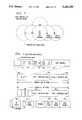
- FIG. 1is a diagram of a wireless private branch exchange (PBX) system including a PBX/KEY switch, multiple fixed location stations and multiple portable stations;
- PBXwireless private branch exchange
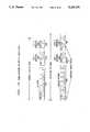
- FIG. 2is a block representation of the major functional components of the PBX/KEY switch and one of the multiple fixed stations, both depicted in FIG. 1 and operative in accordance with the invention;
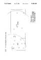
- FIG. 3shows a typical radio coverage pattern for the wireless PBX system in accordance with the invention
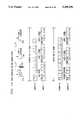
- FIG. 4shows a radio link protocol used in the communications between units within the wireless PBX system in accordance with the invention
- FIG. 5shows a table illustrating a set of possible responses in the auto-configuring of multiple stations for operation in the wireless PBX system in accordance with the invention:
- FIGS. 6, 7 and 8show flow charts illustrating the operation of the wireless PBX system of FIG. 1 in executing a three stage auto-configure operation in accordance with the invention
- FIG. 9shows a frame structure for use in an unconstrained wireless PBX system which supports four active users, in accordance with the invention.
- FIG. 10shows a frame structure for use in a specific wireless tuned PBX system which supports eight active users in accordance with the invention
- FIG. 11shows a basic wireless PBX system that uses a main transceiver and two repeaters to achieve radio coverage throughout an office/warehouse type structure
- FIG. 12shows a dual carrier wireless PBX system and frame structures for supporting these two carriers.
- a wireless private branch exchange (PBX) systemincluding a control module or PBX/KEY switch 100, multiple fixed location stations 110 through 112 and multiple portable stations 113 through 116.
- the switch 100provides central office (CO) line termination for lines 101, switching capability, feature access and control for the stations 110 through 116.
- a main control transceiver (MCT) 102 in the switch 100provides a station access interface via radio links, along with the intelligence to control a network of individual links, explained in greater detail later herein.
- the MCT 102also provides system-wide timing, auto-configuring capability, and the ability to change frame structures as conditions vary.
- a frame structureis made up of a series of time slots in which transmissions are made initially by an originating unit and may also include slots in which these transmissions are repeated by a repeater unit in order to extend the operating range of the PBX system.
- a switch suitable for use as switch 100is a MERLIN® or PARTNERTM switch (both available from AT&T) arranged for accommodating the MCT 102.
- the fixed location stations 110 through 112are capable of serving as repeaters if they are determined to be needed as such by a system auto-configure operation, described later herein. These stations are expected to be moved only occasionally. When they are moved, the auto-configure operation is repeated.
- the portable stations 113 through 116are not used as repeaters, but rather are free to be carried throughout the premises in which the system is installed.
- These portable stations 113 through 116 and the fixed location stations 110 through 112, which may be either desk or wall-mounted sets,communicate with the switch 100 via a wireless protocol which provides many of the attributes of the analog terminal line (ATL) protocol employed by AT&T in some of its wired communication switches such as the MERLIN switch.
- the wireless protocol employed in this inventionprovides control information over a radio path along with voice information between the switch 100 and each of the multiple stations 110 through 116.
- the switch 100transmits command messages via the radio path to a station. No response is required or expected of the station from the switch.
- the switch 100queries a station for information and a response message is expected.
- a stationtransmits an unprompted message to the switch 100 and a response message may or may not be expected.
- These messagesare exchanged during the time when the switch 100 polls each station. All messages received either by a station or the switch cause an acknowledgment to be returned to the sender. If the sender's message requires information to be returned, the returned information serves as the acknowledgement. If the sender's message does not require information to be returned, an explicit acknowledge message is returned.
- Such messagesinclude, for example, a request for telephone service, dialed digits, the hold function as well as the transfer function for an incoming call.
- FIG. 2there is shown a block representation of the major functional components of the PBX/KEY switch 100 and fixed station 110, both depicted in FIG. 1 and operative in a wireless PBX in accordance with the principles of the invention.
- the fixed stations 111 and 112 of FIG. 1incorporate these same basic components and are operationally identical.
- the portable stations 113 through 116also incorporate these same components and communications format, but may not be configured as repeaters.
- TDMtime division multiplexing
- the TDM formatpermits a single transmitter/receiver pair to handle a number of subchannels simultaneously, with the selection of a desired subchannel being made with simple digital logic. All transmitted information is accessible to all receivers and multiple subchannels can be combined at any station to provide higher bandwidth services (also-called bandwidth on demand). Because radio frequency (RF) paths change very little during each frame, the transmission characteristics are virtually identical for a transmit and a receive direction of a duplex link.
- RFradio frequency
- the MCT 102 shown in the switch 100 of FIG. 1is shown in greater detail in FIG. 2 and includes a control unit 201, a radio transmitter 202 and a radio receiver 203.
- the control unit 201advantageously provides the intelligence to control the network of individual links between the MCT 102 and the stations 110 through 116.
- Control unit 201may be implemented through the use of a microcomputer containing read-only-memory (ROM), random-access-memory (RAM) and through use of the proper coding.
- ROMread-only-memory
- RAMrandom-access-memory
- Such a microcomputeris known in the art and is readily available from semiconductor manufacturers such as Signetics, Intel and AMD.
- Both the MCT 102 and the station 110are operable on a plurality of communication channels.
- a carrier strength monitor 205informs the control unit 201 of an available channel which would not interfere with other nearby radio systems.
- the control unit 201configures the radio transmitter 202 and the radio receiver 203 in the MCT 102 for proper operation on the selected one of the plurality of channels when actively communicating with station 110.
- the control unit 201also provides the appropriate channel control information to the station 110.
- the transmit and receive signals of the MCT 102are coupled to, by way of example, a time division duplexer 204 which permits the transmitter 202 and the receiver 203 to both operate at different times over antenna 206.
- the telephone switching circuit 210provides central office line termination, switching capability, and feature access and control for the individual stations.
- control unit 211which interfaces with the control unit 201 in the MCT 102 and controls the operation of the circuitry in the station 110.
- this control unit 211may be implemented through the use of a microcomputer containing ROM, RAM and through use of the proper coding.
- a microcomputeris known in the art and is readily available from semiconductor manufacturers such as Signetics, Intel and AMD.
- Communications with the MCT 102are provided via a radio transmitter 212 and a radio receiver 213 in the station 110.
- the output of the transmitter 212 and input for the receiver 213are commonly coupled through a duplexer 214 to an antenna 216.
- the receiver 213demodulates voice signals transmitted by the MCT 102 and couples these signals to an acoustical device such as, for example, loudspeaker 217.
- control signals and voice signals from the radio receiverare coupled to an input of the radio transmitter where they are retransmitted in accordance with the radio link protocol described in detail later herein.
- the transmitter 212also has as its input signals originating at the station which are speech signals from a microphone 218, a system identification number from control unit 211 and opcode data representative of entries on a keypad 219, all of which it transmits to the MCT 102.
- the key pad 219is used for entering dial digits and control functions executable by the control unit 211 or transmitted to the MCT 102.
- the bandsupports 13 RF carriers spaced at 2 MHz intervals.
- a wireless communication systemis capable of operating at one of a selectable number of frequencies in order to avoid interference.
- Communication between the MCT 102 and the individual stationsis provided with a 1 Mbps throughput, at approximately 0.5 Mbps in each direction. This rate is satisfactory for most applications.
- ADPCM voice channel codingan approximately 1 Mbps system allows up to 12 duplex voice channels with ample system and station overhead for each carrier.
- each transceivertransmitter and receiver combination
- the coverage of each transceiveris shown as a circle for illustrating a typical range of coverage provided by each unit.
- the MCT or level 0 unitcontrols the radio operation and provides the basic coverage.
- the level-1 transceiversare all located within the radius of the MCT coverage.
- the level-2 transceiversare located within the radius of one or more level-1 transceiver units thereby obtaining coverage from one of these units.
- the repeatersare shown at the limit of the range of coverage, they, of course, may be otherwise located. No wiring to the remote units is needed other that that which provides line power.
- FIG. 4shows the basic radio link protocol used in communications between units within the wireless PBX system.
- This link protocoluses a basic frame which is separated into 6 segments 410 through 460 with each segment being used for sending control and voice channel information from a specific set of units. These six frame segments are also defined in Table I which illustrates the use of these segments.
- downlinkrefers to messages being sent from a CU, such as CU 201 shown in FIG. 2, to the stations or from the repeaters to the stations.
- uplinkrefers to those messages being sent to the CU from both the stations and the repeaters.
- the frameallows for two levels of repeaters, fewer segments are required with fewer levels.
- FIG. 4along with the six segments are expanded views of some of the segments for illustrating the type of control information required for system operation.
- Each frame intervalbegins with a transmission by segment 410 from the CU.
- a preamblethat allows receivers to recover clock and achieve timing recovery is provided in a field 411. All messages to the repeaters and individual stations start with this preamble.
- a timing patternis inserted in this preamble to provide a reset for system clocks to insure that all subsequent transmissions are synchronized.
- a system identification (ID) number 412is also provided in messages to and from each station to insure that each station is communicating with the correct wireless system.
- a system control signal 413is provided for operations such as informing the stations of the need to change carrier frequency if interference or noise on a carrier in use is detected.
- the parameters of the frame structureare identified in a frame descriptor field 414 provided to the stations.
- a two bit field 415is used to identify the segment number.
- the CUsends 0,0 and the next level repeaters update the segment number. This number allows a station which may only hear one of the first three segment transmissions to know when to transmit (segment 4) back to the CU.
- Field 416contains the address of a specific station and field 417 contains any control information for its operation.
- Voice channels 418typically 1 through 12, complete the segment 410. These voice channels are described in greater detail later herein and with reference to FIGS. 9 and 10.
- Field 417may provide control information in a number of ways for controlling the operation of the stations.
- the information provided by field 417may, for example, be used to assign a given voice channel for a particular station when that station has requested service.
- This station control fieldmay also be used to instruct a fixed station to be a level-1 or level-2 repeater. Those stations that are configured as repeaters demodulate the incoming packet, store the data until the next segment, then repeat the control portion of the packet with the segment number increased by 1. When a station obtains communications through a repeater station, the repeater station also repeats the voice channel for that station.
- the systemis arranged to accommodate a total of 32 different telephone stations, even though a greater or lesser number of stations may be easily employed in a wireless PBX system in accordance with the principles of the invention.
- Each stationis addressed by every 32nd frame when the full number of stations are employed in the system. When a smaller number of stations are employed in the system, a fewer number of frames accordingly may be provided. And succeeding frames just add one to the immediately preceding station address for identifying each next station to be addressed in the system. If the time to cycle through a frame is relatively long, however, i.e., a few milliseconds, more than one station may be also addressed per frame.
- the level-1 repeatersgenerate the message, or a portion of it, during the second segment 420 with the two bit field updated to 1.
- the level-2 repeatersregenerate the message, or a portion of it during the third segment 430 with the two bit field identifying the segment number updated to 2.
- each stationIn transmissions back to the CU, each station responds in a station status field 441 in segment 440 within a frame that contains that station's address.
- the responsemay be a status indication or a request for service.
- One bit of the status informationis also used to identify whether a station is fixed or portable.
- the level-2 and then level-1 repeaterstake any station status and voice channel responses received without error during segment 440, and send them respectively in fields, for example fields 461 and 462 in segment 460.
- a field 463is also provided for any repeater status messages that may be necessary.
- messages received from stations with high qualityare forwarded from level-2 repeaters to level-1 repeaters in segment 450.
- messages received with high quality from stations or level-2 repeatersare forwarded from level-1 repeaters in segment 460.
- the message protocolincludes check bits in each channel transmission, so that the MCT 102, a station or repeater can recognize whether the message received is accurate and take appropriate action.
- Stationsmay (nominally) receive the same information in more than one time segment but with different quality. The station accepts the first error-free message it receives during segment 410, 420 or 430, and looks no further once it is received. The station also rejects all errored messages. Similarly, messages that contain errors are not forwarded through repeaters. If after reading the check bits, a repeater finds it has received a message containing an error, the repeater does not forward this message. Also, in order of priority, error-free messages received from a portable station directly by the MCT 102 are used first and the repeated versions ignored. Similarly, error-free messages from the portable station received from a level level-1 repeater and provided to the MCT 102 are used over those received from a level-2 repeater.
- FIG. 5there is shown a table illustrating a set of possible responses in the auto-configuring of a 15 station system and how these stations are linked (telephone service established) to the MCT 102 in the PBX/KEY switch 100, both shown in FIG. 1.
- the MCT 102is unaware of the number of stations in the system and thus cycles through 32 addresses, the maximum number assumed for this system. In the interest of drawing clarity, however, the responses for stations 25 through 41 are not shown.
- the portable stationsare placed in remote sites on premises where the customer wants service, to insure that the system provides coverage in these locations.
- the system ID number and station addressare entered into each of these stations by the customer.
- the system ID numberis obtained from a system code provided by the manufacturer with the switch 100.
- the station addresstypically comprises a 2 digit station ID number, for example, 10 through 41 which is assigned sequentially by the customer.
- the system ID number and station addressare similarly entered into each portable station in the same manner. An extra character is entered in the highest numbered station so that during programming (and after), the MCT 102 will know that this station is the last station in the system.
- the stationsAfter the sytem ID number and station address have been entered into each station but before the auto-configuring operation begins, the stations have their transmitters off. Their receivers, however, begin scanning the available carrier frequencies looking for messages from the MCT 102 with the entered system ID number. The scan cycle for a station receiver to examine all 13 carrier frequencies is approximately 1 second, so initial transmissions from the MCT 102 allow for a station to be on the wrong carrier for a short time.
- the MCT 102In order for the auto-configuring operation to begin, the MCT 102 first finds a clear (no interferers nearby) carrier frequency. Selection of a carrier frequency starts with the MCT 102 measuring receive power on each carrier frequency and choosing the one with the lowest power. Once a carrier frequency is established the MCT 102 sets up a simple two segment frame, since there are at this point in the operation no repeaters in the system, and begins transmitting. The elements of the frame are, for example, those shown in the first and fourth segments 410 and 440 of FIG. 4. The transmission is repeated to insure that all stations within range of the MCT 102 are able to monitor the carrier frequency, verify the system ID number, and respond with a station status when the MCT 102 sends the appropriate address. The station status includes the fixed/portable indicator, a signal quality measure, e.g., received power, and a bit showing whether the station has the highest address in the system.
- a signal quality measuree.g., received power
- the auto-configuring operationis initiated by activating a switch located on the MCT 102.
- this buttonWhen this button is activated, all the stations receiving the correct system ID number from the MCT 102 have their respective transmitters turned on and the auto-configuring operation is executed.
- the information shown in FIG. 5is an illustrative example of that which may be stored in a table in memory in the CU 201 of FIG. 2 during three passes of the auto-configuring operation, described in greater detail later herein and with reference to FIGS. 6, 7 and 8.
- a "0" entryindicates no (or low quality) response
- an "F”indicates good quality, fixed station response
- a "P”is a good quality, portable response.
- the MCT 102is unaware of the number of stations in the system and thus cycles through 32 addresses. If all entries were "F” or "P" in the first pass, the system would be configured with no repeaters and nothing more would have to be done. In the illustrative table, however, there are several "0" entries in this first pass and the MCT 102 is unaware of the number of stations in the system.
- the MCT 102changes to a four segment frame for one level of repeating.
- the elements of this frameare, for example, those shown in the segments 410, 420, 440 and 460 in FIG. 4.
- stations 11, 13, 14, 17, 18, and 21are instructed to serve as level-1 repeaters.
- the unlinked stationsare sequentially addressed and responses are looked for.
- the tableshows that the use of stations 11 and 18 as level-1 repeaters set up links to four more stations, 10, 16, 23, and 24.
- the response from station 24shows it has the highest address, so the MCT 102 from this pass is made aware of the number of stations in the system and that only two more stations (12, 20) need to be linked.
- the blank entries in the second roware "don't cares" and represent stations that are already linked.
- the MCT 102shifts to a six segment frame as shown in FIG. 4 to allow for two levels of repeating.
- Stations 11, and 18serve as level-1 repeaters and stations 10, 16, and 24 are sequentially instructed to act as level-2 repeaters.
- the unlinked stationsare addressed and responses are looked for.
- station 16 set as a level-2 repeaterWith station 16 set as a level-2 repeater, the remaining two stations 12 and 20 become part of the system.
- the final systemthus uses stations 11 and 18 as level-1 repeaters and 16 as a level-2 repeater.
- a positive display indication at the MCT 102which shows that all stations are linked and that the system is operating normally, is provided.
- FIGS. 6, 7 and 8there is shown in each of these FIGS. flow charts illustrating the operation of the wireless PBX system in executing a three stage auto-configure operation in accordance with the invention.
- the three stages of the auto-configure operationrespectively correspond to the first, second and third pass levels depicted in the illustrative example provided by the auto-configuration table of FIG. 5.
- the functions jointly provided by control unit 201 and illustratively, control unit 211, responsive to control unit 201, both shown in FIG. 2,are advantageously determined by a process or program respectively stored in ROM associated with each of these control units.
- step 601a counter A is initially set to a count of 10. This count is set during an initialization step when the process is first initiated and corresponds to the station address of the first one of the stations in the wireless PBX system. From step 601, the process advances to decision 602 where the number stored in step 601 is examined. If the count is less than 41 in counter A, then the process advances to step 603 where each of the stations are polled by the control unit 201 with a first control signal, the control unit providing this polling by sending out a station address corresponding to each of the individual stations.
- step 605a 0 flag, previously described herein with reference to FIG. 5, is set.
- step 606the counter A is incremented by one. From the step 606, the process returns to the step 601.
- the processadvances to decision 607 where a determination is made as to the type of station, i.e., either a fixed station or a portable station. If the type of station is a fixed station, then the process advances to the step 608 where the F0 flag described in FIG. 5 is set. If the decision 607 determines that the station is not a fixed station, then the process advances to step 609 where the P flag, which corresponds to a portable station, is set. From either step 608 or step 609, the process advances to the decision 610 where a determination is made as to whether the station then being addressed has been programmed to indicate that it is the highest or last address in the system. When 32 stations are employed in the system, this station will have address number 41. When fewer stations are employed, however, then the last one of these stations is programmed so that in its response to the control unit, it includes information that it is the last station in the system.
- the processgoes to the step 606 where the counter A is advanced and the station address for the next expected station in the system is generated by the process. If at decision 610, the station then being addressed provides information that it is the last station in the system, the process advances to step 611 where the L flag is set, this flag corresponding to the last station in the system. From the step 611, as well as from the decision 602, the process advances to decision 612 where a determination is made as to whether any 0 flags were set during the polling operation. If there were no 0 flags set, the process advances to decision 613 where it checks to see if the L flag is set. If the L flag is set, then the auto-configure process is complete and the process is exited. If a 0 flag is detected in decision 612 or the L flag not detected in decision 613, the process advances to the second stage of the auto-configure operation.
- a counter Bis initially set to a count of 10. This count is set during an initialization step when the process is first initiated. From the step 701, the process advances to decision 702 where the number or station address then stored in counter 701 is examined. If the count is less than 41 in counter B, then the process advances to decision 703 where a determination is made as to whether an FO flag described earlier herein with reference to FIG. 5 has been assigned to the station corresponding to the number then stored in counter B. If the F0 flag is not assigned to the station number then being examined, the process advances to the decision 704 where a determination is made as to whether the L flag is assigned to this station address. If the L flag is not assigned to this station address, the process advances to the step 705 wherein the counter B is incremented by one. From the step 705, the process returns to step 701.
- step 706that particular station is configured as a level-1 repeater by a second control signal provided by the control unit 201.
- this stationattempts to communicate with those stations that the MCT 102, shown in FIG. 2, was unable to reach.
- This stationis thus configured to receive and then send out the station addresses for those stations that to this point in the process have not been linked.
- step 707a counter C is set to a count of 10 reflecting the lowest address assigned to a station in the system.
- step 707the process advances to decision 708 where the count or station address contained in step 707 is examined. If the count is less than 41 in counter C, then the process advances to step 709 where the station whose address is currently stored in counter C is polled with a third control signal by the control unit contained in the fixed station then selected by the process at decision 703. If the polled station does not respond, which is detected in decision 710, the process advances to step 711 wherein the counter C is incremented by one. From the step 711, the process returns to the step 707.
- this responseis provided as a fourth control signal to the control unit 201 by the control unit contained in the fixed station then selected.
- the processthen advances to decision 712 where a determination is made as to whether a 0 flag had been assigned to this station. If the 0 flag was not assigned to this station, it reflects that this station had been addressed by the control unit 201 and the process goes to step 711. If the 0 flag was assigned to this station, it reflects that this station was not addressed by the control unit 201 and the process goes to step 713 where an R1 flag is set for the station determined at decision 703.
- the R1 flagdesignates the station identified at decision 703 as a level-1 repeater to be used in subsequent communications with the new station identified at decision 710.
- the processadvances to the decision 714 where a determination is made as to the type of station, i.e., either a fixed station or a portable station. If the type of station is a fixed station, then the process advances to the step 715 where the F1 flag, which corresponds to a fixed station found with one repeater, is set. If the decision 714 determines that the station is not a fixed station, then the process advances to step 716 where the P flag, which corresponds to a portable station, is set. From either step 715 or step 716, the process advances to the decision 717 where a determination is made as to whether the station then being addressed is the last station in the system.
- the processgoes to the step 711 where the counter C is advanced and the fixed station selected at decision 703 will attempt to contact any of the remaining unlinked stations in the system. If the station addressed at decision 717 is the last one of the stations in the system, the process advances to the step 718 where the L flag is assigned to this just detected station. From this step 718, as well as from decision 708, wherein 32 station addresses have been generated, the process goes to the step 705 where the counter B is advanced and the next detected fixed station will look for any stations remaining undetected within the system in the just described manner.
- the processadvances to decision 719 where a determination is made as to whether any 0 flags remain set after the polling operation. If there are no 0 flags still set, the process advances to decision 720 where it determines whether the L flag is set. If the L flag is set, then the auto-configure process is complete and the process is exited. If a 0 flag is detected as being set in decision 719 or a L flag not detected in decision 720, then the process advances to a third and final stage of the auto-configure operation.
- step 801a counter D is initially set to a count of 10. This count is set during an initialization step when the process is first initiated. From the step 801, the process advances to decision 802 where the number or station address then stored in counter 801 is examined. If the count is less than 41 in counter B, then the process advances to decision 803 where a determination is made as to whether an F1 flag has been assigned to the station address corresponding to the number then stored in counter D. If the F1 flag is not assigned to the station address number then being examined, the process advances to the decision 804 where a determination is made as to whether the L flag is assigned to this station address. If the L flag is not assigned to this station address, the process advances to the step 805 wherein the counter D is incremented by one. From the step 805, the process returns to step 801.
- step 806that particular station is configured as a level-2 repeater.
- this stationattempts to communicate with those stations that the level-1 repeaters were unable to reach during the second stage of the auto-configure operation.
- This stationis thus configured to receive and then send out station addresses for those stations that to this point in the process have not been linked.
- step 807a counter E is set to a count of 10 reflecting the lowest address assigned to a station in the system.
- step 807the process advances to decision 808 where the count or station address contained in step 807 is examined. If the count is less than 41 in counter E, then the process advances to step 809 where the station whose address is currently stored in counter C is polled by the control unit contained in the fixed station then selected as a level-2 repeater by the process at decision 803. If the polled station does not respond, which is detected in decision 810, the process advances to step 811 wherein the counter E is incremented by one. From the step 811, the process returns to the step 807.
- the processadvances to decision 812 where a determination is made as to whether a 0 flag is then assigned to this station. If the 0 flag is not assigned to this station, it reflects that this station has been successfully addressed either by the control unit 201 in the first stage or by a level-1 repeater in the second stage of the auto-configure operation. The process then goes to step 811. If the 0 flag is assigned to this station, however, it reflects that this station was not addressed by the control unit 201 nor a level-1 repeater and the process goes to step 813 where an R2 flag is set Thus the total number of slots for the station determined at decision 803. The R2 flag designates the station identified at decision 803 as a level-2 repeater to be used in subsequent communications with the new station identified at decision 810.
- the processadvances to the decision 814 where a determination is made as to the type of station, i.e., either a fixed station or a portable station. If the type of station is a fixed station, then the process advances to the step 815 where the F2 flag, which corresponds to a fixed station found with two repeaters, is set. If the decision 814 determines that the station is not a fixed station, then the process advances to step 816 where the P flag, which corresponds to a portable station, is set. From either step 815 or step 816, the process advances to the decision 817 where a determination is made as to whether the station than being addressed is the last station in the system.
- the processgoes to the step 811 where the counter E is advanced and the fixed station selected at decision 803 will attempt to contact any of the remaining unlinked stations in the system. If the station addressed at decision 817 is the last one of the stations in the system, the process advances to the step 818 where the L flag is assigned to this just detected station. From this step 818, as well as from decision 808, wherein 32 station addresses have been generated, the process goes to the step 805 where the counter D is advanced and the next detected fixed station will look for any stations remaining undetected within the system in the just described manner.
- the processadvances to decision 819 where a determination is made as to whether any 0 flags remain set after the polling operation. If there are no 0 flags still set, the process advances to decision 820 where it determines whether the L flag is set. If the L flag is set, then the auto-configure operation is complete and the process is exited. At this point in the process, all of the station sets in the system can communicate with the MCT 102. If a 0 flag is detected as being set in decision 819 or a L flag not detected in decision 820, then the auto-configure operation fails and the customer would in this instance have to move some of the more remote stations closer to other of the stations in the system. Alternatively, for those few distant and isolated stations, a repeater-only type of station may advantageously be used in communicating with these stations.
- a frame structure for the wireless PBX systemmay be selected from a number of alternate configurations, depending upon the requirements of the customer.
- Time slots in a frameall may be allocated to the MCT 102 or level-0 and have only two segments 410 and 440 as shown in FIG. 4. These time slots also may be allocated in varying proportions to level-0 and to level-1 repeaters and employ four segments 410, 420, 440 and 460 also shown in FIG. 4. These time slots may further be allocated in varying proportions to level-0 and to level-1 and level-2 repeaters, and employ the six segments 410, 420, 430, 440, 450 and 460 shown in FIG. 4.
- the total number of time slots in a framemust remain the same regardless of the number and level of the repeaters assigned.
- the total number of slots available for use only by the MCT 102 or a combination of the MCT 102 and only level level-1 repeaters or a combination of the MCT 102 and both level level-1 and and level-2 repeatersare the same regardless of which combination is selected and in what proportions it is employed.
- FIG. 9there is shown a frame structure for an unconstrained system which supports four active users.
- segments 910, 920, 930, 940, 950 and 960are shown.
- Each of these segmentshave approximately the same length and have time slots in each segment dedicated to voice channels 1 through 4.
- the advantage of this frame structureis that a user of the system is not constrained as to location.
- Four active usersmay be simultaneously provided telephone service by the MCT 102 or by any mix of transceivers. Hand-off from the MCT 102 to a repeater or from one repeater to another or even from one level to another is easily accomplished because a time slot in use is dedicated throughout the coverage of the system.
- FIG. 10there is shown a frame structure for a specific tuned system.
- a more bandwidth efficient systemis provided which allows stations to be located anywhere in the area of coverage.
- This systemdiffers from the unconstrained system shown in FIG. 9 in that this system utilizes time slots (or equivalently, bandwidth) more efficiently.
- the voice channel portion of the segments 1010, 1020, 1030, 1040, 1050 and 1060have different lengths.
- the tuned systemis able to handle more active users (be more bandwidth efficient) at the expense of reducing the number of simultaneous users possible at the periphery of the system.
- the frame structure for the specific tuned systemsupports five level-0 users, two level-1 users, and one level-2 user.
- Channel 1supports the users (one at a time) in the region of level-2 repeaters.
- Channels 2 and 3support users in level-1 regions, and channels 4 through 8 support users in the vicinity of the MCT 102. Eight simultaneous users may therefore be accommodated.
- the systemmay be tuned or engineered to the expected traffic patterns at a specific customer site.
- Table IIshows a simple equation for the various ways of allocating time slots and some of the integral solutions of the equation (one solution for each of the possible total number of users).
- the variables U jrepresents the number of users served by level j units. Each user in the level j coverage region needs j+1 time slots allocated.
- FIG. 11there is shown, by way of example, a relatively simple system that uses a main transceiver 1110, one level-1 repeater 1120 and one level-2 repeater 1130 to achieve radio coverage throughout an office/warehouse type structure.
- a coverage radius of a few hundred feetis easily achieved. This is much larger than is normally achieved in an office environment.
- the transceiver 1110is located at one end of the offices where central office lines are terminated.
- the first repeater (level-1)is located to cover a large part of the warehouse, with the level-2 repeater covering the remainder.
- Each repeater/telephonehas the capability to handle its own communications, provide repeater functions, and serve as a temporary base for a portable station being carried about the premises. Selection of the 8 channel system described earlier herein with reference to FIG. 10 would match the needs of a customer requiring a configuration such as is shown in FIG. 11.
- an uninterruptible power supplyis provided for the transceiver 1110 and one or more telephone stations.
- the portable stationsare also usable within the radius of coverage of the transceiver 1110 during loss of power.
- a dual, or multiple carrier, systemadvantageously provides higher capacity, and avoids interference both from nearby systems and from other devices operating in the same frequency band.
- An MCT 1201contains two transceivers operating with identical TDMA frame timing, but with different frame structures on the different RF carriers.
- the MCT 1201communicates with stations such as station 1202 in its region primarily on carrier frequency F0, and reserves carrier frequency F1 for communication with the repeaters such as level-1 repeater 1203 and level-2 repeater 1204.
- the repeatersare similar to those described previously herein in that each contains a single transceiver.
- MCT 1201For upgrading an existing wireless system already in the field to the two carrier system shown in FIG. 12, additional hardware in the MCT 1201 is required. Only software modifications are required, however, in the remainder of the system. Since the MCT 1201 may be manufactured with a spare circuit slot for an RF circuit that may be added later, upgrading a single carrier system to a dual carrier system is relative easy.
- This two carrier systemis suitable for the system described earlier herein and shown in FIG. 11. Many small businesses have relatively large locations wherein a large portion of the telephone users will be located relatively close to one another, while a smaller portion of the users are distributed about the premises in a less dense fashion. Thus the dual carrier system isolates the distant users from the large number of level 0 users, preserving capacity in the level 0 region.
- Carrier F0can support up to twelve simultaneous users if it is devoted to serving users that do not require the use of a repeater.
- the last line of Table IIIindicates the "worst-case" situation for the dual carrier system, where all the distant users are located far from the MCT 1201. In this case, carrier F1 is able to support four of these users, and the system overall can support 16. When comparing this case to the last line of Table II, it is seen that the dual carrier approach can accommodate four times as many users in this situation. Two carriers would be needed in any event when the number of simultaneous voice channels required by the customer exceeds 12.
Landscapes
- Engineering & Computer Science (AREA)
- Computer Networks & Wireless Communication (AREA)
- Signal Processing (AREA)
- Mobile Radio Communication Systems (AREA)
- Sub-Exchange Stations And Push- Button Telephones (AREA)
Abstract
Description
TABLE II ______________________________________ Some Integral Solutions for U.sub.0 + 2U.sub.1 + 3U.sub.2 = 12 U.sub.0 U.sub.1 U.sub.2 Total Users ______________________________________ 12 0 0 12 10 1 0 11 8 2 0 10 7 1 1 9 5 2 1 8 3 3 1 7 2 2 2 6 1 1 3 5 0 0 4 4 ______________________________________
TABLE III ______________________________________ Sample Capacity Figures for Dual Carrier System U.sub.1 U.sub.2 F1 Users Total Users ______________________________________ 6 0 6 18 5 0 5 17 4 1 5 17 3 2 5 17 2 2 4 16 1 3 4 16 0 4 4 16 ______________________________________
Claims (20)
Priority Applications (5)
| Application Number | Priority Date | Filing Date | Title |
|---|---|---|---|
| US07/647,943US5265150A (en) | 1991-01-30 | 1991-01-30 | Automatically configuring wireless PBX system |
| CA002059079ACA2059079C (en) | 1991-01-30 | 1992-01-09 | Automatically configuring wireless pbx system |
| DE69233587TDE69233587T2 (en) | 1991-01-30 | 1992-01-22 | Cordless PBX with automatic configuration |
| EP92300518AEP0497490B1 (en) | 1991-01-30 | 1992-01-22 | Automatically configuring wireless PBX system |
| JP4038352AJPH04336720A (en) | 1991-01-30 | 1992-01-30 | Wireless telephone system, radio terminal automatic setter and method thereof, radio pbx and system thereof, central control unit, telephone terminal |
Applications Claiming Priority (1)
| Application Number | Priority Date | Filing Date | Title |
|---|---|---|---|
| US07/647,943US5265150A (en) | 1991-01-30 | 1991-01-30 | Automatically configuring wireless PBX system |
Publications (1)
| Publication Number | Publication Date |
|---|---|
| US5265150Atrue US5265150A (en) | 1993-11-23 |
Family
ID=24598858
Family Applications (1)
| Application Number | Title | Priority Date | Filing Date |
|---|---|---|---|
| US07/647,943Expired - LifetimeUS5265150A (en) | 1991-01-30 | 1991-01-30 | Automatically configuring wireless PBX system |
Country Status (5)
| Country | Link |
|---|---|
| US (1) | US5265150A (en) |
| EP (1) | EP0497490B1 (en) |
| JP (1) | JPH04336720A (en) |
| CA (1) | CA2059079C (en) |
| DE (1) | DE69233587T2 (en) |
Cited By (108)
| Publication number | Priority date | Publication date | Assignee | Title |
|---|---|---|---|---|
| WO1994024789A1 (en)* | 1993-04-14 | 1994-10-27 | International Telecommunications Satellite Organization | Command modulation system having command generator unit for commanding a plurality of different types of controlled units |
| US5400327A (en)* | 1993-09-30 | 1995-03-21 | Rockwell International Corporation | Automatic call distributor with wireless connection with remote unit and method |
| US5444644A (en)* | 1994-01-27 | 1995-08-22 | Johnson Service Company | Auto-configured instrumentation interface |
| WO1995031078A1 (en)* | 1994-05-06 | 1995-11-16 | Motorola Inc. | Call routing system for a wireless data device |
| WO1995034176A1 (en)* | 1993-05-20 | 1995-12-14 | Stanford Telecommunications, Inc. | Portable cellular telephone using spread spectrum communication with mobile transceiver |
| WO1996003007A1 (en)* | 1994-07-20 | 1996-02-01 | Bellsouth Corporation | Radiotelephone with multiple simultaneous telephone number identities |
| US5521963A (en)* | 1994-09-08 | 1996-05-28 | Siemens Stromberg-Carlson | System and method for using integrated services digital networks (ISDN) and the call appearance call handling (CACH) feature of electronic key telephone service (EKTS) technology for mobile systems |
| US5553069A (en)* | 1993-07-30 | 1996-09-03 | Kabushiki Kaisha Toshiba | Radiocommunication system |
| US5561839A (en)* | 1992-08-28 | 1996-10-01 | Telia Ab | Method and arrangement in mobile telecommunications networks to provide for improved cell planning |
| US5570343A (en)* | 1993-07-31 | 1996-10-29 | Motorola, Inc. | Communications system |
| US5608780A (en)* | 1993-11-24 | 1997-03-04 | Lucent Technologies Inc. | Wireless communication system having base units which extracts channel and setup information from nearby base units |
| WO1997025826A1 (en)* | 1996-01-11 | 1997-07-17 | Bolt Beranek And Newman Inc. | Self-organizing mobile wireless station network |
| US5692031A (en)* | 1994-07-14 | 1997-11-25 | Motorola, Inc. | Method for configuring a base station |
| US5787355A (en)* | 1994-04-22 | 1998-07-28 | Northern Telecom Limited | Method and apparatus for wireless trunking to private branch exchanges |
| US5829130A (en)* | 1996-11-19 | 1998-11-03 | Symex, Inc. | Method of installing an integrated data, voice, and video communication network |
| US5848143A (en)* | 1995-03-02 | 1998-12-08 | Geotel Communications Corp. | Communications system using a central controller to control at least one network and agent system |
| US5852785A (en) | 1993-03-22 | 1998-12-22 | Bartholomew; David B. | Secure access telephone extension system and method in a cordless telephone system |
| US5862475A (en)* | 1994-02-24 | 1999-01-19 | Gte Mobile Communications Service Corporation | Communication system that supports wireless remote programming process |
| US5864764A (en)* | 1996-11-25 | 1999-01-26 | Motorola, Inc. | Infrastructure transceiver and method for configuration based on location information |
| US5883884A (en)* | 1996-04-22 | 1999-03-16 | Roger F. Atkinson | Wireless digital communication system having hierarchical wireless repeaters with autonomous hand-off |
| US5905963A (en)* | 1995-06-02 | 1999-05-18 | Airspan Communications Corporation | Subscriber terminal monitor system for a wireless telecommunications system |
| US5907540A (en)* | 1994-09-21 | 1999-05-25 | Hitachi, Ltd. | Radio data communication apparatus having a relay function and radio data communication method and system using the same |
| WO1999027666A1 (en)* | 1997-11-26 | 1999-06-03 | Direct Wireless Corporation | Local wireless communications system with external communications link |
| US5914668A (en)* | 1996-08-30 | 1999-06-22 | Lucent Technologies Inc. | Wireless terminal controlled mobility operational parameters |
| US5915207A (en)* | 1996-01-22 | 1999-06-22 | Hughes Electronics Corporation | Mobile and wireless information dissemination architecture and protocols |
| US5924029A (en)* | 1995-03-08 | 1999-07-13 | U.S. Philips Corporation | Mobile radio transmission system with integrated measuring device for measuring the radio coverage area |
| US5930264A (en)* | 1997-02-06 | 1999-07-27 | Telefonaktiebolaget L M Ericsson (Publ) | Inter-node signaling for protocol initialization within a communications network |
| US5940768A (en)* | 1996-11-25 | 1999-08-17 | Motorola, Inc. | Infrastructure transceiver and method for configuration based on RF operating circumstances |
| US5956631A (en)* | 1993-12-30 | 1999-09-21 | Lucent Technologies, Inc. | Multiple terminal device ringing digital subscriber ISDN terminal |
| US5966668A (en)* | 1995-09-01 | 1999-10-12 | Telefonaktiebolaget Lm Ericsson | Methods for handling reconfiguration of radio base stations in radio local loop systems |
| US5995849A (en)* | 1997-11-26 | 1999-11-30 | Direct Wireless Communication Corp. | Direct wireless communication system and method of operation |
| USD419160S (en)* | 1998-05-14 | 2000-01-18 | Northrop Grumman Corporation | Personal communications unit docking station |
| USD421002S (en)* | 1998-05-15 | 2000-02-22 | Northrop Grumman Corporation | Personal communications unit handset |
| US6029071A (en)* | 1994-12-01 | 2000-02-22 | Lucent Technologies Inc. | Apparatus and method for synchronizing a cordless telephone base unit and multiple portable units on a common communication channel |
| US6041243A (en)* | 1998-05-15 | 2000-03-21 | Northrop Grumman Corporation | Personal communications unit |
| US6112091A (en)* | 1995-05-09 | 2000-08-29 | Telefonaktiebolaget Lm Ericsson | Method of estimating system requirements of a cellular radio telecommunication network using topographical datas |
| US6141426A (en)* | 1998-05-15 | 2000-10-31 | Northrop Grumman Corporation | Voice operated switch for use in high noise environments |
| US6169730B1 (en) | 1998-05-15 | 2001-01-02 | Northrop Grumman Corporation | Wireless communications protocol |
| US6223062B1 (en) | 1998-05-15 | 2001-04-24 | Northrop Grumann Corporation | Communications interface adapter |
| US6223055B1 (en)* | 1997-10-24 | 2001-04-24 | Lucent Technologies, Inc. | Wireless office architecture and method of operation thereof |
| US6243573B1 (en) | 1998-05-15 | 2001-06-05 | Northrop Grumman Corporation | Personal communications system |
| US6256514B1 (en)* | 1993-11-04 | 2001-07-03 | Ericsson, Inc. | Secure radio personal communications system and method |
| US6275166B1 (en) | 1999-01-19 | 2001-08-14 | Architron Systems, Inc. | RF remote appliance control/monitoring system |
| US6304559B1 (en) | 1998-05-15 | 2001-10-16 | Northrop Grumman Corporation | Wireless communications protocol |
| US6314303B1 (en)* | 1997-07-29 | 2001-11-06 | At&T Wireless Services, Inc. | Apparatus for providing enhanced functionality to a mobile station |
| US20010044314A1 (en)* | 1992-02-06 | 2001-11-22 | Vilhelm Martensson Nils Erik | Cordless telephone arrangement |
| WO2001093610A1 (en)* | 2000-05-31 | 2001-12-06 | Direct Wireless Corporation | Wireless communication system with multiple external communication links |
| US20020047775A1 (en)* | 1999-01-19 | 2002-04-25 | Del Castillo Byron | RF remote appliance control/monitoring network |
| US20020159441A1 (en)* | 2001-04-30 | 2002-10-31 | Travaly Andrew Joseph | Digitization of work processes through the use of a wireless network with user wearable end devices |
| WO2002095968A1 (en)* | 2001-05-22 | 2002-11-28 | Armando Ruiz | A two unit portable cellular phone system |
| US6492941B1 (en) | 1999-05-07 | 2002-12-10 | Garmin Corporation | Combined global positioning system receiver and radio |
| US20030003934A1 (en)* | 2001-06-27 | 2003-01-02 | Metricom, Inc. | Method for enhancing mobility in a wireless mesh network |
| KR100391171B1 (en)* | 1999-08-04 | 2003-07-12 | 엘지전자 주식회사 | Mobile Terminal Call Processing Method Between Private Wireless Network And Mobile Communication Network |
| US6615021B1 (en) | 1999-11-02 | 2003-09-02 | Andrew Corporation | Method and apparatus for transmitting radio frequency signals to and from a pager |
| US6640100B1 (en)* | 1998-06-30 | 2003-10-28 | Kyocera Corporation | Radio communication system |
| US6813505B2 (en)* | 2001-01-05 | 2004-11-02 | Skyworks Solutions, Inc. | Efficient and flexible communication device and system with base-to-base communication |
| US6845087B1 (en) | 1999-09-20 | 2005-01-18 | Northrop Grumman Corporation | Wideband wireless communications architecture |
| US20050270173A1 (en)* | 2003-02-14 | 2005-12-08 | Boaz Jon A | Automated meter reading system, communication and control network for automated meter reading, meter data collector program product, and associated methods |
| US20060012463A1 (en)* | 2004-07-15 | 2006-01-19 | Richard Sharpe | Local 2-way paging systems and associated methods |
| US7039031B1 (en)* | 1997-12-03 | 2006-05-02 | Nokia Corporation | Integrating communications networks |
| US7054271B2 (en) | 1996-12-06 | 2006-05-30 | Ipco, Llc | Wireless network system and method for providing same |
| US7079810B2 (en) | 1997-02-14 | 2006-07-18 | Statsignal Ipc, Llc | System and method for communicating with a remote communication unit via the public switched telephone network (PSTN) |
| US7103511B2 (en) | 1998-10-14 | 2006-09-05 | Statsignal Ipc, Llc | Wireless communication networks for providing remote monitoring of devices |
| US7137550B1 (en) | 1997-02-14 | 2006-11-21 | Statsignal Ipc, Llc | Transmitter for accessing automated financial transaction machines |
| US7142900B1 (en) | 2001-11-01 | 2006-11-28 | Garmin Ltd. | Combined global positioning system receiver and radio |
| US7151943B2 (en) | 1999-09-20 | 2006-12-19 | Cellemetry, Llc | System for communicating messages via a forward overhead control channel for a programmable logic control device |
| US20070001868A1 (en)* | 2003-02-14 | 2007-01-04 | Boaz Jon A | Automated meter reading system, communication and control network for automated meter reading, meter data collector, and associated methods |
| US20070013547A1 (en)* | 2003-02-14 | 2007-01-18 | Boaz Jon A | Automated meter reading system, communication and control network from automated meter reading, meter data collector, and associated methods |
| US7196659B1 (en) | 1999-05-07 | 2007-03-27 | Garmin Corporation | Combined global positioning system receiver and radio |
| US7233802B2 (en) | 1999-10-29 | 2007-06-19 | Cellemetry, Llc | Interconnect system and method for multiple protocol short message services |
| US7245928B2 (en) | 2000-10-27 | 2007-07-17 | Cellemetry, Llc | Method and system for improved short message services |
| US7263073B2 (en) | 1999-03-18 | 2007-08-28 | Statsignal Ipc, Llc | Systems and methods for enabling a mobile user to notify an automated monitoring system of an emergency situation |
| US7272494B2 (en) | 2002-03-28 | 2007-09-18 | Numerex Investment Corp. | Communications device for conveying geographic location information over capacity constrained wireless systems |
| US7295128B2 (en) | 1998-06-22 | 2007-11-13 | Sipco, Llc | Smoke detection methods, devices, and systems |
| US7323970B1 (en) | 2004-01-21 | 2008-01-29 | Numerex Corporation | Method and system for remote interaction with a vehicle via wireless communication |
| US7330150B1 (en) | 1999-05-07 | 2008-02-12 | Garmin Corporation | Combined global positioning system receiver and radio |
| US20080096581A1 (en)* | 2006-10-18 | 2008-04-24 | Samsung Electronics Co., Ltd. | Method of providing neighbor information and method of generating neighbor location information |
| US7397907B2 (en) | 1997-02-14 | 2008-07-08 | Sipco, Llc | Multi-function general purpose transceiver |
| US7424527B2 (en) | 2001-10-30 | 2008-09-09 | Sipco, Llc | System and method for transmitting pollution information over an integrated wireless network |
| US20080225931A1 (en)* | 2007-03-02 | 2008-09-18 | Qualcomm Incorporated | Use of Adaptive Antenna Array in Conjunction with an On-Channel Repeater to Improve Signal Quality |
| US7480501B2 (en) | 2001-10-24 | 2009-01-20 | Statsignal Ipc, Llc | System and method for transmitting an emergency message over an integrated wireless network |
| US20090091425A1 (en)* | 2005-07-15 | 2009-04-09 | Richard Sharpe | Pager Solutions For Wireless Device System And Associated Methods |
| USRE40966E1 (en)* | 1997-10-27 | 2009-11-10 | Telefonaktiebolaget Lm Ericsson (Publ) | Open ‘plug and play’ O and M architecture for a radio base station |
| US7633966B2 (en) | 2000-04-19 | 2009-12-15 | Mosaid Technologies Incorporated | Network combining wired and non-wired segments |
| US7650425B2 (en) | 1999-03-18 | 2010-01-19 | Sipco, Llc | System and method for controlling communication between a host computer and communication devices associated with remote devices in an automated monitoring system |
| US7680471B2 (en) | 2006-05-17 | 2010-03-16 | Numerex Corp. | System and method for prolonging wireless data product's life |
| US7697492B2 (en) | 1998-06-22 | 2010-04-13 | Sipco, Llc | Systems and methods for monitoring and controlling remote devices |
| US7733948B2 (en) | 1994-06-15 | 2010-06-08 | Qualcomm Incorporated | Method for providing service and rate negotiation in a mobile communication system |
| US7756086B2 (en) | 2004-03-03 | 2010-07-13 | Sipco, Llc | Method for communicating in dual-modes |
| US7783508B2 (en) | 1999-09-20 | 2010-08-24 | Numerex Corp. | Method and system for refining vending operations based on wireless data |
| US7813451B2 (en) | 2006-01-11 | 2010-10-12 | Mobileaccess Networks Ltd. | Apparatus and method for frequency shifting of a wireless signal and systems using frequency shifting |
| US7925320B2 (en) | 2006-03-06 | 2011-04-12 | Garmin Switzerland Gmbh | Electronic device mount |
| US8013732B2 (en) | 1998-06-22 | 2011-09-06 | Sipco, Llc | Systems and methods for monitoring and controlling remote devices |
| US8031650B2 (en) | 2004-03-03 | 2011-10-04 | Sipco, Llc | System and method for monitoring remote devices with a dual-mode wireless communication protocol |
| US8064412B2 (en) | 1998-06-22 | 2011-11-22 | Sipco, Llc | Systems and methods for monitoring conditions |
| US8175649B2 (en) | 2008-06-20 | 2012-05-08 | Corning Mobileaccess Ltd | Method and system for real time control of an active antenna over a distributed antenna system |
| US8265605B2 (en) | 2007-02-06 | 2012-09-11 | Numerex Corp. | Service escrowed transportable wireless event reporting system |
| US8325759B2 (en) | 2004-05-06 | 2012-12-04 | Corning Mobileaccess Ltd | System and method for carrying a wireless based signal over wiring |
| US20120329448A1 (en)* | 2010-03-09 | 2012-12-27 | Lg Electronics Inc. | Method and apparatus for creating a channel between femto base stations based on user equipment |
| US8410931B2 (en) | 1998-06-22 | 2013-04-02 | Sipco, Llc | Mobile inventory unit monitoring systems and methods |
| US8489063B2 (en) | 2001-10-24 | 2013-07-16 | Sipco, Llc | Systems and methods for providing emergency messages to a mobile device |
| US8594133B2 (en) | 2007-10-22 | 2013-11-26 | Corning Mobileaccess Ltd. | Communication system using low bandwidth wires |
| US8787246B2 (en) | 2009-02-03 | 2014-07-22 | Ipco, Llc | Systems and methods for facilitating wireless network communication, satellite-based wireless network systems, and aircraft-based wireless network systems, and related methods |
| US8897215B2 (en) | 2009-02-08 | 2014-11-25 | Corning Optical Communications Wireless Ltd | Communication system using cables carrying ethernet signals |
| US9184960B1 (en) | 2014-09-25 | 2015-11-10 | Corning Optical Communications Wireless Ltd | Frequency shifting a communications signal(s) in a multi-frequency distributed antenna system (DAS) to avoid or reduce frequency interference |
| US9338823B2 (en) | 2012-03-23 | 2016-05-10 | Corning Optical Communications Wireless Ltd | Radio-frequency integrated circuit (RFIC) chip(s) for providing distributed antenna system functionalities, and related components, systems, and methods |
| US9439126B2 (en) | 2005-01-25 | 2016-09-06 | Sipco, Llc | Wireless network protocol system and methods |
| US10986164B2 (en) | 2004-01-13 | 2021-04-20 | May Patents Ltd. | Information device |
Families Citing this family (23)
| Publication number | Priority date | Publication date | Assignee | Title |
|---|---|---|---|---|
| DE4240249C1 (en)* | 1992-11-25 | 1994-05-05 | Andreas Hachencerger | Switching device and method for a radio telephony system with the character of a local or branch exchange |
| IT1266581B1 (en)* | 1993-07-30 | 1997-01-09 | Italtel Spa | METHOD FOR RECEIVING DIGITAL SIGNALS BETWEEN MOBILE EQUIPMENT AND FIXED STATIONS USING REPEATER DEVICES IN A SYSTEM |
| US5428668A (en)* | 1993-11-04 | 1995-06-27 | Ericsson Ge Mobile Communications Inc. | Radio personal communications system and method for allocating frequencies for communications between a cellular terminal and a base station |
| ES2102956B1 (en)* | 1994-07-27 | 1998-04-01 | Alcatel Standard Electrica | DUAL FIXED-MOBILE COMMUNICATIONS SYSTEM. |
| SE513975C2 (en)* | 1994-08-19 | 2000-12-04 | Telia Ab | Repeater and method for DECT systems |
| DE19515197A1 (en)* | 1995-04-25 | 1996-10-31 | Siemens Ag | System for locally flexible telecommunications |
| JP2661591B2 (en)* | 1995-05-26 | 1997-10-08 | 日本電気株式会社 | Signal transmission method in mobile communication system |
| JPH0984072A (en)* | 1995-09-20 | 1997-03-28 | Nec Corp | Cordless key telephone set |
| US5903834A (en)* | 1995-10-06 | 1999-05-11 | Telefonaktiebolaget L/M Ericsson | Distributed indoor digital multiple-access cellular telephone system |
| DE19618532A1 (en)* | 1996-05-08 | 1997-11-20 | Siemens Ag | Network-connected telecommunications system |
| EP0829999A1 (en)* | 1996-08-27 | 1998-03-18 | McFarquhar, Lord Harry | A dynamic propagation supervisor |
| US6160992A (en)* | 1996-10-31 | 2000-12-12 | Lucent Technologies Inc. | Method and system for communicating with remote units in a communication system |
| FI111204B (en) | 1998-06-29 | 2003-06-13 | Nokia Corp | Procedure and mobile phone for configuring a base station |
| DE19844099A1 (en)* | 1998-09-25 | 2000-03-30 | Siemens Ag | In-house subsystem in a cellular network |
| EP1033896A3 (en) | 1999-03-04 | 2000-10-18 | Canon Kabushiki Kaisha | Method and device for communicating a message on a network and systems using them. |
| US8452231B2 (en) | 2006-02-03 | 2013-05-28 | Nextivity, Inc. | Short range booster |
| WO2008007418A1 (en)* | 2006-07-10 | 2008-01-17 | Mitsubishi Electric Corporation | Data repeating system and data repeating method |
| GB2449278B (en) | 2007-05-16 | 2009-10-07 | Multitone Electronics Plc | Telecommunications system and method |
| EP2041890B1 (en) | 2006-07-14 | 2017-03-01 | Multitone Electronics Plc | Telecommunications system and method |
| EP2070214B1 (en)* | 2006-09-19 | 2014-12-31 | ZTE (USA) Inc. | Frame structure for multi-hop relay in wireless communication systems |
| JP2008172792A (en)* | 2007-01-08 | 2008-07-24 | Samsung Electronics Co Ltd | Frame information transmission apparatus and method in multi-hop relay broadband wireless access communication system |
| EP2091163B1 (en)* | 2008-02-12 | 2011-09-21 | Nokia Siemens Networks Oy | Method for transmitting data to a user equipments, communication system, base station and user equipment |
| CA2869249C (en) | 2012-04-03 | 2015-09-29 | Telflex Technologie Inc. | Transportable telecommunication interconnection device |
Citations (17)
| Publication number | Priority date | Publication date | Assignee | Title |
|---|---|---|---|---|
| US4112257A (en)* | 1977-03-24 | 1978-09-05 | Frost Edward G | Comprehensive automatic mobile radio telephone system |
| US4284848A (en)* | 1979-08-01 | 1981-08-18 | Frost Edward G | Switched network telephone subscriber distribution system |
| US4347626A (en)* | 1978-12-23 | 1982-08-31 | Robert Bosch Gmbh | Radio telephone communication network |
| US4528654A (en)* | 1979-10-01 | 1985-07-09 | Bogey B.V. | Dustproof case for an optical information tape including a clamping lens |
| US4578815A (en)* | 1983-12-07 | 1986-03-25 | Motorola, Inc. | Wide area coverage radio communication system and method |
| US4659878A (en)* | 1985-09-11 | 1987-04-21 | General Electric Company | Method and apparatus for interference free communications between a remote handset and a host subscriber unit in a Cellular Radio Telephone System |
| JPS62107542A (en)* | 1985-11-05 | 1987-05-18 | Nec Corp | Radio communication system |
| US4672658A (en)* | 1985-10-16 | 1987-06-09 | At&T Company And At&T Bell Laboratories | Spread spectrum wireless PBX |
| US4803738A (en)* | 1986-02-10 | 1989-02-07 | Nec Corporation | Radio communications system with reduced D/U ratio variations |
| US4833702A (en)* | 1987-05-13 | 1989-05-23 | Nec Corporation | Telephone registration and cancellation control in a wide area cordless telephone system |
| US4881271A (en)* | 1987-03-20 | 1989-11-14 | Hitachi, Ltd. | Portable wireless communication systems |
| US4941200A (en)* | 1987-08-03 | 1990-07-10 | Orion Industries, Inc. | Booster |
| US4972456A (en)* | 1989-02-10 | 1990-11-20 | Gte Mobilnet Incorporated | Rural radiotelephone system |
| US5095529A (en)* | 1989-05-30 | 1992-03-10 | Motorola, Inc. | Intersystem group call communication system and method |
| US5129096A (en)* | 1989-05-12 | 1992-07-07 | Tunstall Telecom Limited | System which routes radio transmissions to selected repeaters for retransmission |
| US5133001A (en)* | 1988-12-23 | 1992-07-21 | Standard Elektrik Lorenz A.G. | Radiotelephone system in the form of a private branch exchange |
| US5170488A (en)* | 1989-12-15 | 1992-12-08 | Hitachi, Ltd. | Method of switching speech path in radiotelephone system |
Family Cites Families (2)
| Publication number | Priority date | Publication date | Assignee | Title |
|---|---|---|---|---|
| JPS6225523A (en)* | 1985-07-25 | 1987-02-03 | Nec Corp | Radio communication system |
| JPH01273443A (en)* | 1988-04-26 | 1989-11-01 | Sony Corp | Cordless telephone system |
- 1991
- 1991-01-30USUS07/647,943patent/US5265150A/ennot_activeExpired - Lifetime
- 1992
- 1992-01-09CACA002059079Apatent/CA2059079C/ennot_activeExpired - Fee Related
- 1992-01-22DEDE69233587Tpatent/DE69233587T2/ennot_activeExpired - Fee Related
- 1992-01-22EPEP92300518Apatent/EP0497490B1/ennot_activeExpired - Lifetime
- 1992-01-30JPJP4038352Apatent/JPH04336720A/enactivePending
Patent Citations (17)
| Publication number | Priority date | Publication date | Assignee | Title |
|---|---|---|---|---|
| US4112257A (en)* | 1977-03-24 | 1978-09-05 | Frost Edward G | Comprehensive automatic mobile radio telephone system |
| US4347626A (en)* | 1978-12-23 | 1982-08-31 | Robert Bosch Gmbh | Radio telephone communication network |
| US4284848A (en)* | 1979-08-01 | 1981-08-18 | Frost Edward G | Switched network telephone subscriber distribution system |
| US4528654A (en)* | 1979-10-01 | 1985-07-09 | Bogey B.V. | Dustproof case for an optical information tape including a clamping lens |
| US4578815A (en)* | 1983-12-07 | 1986-03-25 | Motorola, Inc. | Wide area coverage radio communication system and method |
| US4659878A (en)* | 1985-09-11 | 1987-04-21 | General Electric Company | Method and apparatus for interference free communications between a remote handset and a host subscriber unit in a Cellular Radio Telephone System |
| US4672658A (en)* | 1985-10-16 | 1987-06-09 | At&T Company And At&T Bell Laboratories | Spread spectrum wireless PBX |
| JPS62107542A (en)* | 1985-11-05 | 1987-05-18 | Nec Corp | Radio communication system |
| US4803738A (en)* | 1986-02-10 | 1989-02-07 | Nec Corporation | Radio communications system with reduced D/U ratio variations |
| US4881271A (en)* | 1987-03-20 | 1989-11-14 | Hitachi, Ltd. | Portable wireless communication systems |
| US4833702A (en)* | 1987-05-13 | 1989-05-23 | Nec Corporation | Telephone registration and cancellation control in a wide area cordless telephone system |
| US4941200A (en)* | 1987-08-03 | 1990-07-10 | Orion Industries, Inc. | Booster |
| US5133001A (en)* | 1988-12-23 | 1992-07-21 | Standard Elektrik Lorenz A.G. | Radiotelephone system in the form of a private branch exchange |
| US4972456A (en)* | 1989-02-10 | 1990-11-20 | Gte Mobilnet Incorporated | Rural radiotelephone system |
| US5129096A (en)* | 1989-05-12 | 1992-07-07 | Tunstall Telecom Limited | System which routes radio transmissions to selected repeaters for retransmission |
| US5095529A (en)* | 1989-05-30 | 1992-03-10 | Motorola, Inc. | Intersystem group call communication system and method |
| US5170488A (en)* | 1989-12-15 | 1992-12-08 | Hitachi, Ltd. | Method of switching speech path in radiotelephone system |
Cited By (213)
| Publication number | Priority date | Publication date | Assignee | Title |
|---|---|---|---|---|
| US6349212B1 (en)* | 1992-02-06 | 2002-02-19 | Nokia Mobile Phones Limited | Cordless telephone arrangement |
| US20010044314A1 (en)* | 1992-02-06 | 2001-11-22 | Vilhelm Martensson Nils Erik | Cordless telephone arrangement |
| US5561839A (en)* | 1992-08-28 | 1996-10-01 | Telia Ab | Method and arrangement in mobile telecommunications networks to provide for improved cell planning |
| US5852785A (en) | 1993-03-22 | 1998-12-22 | Bartholomew; David B. | Secure access telephone extension system and method in a cordless telephone system |
| WO1994024789A1 (en)* | 1993-04-14 | 1994-10-27 | International Telecommunications Satellite Organization | Command modulation system having command generator unit for commanding a plurality of different types of controlled units |
| US5384845A (en)* | 1993-04-14 | 1995-01-24 | International Telecommunications Satellite Organization | Command modulation system having command generator unit for commanding a plurality of different types of controlled units |
| WO1995034176A1 (en)* | 1993-05-20 | 1995-12-14 | Stanford Telecommunications, Inc. | Portable cellular telephone using spread spectrum communication with mobile transceiver |
| US5553069A (en)* | 1993-07-30 | 1996-09-03 | Kabushiki Kaisha Toshiba | Radiocommunication system |
| US5661723A (en)* | 1993-07-30 | 1997-08-26 | Kabushiki Kaisha Toshiba | Radiocommunication system |
| US5570343A (en)* | 1993-07-31 | 1996-10-29 | Motorola, Inc. | Communications system |
| US5400327A (en)* | 1993-09-30 | 1995-03-21 | Rockwell International Corporation | Automatic call distributor with wireless connection with remote unit and method |
| US6256514B1 (en)* | 1993-11-04 | 2001-07-03 | Ericsson, Inc. | Secure radio personal communications system and method |
| US5608780A (en)* | 1993-11-24 | 1997-03-04 | Lucent Technologies Inc. | Wireless communication system having base units which extracts channel and setup information from nearby base units |
| US5956631A (en)* | 1993-12-30 | 1999-09-21 | Lucent Technologies, Inc. | Multiple terminal device ringing digital subscriber ISDN terminal |
| US5444644A (en)* | 1994-01-27 | 1995-08-22 | Johnson Service Company | Auto-configured instrumentation interface |
| US5862475A (en)* | 1994-02-24 | 1999-01-19 | Gte Mobile Communications Service Corporation | Communication system that supports wireless remote programming process |
| US5787355A (en)* | 1994-04-22 | 1998-07-28 | Northern Telecom Limited | Method and apparatus for wireless trunking to private branch exchanges |
| US6052592A (en)* | 1994-05-06 | 2000-04-18 | Motorola, Inc. | Call routing system for a wireless data device |
| WO1995031078A1 (en)* | 1994-05-06 | 1995-11-16 | Motorola Inc. | Call routing system for a wireless data device |
| GB2294848B (en)* | 1994-05-06 | 1998-11-18 | Motorola Inc | Call routing system for a wireless data device |
| GB2294848A (en)* | 1994-05-06 | 1996-05-08 | Motorola Inc | Call routing system for a wireless data device |
| US7733948B2 (en) | 1994-06-15 | 2010-06-08 | Qualcomm Incorporated | Method for providing service and rate negotiation in a mobile communication system |
| US5692031A (en)* | 1994-07-14 | 1997-11-25 | Motorola, Inc. | Method for configuring a base station |
| US5530736A (en)* | 1994-07-20 | 1996-06-25 | Bellsouth Corporation | Radiotelephone with multiple simultaneous telephone number identities |
| AU684221B2 (en)* | 1994-07-20 | 1997-12-04 | Bellsouth Corporation | Radiotelephone with multiple simultaneous telephone number identities |
| WO1996003007A1 (en)* | 1994-07-20 | 1996-02-01 | Bellsouth Corporation | Radiotelephone with multiple simultaneous telephone number identities |
| US5521963A (en)* | 1994-09-08 | 1996-05-28 | Siemens Stromberg-Carlson | System and method for using integrated services digital networks (ISDN) and the call appearance call handling (CACH) feature of electronic key telephone service (EKTS) technology for mobile systems |
| US5907540A (en)* | 1994-09-21 | 1999-05-25 | Hitachi, Ltd. | Radio data communication apparatus having a relay function and radio data communication method and system using the same |
| US6029071A (en)* | 1994-12-01 | 2000-02-22 | Lucent Technologies Inc. | Apparatus and method for synchronizing a cordless telephone base unit and multiple portable units on a common communication channel |
| US5878130A (en)* | 1995-03-02 | 1999-03-02 | Geotel Communications Corp | Communications system and method for operating same |
| US5848143A (en)* | 1995-03-02 | 1998-12-08 | Geotel Communications Corp. | Communications system using a central controller to control at least one network and agent system |
| US5924029A (en)* | 1995-03-08 | 1999-07-13 | U.S. Philips Corporation | Mobile radio transmission system with integrated measuring device for measuring the radio coverage area |
| US6112091A (en)* | 1995-05-09 | 2000-08-29 | Telefonaktiebolaget Lm Ericsson | Method of estimating system requirements of a cellular radio telecommunication network using topographical datas |
| US5905963A (en)* | 1995-06-02 | 1999-05-18 | Airspan Communications Corporation | Subscriber terminal monitor system for a wireless telecommunications system |
| US5966668A (en)* | 1995-09-01 | 1999-10-12 | Telefonaktiebolaget Lm Ericsson | Methods for handling reconfiguration of radio base stations in radio local loop systems |
| US6594468B1 (en) | 1996-01-11 | 2003-07-15 | Bbn Corporation | Self-organizing mobile wireless station network |
| WO1997025826A1 (en)* | 1996-01-11 | 1997-07-17 | Bolt Beranek And Newman Inc. | Self-organizing mobile wireless station network |
| US6418299B1 (en)* | 1996-01-11 | 2002-07-09 | Bbn Corporation | Self-organizing mobile wireless station network |
| US5915207A (en)* | 1996-01-22 | 1999-06-22 | Hughes Electronics Corporation | Mobile and wireless information dissemination architecture and protocols |
| US6889032B2 (en) | 1996-01-22 | 2005-05-03 | The Directv Group, Inc. | Mobile base station for disseminating information |
| US6301463B1 (en)* | 1996-01-22 | 2001-10-09 | Hughes Electronics Corporation | Mobile base station for disseminating information |
| US5883884A (en)* | 1996-04-22 | 1999-03-16 | Roger F. Atkinson | Wireless digital communication system having hierarchical wireless repeaters with autonomous hand-off |
| US5914668A (en)* | 1996-08-30 | 1999-06-22 | Lucent Technologies Inc. | Wireless terminal controlled mobility operational parameters |
| US5829130A (en)* | 1996-11-19 | 1998-11-03 | Symex, Inc. | Method of installing an integrated data, voice, and video communication network |
| US5940768A (en)* | 1996-11-25 | 1999-08-17 | Motorola, Inc. | Infrastructure transceiver and method for configuration based on RF operating circumstances |
| US5864764A (en)* | 1996-11-25 | 1999-01-26 | Motorola, Inc. | Infrastructure transceiver and method for configuration based on location information |
| US8233471B2 (en) | 1996-12-06 | 2012-07-31 | Ipco, Llc | Wireless network system and method for providing same |
| US8000314B2 (en) | 1996-12-06 | 2011-08-16 | Ipco, Llc | Wireless network system and method for providing same |
| US7054271B2 (en) | 1996-12-06 | 2006-05-30 | Ipco, Llc | Wireless network system and method for providing same |
| US8982856B2 (en) | 1996-12-06 | 2015-03-17 | Ipco, Llc | Systems and methods for facilitating wireless network communication, satellite-based wireless network systems, and aircraft-based wireless network systems, and related methods |
| US8625496B2 (en) | 1996-12-06 | 2014-01-07 | Ipco, Llc | Wireless network system and method for providing same |
| US5930264A (en)* | 1997-02-06 | 1999-07-27 | Telefonaktiebolaget L M Ericsson (Publ) | Inter-node signaling for protocol initialization within a communications network |
| US7397907B2 (en) | 1997-02-14 | 2008-07-08 | Sipco, Llc | Multi-function general purpose transceiver |
| US7079810B2 (en) | 1997-02-14 | 2006-07-18 | Statsignal Ipc, Llc | System and method for communicating with a remote communication unit via the public switched telephone network (PSTN) |
| US7137550B1 (en) | 1997-02-14 | 2006-11-21 | Statsignal Ipc, Llc | Transmitter for accessing automated financial transaction machines |
| US6314303B1 (en)* | 1997-07-29 | 2001-11-06 | At&T Wireless Services, Inc. | Apparatus for providing enhanced functionality to a mobile station |
| US6223055B1 (en)* | 1997-10-24 | 2001-04-24 | Lucent Technologies, Inc. | Wireless office architecture and method of operation thereof |
| USRE40966E1 (en)* | 1997-10-27 | 2009-11-10 | Telefonaktiebolaget Lm Ericsson (Publ) | Open ‘plug and play’ O and M architecture for a radio base station |
| US6141531A (en)* | 1997-11-26 | 2000-10-31 | Direct Wireless Corporation | Local wireless communication system with external communications link |
| WO1999027666A1 (en)* | 1997-11-26 | 1999-06-03 | Direct Wireless Corporation | Local wireless communications system with external communications link |
| US5995849A (en)* | 1997-11-26 | 1999-11-30 | Direct Wireless Communication Corp. | Direct wireless communication system and method of operation |
| US7039031B1 (en)* | 1997-12-03 | 2006-05-02 | Nokia Corporation | Integrating communications networks |
| US6374078B1 (en) | 1998-04-17 | 2002-04-16 | Direct Wireless Corporation | Wireless communication system with multiple external communication links |
| USD419160S (en)* | 1998-05-14 | 2000-01-18 | Northrop Grumman Corporation | Personal communications unit docking station |
| USD421002S (en)* | 1998-05-15 | 2000-02-22 | Northrop Grumman Corporation | Personal communications unit handset |
| US6141426A (en)* | 1998-05-15 | 2000-10-31 | Northrop Grumman Corporation | Voice operated switch for use in high noise environments |
| US6304559B1 (en) | 1998-05-15 | 2001-10-16 | Northrop Grumman Corporation | Wireless communications protocol |
| US6243573B1 (en) | 1998-05-15 | 2001-06-05 | Northrop Grumman Corporation | Personal communications system |
| US6223062B1 (en) | 1998-05-15 | 2001-04-24 | Northrop Grumann Corporation | Communications interface adapter |
| US6169730B1 (en) | 1998-05-15 | 2001-01-02 | Northrop Grumman Corporation | Wireless communications protocol |
| US6480723B1 (en) | 1998-05-15 | 2002-11-12 | Northrop Grumman Corporation | Communications interface adapter |
| US6041243A (en)* | 1998-05-15 | 2000-03-21 | Northrop Grumman Corporation | Personal communications unit |
| US8223010B2 (en) | 1998-06-22 | 2012-07-17 | Sipco Llc | Systems and methods for monitoring vehicle parking |
| US7295128B2 (en) | 1998-06-22 | 2007-11-13 | Sipco, Llc | Smoke detection methods, devices, and systems |
| US9430936B2 (en) | 1998-06-22 | 2016-08-30 | Sipco Llc | Systems and methods for monitoring and controlling remote devices |
| US9571582B2 (en) | 1998-06-22 | 2017-02-14 | Sipco, Llc | Systems and methods for monitoring and controlling remote devices |
| US9691263B2 (en) | 1998-06-22 | 2017-06-27 | Sipco, Llc | Systems and methods for monitoring conditions |
| US8212667B2 (en) | 1998-06-22 | 2012-07-03 | Sipco, Llc | Automotive diagnostic data monitoring systems and methods |
| US8964708B2 (en) | 1998-06-22 | 2015-02-24 | Sipco Llc | Systems and methods for monitoring and controlling remote devices |
| US9129497B2 (en) | 1998-06-22 | 2015-09-08 | Statsignal Systems, Inc. | Systems and methods for monitoring conditions |
| US8064412B2 (en) | 1998-06-22 | 2011-11-22 | Sipco, Llc | Systems and methods for monitoring conditions |
| US8410931B2 (en) | 1998-06-22 | 2013-04-02 | Sipco, Llc | Mobile inventory unit monitoring systems and methods |
| US8013732B2 (en) | 1998-06-22 | 2011-09-06 | Sipco, Llc | Systems and methods for monitoring and controlling remote devices |
| US7697492B2 (en) | 1998-06-22 | 2010-04-13 | Sipco, Llc | Systems and methods for monitoring and controlling remote devices |
| US6640100B1 (en)* | 1998-06-30 | 2003-10-28 | Kyocera Corporation | Radio communication system |
| US7103511B2 (en) | 1998-10-14 | 2006-09-05 | Statsignal Ipc, Llc | Wireless communication networks for providing remote monitoring of devices |
| US6275166B1 (en) | 1999-01-19 | 2001-08-14 | Architron Systems, Inc. | RF remote appliance control/monitoring system |
| US6873245B2 (en) | 1999-01-19 | 2005-03-29 | Architron Systems, Inc. | RF remote appliance control/monitoring network |
| US20020047775A1 (en)* | 1999-01-19 | 2002-04-25 | Del Castillo Byron | RF remote appliance control/monitoring network |
| US8930571B2 (en) | 1999-03-18 | 2015-01-06 | Sipco, LLP | Systems and methods for controlling communication between a host computer and communication devices |
| US8924587B2 (en) | 1999-03-18 | 2014-12-30 | Sipco, Llc | Systems and methods for controlling communication between a host computer and communication devices |
| US7263073B2 (en) | 1999-03-18 | 2007-08-28 | Statsignal Ipc, Llc | Systems and methods for enabling a mobile user to notify an automated monitoring system of an emergency situation |
| US8924588B2 (en) | 1999-03-18 | 2014-12-30 | Sipco, Llc | Systems and methods for controlling communication between a host computer and communication devices |
| US7650425B2 (en) | 1999-03-18 | 2010-01-19 | Sipco, Llc | System and method for controlling communication between a host computer and communication devices associated with remote devices in an automated monitoring system |
| US6492941B1 (en) | 1999-05-07 | 2002-12-10 | Garmin Corporation | Combined global positioning system receiver and radio |
| US7196659B1 (en) | 1999-05-07 | 2007-03-27 | Garmin Corporation | Combined global positioning system receiver and radio |
| US7456784B2 (en) | 1999-05-07 | 2008-11-25 | Garmin Corporation | Combined global positioning system receiver and radio |
| US7330150B1 (en) | 1999-05-07 | 2008-02-12 | Garmin Corporation | Combined global positioning system receiver and radio |
| KR100391171B1 (en)* | 1999-08-04 | 2003-07-12 | 엘지전자 주식회사 | Mobile Terminal Call Processing Method Between Private Wireless Network And Mobile Communication Network |
| US7783508B2 (en) | 1999-09-20 | 2010-08-24 | Numerex Corp. | Method and system for refining vending operations based on wireless data |
| US8484070B2 (en) | 1999-09-20 | 2013-07-09 | Numerex Corp. | Method and system for managing vending operations based on wireless data |
| US8126764B2 (en) | 1999-09-20 | 2012-02-28 | Numerex, Corporation | Communication of managing vending operations based on wireless data |
| US7151943B2 (en) | 1999-09-20 | 2006-12-19 | Cellemetry, Llc | System for communicating messages via a forward overhead control channel for a programmable logic control device |
| US8214247B2 (en) | 1999-09-20 | 2012-07-03 | Numerex Corp. | Methods and system for managing vending operations based on wireless data |
| US6845087B1 (en) | 1999-09-20 | 2005-01-18 | Northrop Grumman Corporation | Wideband wireless communications architecture |
| US7233802B2 (en) | 1999-10-29 | 2007-06-19 | Cellemetry, Llc | Interconnect system and method for multiple protocol short message services |
| US6615021B1 (en) | 1999-11-02 | 2003-09-02 | Andrew Corporation | Method and apparatus for transmitting radio frequency signals to and from a pager |
| US8867506B2 (en) | 2000-04-19 | 2014-10-21 | Conversant Intellectual Property Management Incorporated | Network combining wired and non-wired segments |
| US7933297B2 (en) | 2000-04-19 | 2011-04-26 | Mosaid Technologies Incorporated | Network combining wired and non-wired segments |
| US7876767B2 (en) | 2000-04-19 | 2011-01-25 | Mosaid Technologies Incorporated | Network combining wired and non-wired segments |
| US8873586B2 (en) | 2000-04-19 | 2014-10-28 | Conversant Intellectual Property Management Incorporated | Network combining wired and non-wired segments |
| US8982904B2 (en) | 2000-04-19 | 2015-03-17 | Conversant Intellectual Property Management Inc. | Network combining wired and non-wired segments |
| US8848725B2 (en) | 2000-04-19 | 2014-09-30 | Conversant Intellectual Property Management Incorporated | Network combining wired and non-wired segments |
| US7633966B2 (en) | 2000-04-19 | 2009-12-15 | Mosaid Technologies Incorporated | Network combining wired and non-wired segments |
| US7636373B2 (en) | 2000-04-19 | 2009-12-22 | Mosaid Technologies Incorporated | Network combining wired and non-wired segments |
| US8873575B2 (en) | 2000-04-19 | 2014-10-28 | Conversant Intellectual Property Management Incorporated | Network combining wired and non-wired segments |
| US8289991B2 (en) | 2000-04-19 | 2012-10-16 | Mosaid Technologies Incorporated | Network combining wired and non-wired segments |
| US8982903B2 (en) | 2000-04-19 | 2015-03-17 | Conversant Intellectual Property Management Inc. | Network combining wired and non-wired segments |
| US7715441B2 (en) | 2000-04-19 | 2010-05-11 | Mosaid Technologies Incorporated | Network combining wired and non-wired segments |
| WO2001093610A1 (en)* | 2000-05-31 | 2001-12-06 | Direct Wireless Corporation | Wireless communication system with multiple external communication links |
| US7245928B2 (en) | 2000-10-27 | 2007-07-17 | Cellemetry, Llc | Method and system for improved short message services |
| US8903437B2 (en) | 2000-10-27 | 2014-12-02 | Numerex Corp. | Method and system for efficiently routing messages |
| US8543146B2 (en) | 2000-10-27 | 2013-09-24 | Cellemetry, Llc | Method and system for efficiently routing messages |
| US7680505B2 (en) | 2000-10-27 | 2010-03-16 | Cellemetry, Llc | Telemetry gateway |
| US8060067B2 (en) | 2000-10-27 | 2011-11-15 | Cellemetry Llc | Method and system for efficiently routing messages |
| US6813505B2 (en)* | 2001-01-05 | 2004-11-02 | Skyworks Solutions, Inc. | Efficient and flexible communication device and system with base-to-base communication |
| US7266429B2 (en) | 2001-04-30 | 2007-09-04 | General Electric Company | Digitization of field engineering work processes at a gas turbine power plant through the use of portable computing devices operable in an on-site wireless local area network |
| US20020159441A1 (en)* | 2001-04-30 | 2002-10-31 | Travaly Andrew Joseph | Digitization of work processes through the use of a wireless network with user wearable end devices |
| WO2002095968A1 (en)* | 2001-05-22 | 2002-11-28 | Armando Ruiz | A two unit portable cellular phone system |
| US7003313B2 (en)* | 2001-06-27 | 2006-02-21 | Ricochet Networks, Inc. | Method for enhancing mobility in a wireless mesh network |
| US7050806B2 (en) | 2001-06-27 | 2006-05-23 | Ricochet Networks, Inc. | Method for enhancing mobility in a wireless mesh network |
| US20030083085A1 (en)* | 2001-06-27 | 2003-05-01 | Ricochet Networks, Inc. | Method for enhancing mobility in a wireless mesh network |
| US20030003934A1 (en)* | 2001-06-27 | 2003-01-02 | Metricom, Inc. | Method for enhancing mobility in a wireless mesh network |
| US10149129B2 (en) | 2001-10-24 | 2018-12-04 | Sipco, Llc | Systems and methods for providing emergency messages to a mobile device |
| US10687194B2 (en) | 2001-10-24 | 2020-06-16 | Sipco, Llc | Systems and methods for providing emergency messages to a mobile device |
| US8489063B2 (en) | 2001-10-24 | 2013-07-16 | Sipco, Llc | Systems and methods for providing emergency messages to a mobile device |
| US8666357B2 (en) | 2001-10-24 | 2014-03-04 | Sipco, Llc | System and method for transmitting an emergency message over an integrated wireless network |
| US7480501B2 (en) | 2001-10-24 | 2009-01-20 | Statsignal Ipc, Llc | System and method for transmitting an emergency message over an integrated wireless network |
| US9282029B2 (en) | 2001-10-24 | 2016-03-08 | Sipco, Llc. | System and method for transmitting an emergency message over an integrated wireless network |
| US9615226B2 (en) | 2001-10-24 | 2017-04-04 | Sipco, Llc | System and method for transmitting an emergency message over an integrated wireless network |
| US7424527B2 (en) | 2001-10-30 | 2008-09-09 | Sipco, Llc | System and method for transmitting pollution information over an integrated wireless network |
| US9515691B2 (en) | 2001-10-30 | 2016-12-06 | Sipco, Llc. | System and method for transmitting pollution information over an integrated wireless network |
| US9111240B2 (en) | 2001-10-30 | 2015-08-18 | Sipco, Llc. | System and method for transmitting pollution information over an integrated wireless network |
| US8171136B2 (en) | 2001-10-30 | 2012-05-01 | Sipco, Llc | System and method for transmitting pollution information over an integrated wireless network |
| US7729684B1 (en) | 2001-11-01 | 2010-06-01 | Garmin Ltd. | Combined global positioning system receiver and radio |
| US7962165B2 (en) | 2001-11-01 | 2011-06-14 | Garmin Switzerland Gmbh | Combined global positioning system receiver and radio |
| US7142900B1 (en) | 2001-11-01 | 2006-11-28 | Garmin Ltd. | Combined global positioning system receiver and radio |
| US7272494B2 (en) | 2002-03-28 | 2007-09-18 | Numerex Investment Corp. | Communications device for conveying geographic location information over capacity constrained wireless systems |
| US20070001868A1 (en)* | 2003-02-14 | 2007-01-04 | Boaz Jon A | Automated meter reading system, communication and control network for automated meter reading, meter data collector, and associated methods |
| US20050270173A1 (en)* | 2003-02-14 | 2005-12-08 | Boaz Jon A | Automated meter reading system, communication and control network for automated meter reading, meter data collector program product, and associated methods |
| US20070013547A1 (en)* | 2003-02-14 | 2007-01-18 | Boaz Jon A | Automated meter reading system, communication and control network from automated meter reading, meter data collector, and associated methods |
| US7400264B2 (en) | 2003-02-14 | 2008-07-15 | Energy Technology Group, Inc. | Automated meter reading system, communication and control network for automated meter reading, meter data collector, and associated methods |
| US7304587B2 (en) | 2003-02-14 | 2007-12-04 | Energy Technology Group, Inc. | Automated meter reading system, communication and control network for automated meter reading, meter data collector program product, and associated methods |
| US10986164B2 (en) | 2004-01-13 | 2021-04-20 | May Patents Ltd. | Information device |
| US7936256B2 (en) | 2004-01-21 | 2011-05-03 | Numerex Corp. | Method and system for interacting with a vehicle over a mobile radiotelephone network |
| US7880599B2 (en) | 2004-01-21 | 2011-02-01 | Numerex Corp. | Method and system for remotely monitoring the operations of a vehicle |
| US8547212B2 (en) | 2004-01-21 | 2013-10-01 | Numerex Corporation | Method and system for interacting with a vehicle over a mobile radiotelephone network |
| US9084197B2 (en) | 2004-01-21 | 2015-07-14 | Numerex Corp. | Method and system for interacting with a vehicle over a mobile radiotelephone network |
| US8269618B2 (en) | 2004-01-21 | 2012-09-18 | Numerex Corp. | Method and system for remotely monitoring the location of a vehicle |
| US7323970B1 (en) | 2004-01-21 | 2008-01-29 | Numerex Corporation | Method and system for remote interaction with a vehicle via wireless communication |
| US8253549B2 (en) | 2004-01-21 | 2012-08-28 | Numerex Corp. | Method and system for interacting with a vehicle over a mobile radiotelephone network |
| US8446884B2 (en) | 2004-03-03 | 2013-05-21 | Sipco, Llc | Dual-mode communication devices, methods and systems |
| US8379564B2 (en) | 2004-03-03 | 2013-02-19 | Sipco, Llc | System and method for monitoring remote devices with a dual-mode wireless communication protocol |
| US7756086B2 (en) | 2004-03-03 | 2010-07-13 | Sipco, Llc | Method for communicating in dual-modes |
| US8031650B2 (en) | 2004-03-03 | 2011-10-04 | Sipco, Llc | System and method for monitoring remote devices with a dual-mode wireless communication protocol |
| US8325693B2 (en) | 2004-05-06 | 2012-12-04 | Corning Mobileaccess Ltd | System and method for carrying a wireless based signal over wiring |
| US8325759B2 (en) | 2004-05-06 | 2012-12-04 | Corning Mobileaccess Ltd | System and method for carrying a wireless based signal over wiring |
| US20060012463A1 (en)* | 2004-07-15 | 2006-01-19 | Richard Sharpe | Local 2-way paging systems and associated methods |
| US10356687B2 (en) | 2005-01-25 | 2019-07-16 | Sipco, Llc | Wireless network protocol systems and methods |
| US9860820B2 (en) | 2005-01-25 | 2018-01-02 | Sipco, Llc | Wireless network protocol systems and methods |
| US11039371B2 (en) | 2005-01-25 | 2021-06-15 | Sipco, Llc | Wireless network protocol systems and methods |
| US9439126B2 (en) | 2005-01-25 | 2016-09-06 | Sipco, Llc | Wireless network protocol system and methods |
| US20090091425A1 (en)* | 2005-07-15 | 2009-04-09 | Richard Sharpe | Pager Solutions For Wireless Device System And Associated Methods |
| US8184681B2 (en) | 2006-01-11 | 2012-05-22 | Corning Mobileaccess Ltd | Apparatus and method for frequency shifting of a wireless signal and systems using frequency shifting |
| US7813451B2 (en) | 2006-01-11 | 2010-10-12 | Mobileaccess Networks Ltd. | Apparatus and method for frequency shifting of a wireless signal and systems using frequency shifting |
| US7925320B2 (en) | 2006-03-06 | 2011-04-12 | Garmin Switzerland Gmbh | Electronic device mount |
| US8483748B2 (en) | 2006-05-17 | 2013-07-09 | Numerex Corp. | Digital upgrade system and method |
| US8041383B2 (en) | 2006-05-17 | 2011-10-18 | Numerex Corporation | Digital upgrade system and method |
| US8868059B2 (en) | 2006-05-17 | 2014-10-21 | Numerex Corp. | Digital upgrade system and method |
| US7680471B2 (en) | 2006-05-17 | 2010-03-16 | Numerex Corp. | System and method for prolonging wireless data product's life |
| US20080096581A1 (en)* | 2006-10-18 | 2008-04-24 | Samsung Electronics Co., Ltd. | Method of providing neighbor information and method of generating neighbor location information |
| US8971956B2 (en)* | 2006-10-18 | 2015-03-03 | Samsung Electronics Co., Ltd. | Method of providing neighbor information and method of generating neighbor location information |
| US8855716B2 (en) | 2007-02-06 | 2014-10-07 | Numerex Corp. | Service escrowed transportable wireless event reporting system |
| US8265605B2 (en) | 2007-02-06 | 2012-09-11 | Numerex Corp. | Service escrowed transportable wireless event reporting system |
| US8543097B2 (en) | 2007-02-06 | 2013-09-24 | Numerex Corp. | Service escrowed transportable wireless event reporting system |
| US7907513B2 (en) | 2007-03-02 | 2011-03-15 | Qualcomm Incorporated | Superimposed composite channel filter |
| US7907891B2 (en) | 2007-03-02 | 2011-03-15 | Qualcomm Incorporated | Physical layer repeater utilizing real time measurement metrics and adaptive antenna array to promote signal integrity and amplification |
| US7911985B2 (en) | 2007-03-02 | 2011-03-22 | Qualcomm Incorporated | Automatic gain control and filtering techniques for use in on-channel repeater |
| US8619837B2 (en) | 2007-03-02 | 2013-12-31 | Qualcomm Incorporated | Use of adaptive antenna array in conjunction with an on-channel repeater to improve signal quality |
| US8116239B2 (en) | 2007-03-02 | 2012-02-14 | Qualcomm Incorporated | Use of a filterbank in an adaptive on-channel repeater utilizing adaptive antenna arrays |
| US20080225931A1 (en)* | 2007-03-02 | 2008-09-18 | Qualcomm Incorporated | Use of Adaptive Antenna Array in Conjunction with an On-Channel Repeater to Improve Signal Quality |
| US8121535B2 (en)* | 2007-03-02 | 2012-02-21 | Qualcomm Incorporated | Configuration of a repeater |
| US20080225775A1 (en)* | 2007-03-02 | 2008-09-18 | Qualcomm Incorporated | Physical Layer Repeater Utilizing Real Time Measurement Metrics and Adaptive Antenna Array to Promote Signal Integrity and Amplification |
| US20080225758A1 (en)* | 2007-03-02 | 2008-09-18 | Qualcomm Incorporated | Automatic Gain Control and Filtering Techniques for Use in On-Channel Repeater |
| US20080311848A1 (en)* | 2007-03-02 | 2008-12-18 | Qualcomm Incorporated | Configuration of a Repeater |
| US20080225930A1 (en)* | 2007-03-02 | 2008-09-18 | Qualcomm Incorporated | Use of a Filterbank in an Adaptive On-Channel Repeater Utilizing Adaptive Antenna Arrays |
| US20080232241A1 (en)* | 2007-03-02 | 2008-09-25 | Qualcomm Incorporated | Superimposed Composite Channel Filter |
| US20080225929A1 (en)* | 2007-03-02 | 2008-09-18 | Qualcomm Incorporated | Closed Form Calculation of Temporal Equalizer Weights Used in a Repeater Transmitter Leakage Cancellation System |
| US8599906B2 (en) | 2007-03-02 | 2013-12-03 | Qualcomm Incorporated | Closed form calculation of temporal equalizer weights used in a repeater transmitter leakage cancellation system |
| US8594133B2 (en) | 2007-10-22 | 2013-11-26 | Corning Mobileaccess Ltd. | Communication system using low bandwidth wires |
| US9813229B2 (en) | 2007-10-22 | 2017-11-07 | Corning Optical Communications Wireless Ltd | Communication system using low bandwidth wires |
| US9549301B2 (en) | 2007-12-17 | 2017-01-17 | Corning Optical Communications Wireless Ltd | Method and system for real time control of an active antenna over a distributed antenna system |
| US8175649B2 (en) | 2008-06-20 | 2012-05-08 | Corning Mobileaccess Ltd | Method and system for real time control of an active antenna over a distributed antenna system |
| US8787246B2 (en) | 2009-02-03 | 2014-07-22 | Ipco, Llc | Systems and methods for facilitating wireless network communication, satellite-based wireless network systems, and aircraft-based wireless network systems, and related methods |
| US8897215B2 (en) | 2009-02-08 | 2014-11-25 | Corning Optical Communications Wireless Ltd | Communication system using cables carrying ethernet signals |
| US20120329448A1 (en)* | 2010-03-09 | 2012-12-27 | Lg Electronics Inc. | Method and apparatus for creating a channel between femto base stations based on user equipment |
| US8995930B2 (en)* | 2010-03-09 | 2015-03-31 | Lg Electronics Inc. | Method for creating a channel between femto base stations based on user equipment |
| US9338823B2 (en) | 2012-03-23 | 2016-05-10 | Corning Optical Communications Wireless Ltd | Radio-frequency integrated circuit (RFIC) chip(s) for providing distributed antenna system functionalities, and related components, systems, and methods |
| US9948329B2 (en) | 2012-03-23 | 2018-04-17 | Corning Optical Communications Wireless, LTD | Radio-frequency integrated circuit (RFIC) chip(s) for providing distributed antenna system functionalities, and related components, systems, and methods |
| US10141959B2 (en) | 2012-03-23 | 2018-11-27 | Corning Optical Communications Wireless Ltd | Radio-frequency integrated circuit (RFIC) chip(s) for providing distributed antenna system functionalities, and related components, systems, and methods |
| US9184960B1 (en) | 2014-09-25 | 2015-11-10 | Corning Optical Communications Wireless Ltd | Frequency shifting a communications signal(s) in a multi-frequency distributed antenna system (DAS) to avoid or reduce frequency interference |
| US9515855B2 (en) | 2014-09-25 | 2016-12-06 | Corning Optical Communications Wireless Ltd | Frequency shifting a communications signal(s) in a multi-frequency distributed antenna system (DAS) to avoid or reduce frequency interference |
| US9253003B1 (en) | 2014-09-25 | 2016-02-02 | Corning Optical Communications Wireless Ltd | Frequency shifting a communications signal(S) in a multi-frequency distributed antenna system (DAS) to avoid or reduce frequency interference |
Also Published As
| Publication number | Publication date |
|---|---|
| EP0497490B1 (en) | 2005-12-28 |
| EP0497490A2 (en) | 1992-08-05 |
| CA2059079C (en) | 1996-02-20 |
| EP0497490A3 (en) | 1993-05-12 |
| JPH04336720A (en) | 1992-11-24 |
| DE69233587T2 (en) | 2006-09-07 |
| CA2059079A1 (en) | 1992-07-31 |
| DE69233587D1 (en) | 2006-02-02 |
Similar Documents
| Publication | Publication Date | Title |
|---|---|---|
| US5265150A (en) | Automatically configuring wireless PBX system | |
| US5563883A (en) | Dynamic channel management and signalling method and apparatus | |
| US6115412A (en) | Spread spectrum wireless telephone system | |
| US4112257A (en) | Comprehensive automatic mobile radio telephone system | |
| EP0521610B1 (en) | Digital cellular overlay network | |
| US5396496A (en) | Unused time slot detection and selection in a mobile radio communication system | |
| RU2191477C2 (en) | Reconfiguration of systems operating in radio communication systems | |
| US5361399A (en) | Adaptive communication system for transmitting between base stations and portable transceivers via different data rate communication links | |
| US5533029A (en) | Cellular digital packet data mobile data base station | |
| US4757496A (en) | Distributed telephone system | |
| EP0213929B1 (en) | Radio telephone system control apparatus and method | |
| WO1993016534A1 (en) | Frequency sharing in multiple radiotelephone systems | |
| HU215310B (en) | Method for operating tdma digital wide area radio system with at least two subsystems | |
| US5210752A (en) | Radio tele-communication system using multichannel access scheme | |
| GB2138652A (en) | Distributed PABX | |
| JPH07250382A (en) | Radio channel selection method and radio channel selection system | |
| US5369683A (en) | Line control method and system | |
| AU633444B2 (en) | Extended range cordless telephone system | |
| JPS5930333A (en) | Method for setting radio line | |
| US6847627B1 (en) | Time-division multiple access (TDMA) multi-line wireless telephone system | |
| CA2067560C (en) | Method and apparatus for resolving contention between multiple base units during a call setup in a public cordless telephone system | |
| KR100279342B1 (en) | Data redundancy transmission method of reverse radio link for two-way radio call communication system | |
| US6952585B1 (en) | Multi-channel communication system for wireless local loop communication | |
| JP3475065B2 (en) | Outgoing / incoming call system with superframe synchronization | |
| JPH04144428A (en) | Mobile radio communication system |
Legal Events
| Date | Code | Title | Description |
|---|---|---|---|
| AS | Assignment | Owner name:AMERICAN TELEPHONE AND TELEGRAPH COMPANY, A CORP. Free format text:ASSIGNMENT OF ASSIGNORS INTEREST.;ASSIGNORS:HELMKAMP, DAVID J.;SMITH, JAMES W.;REEL/FRAME:005601/0083 Effective date:19910118 | |
| STCF | Information on status: patent grant | Free format text:PATENTED CASE | |
| FEPP | Fee payment procedure | Free format text:PAYOR NUMBER ASSIGNED (ORIGINAL EVENT CODE: ASPN); ENTITY STATUS OF PATENT OWNER: LARGE ENTITY | |
| FPAY | Fee payment | Year of fee payment:4 | |
| FEPP | Fee payment procedure | Free format text:PAYER NUMBER DE-ASSIGNED (ORIGINAL EVENT CODE: RMPN); ENTITY STATUS OF PATENT OWNER: LARGE ENTITY Free format text:PAYOR NUMBER ASSIGNED (ORIGINAL EVENT CODE: ASPN); ENTITY STATUS OF PATENT OWNER: LARGE ENTITY | |
| FPAY | Fee payment | Year of fee payment:8 | |
| AS | Assignment | Owner name:LUCENT TECHNOLOGIES, INC., NEW JERSEY Free format text:ASSIGNMENT OF ASSIGNORS INTEREST;ASSIGNOR:AT&T CORP.;REEL/FRAME:012754/0365 Effective date:19960329 Owner name:AVAYA TECHNOLOGY CORP., NEW JERSEY Free format text:ASSIGNMENT OF ASSIGNORS INTEREST;ASSIGNOR:LUCENT TECHNOLOGIES INC.;REEL/FRAME:012754/0770 Effective date:20000929 | |
| AS | Assignment | Owner name:BANK OF NEW YORK, THE, NEW YORK Free format text:SECURITY AGREEMENT;ASSIGNOR:AVAYA TECHNOLOGY CORP.;REEL/FRAME:012775/0149 Effective date:20020405 | |
| FPAY | Fee payment | Year of fee payment:12 | |
| AS | Assignment | Owner name:CITIBANK, N.A., AS ADMINISTRATIVE AGENT, NEW YORK Free format text:SECURITY AGREEMENT;ASSIGNORS:AVAYA, INC.;AVAYA TECHNOLOGY LLC;OCTEL COMMUNICATIONS LLC;AND OTHERS;REEL/FRAME:020156/0149 Effective date:20071026 Owner name:CITIBANK, N.A., AS ADMINISTRATIVE AGENT,NEW YORK Free format text:SECURITY AGREEMENT;ASSIGNORS:AVAYA, INC.;AVAYA TECHNOLOGY LLC;OCTEL COMMUNICATIONS LLC;AND OTHERS;REEL/FRAME:020156/0149 Effective date:20071026 | |
| AS | Assignment | Owner name:CITICORP USA, INC., AS ADMINISTRATIVE AGENT, NEW Y Free format text:SECURITY AGREEMENT;ASSIGNORS:AVAYA, INC.;AVAYA TECHNOLOGY LLC;OCTEL COMMUNICATIONS LLC;AND OTHERS;REEL/FRAME:020166/0705 Effective date:20071026 Owner name:CITICORP USA, INC., AS ADMINISTRATIVE AGENT, NEW YORK Free format text:SECURITY AGREEMENT;ASSIGNORS:AVAYA, INC.;AVAYA TECHNOLOGY LLC;OCTEL COMMUNICATIONS LLC;AND OTHERS;REEL/FRAME:020166/0705 Effective date:20071026 Owner name:CITICORP USA, INC., AS ADMINISTRATIVE AGENT,NEW YO Free format text:SECURITY AGREEMENT;ASSIGNORS:AVAYA, INC.;AVAYA TECHNOLOGY LLC;OCTEL COMMUNICATIONS LLC;AND OTHERS;REEL/FRAME:020166/0705 Effective date:20071026 | |
| AS | Assignment | Owner name:AVAYA INC., NEW JERSEY Free format text:REASSIGNMENT;ASSIGNOR:AVAYA TECHNOLOGY LLC;REEL/FRAME:021158/0290 Effective date:20080625 | |
| FEPP | Fee payment procedure | Free format text:PAYER NUMBER DE-ASSIGNED (ORIGINAL EVENT CODE: RMPN); ENTITY STATUS OF PATENT OWNER: LARGE ENTITY Free format text:PAYOR NUMBER ASSIGNED (ORIGINAL EVENT CODE: ASPN); ENTITY STATUS OF PATENT OWNER: LARGE ENTITY | |
| AS | Assignment | Owner name:AVAYA TECHNOLOGY LLC, NEW JERSEY Free format text:CONVERSION FROM CORP TO LLC;ASSIGNOR:AVAYA TECHNOLOGY CORP.;REEL/FRAME:022071/0420 Effective date:20051004 | |
| AS | Assignment | Owner name:BANK OF NEW YORK MELLON TRUST, NA, AS NOTES COLLATERAL AGENT, THE, PENNSYLVANIA Free format text:SECURITY AGREEMENT;ASSIGNOR:AVAYA INC., A DELAWARE CORPORATION;REEL/FRAME:025863/0535 Effective date:20110211 Owner name:BANK OF NEW YORK MELLON TRUST, NA, AS NOTES COLLAT Free format text:SECURITY AGREEMENT;ASSIGNOR:AVAYA INC., A DELAWARE CORPORATION;REEL/FRAME:025863/0535 Effective date:20110211 | |
| AS | Assignment | Owner name:AVAYA INC., CALIFORNIA Free format text:BANKRUPTCY COURT ORDER RELEASING ALL LIENS INCLUDING THE SECURITY INTEREST RECORDED AT REEL/FRAME 025863/0535;ASSIGNOR:THE BANK OF NEW YORK MELLON TRUST, NA;REEL/FRAME:044892/0001 Effective date:20171128 Owner name:AVAYA INC. (FORMERLY KNOWN AS AVAYA TECHNOLOGY COR Free format text:BANKRUPTCY COURT ORDER RELEASING ALL LIENS INCLUDING THE SECURITY INTEREST RECORDED AT REEL/FRAME 012775/0149;ASSIGNOR:THE BANK OF NEW YORK;REEL/FRAME:044893/0266 Effective date:20171128 | |
| AS | Assignment | Owner name:AVAYA, INC., CALIFORNIA Free format text:RELEASE BY SECURED PARTY;ASSIGNOR:CITICORP USA, INC.;REEL/FRAME:045032/0213 Effective date:20171215 Owner name:VPNET TECHNOLOGIES, INC., NEW JERSEY Free format text:RELEASE BY SECURED PARTY;ASSIGNOR:CITICORP USA, INC.;REEL/FRAME:045032/0213 Effective date:20171215 Owner name:AVAYA TECHNOLOGY, LLC, NEW JERSEY Free format text:RELEASE BY SECURED PARTY;ASSIGNOR:CITICORP USA, INC.;REEL/FRAME:045032/0213 Effective date:20171215 Owner name:SIERRA HOLDINGS CORP., NEW JERSEY Free format text:RELEASE BY SECURED PARTY;ASSIGNOR:CITICORP USA, INC.;REEL/FRAME:045032/0213 Effective date:20171215 Owner name:OCTEL COMMUNICATIONS LLC, CALIFORNIA Free format text:RELEASE BY SECURED PARTY;ASSIGNOR:CITICORP USA, INC.;REEL/FRAME:045032/0213 Effective date:20171215 |