US5264956A - Scanner mounting hardware - Google Patents
Scanner mounting hardwareDownload PDFInfo
- Publication number
- US5264956A US5264956AUS07/876,161US87616192AUS5264956AUS 5264956 AUS5264956 AUS 5264956AUS 87616192 AUS87616192 AUS 87616192AUS 5264956 AUS5264956 AUS 5264956A
- Authority
- US
- United States
- Prior art keywords
- scanner
- intermediate plate
- assembly
- reflector
- scanning lens
- Prior art date
- Legal status (The legal status is an assumption and is not a legal conclusion. Google has not performed a legal analysis and makes no representation as to the accuracy of the status listed.)
- Expired - Fee Related
Links
- 230000000717retained effectEffects0.000abstractdescription3
- 238000006073displacement reactionMethods0.000description1
Images


Classifications
- H—ELECTRICITY
- H04—ELECTRIC COMMUNICATION TECHNIQUE
- H04N—PICTORIAL COMMUNICATION, e.g. TELEVISION
- H04N1/00—Scanning, transmission or reproduction of documents or the like, e.g. facsimile transmission; Details thereof
- H04N1/04—Scanning arrangements, i.e. arrangements for the displacement of active reading or reproducing elements relative to the original or reproducing medium, or vice versa
- H04N1/10—Scanning arrangements, i.e. arrangements for the displacement of active reading or reproducing elements relative to the original or reproducing medium, or vice versa using flat picture-bearing surfaces
- H04N1/107—Scanning arrangements, i.e. arrangements for the displacement of active reading or reproducing elements relative to the original or reproducing medium, or vice versa using flat picture-bearing surfaces with manual scanning
- H04N1/1077—Arrangements for facilitating movement over the scanned medium, e.g. disposition of rollers
- H—ELECTRICITY
- H04—ELECTRIC COMMUNICATION TECHNIQUE
- H04N—PICTORIAL COMMUNICATION, e.g. TELEVISION
- H04N1/00—Scanning, transmission or reproduction of documents or the like, e.g. facsimile transmission; Details thereof
- H04N1/04—Scanning arrangements, i.e. arrangements for the displacement of active reading or reproducing elements relative to the original or reproducing medium, or vice versa
- H04N1/10—Scanning arrangements, i.e. arrangements for the displacement of active reading or reproducing elements relative to the original or reproducing medium, or vice versa using flat picture-bearing surfaces
- H04N1/107—Scanning arrangements, i.e. arrangements for the displacement of active reading or reproducing elements relative to the original or reproducing medium, or vice versa using flat picture-bearing surfaces with manual scanning
- H—ELECTRICITY
- H04—ELECTRIC COMMUNICATION TECHNIQUE
- H04N—PICTORIAL COMMUNICATION, e.g. TELEVISION
- H04N2201/00—Indexing scheme relating to scanning, transmission or reproduction of documents or the like, and to details thereof
- H04N2201/04—Scanning arrangements
- H04N2201/0402—Arrangements not specific to a particular one of the scanning methods covered by groups H04N1/04 - H04N1/207
- H04N2201/0446—Constructional details not otherwise provided for, e.g. mounting of scanning components
Definitions
- the present inventionrelates to scanners, and more particularly, the present invention relates to a scanner mounting hardware which ensures that the scanning lens assembly, the reflector and the LED assembly are retained in place when the outer shell is squeezed to deform.
- FIG. 1illustrates a scanner mounting hardware according to the prior art, in which the scanning lens assembly, the reflector and the LED assembly and other component parts are directly mounted on the bottom shell thereof.
- the outer shell assemblyWhen in use, the outer shell assembly may be squeezed to deform easily. Because the major parts of the scanner are directly mounted on the bottom shell of the outer shell assembly, deforming the outer shell assembly of the scanner may cause the scanning lens assembly, the reflector and the LED assembly to displace. Although the displacement is minor, the problem of scanning distortion still happens. Therefore, the position of the scanning lens assembly shall be frequently corrected. However, adjusting the position of the scanning lens assembly is not easy, and shall be made by a skilled person.
- the present inventionhas been accomplished to eliminate the aforesaid problems. It is therefore the main object of the present invention to provide a scanner which can firmly retain the scanning lens assembly, the reflector and the LED assembly thereof in place when the outer shell assembly of the scanner is squeezed to deform.
- the scanning lens assembly and the reflectorare mounted on an intermediate plate held in between the upper shell and the bottom shell of the outer shell assembly thereof, and the LED assembly is supported on the intermediate plate at the front edge thereof, and therefore the scanning lens assembly, the reflector and the LED assembly are still firmly retained in place when the outer shell assembly of the scanner has been squeezed to deform.
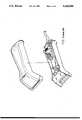
- FIG. 1is an exploded view of the outer shell assembly of a scanner according to the prior art, showing that the component parts of the scanner are mounted on the bottom shell thereof;
- FIG. 2is an exploded view of the preferred embodiment of the present invention (the upper shell is not included);
- FIG. 3is an elevational view of the upper shell
- FIG. 4is an elevational view of a scanner according to the present invention.
- a scanneris generally comprised of an upper shell 1, a bottom shell 2, an intermediate plate 3, two printed circuit boards 4,5, and a LED assembly 6.
- the upper shell 1comprises a plurality of bolt holes 11 spaced on the inside, a plurality of side notches 12 that vary in size.
- the bottom shell 2comprises a plurality of bolt holes 21 respectively connected to the bolt holes 11 of the upper shell 1 by screws 7, a plurality of side notches 22 corresponding to the side notches 12 on the upper shell 1, a plurality of chambers 23 internally disposed at two opposite sides to hold function switches 8 permitting them to be respectively extended out of the side notches 12,22 for operation, a front roller 24 transversely disposed on the inside at the front, a rear roller 25 transversely disposed on the inside at the back, a gear 26 coupled to the front roller 24 at one end, a gear set 27 engaged with the gear 26.
- the printed circuit boards 4,5are fastened inside the bottom shell 2.
- the LED assembly 6is mounted on the bottom shell 2 in front of the front roller 24.
- the intermediate plate 3comprises a fixed scanning lens assembly 31, which has a bolt hole 311 on the rear end thereof to which the first printed circuit board 4 is connected, and a reflector 33 on the front end thereof.
- the first printed circuit board 4is connected to the second printed circuit board by a flat cable 32.
- the upper and bottom shells 1,2are connected together with the intermediate plate 3 secured in therebetween. Because the lens assembly 31 and the reflector 33 are mounted on the intermediate plate 3, and the LED assembly 6 is stopped against the intermediate plate 3, the lens assembly 31, the reflector 33 and the LED assembly 6 will not be caused to displace when the upper and bottom shells 1,2 are forced to deform or crack, and therefore high scanning quality can still be achieved.
Landscapes
- Engineering & Computer Science (AREA)
- Multimedia (AREA)
- Signal Processing (AREA)
- Facsimile Scanning Arrangements (AREA)
Abstract
Description
The present invention relates to scanners, and more particularly, the present invention relates to a scanner mounting hardware which ensures that the scanning lens assembly, the reflector and the LED assembly are retained in place when the outer shell is squeezed to deform.
FIG. 1 illustrates a scanner mounting hardware according to the prior art, in which the scanning lens assembly, the reflector and the LED assembly and other component parts are directly mounted on the bottom shell thereof. When in use, the outer shell assembly may be squeezed to deform easily. Because the major parts of the scanner are directly mounted on the bottom shell of the outer shell assembly, deforming the outer shell assembly of the scanner may cause the scanning lens assembly, the reflector and the LED assembly to displace. Although the displacement is minor, the problem of scanning distortion still happens. Therefore, the position of the scanning lens assembly shall be frequently corrected. However, adjusting the position of the scanning lens assembly is not easy, and shall be made by a skilled person.
The present invention has been accomplished to eliminate the aforesaid problems. It is therefore the main object of the present invention to provide a scanner which can firmly retain the scanning lens assembly, the reflector and the LED assembly thereof in place when the outer shell assembly of the scanner is squeezed to deform. According to the present invention, the scanning lens assembly and the reflector are mounted on an intermediate plate held in between the upper shell and the bottom shell of the outer shell assembly thereof, and the LED assembly is supported on the intermediate plate at the front edge thereof, and therefore the scanning lens assembly, the reflector and the LED assembly are still firmly retained in place when the outer shell assembly of the scanner has been squeezed to deform.
FIG. 1 is an exploded view of the outer shell assembly of a scanner according to the prior art, showing that the component parts of the scanner are mounted on the bottom shell thereof;
FIG. 2 is an exploded view of the preferred embodiment of the present invention (the upper shell is not included);
FIG. 3 is an elevational view of the upper shell; and
FIG. 4 is an elevational view of a scanner according to the present invention.
Referring to FIGS. 2, 3 and 4, a scanner is generally comprised of an upper shell 1, a bottom shell 2, an intermediate plate 3, two printed circuit boards 4,5, and aLED assembly 6. The upper shell 1 comprises a plurality of bolt holes 11 spaced on the inside, a plurality ofside notches 12 that vary in size. The bottom shell 2 comprises a plurality ofbolt holes 21 respectively connected to the bolt holes 11 of the upper shell 1 by screws 7, a plurality ofside notches 22 corresponding to theside notches 12 on the upper shell 1, a plurality ofchambers 23 internally disposed at two opposite sides to hold function switches 8 permitting them to be respectively extended out of theside notches front roller 24 transversely disposed on the inside at the front, arear roller 25 transversely disposed on the inside at the back, agear 26 coupled to thefront roller 24 at one end, a gear set 27 engaged with thegear 26. The printed circuit boards 4,5 are fastened inside the bottom shell 2. TheLED assembly 6 is mounted on the bottom shell 2 in front of thefront roller 24. The intermediate plate 3 comprises a fixed scanning lens assembly 31, which has abolt hole 311 on the rear end thereof to which the first printed circuit board 4 is connected, and areflector 33 on the front end thereof. The first printed circuit board 4 is connected to the second printed circuit board by a flat cable 32.
By threading screws 7 into thebolt holes 11, 21, the upper and bottom shells 1,2 are connected together with the intermediate plate 3 secured in therebetween. Because the lens assembly 31 and thereflector 33 are mounted on the intermediate plate 3, and theLED assembly 6 is stopped against the intermediate plate 3, the lens assembly 31, thereflector 33 and theLED assembly 6 will not be caused to displace when the upper and bottom shells 1,2 are forced to deform or crack, and therefore high scanning quality can still be achieved.
Claims (1)
1. A scanner comprising
an upper shell and a lower shell interconnected to form the body of said scanner, said scanner having a front and a back;
a plurality of circuit boards disposed within said body; and
an intermediate plate disposed within said scanner between said upper and lower shells, said plate having a front edge spaced away from the front of said scanner;
a scanning lens assembly and a reflector mounted on said intermediate plate, an LED assembly mounted in the lower shell at the front of said scanner and abutting the front edge of said intermediate plate whereby said scanning lens, reflector and LED assembly are stabilized within said body by said intermediate plate.
Priority Applications (1)
| Application Number | Priority Date | Filing Date | Title |
|---|---|---|---|
| US07/876,161US5264956A (en) | 1992-04-30 | 1992-04-30 | Scanner mounting hardware |
Applications Claiming Priority (1)
| Application Number | Priority Date | Filing Date | Title |
|---|---|---|---|
| US07/876,161US5264956A (en) | 1992-04-30 | 1992-04-30 | Scanner mounting hardware |
Publications (1)
| Publication Number | Publication Date |
|---|---|
| US5264956Atrue US5264956A (en) | 1993-11-23 |
Family
ID=25367111
Family Applications (1)
| Application Number | Title | Priority Date | Filing Date |
|---|---|---|---|
| US07/876,161Expired - Fee RelatedUS5264956A (en) | 1992-04-30 | 1992-04-30 | Scanner mounting hardware |
Country Status (1)
| Country | Link |
|---|---|
| US (1) | US5264956A (en) |
Cited By (20)
| Publication number | Priority date | Publication date | Assignee | Title |
|---|---|---|---|---|
| US5484994A (en)* | 1993-10-18 | 1996-01-16 | Roustaei; Alexander | Optical scanning head with improved resolution |
| US5543609A (en)* | 1994-10-28 | 1996-08-06 | Symbol Technologies, Inc. | Arrangement for and method of providing shock protection and vibration isolation for a scan module |
| US5588621A (en)* | 1995-02-23 | 1996-12-31 | At&T Global Information Solutions Company | Universal mounting apparatus and method for bar code scanners |
| USD392282S (en) | 1996-09-06 | 1998-03-17 | Hand Held Products, Inc. | Contoured housing for a hand held terminal |
| US5756981A (en)* | 1992-02-27 | 1998-05-26 | Symbol Technologies, Inc. | Optical scanner for reading and decoding one- and-two-dimensional symbologies at variable depths of field including memory efficient high speed image processing means and high accuracy image analysis means |
| US5786582A (en)* | 1992-02-27 | 1998-07-28 | Symbol Technologies, Inc. | Optical scanner for reading and decoding one- and two-dimensional symbologies at variable depths of field |
| US5801918A (en)* | 1996-07-12 | 1998-09-01 | Hand Held Products, Inc. | Ergonomic housing for a micro computer |
| USD400872S (en) | 1997-10-27 | 1998-11-10 | Hand Held Products, Inc. | Contoured housing |
| US5838540A (en)* | 1997-04-09 | 1998-11-17 | Wen-Shyong; Chang | Scanner casing |
| US5850078A (en)* | 1996-01-16 | 1998-12-15 | Symbol Technologies, Inc. | Simplified assembly and automatic testing of components in electro-optical systems for reading coded indicia |
| USD405076S (en)* | 1996-03-19 | 1999-02-02 | Hand Held Products, Inc. | Hand held optical scanner |
| USD405075S (en)* | 1996-03-18 | 1999-02-02 | Hand Held Products, Inc. | Housing for hand held optical scanner |
| USD439898S1 (en) | 1996-03-18 | 2001-04-03 | Hand Held Products, Inc. | Contoured housing |
| US6305676B1 (en)* | 1999-11-24 | 2001-10-23 | Silitek Corporation | Buckling device of a scanner head |
| USD473872S1 (en) | 1996-03-18 | 2003-04-29 | Hand Held Products, Inc. | Contoured housing |
| USD476330S1 (en) | 1996-03-18 | 2003-06-24 | Hand Held Products, Inc. | Contoured housing |
| USD492681S1 (en) | 1996-03-18 | 2004-07-06 | Hand Held Products, Inc. | Contoured housing |
| USD505423S1 (en) | 1996-03-18 | 2005-05-24 | Hand Held Products, Inc. | Finger saddle incorporated in cornerless housing |
| US20060054704A1 (en)* | 2004-09-10 | 2006-03-16 | Fitch Timothy R | Hand held computer device |
| USD599798S1 (en) | 2004-09-10 | 2009-09-08 | Hand Held Products, Inc. | Hand held computer device |
Citations (5)
| Publication number | Priority date | Publication date | Assignee | Title |
|---|---|---|---|---|
| US4387297A (en)* | 1980-02-29 | 1983-06-07 | Symbol Technologies, Inc. | Portable laser scanning system and scanning methods |
| US4748319A (en)* | 1985-10-08 | 1988-05-31 | Alps Electric Co., Ltd. | Bar code scanner |
| US4896026A (en)* | 1988-10-31 | 1990-01-23 | Symbol Technologies, Inc. | Laser diode scanner with improved shock mounting |
| US5015833A (en)* | 1988-10-31 | 1991-05-14 | Symbol Technologies, Inc. | Scan board module for laser scanners |
| US5081343A (en)* | 1981-12-28 | 1992-01-14 | Norand Corporation | Instant portable bar code reader |
- 1992
- 1992-04-30USUS07/876,161patent/US5264956A/ennot_activeExpired - Fee Related
Patent Citations (6)
| Publication number | Priority date | Publication date | Assignee | Title |
|---|---|---|---|---|
| US4387297A (en)* | 1980-02-29 | 1983-06-07 | Symbol Technologies, Inc. | Portable laser scanning system and scanning methods |
| US4387297B1 (en)* | 1980-02-29 | 1995-09-12 | Symbol Technologies Inc | Portable laser scanning system and scanning methods |
| US5081343A (en)* | 1981-12-28 | 1992-01-14 | Norand Corporation | Instant portable bar code reader |
| US4748319A (en)* | 1985-10-08 | 1988-05-31 | Alps Electric Co., Ltd. | Bar code scanner |
| US4896026A (en)* | 1988-10-31 | 1990-01-23 | Symbol Technologies, Inc. | Laser diode scanner with improved shock mounting |
| US5015833A (en)* | 1988-10-31 | 1991-05-14 | Symbol Technologies, Inc. | Scan board module for laser scanners |
Cited By (22)
| Publication number | Priority date | Publication date | Assignee | Title |
|---|---|---|---|---|
| US5756981A (en)* | 1992-02-27 | 1998-05-26 | Symbol Technologies, Inc. | Optical scanner for reading and decoding one- and-two-dimensional symbologies at variable depths of field including memory efficient high speed image processing means and high accuracy image analysis means |
| US5786582A (en)* | 1992-02-27 | 1998-07-28 | Symbol Technologies, Inc. | Optical scanner for reading and decoding one- and two-dimensional symbologies at variable depths of field |
| US5484994A (en)* | 1993-10-18 | 1996-01-16 | Roustaei; Alexander | Optical scanning head with improved resolution |
| US5543609A (en)* | 1994-10-28 | 1996-08-06 | Symbol Technologies, Inc. | Arrangement for and method of providing shock protection and vibration isolation for a scan module |
| US5588621A (en)* | 1995-02-23 | 1996-12-31 | At&T Global Information Solutions Company | Universal mounting apparatus and method for bar code scanners |
| US5850078A (en)* | 1996-01-16 | 1998-12-15 | Symbol Technologies, Inc. | Simplified assembly and automatic testing of components in electro-optical systems for reading coded indicia |
| USD473872S1 (en) | 1996-03-18 | 2003-04-29 | Hand Held Products, Inc. | Contoured housing |
| USD456806S1 (en) | 1996-03-18 | 2002-05-07 | Hand Held Products, Inc. | Contoured housing |
| USD505423S1 (en) | 1996-03-18 | 2005-05-24 | Hand Held Products, Inc. | Finger saddle incorporated in cornerless housing |
| USD492681S1 (en) | 1996-03-18 | 2004-07-06 | Hand Held Products, Inc. | Contoured housing |
| USD476330S1 (en) | 1996-03-18 | 2003-06-24 | Hand Held Products, Inc. | Contoured housing |
| USD405075S (en)* | 1996-03-18 | 1999-02-02 | Hand Held Products, Inc. | Housing for hand held optical scanner |
| USD439898S1 (en) | 1996-03-18 | 2001-04-03 | Hand Held Products, Inc. | Contoured housing |
| USD405076S (en)* | 1996-03-19 | 1999-02-02 | Hand Held Products, Inc. | Hand held optical scanner |
| US5801918A (en)* | 1996-07-12 | 1998-09-01 | Hand Held Products, Inc. | Ergonomic housing for a micro computer |
| USD392282S (en) | 1996-09-06 | 1998-03-17 | Hand Held Products, Inc. | Contoured housing for a hand held terminal |
| US5838540A (en)* | 1997-04-09 | 1998-11-17 | Wen-Shyong; Chang | Scanner casing |
| USD400872S (en) | 1997-10-27 | 1998-11-10 | Hand Held Products, Inc. | Contoured housing |
| US6305676B1 (en)* | 1999-11-24 | 2001-10-23 | Silitek Corporation | Buckling device of a scanner head |
| US20060054704A1 (en)* | 2004-09-10 | 2006-03-16 | Fitch Timothy R | Hand held computer device |
| US7446753B2 (en) | 2004-09-10 | 2008-11-04 | Hand Held Products, Inc. | Hand held computer device |
| USD599798S1 (en) | 2004-09-10 | 2009-09-08 | Hand Held Products, Inc. | Hand held computer device |
Similar Documents
| Publication | Publication Date | Title |
|---|---|---|
| US5264956A (en) | Scanner mounting hardware | |
| US6480245B1 (en) | LCD in which lamp reflector is grounded to panel housing via screw, pinch fastening, or snap pressing means | |
| USD365808S (en) | Video circuit board housing associated with a multi-media terminal | |
| USD424020S (en) | Electrical connector | |
| USD356098S (en) | Electronic still camera with printer | |
| USD319998S (en) | Housing for an electrical connector | |
| USD278143S (en) | Printed circuit board standoff | |
| CA2083017A1 (en) | Tandem Circuit Cards | |
| USD348247S (en) | Electronic circuit housing | |
| USD361751S (en) | Strain relief for electrical connectors | |
| USD281687S (en) | Telephone set | |
| USD342952S (en) | Antenna mounting clamp | |
| USD408013S (en) | Connection module for a PCB (printed circuit board) | |
| KR970014271A (en) | Cabinet of monitor device | |
| US6084192A (en) | Slide knob mounting structure | |
| USD409147S (en) | Connection module for a PCB | |
| USD340720S (en) | Antenna mounting clamp | |
| USD492575S1 (en) | Printed circuit board daughter board support | |
| US6116950A (en) | Stand-off for memory card connector | |
| USD354042S (en) | Housing for a plug-in printed circuit board | |
| US7324155B2 (en) | Camera case structure for a mobile communication device | |
| USD349886S (en) | Socket for mounting a printed circuit board module | |
| CA2024047A1 (en) | Display tube assembly and mounting process thereof | |
| USD342951S (en) | Antenna mounting clamp | |
| USD342950S (en) | Antenna mounting clamp |
Legal Events
| Date | Code | Title | Description |
|---|---|---|---|
| AS | Assignment | Owner name:SILITEK CORPORATION, TAIWAN Free format text:ASSIGNMENT OF ASSIGNORS INTEREST.;ASSIGNOR:TZU-CHIN, HUANG;REEL/FRAME:006117/0898 Effective date:19920402 | |
| FPAY | Fee payment | Year of fee payment:4 | |
| REMI | Maintenance fee reminder mailed | ||
| FP | Lapsed due to failure to pay maintenance fee | Effective date:19971126 | |
| FEPP | Fee payment procedure | Free format text:PAYOR NUMBER ASSIGNED (ORIGINAL EVENT CODE: ASPN); ENTITY STATUS OF PATENT OWNER: LARGE ENTITY Free format text:PAT HLDR NO LONGER CLAIMS SMALL ENT STAT AS INDIV INVENTOR (ORIGINAL EVENT CODE: LSM1); ENTITY STATUS OF PATENT OWNER: LARGE ENTITY | |
| FPAY | Fee payment | Year of fee payment:8 | |
| REMI | Maintenance fee reminder mailed | ||
| LAPS | Lapse for failure to pay maintenance fees | ||
| LAPS | Lapse for failure to pay maintenance fees | Free format text:PATENT EXPIRED FOR FAILURE TO PAY MAINTENANCE FEES (ORIGINAL EVENT CODE: EXP.); ENTITY STATUS OF PATENT OWNER: LARGE ENTITY | |
| STCH | Information on status: patent discontinuation | Free format text:PATENT EXPIRED DUE TO NONPAYMENT OF MAINTENANCE FEES UNDER 37 CFR 1.362 | |
| FP | Lapsed due to failure to pay maintenance fee | Effective date:20051123 |