US5264118A - Pipeline conditioning process for mined oil-sand - Google Patents
Pipeline conditioning process for mined oil-sandDownload PDFInfo
- Publication number
- US5264118A US5264118AUS07/812,920US81292091AUS5264118AUS 5264118 AUS5264118 AUS 5264118AUS 81292091 AUS81292091 AUS 81292091AUS 5264118 AUS5264118 AUS 5264118A
- Authority
- US
- United States
- Prior art keywords
- bitumen
- slurry
- oil sand
- pipeline
- water
- Prior art date
- Legal status (The legal status is an assumption and is not a legal conclusion. Google has not performed a legal analysis and makes no representation as to the accuracy of the status listed.)
- Expired - Fee Related
Links
- 239000003027oil sandSubstances0.000titleclaimsabstractdescription91
- 230000003750conditioning effectEffects0.000titleclaimsdescription29
- 238000000034methodMethods0.000titleclaimsdescription28
- 230000008569processEffects0.000titleclaimsdescription25
- 239000002002slurrySubstances0.000claimsabstractdescription114
- 239000010426asphaltSubstances0.000claimsabstractdescription112
- 238000000926separation methodMethods0.000claimsabstractdescription47
- XLYOFNOQVPJJNP-UHFFFAOYSA-NwaterSubstancesOXLYOFNOQVPJJNP-UHFFFAOYSA-N0.000claimsabstractdescription39
- 230000005484gravityEffects0.000claimsabstractdescription16
- 238000005273aerationMethods0.000claimsabstractdescription5
- 238000011084recoveryMethods0.000claimsdescription53
- 239000007787solidSubstances0.000claimsdescription28
- 238000005188flotationMethods0.000claimsdescription18
- 238000000605extractionMethods0.000claimsdescription17
- 239000000203mixtureSubstances0.000claimsdescription14
- 239000004614Process AidSubstances0.000claimsdescription13
- 238000012545processingMethods0.000claimsdescription8
- 239000004576sandSubstances0.000claimsdescription8
- 239000012530fluidSubstances0.000claimsdescription7
- 238000005086pumpingMethods0.000claimsdescription7
- 238000005065miningMethods0.000claimsdescription5
- 238000012216screeningMethods0.000claimsdescription3
- HEMHJVSKTPXQMS-UHFFFAOYSA-MSodium hydroxideChemical compound[OH-].[Na+]HEMHJVSKTPXQMS-UHFFFAOYSA-M0.000abstractdescription24
- 230000000717retained effectEffects0.000abstractdescription3
- 238000004581coalescenceMethods0.000abstract1
- 239000003921oilSubstances0.000description17
- 238000012360testing methodMethods0.000description9
- 230000002269spontaneous effectEffects0.000description7
- 239000003518causticsSubstances0.000description6
- 230000001143conditioned effectEffects0.000description6
- 230000014759maintenance of locationEffects0.000description5
- 238000004458analytical methodMethods0.000description4
- 238000007792additionMethods0.000description3
- 230000000694effectsEffects0.000description3
- 239000000463materialSubstances0.000description3
- 239000008161low-grade oilSubstances0.000description2
- 238000011160researchMethods0.000description2
- 239000011435rockSubstances0.000description2
- 239000000243solutionSubstances0.000description2
- 230000035899viabilityEffects0.000description2
- 238000000944Soxhlet extractionMethods0.000description1
- 239000008346aqueous phaseSubstances0.000description1
- 230000008859changeEffects0.000description1
- 239000000356contaminantSubstances0.000description1
- -1cyclofeeder rejectsSubstances0.000description1
- 238000011161developmentMethods0.000description1
- 239000012470diluted sampleSubstances0.000description1
- 238000010790dilutionMethods0.000description1
- 239000012895dilutionSubstances0.000description1
- 238000006073displacement reactionMethods0.000description1
- 238000004945emulsificationMethods0.000description1
- 238000005516engineering processMethods0.000description1
- 230000003628erosive effectEffects0.000description1
- 239000013505freshwaterSubstances0.000description1
- 238000010438heat treatmentMethods0.000description1
- 238000012986modificationMethods0.000description1
- 230000004048modificationEffects0.000description1
- JTJMJGYZQZDUJJ-UHFFFAOYSA-NphencyclidineChemical classC1CCCCN1C1(C=2C=CC=CC=2)CCCCC1JTJMJGYZQZDUJJ-UHFFFAOYSA-N0.000description1
- 230000000135prohibitive effectEffects0.000description1
- 239000011369resultant mixtureSubstances0.000description1
- 230000000630rising effectEffects0.000description1
- 239000000523sampleSubstances0.000description1
- 239000000725suspensionSubstances0.000description1
- 230000032258transportEffects0.000description1
- 238000005406washingMethods0.000description1
- 238000003809water extractionMethods0.000description1
- 238000005303weighingMethods0.000description1
Images


Classifications
- C—CHEMISTRY; METALLURGY
- C10—PETROLEUM, GAS OR COKE INDUSTRIES; TECHNICAL GASES CONTAINING CARBON MONOXIDE; FUELS; LUBRICANTS; PEAT
- C10G—CRACKING HYDROCARBON OILS; PRODUCTION OF LIQUID HYDROCARBON MIXTURES, e.g. BY DESTRUCTIVE HYDROGENATION, OLIGOMERISATION, POLYMERISATION; RECOVERY OF HYDROCARBON OILS FROM OIL-SHALE, OIL-SAND, OR GASES; REFINING MIXTURES MAINLY CONSISTING OF HYDROCARBONS; REFORMING OF NAPHTHA; MINERAL WAXES
- C10G1/00—Production of liquid hydrocarbon mixtures from oil-shale, oil-sand, or non-melting solid carbonaceous or similar materials, e.g. wood, coal
- C10G1/04—Production of liquid hydrocarbon mixtures from oil-shale, oil-sand, or non-melting solid carbonaceous or similar materials, e.g. wood, coal by extraction
- C10G1/045—Separation of insoluble materials
- C—CHEMISTRY; METALLURGY
- C10—PETROLEUM, GAS OR COKE INDUSTRIES; TECHNICAL GASES CONTAINING CARBON MONOXIDE; FUELS; LUBRICANTS; PEAT
- C10G—CRACKING HYDROCARBON OILS; PRODUCTION OF LIQUID HYDROCARBON MIXTURES, e.g. BY DESTRUCTIVE HYDROGENATION, OLIGOMERISATION, POLYMERISATION; RECOVERY OF HYDROCARBON OILS FROM OIL-SHALE, OIL-SAND, OR GASES; REFINING MIXTURES MAINLY CONSISTING OF HYDROCARBONS; REFORMING OF NAPHTHA; MINERAL WAXES
- C10G1/00—Production of liquid hydrocarbon mixtures from oil-shale, oil-sand, or non-melting solid carbonaceous or similar materials, e.g. wood, coal
- C10G1/04—Production of liquid hydrocarbon mixtures from oil-shale, oil-sand, or non-melting solid carbonaceous or similar materials, e.g. wood, coal by extraction
- C10G1/047—Hot water or cold water extraction processes
Definitions
- This inventionrelates to simultaneously transporting and conditioning oil sand in an aqueous slurry in a pipeline extending between a mine and an extraction plant. More particularly, it relates to a process comprising the steps of forming a slurry comprising oil sand, hot water, entrained air and (optionally) process aid (e.g. NaOH) at the mine site, pumping the resultant slurry through the pipeline, whereby contained bitumen flecks coalesce and are aerated, and feeding the slurry directly into a gravity separation vessel to recover the major portion of the bitumen as primary froth.
- process aide.g. NaOH
- the present inventionis a modification of the conventional commercial system used to extract bitumen from mineable oil sand.
- the present inventionis a modification of the conventional commercial system used to extract bitumen from mineable oil sand.
- oil sandspecifically the oil sand of the Athabasca deposit which exists in Northern Alberta.
- This oil sandcomprises sand grains that are water-wet or individually coated with a thin sheath of water.
- the bitumen or oilis present as flecks located in the interstices between the wet grains.
- the depositis surface mined by first removing overburden and then using a dragline to excavate the oil sand and dump it to one side in the form of a windrow.
- a bucket wheel reclaimertransfers this windrowed oil sand on to the feed end of a conveyor belt train, which carries it to an extraction plant.
- Applicant's operationinvolves mining about 300,000 tons of oil sand per day in this way.
- Four draglinesare employed, each feeding a separate reclaimer and conveyor belt train.
- Each such conveyor belt traincomprises a plurality of separate endless conveyors placed end to end in series.
- the conveyors of one traintypically can extend a length of 5 miles.
- the conveyor system being utilizedis characterized by a number of disadvantages, including:
- a 72 inch wide conveyor having a length of 3 milesrequires several 1200 horsepower motors for operation;
- tacky bitumencauses some oil sand to adhere to and build up on the belt surface. This creates a dead load which is difficult to prevent and remove;
- the conveyor systems usedare a troublesome and expensive means for transferring the oil sand from the mine to the extraction plant.
- a conveyor systemtransports the whole oil sand to the plant, for the sole purpose of extracting the bitumen.
- the bitumenconstitutes only about 6-15% by weight of the processable oil sand mass. Conveying all of the associated gangue material significantly reduces the economic attractiveness of the operation.
- each drumis 30.5 m long and 5.5 m in diameter.
- Each such drumis fed about 4500 tph of oil sand, 1100 tph of hot water (95° C.) and 5 tph of aqueous 10% caustic solution. Steam is injected into the slurry, as required, to ensure a final slurry temperature of about 80° C. The retention time in the drum is about 3 minutes.
- bitumen flecksby contacting them with air bubbles, whereby the bitumen coats the air bubbles.
- conditioningused in the industry to identify the sum total of these various actions, is “conditioning" the slurry.
- a definitionis given below with respect to when conditioning is “complete” for the purposes of this invention.
- the slurryAfter being conditioned in the tumbler, the slurry is screened, to reject oversize, and simultaneously is diluted with additional hot water to produce a slurry having about 50% solids by mass (based on the initial oil sand feed).
- the screened, diluted slurryis fed into a large, thickener-like vessel referred to as a gravity separation vessel or primary separation vessel (or "PSV").
- PSDgravity separation vessel
- the vesselis open-topped, having a cylindrical upper section and a conical lower section equipped with a bottom outlet.
- the diluted slurryis temporarily retained in the PSV for about 45 minutes in a quiescent state.
- the coarse solids sink(having a density of about 2.65), are concentrated in the cone, and exit through the bottom outlet as a fairly dense tailings stream.
- the non-aerated bitumen fleckshave a density of about 1.0 and thus have little natural tendency to rise. However, the bitumen has an affinity for air.
- bitumen frothThe process conducted in the PSV may be referred to as involving "spontaneous flotation".
- the watery suspension remaining in the central portion of the PSVcontains some residual bitumen. Much of this bitumen was not sufficiently aerated so as to be recovered as primary froth from the PSV. Therefore it is necessary to further process this fluid to recover the remaining bitumen. This is done by means of vigorously sub-aerating and agitating the fluid in one or more secondary recovery vessels. For example, a dragstream of the middlings from the PSV may be fed to a series of sub-aerated flotation cells. A yield of bitumen froth, termed secondary froth, is recovered. Flotation in the PSV may be referred to as "spontaneous flotation" while flotation in the secondary recovery vessels may be referred to as "forced air flotation".
- the primary bitumen frothis formed under quiescent condition and hence has less entrainment of gangue material. Thus it is considerably "cleaner" than secondary froth, in that it contains less water and solids contaminants. So it is desirable to produce the bitumen in the form of primary froth, to the greatest extent possible.
- bitumenis predominantly recovered in the form of primary froth.
- oil sandis of "poor" grade (i.e. low in bitumen content (e.g. 8%) and high in fines content (e.g. 30%), it will process relatively poorly, giving:
- the conventional extraction circuitcomprises a tumbling step that is designed to condition the slurry. Tumbling is followed by a sequence of spontaneous and forced air flotation steps. If conditioning is properly conducted, the total bitumen recovery and bitumen loss values for different grades of feed will approximate those illustrative values just given.
- particulate solidsmay be slurried in water and conveyed by pumping them through a pipeline, as an alternative to using conveyor belt systems.
- the present inventionarose from an experimental project directed toward investigating pipeline conveying of oil sands in aqueous slurry form.
- bitumenwould become excessively emulsified in the course of being pumped a long distance through a pipeline, so that the bitumen would become difficult to recover from the slurry.
- the present inventionis based on having made certain experimental discoveries, namely:
- a slurrycomprising oil sand, water and process aid, is formed so as to entrain air bubbles and is pumped through a pipeline a distance in the order of about 2.5 km (which is commonly less than the distance between the surface mine and the extraction plant), complete conditioning of the slurry is achieved. More particularly, a sufficient quantity of the contained bitumen becomes aerated and is rendered buoyant.
- the slurrymay be introduced directly into the PSV of a conventional separation circuit, in which PSV spontaneous flotation takes place to yield total recovery, underflow loss, and froth quality values that are comparable to those obtained by a conventional extraction train involving a tumbler and separation circuit;
- That the slurrymay be at a relatively low temperature (e.g. in the order of 50° C.) and yet conditioning may still be successfully completed as aforesaid;
- the breakover point indicators when conditioningis "complete". Such complete conditioning of the slurry is reflected in the total recovery and tailings loss values resulting from subsequent processing of the slurry in a conventional separation circuit. More particularly, the total recovery of bitumen will exceed 90% by weight and the tailings loss of bitumen will be less than 10%, with respect to a feed of sufficient quality to be acceptable for a conventional extraction circuit. Preferably the total recovery of bitumen and bitumen losses for good and poor grade oil sands will be of the order of those values previously stated;
- the oil sand oversizeis removed, by crushing or screening, prior to mixing, to reduce lumps to a size less than about 1/3 of the internal diameter of the pipeline. If the lumps are too large, plugging of the line can ensue.
- the oil sandis mixed at the mine site with hot water typically at 95° C.) and, preferably, alkaline process aid (usually sodium hydroxide), in a manner whereby air bubbles are entrained, to form an aerated slurry having a composition and temperature falling within the following preferred ranges:
- alkaline process aidusually sodium hydroxide
- the slurryis then pumped through a pipeline from the mine site to an extraction plant.
- the pipelinemust be of sufficient length so that substantially complete conditioning of the oil sand occurs.
- the slurryis moved through a first section of the pipeline, in which substantially complete conditioning is accomplished, and then separation of substantially all of the coarse solids (i.e. greater than 200 mesh) is effected at this point. This may be accomplished by gravity or enhanced settling, such as with cyclones. Depending on the density of the slurry, dilution with water may be required for good separation.
- the remaining slurryis then pumped through a second section of the pipeline to the extraction plant. On reaching the extraction plant, the slurry is introduced directly into a conventional separation circuit comprising spontaneous and forced air flotation units.
- the inventionis a process for simultaneously transporting and conditioning naturally water-wet oil sand to enable recovery of bitumen in a conventional gravity separation vessel, comprising: surface mining oil sand at a mine site; mixing the oil sand, at the mine site, with hot water and process aid, if required, and entraining air in the fluid during mixing to form an aerated slurry; pumping the slurry through a pipeline from the mine site to a bitumen extraction plant, said pipeline being of sufficient length so that separation of bitumen from sand and subsequent aeration of the bitumen both occur, to render the aerated bitumen buoyant; and introducing the slurry from the pipeline directly into a gravity separation vessel and processing it therein by gravity separation under quiescent conditions to recover bitumen in the form of froth.
- FIG. 1is a schematic of the laboratory circuit used in connection with development of the invention
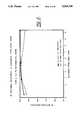
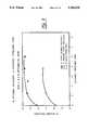
- FIG. 2is a plot showing bitumen recovery variation with distance pipelined, for a 13.2% bitumen-containing oil sand treated in the laboratory circuit of FIG. 1;
- FIG. 3is a plot showing bitumen recovery variation with distance pipelined, for a 9.2% bitumen-containing oil sand treated in the laboratory circuit of FIG. 1;
- FIG. 4is a plot showing the variation in bitumen lost with the tails with distance pipelined for a 9.2% bitumen-containing oil sand treated in the laboratory circuit of FIG. 1;
- FIG. 5is a plot showing the variation in percent of bitumen not amenable to flotation with distance pipelined for a 9.2% bitumen-containing oil sand treated in the laboratory circuit of FIG. 1;
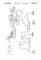
- FIG. 6is a schematic of an industrial scale system for practising the process
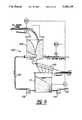
- FIG. 7is a schematic showing the invention in the context of operating between the mine site and a bitumen extraction plant comprising primary and secondary separation;
- FIG. 8is a schematic showing the 4 inch pipeline pilot
- FIG. 9is a schematic showing the cyclofeeder used in the pilot of FIG. 8;
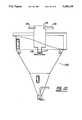
- FIG. 10is a side sectional view of the primary separation vessel (PSV) used in the pilot of FIG. 8;
- FIG. 11is a plot of bitumen recovery versus distance pipelined for the Auxiliary Pit "A" oil sand;
- FIG. 12is a plot of froth composition versus distance pipelined for the Auxiliary Pit "A" oil sand;
- FIG. 13is a plot of bitumen recovery versus distance pipelined for the Auxiliary Pit “B” oil sand:
- FIG. 14is a plot of froth composition versus distance pipelined for the Auxiliary Pit "B" oil sand;
- FIG. 14is a plot of bitumen recovery versus distance pipelined for the Base Mine "A" oil sand.
- FIG. 16is a plot of froth composition versus distance pipelined for the Base Mine "A" oil sand.
- FIG. 1The loop 1 was 230 feet long and had an internal diameter of 2 inches.
- the loop 1was connected with a pump box 2. Oil sand could be fed to the pump box 2 by a conveyor 3.
- a positive displacement pump 4was connected to the bottom outlet of the box 2. Slurry could be re-circulated back into the pump box 2 from the initial section of the loop 1 via a pipe leg 5.
- Valves 6,7controlled the leg 5 and loop 1 (downstream of the leg 5) respectively.
- the pump box 2would be filled with an amount of water in excess over that required to fill loop 1. Valve 6 would be opened and valve 7 closed.
- Oil sandwould then be fed into the pump box 2 and the mixture circulated through the box 2 tangentially to entrain air and form an aerated slurry.
- sodium hydroxidein the form of a 10% solution, was added at the pump box; in other runs, no sodium hydroxide was added. Recirculation was continued for 30 seconds, to form the slurry. After such circulation, the valve 7 was opened and the valve 6 closed, so that the full loop 1 was now in use. Circulation through the full loop would then be continued for the retention time required to establish the pipeline distance to be travelled by the slurry.
- slurry withdrawn from the loop 1was tested in a laboratory scale separation circuit. More particularly, withdrawn samples were treated as follows:
- a slurry sample of 300 mLwas collected in a 1 L jar already containing 300 mL of water having a temperature of 50° C. (so that the resultant mixture now corresponded in water content with that of the diluted slurry conventionally fed to a primary separation vessel), and stirred;
- the diluted samplewas settled for 1 minute under quiescent conditions, to allow froth to rise by spontaneous flotation and solids to settle;
- the froth(which was the "primary” froth) was skimmed off and analyzed for bitumen, water and solids;
- the aqueous layerwas decanted off and saved;
- the coarse solidswere washed with 150 ml of 50° C. water by capping the jar and rotating it gently 5 times. After settling for 1 minute, the aqueous phase was decanted and saved. This washing procedure was repeated twice more;
- the washed solidswere analyzed for oil, water and solids
- the water decant fractionswere combined.
- the productwas subjected to induced air flotation at an impeller speed of 800 rpm and air rate of 50 mL/minute.
- the temperature of the chargewas maintained at 50° C. and air addition was continued for 5 minutes.
- Secondary frothwas produced and collected. This secondary froth and the residual tailings were analyzed for bitumen, water and solids.
- That conditioningis complete within a short distance travelled, said distance being substantially less than the distance between the mine and the plant (for most of the plant life in a typical case);
- That pipelining slurrywill produce primary and total bitumen recoveries as good as or better than those from a conventional tumbler/flotation train;
- the coarse solidsmay be separated without prohibitive bitumen losses
- That processaids are required for low grade oil sand to achieve good recoveries.
- FIG. 6there is schematically shown a recommended system for practising the invention.
- oil sandis surface mined and deposited in a feed bin.
- the oil sandis then fed to a crusher 55 of the double roll type, to reduce the oversize to less than 24".
- the crushed oil sandis fed by conveyor 56 to a mixer 57.
- This mixer 57is shown in FIG. 7. It comprises an open-topped cylindrical vessel 58 having a conical bottom 59 with a central outlet 60.
- a pair of tangential inlets 61, 62extend into the base of the vessel chamber 58.
- Fresh hot water, containing caustic,is fed into chamber 58 via the inlet 61.
- Recycled hot slurryis fed in via inlet 62.
- the oil sandis mixed with the slurry and water and caustic streams, which are circulating in the form of a vortex in the chamber 58, and air bubbles are entrained into the slurry.
- the hot water and caustic additionsare controlled to yield a slurry typically having the following values:
- the recycled slurryis withdrawn from pump box 64 and returned by pump 65 and line 66 to the inlet 62.
- Slurryis pumped by pump 67 from pump box 64 into pipeline 68.
- the slurryis conveyed through a first section of pipeline 68, far enough to completely condition the slurry. The extent of conditioning may be established using laboratory equipment and procedures as previously described. At this point, the slurry is diluted and introduced into a settler 69 and retained under quiescent conditions, to allow the coarse solids to settle. The solids are removed as tailings and discarded.
- the remaining slurryis pumped through a second section 70 of pipeline to a conventional separation circuit 71.
- the slurryis subjected to spontaneous flotation in a primary separation vessel 72 and middlings from the vessel 72 are subjected to forced air flotation in cells 73 to produce primary and secondary froth.
- the slurry temperature(55° C.) is considerably less than the conventional temperature ( ⁇ 80° C.). If a tumbler were to be used with such a "low temperature" slurry, it would have to be very large, to provide a longer retention time. By the combination of conditioning in a pipeline and feeding conditioned slurry directly to the PSV, a low temperature process is now feasible.
- the inventionwas further tested in a larger scale field pilot test of multiple runs, each involving continuous mixing to produce slurry, once-through pipelining at constant velocity through distances between 0 km and 2.5 km, and gravity separation/flotation in a separation vessel.
- FIG. 8The process schematic of the facility used to conduct this test is shown in FIG. 8.
- testinvolved a continuous, once through system which involved a mixer assembly 100, previously described and hereinafter referred to as the cyclofeeder, 2.5 km of 4 inch pipeline 101 and a deep cone primary separation vessel 102.
- the systemoperated at an oil sand feed rate of 100 tonne per hour.
- the testverified that sufficient slurry conditioning could be achieved in a pipeline to enable viable bitumen recovery from subsequent processing in a primary separation vessel.
- the bitumen recoveries and froth bitumen contentswere comparable to those from applicant's conventional hot water extraction plant.
- the recoveriesimproved With the distance pipelined, but levelled off by 2.5 km (a residence time of 14 minutes).
- the solids content in the primary froth from the primary separation vessel (PSV)increased with the distance pipelined and the content was slightly greater than conventional PSV froth.
- a systemcomprising the cyclofeeder 100 and pipeline 101 was shown to be a viable alternative to the conventional equipment comprising conveyors and tumblers.
- the cyclofeeder 100was demonstrated to be a viable means for continuously forming the oil sand slurry. Operation of this unit involved a fast rotating vortex formed in the mixer 103, which vortex was created by partial recirculation of screened slurry. This vortex was utilized to disperse and suspend the stream of oil sand being fed into the mixer 103. The cyclofeeder tested was able to continuously and consistently produce high density oil sand slurries.
- the processing linebegan with a vibrating grizzly scalper 104 having 6 ⁇ 12 inch openings.
- a belt conveyor 105fed the scalper product to a dry screen 106 having 4 ⁇ 4 inch openings.
- the product from the screenwas fed by a belt conveyor 107 to the feeder 108 of a belt conveyor 109.
- the belt conveyor 109fed the oil sand into the mixer 103.
- the assembly so describeddelivered 100 tonnes per hour of oil sand to the mixer 103;
- the cyclofeeder 100involved the mixer 103 (shown in FIG. 8), screen 110, and pump box 111. Slurry was recycled from the pump box 111 to the mixer 100 through the line 112 by a recirculation pump 113. The recycled slurry was jetted tangentially into the mixer 100, as was a stream of fresh water (95° C.) and caustic as required. The recycled slurry (60 dm 3 /S) maintained the vortex in which mixing took place. The mixer 100 discharged onto the vibrating screen 110, which removed the +3/4 inch solids. The product slurry from the screen 110 passed into the pump box 111. Up to 22 dm 3 /S of dense oil sand slurry (1.65 kg/dm 3 ) was generated at temperatures up to 60° C.;
- the slurrywas pumped from the pump box 111 through the pipeline 101 which was formed in five 500 m sections connected by a series of pumps 114.
- the operating length of the pipelinecould be varied in section increments from 0 to 2.5 km. Samples could be taken at intervals along the pipeline;
- the pipeline 101discharged into a mixing well 115 in the upper end of the deep cone primary separation vessel (PSV) 102.
- the entering slurrywas diluted with floodwater (60°) introduced into the mixing well 115 through line 116, to reduce the product density to about 1.50 kg/dm 3 .
- the diluted slurrywas discharged downwardly through outlet 117 and deflected to spread out laterally by plate 118.
- the slurrywas separated into bitumen froth overflow, middlings and coarse tailings underflow.
- the frothflowed into a weighing tank 119.
- the middlings and tailingswere discharged to a disposal pond;
- the three oil sandswere from different locations and were of different composition. Runs were performed for each oil sand at pipeline lengths of 0 km, 1.5 km and 2.5 km. For the first oil sand, an additional series of mass balances was performed at 0.5 km. The velocity of the slurry in the pipeline was held constant at 3 +/-0.3 m/s. The slurry density was held constant at 1.6 +/-0.05 kg/dm 3 and the slurry temperature at 55 +/-5° C.;
- FIG. 11shows the effect of distance pipelined on froth quality of the oil sand from Auxiliary pit A. This oil sand processed well without caustic addition. Even when the slurry was pipelined directly from the cyclofeeder to the PSV, the primary bitumen recoveries averaged 81%. After 0.5 km of travel through the pipeline, both the primary and total recoveries had essentially levelled out, achieving average values of 90% and 94% respectively. Pumping the slurry over greater distance increased the bitumen recovery only slightly. These recoveries compare well with those obtained using the conventional tumbler/PSV circuit in applicants' plant.
- FIG. 12shows the effect of distance pipelined on froth quality for the oil sand from Auxiliary pit A.
- the amount of bitumen in the frothshows no significant change with distance.
- the 67% average bitumen content in primary frothcompares well with the result obtained in the conventional circuit.
- the average amount of solids in the frothincreased from 7.9 up to 12.5 wt % as the distance pipelined increased from 0 km to 2.5 km.
- FIGS. 13 and 14The results of processing the oil sand from Auxiliary Pit “B" are shown in FIGS. 13 and 14. This was a low grade oil sand. The oil sand processed very poorly when sent to the PSV directly from the cyclofeeder, giving average primary and total recoveries of 24% and 42% respectively. As shown in FIG. 13, these recoveries increased significantly as the conditioning time or distance pipelined increased. The total recovery after the full 2.5 km pipelining distance was 89%. As with the first oil sand, the amount of solids in the primary froth increased with distance pipelined. The maximum froth solids level reached was 9.9%, which is comparable to conventional results.
- the last oil sand processedwas from the Base Mine. This was a higher grade oil sand with bitumen content of 11.3 wt. % and fines content of 28.9%. As shown in FIG. 15, at 0 km the slurry produced an average primary recovery of 56% and an average total recovery of 75%. After 1.5 km of pipeline travel, the bitumen primary and total recoveries increased significantly. Increasing the travel by an additional 1 km produced only a slight increase in recoveries. As shown in FIG. 16, the solids content in the primary froth increased with pipeline travel time.
Landscapes
- Chemical & Material Sciences (AREA)
- Engineering & Computer Science (AREA)
- Oil, Petroleum & Natural Gas (AREA)
- Life Sciences & Earth Sciences (AREA)
- Wood Science & Technology (AREA)
- Chemical Kinetics & Catalysis (AREA)
- General Chemical & Material Sciences (AREA)
- Organic Chemistry (AREA)
- Production Of Liquid Hydrocarbon Mixture For Refining Petroleum (AREA)
Abstract
Description
______________________________________ Component % by weight ______________________________________ oil sand 50-70 water 50-30 process aid 0.00-0.05 Slurry Temperature (°C.) 40-70 ______________________________________
______________________________________ "good" grade 13.2% bitumen 15.0% fines "poor" grade 9.2% bitumen 28.0% fines ______________________________________
______________________________________ Dec. 9 runs: Total bitumen recovery 97% Primary froth recovery 96% Jan. 12 runs: Total bitumen recovery 95% Primary froth recovery 92% ______________________________________
______________________________________ Total bitumen recovery 93% Primary froth recovery 72% ______________________________________
______________________________________ Bitumen lost withprimary tailings 2% Bitumen that remained with 5% secondary tailings ______________________________________
______________________________________ water content 35% NaOH content 0.01% Temperature 55° C. ______________________________________
TABLE I ______________________________________ Auxiliary Auxiliary Base Mine Oil Sand Pit "A" Pit "B" "A" ______________________________________ Bitumen (wt %) 10.3 7.5 11.3 Water (wt %) 3.8 7.0 3.2 Solids (wt %) 85.9 85.5 85.5 % <44 um fines 22.3 18.7 28.9 ______________________________________
Claims (9)
Priority Applications (1)
| Application Number | Priority Date | Filing Date | Title |
|---|---|---|---|
| US07/812,920US5264118A (en) | 1989-11-24 | 1991-12-26 | Pipeline conditioning process for mined oil-sand |
Applications Claiming Priority (2)
| Application Number | Priority Date | Filing Date | Title |
|---|---|---|---|
| US44092689A | 1989-11-24 | 1989-11-24 | |
| US07/812,920US5264118A (en) | 1989-11-24 | 1991-12-26 | Pipeline conditioning process for mined oil-sand |
Related Parent Applications (1)
| Application Number | Title | Priority Date | Filing Date |
|---|---|---|---|
| US44092689AContinuation-In-Part | 1989-11-24 | 1989-11-24 |
Publications (1)
| Publication Number | Publication Date |
|---|---|
| US5264118Atrue US5264118A (en) | 1993-11-23 |
Family
ID=27032609
Family Applications (1)
| Application Number | Title | Priority Date | Filing Date |
|---|---|---|---|
| US07/812,920Expired - Fee RelatedUS5264118A (en) | 1989-11-24 | 1991-12-26 | Pipeline conditioning process for mined oil-sand |
Country Status (1)
| Country | Link |
|---|---|
| US (1) | US5264118A (en) |
Cited By (46)
| Publication number | Priority date | Publication date | Assignee | Title |
|---|---|---|---|---|
| US5772127A (en)* | 1997-01-22 | 1998-06-30 | Alberta Energy Ltd | Slurrying oil sand for hydrotransport in a pipeline |
| US6007708A (en)* | 1997-10-02 | 1999-12-28 | Alberta Energy Company Ltd. | Cold dense slurrying process for extracting bitumen from oil sand |
| US6391190B1 (en)* | 1999-03-04 | 2002-05-21 | Aec Oil Sands, L.P. | Mechanical deaeration of bituminous froth |
| US20040000350A1 (en)* | 2002-06-28 | 2004-01-01 | Cymbalisty Lubomyr M. | Hydro-dynamic static mixing apparatus and method for use thereof in transporting, conditioning and separating oil sands and the like |
| US20040134557A1 (en)* | 2002-06-28 | 2004-07-15 | Cymbalisty Lubomyr M. | Hydrodynamic static mixing apparatus and method for use thereof in transporting, conditioning and separating oil sands and the like |
| US20050056300A1 (en)* | 2001-06-11 | 2005-03-17 | Taylor-Smith Ernest J. | Apparatus and method for separating substances from particulate solids |
| US20050150844A1 (en)* | 2004-01-08 | 2005-07-14 | Truenorth Energy Corp. | Process and apparatus for treating tailings |
| US20060021915A1 (en)* | 2004-07-30 | 2006-02-02 | Suncor Energy Inc. | Sizing roller screen ore processing apparatus |
| US20060249431A1 (en)* | 2005-05-06 | 2006-11-09 | Cymerman George J | Low energy process for extraction of bitumen from oil sand |
| US20070068769A1 (en)* | 2005-09-23 | 2007-03-29 | Canadian Oil Sands Limited | Relocatable oil sand slurry preparation system |
| US20070289911A1 (en)* | 2006-06-16 | 2007-12-20 | Canadian Oil Sands Limited | Relocatable countercurrent decantation system |
| US7438807B2 (en) | 2002-09-19 | 2008-10-21 | Suncor Energy, Inc. | Bituminous froth inclined plate separator and hydrocarbon cyclone treatment process |
| US20090122637A1 (en)* | 2007-11-14 | 2009-05-14 | Jan Kruyer | Sinusoidal mixing and shearing apparatus and associated methods |
| US7556715B2 (en) | 2004-01-09 | 2009-07-07 | Suncor Energy, Inc. | Bituminous froth inline steam injection processing |
| US20090261021A1 (en)* | 2008-04-16 | 2009-10-22 | Bower David J | Oil sands processing |
| US20090321326A1 (en)* | 2008-06-27 | 2009-12-31 | Syncrude Canada Ltd. In Trust For The Owners Of The Syncrude Project | Primary froth recycle |
| US7736501B2 (en) | 2002-09-19 | 2010-06-15 | Suncor Energy Inc. | System and process for concentrating hydrocarbons in a bitumen feed |
| US7749379B2 (en) | 2006-10-06 | 2010-07-06 | Vary Petrochem, Llc | Separating compositions and methods of use |
| US7758746B2 (en) | 2006-10-06 | 2010-07-20 | Vary Petrochem, Llc | Separating compositions and methods of use |
| US20100181394A1 (en)* | 2008-09-18 | 2010-07-22 | Suncor Energy, Inc. | Method and apparatus for processing an ore feed |
| US20100236991A1 (en)* | 2009-03-21 | 2010-09-23 | Hastings Larry W | System and method for extracting bitumen from tar sand |
| US20110011769A1 (en)* | 2009-07-14 | 2011-01-20 | Sutton Clay R | Feed Delivery System For A Solid-Liquid Separation Vessel |
| US20110127198A1 (en)* | 2009-11-03 | 2011-06-02 | Syncrude Canada Ltd. In Trust For The Owners Of The Syncrude Project | Oil sand slurry solids reduction to enhance extraction performance for problem ores |
| US8025341B2 (en) | 2005-11-09 | 2011-09-27 | Suncor Energy Inc. | Mobile oil sands mining system |
| US8062512B2 (en) | 2006-10-06 | 2011-11-22 | Vary Petrochem, Llc | Processes for bitumen separation |
| US8168071B2 (en) | 2005-11-09 | 2012-05-01 | Suncor Energy Inc. | Process and apparatus for treating a heavy hydrocarbon feedstock |
| EP2497815A1 (en) | 2011-03-09 | 2012-09-12 | Linde Aktiengesellschaft | Method for improving oil sands hot water extraction process |
| US8393561B2 (en) | 2005-11-09 | 2013-03-12 | Suncor Energy Inc. | Method and apparatus for creating a slurry |
| US8968580B2 (en) | 2009-12-23 | 2015-03-03 | Suncor Energy Inc. | Apparatus and method for regulating flow through a pumpbox |
| US9016799B2 (en) | 2005-11-09 | 2015-04-28 | Suncor Energy, Inc. | Mobile oil sands mining system |
| US9207019B2 (en) | 2011-04-15 | 2015-12-08 | Fort Hills Energy L.P. | Heat recovery for bitumen froth treatment plant integration with sealed closed-loop cooling circuit |
| CN105127674A (en)* | 2015-07-09 | 2015-12-09 | 铜陵有色金属集团铜冠建筑安装股份有限公司 | Installation process of deep-cone thickener |
| US20160122657A1 (en)* | 2014-10-31 | 2016-05-05 | SYNCRUDE CANADA LTD. in trust for the owners of the Syncrude Project, as such owners exist now and | Mining and processing system for oil sand ore bodies |
| US9546323B2 (en) | 2011-01-27 | 2017-01-17 | Fort Hills Energy L.P. | Process for integration of paraffinic froth treatment hub and a bitumen ore mining and extraction facility |
| US9587177B2 (en) | 2011-05-04 | 2017-03-07 | Fort Hills Energy L.P. | Enhanced turndown process for a bitumen froth treatment operation |
| US9587176B2 (en) | 2011-02-25 | 2017-03-07 | Fort Hills Energy L.P. | Process for treating high paraffin diluted bitumen |
| US9676684B2 (en) | 2011-03-01 | 2017-06-13 | Fort Hills Energy L.P. | Process and unit for solvent recovery from solvent diluted tailings derived from bitumen froth treatment |
| US9791170B2 (en) | 2011-03-22 | 2017-10-17 | Fort Hills Energy L.P. | Process for direct steam injection heating of oil sands slurry streams such as bitumen froth |
| WO2018017221A1 (en) | 2016-07-18 | 2018-01-25 | Dow Global Technologies Llc | Method to extract bitumen from oil sands using aromatic amines |
| US10041005B2 (en) | 2011-03-04 | 2018-08-07 | Fort Hills Energy L.P. | Process and system for solvent addition to bitumen froth |
| US10226717B2 (en) | 2011-04-28 | 2019-03-12 | Fort Hills Energy L.P. | Method of recovering solvent from tailings by flashing under choked flow conditions |
| US20190256783A1 (en)* | 2018-02-16 | 2019-08-22 | Shingle Resource Recycling, LLC | Apparatus, System and Method for Providing a Bitumen-Rich Stream from Bitumen-Containing Materials |
| US10695769B2 (en) | 2018-02-16 | 2020-06-30 | Shingle Resource Recycling, LLC | Apparatus, system and method for providing a bitumen-rich stream from bitumen-containing materials |
| US11015125B2 (en) | 2018-02-16 | 2021-05-25 | Shingle Resource Recycling, LLC | Apparatus, system and method for providing a bitumen-rich stream from bitumen-containing materials |
| US11098253B1 (en) | 2020-04-16 | 2021-08-24 | Syncrude Canada Ltd. | Rotary screening of a conditioned oil sand slurry, and an improved rotary screening apparatus |
| US11261383B2 (en) | 2011-05-18 | 2022-03-01 | Fort Hills Energy L.P. | Enhanced temperature control of bitumen froth treatment process |
Citations (28)
| Publication number | Priority date | Publication date | Assignee | Title |
|---|---|---|---|---|
| US1312266A (en)* | 1918-04-15 | 1919-08-05 | Frank Navin | Art of separating the petroleum contents from petroleum-bearing sands or shale. |
| US2767138A (en)* | 1954-01-13 | 1956-10-16 | Thornhill Craver Company Inc | Pipe line cleaning method |
| US3527692A (en)* | 1968-02-16 | 1970-09-08 | Shell Oil Co | Simultaneous pipeline transportation and recovery of oil from oil shale |
| CA918588A (en)* | 1968-05-17 | 1973-01-09 | R. Smith Marshall | Hot water process conditioning drum |
| CA952844A (en)* | 1971-05-19 | 1974-08-13 | Robert A. Baillie | Method of processing bituminous froth recovered from tar sands (iii) |
| US3864251A (en)* | 1974-01-22 | 1975-02-04 | Cities Service Canada | Treatment of middlings stream from hot water process for recovering bitumen from tar sand |
| US3925189A (en)* | 1968-04-12 | 1975-12-09 | Shell Oil Co | Pipeline processing of oil-containing solids to recover hydrocarbons |
| US4116809A (en)* | 1976-04-27 | 1978-09-26 | Her Majesty The Queen In Right Of Canada, As Represented By The Minister Of Energy, Mines And Resources | Deaerator circuit for bitumen froth |
| US4120777A (en)* | 1976-07-13 | 1978-10-17 | Guardian Chemical Corporation | Process for recovery of bituminous material from tar sands |
| CA1066643A (en)* | 1976-12-31 | 1979-11-20 | Her Majesty The Queen, In Right Of The Province Of Alberta | Treatment of tumbler reject |
| CA1094483A (en)* | 1978-12-29 | 1981-01-27 | Petro-Canada Exploration Inc. | Aids for the conditioning step in the hot water extraction process for tar sands |
| US4276021A (en)* | 1979-08-08 | 1981-06-30 | Dravo Corporation | Method of recovering heat from hot granular solids |
| US4309269A (en)* | 1979-05-30 | 1982-01-05 | Hydrocarbon Research, Inc. | Coal-oil slurry pipeline process |
| US4383914A (en)* | 1975-12-10 | 1983-05-17 | Petro-Canada Exploration Inc. | Dilution centrifuging of bitumen froth from the hot water process for tar sand |
| US4396498A (en)* | 1980-02-15 | 1983-08-02 | Rtr Riotinto Til Holding S.A. | Treatment of heterogeneous liquid materials |
| US4425227A (en)* | 1981-10-05 | 1984-01-10 | Gnc Energy Corporation | Ambient froth flotation process for the recovery of bitumen from tar sand |
| US4451351A (en)* | 1980-11-17 | 1984-05-29 | Pentanyl Technologies, Inc. | Method of liquefaction of carbonaceous materials |
| US4457827A (en)* | 1981-03-10 | 1984-07-03 | Mobil Oil Corporation | Process for extracting bitumen from tar sands |
| US4459200A (en)* | 1981-05-05 | 1984-07-10 | Ingeco International S.A. | Recovery of hydrocarbons from tar sands |
| US4512872A (en)* | 1983-05-18 | 1985-04-23 | Mobil Oil Corporation | Process for extracting bitumen from tar sands |
| US4533459A (en)* | 1980-09-17 | 1985-08-06 | Rtr Riotinto Til Holding S.A. | Extraction process |
| US4545892A (en)* | 1985-04-15 | 1985-10-08 | Alberta Energy Company Ltd. | Treatment of primary tailings and middlings from the hot water extraction process for recovering bitumen from tar sand |
| US4702487A (en)* | 1981-06-03 | 1987-10-27 | Institutul De Cercetari Si Poriectari Pentru Petrol Si Gaze | Process of organic material extraction from bituminous sands or oil bearing sands |
| EP0269231A1 (en)* | 1986-10-30 | 1988-06-01 | The British Petroleum Company p.l.c. | Recovery of heavy oil |
| US4776949A (en)* | 1985-12-05 | 1988-10-11 | Alberta Energy Company Ltd. | Recycle of secondary froth in the hot water process for extracting bitumen from tar sand |
| US4822481A (en)* | 1986-08-27 | 1989-04-18 | The British Petroleum Company P.L.C. | Recovery of heavy oil |
| US4875998A (en)* | 1986-11-07 | 1989-10-24 | Solv-Ex Corporation | Hot water bitumen extraction process |
| US5118408A (en)* | 1991-09-06 | 1992-06-02 | Alberta Energy Company, Limited | Reducing the water and solids contents of bitumen froth moving through the launder of a spontaneous flotation vessel |
- 1991
- 1991-12-26USUS07/812,920patent/US5264118A/ennot_activeExpired - Fee Related
Patent Citations (28)
| Publication number | Priority date | Publication date | Assignee | Title |
|---|---|---|---|---|
| US1312266A (en)* | 1918-04-15 | 1919-08-05 | Frank Navin | Art of separating the petroleum contents from petroleum-bearing sands or shale. |
| US2767138A (en)* | 1954-01-13 | 1956-10-16 | Thornhill Craver Company Inc | Pipe line cleaning method |
| US3527692A (en)* | 1968-02-16 | 1970-09-08 | Shell Oil Co | Simultaneous pipeline transportation and recovery of oil from oil shale |
| US3925189A (en)* | 1968-04-12 | 1975-12-09 | Shell Oil Co | Pipeline processing of oil-containing solids to recover hydrocarbons |
| CA918588A (en)* | 1968-05-17 | 1973-01-09 | R. Smith Marshall | Hot water process conditioning drum |
| CA952844A (en)* | 1971-05-19 | 1974-08-13 | Robert A. Baillie | Method of processing bituminous froth recovered from tar sands (iii) |
| US3864251A (en)* | 1974-01-22 | 1975-02-04 | Cities Service Canada | Treatment of middlings stream from hot water process for recovering bitumen from tar sand |
| US4383914A (en)* | 1975-12-10 | 1983-05-17 | Petro-Canada Exploration Inc. | Dilution centrifuging of bitumen froth from the hot water process for tar sand |
| US4116809A (en)* | 1976-04-27 | 1978-09-26 | Her Majesty The Queen In Right Of Canada, As Represented By The Minister Of Energy, Mines And Resources | Deaerator circuit for bitumen froth |
| US4120777A (en)* | 1976-07-13 | 1978-10-17 | Guardian Chemical Corporation | Process for recovery of bituminous material from tar sands |
| CA1066643A (en)* | 1976-12-31 | 1979-11-20 | Her Majesty The Queen, In Right Of The Province Of Alberta | Treatment of tumbler reject |
| CA1094483A (en)* | 1978-12-29 | 1981-01-27 | Petro-Canada Exploration Inc. | Aids for the conditioning step in the hot water extraction process for tar sands |
| US4309269A (en)* | 1979-05-30 | 1982-01-05 | Hydrocarbon Research, Inc. | Coal-oil slurry pipeline process |
| US4276021A (en)* | 1979-08-08 | 1981-06-30 | Dravo Corporation | Method of recovering heat from hot granular solids |
| US4396498A (en)* | 1980-02-15 | 1983-08-02 | Rtr Riotinto Til Holding S.A. | Treatment of heterogeneous liquid materials |
| US4533459A (en)* | 1980-09-17 | 1985-08-06 | Rtr Riotinto Til Holding S.A. | Extraction process |
| US4451351A (en)* | 1980-11-17 | 1984-05-29 | Pentanyl Technologies, Inc. | Method of liquefaction of carbonaceous materials |
| US4457827A (en)* | 1981-03-10 | 1984-07-03 | Mobil Oil Corporation | Process for extracting bitumen from tar sands |
| US4459200A (en)* | 1981-05-05 | 1984-07-10 | Ingeco International S.A. | Recovery of hydrocarbons from tar sands |
| US4702487A (en)* | 1981-06-03 | 1987-10-27 | Institutul De Cercetari Si Poriectari Pentru Petrol Si Gaze | Process of organic material extraction from bituminous sands or oil bearing sands |
| US4425227A (en)* | 1981-10-05 | 1984-01-10 | Gnc Energy Corporation | Ambient froth flotation process for the recovery of bitumen from tar sand |
| US4512872A (en)* | 1983-05-18 | 1985-04-23 | Mobil Oil Corporation | Process for extracting bitumen from tar sands |
| US4545892A (en)* | 1985-04-15 | 1985-10-08 | Alberta Energy Company Ltd. | Treatment of primary tailings and middlings from the hot water extraction process for recovering bitumen from tar sand |
| US4776949A (en)* | 1985-12-05 | 1988-10-11 | Alberta Energy Company Ltd. | Recycle of secondary froth in the hot water process for extracting bitumen from tar sand |
| US4822481A (en)* | 1986-08-27 | 1989-04-18 | The British Petroleum Company P.L.C. | Recovery of heavy oil |
| EP0269231A1 (en)* | 1986-10-30 | 1988-06-01 | The British Petroleum Company p.l.c. | Recovery of heavy oil |
| US4875998A (en)* | 1986-11-07 | 1989-10-24 | Solv-Ex Corporation | Hot water bitumen extraction process |
| US5118408A (en)* | 1991-09-06 | 1992-06-02 | Alberta Energy Company, Limited | Reducing the water and solids contents of bitumen froth moving through the launder of a spontaneous flotation vessel |
Non-Patent Citations (2)
| Title |
|---|
| Gerson et al., "Bitiment Extraction From Tar Sands with Microbial Surfactants", The Oil Sands of Canada-Venezuela Jun. 1977, vol. 17, pp. 705-710. |
| Gerson et al., Bitiment Extraction From Tar Sands with Microbial Surfactants , The Oil Sands of Canada Venezuela Jun. 1977, vol. 17, pp. 705 710.* |
Cited By (89)
| Publication number | Priority date | Publication date | Assignee | Title |
|---|---|---|---|---|
| US6027056A (en)* | 1997-01-22 | 2000-02-22 | Alberta Energy Ltd. | Slurrying oil sand for hydrotransport in a pipeline |
| US5772127A (en)* | 1997-01-22 | 1998-06-30 | Alberta Energy Ltd | Slurrying oil sand for hydrotransport in a pipeline |
| US6007708A (en)* | 1997-10-02 | 1999-12-28 | Alberta Energy Company Ltd. | Cold dense slurrying process for extracting bitumen from oil sand |
| US6391190B1 (en)* | 1999-03-04 | 2002-05-21 | Aec Oil Sands, L.P. | Mechanical deaeration of bituminous froth |
| US6904919B2 (en)* | 2001-06-11 | 2005-06-14 | Newtech Commercialization Ltd. | Apparatus and method for separating substances from particulate solids |
| US7118631B2 (en) | 2001-06-11 | 2006-10-10 | Newtech Commercialization Ltd. | Method for separating substances from particulate solids |
| US20050056300A1 (en)* | 2001-06-11 | 2005-03-17 | Taylor-Smith Ernest J. | Apparatus and method for separating substances from particulate solids |
| US20070014188A1 (en)* | 2002-06-28 | 2007-01-18 | Cymbalisty Lubomyr M | Hydrodynamic static mixing apparatus for use thereof in transporting, conditioning and separating oil sands and the like |
| US20040134557A1 (en)* | 2002-06-28 | 2004-07-15 | Cymbalisty Lubomyr M. | Hydrodynamic static mixing apparatus and method for use thereof in transporting, conditioning and separating oil sands and the like |
| US20040000350A1 (en)* | 2002-06-28 | 2004-01-01 | Cymbalisty Lubomyr M. | Hydro-dynamic static mixing apparatus and method for use thereof in transporting, conditioning and separating oil sands and the like |
| US6896007B2 (en) | 2002-06-28 | 2005-05-24 | Lmc Resources, Inc. | Hydro-dynamic static mixing apparatus and method for use thereof in transporting, conditioning and separating oil sands and the like |
| US7438807B2 (en) | 2002-09-19 | 2008-10-21 | Suncor Energy, Inc. | Bituminous froth inclined plate separator and hydrocarbon cyclone treatment process |
| US7736501B2 (en) | 2002-09-19 | 2010-06-15 | Suncor Energy Inc. | System and process for concentrating hydrocarbons in a bitumen feed |
| US7726491B2 (en) | 2002-09-19 | 2010-06-01 | Suncor Energy Inc. | Bituminous froth hydrocarbon cyclone |
| US7438189B2 (en) | 2002-09-19 | 2008-10-21 | Suncor Energy, Inc. | Bituminous froth inclined plate separator and hydrocarbon cyclone treatment process |
| WO2005056171A1 (en)* | 2003-12-15 | 2005-06-23 | Cymbalisty Lubomyr M | Hydrodynamic static mixing apparatus and method for use thereof in transporting, conditioning and separating oil sands and the like |
| US20050150844A1 (en)* | 2004-01-08 | 2005-07-14 | Truenorth Energy Corp. | Process and apparatus for treating tailings |
| US7569137B2 (en) | 2004-01-08 | 2009-08-04 | Fort Hills Energy L.P. | Process and apparatus for treating tailings |
| US7914670B2 (en) | 2004-01-09 | 2011-03-29 | Suncor Energy Inc. | Bituminous froth inline steam injection processing |
| US8685210B2 (en) | 2004-01-09 | 2014-04-01 | Suncor Energy Inc. | Bituminous froth inline steam injection processing |
| US7556715B2 (en) | 2004-01-09 | 2009-07-07 | Suncor Energy, Inc. | Bituminous froth inline steam injection processing |
| US8136672B2 (en) | 2004-07-30 | 2012-03-20 | Suncor Energy, Inc. | Sizing roller screen ore processing apparatus |
| US8851293B2 (en) | 2004-07-30 | 2014-10-07 | Suncor Energy, Inc. | Sizing roller screen ore processing apparatus |
| US7677397B2 (en)* | 2004-07-30 | 2010-03-16 | Suncor Energy Inc. | Sizing roller screen ore processing apparatus |
| US20060021915A1 (en)* | 2004-07-30 | 2006-02-02 | Suncor Energy Inc. | Sizing roller screen ore processing apparatus |
| US20100155305A1 (en)* | 2004-07-30 | 2010-06-24 | Suncor Energy Inc. | Sizing roller screen ore processing apparatus |
| US20060249431A1 (en)* | 2005-05-06 | 2006-11-09 | Cymerman George J | Low energy process for extraction of bitumen from oil sand |
| US20070068769A1 (en)* | 2005-09-23 | 2007-03-29 | Canadian Oil Sands Limited | Relocatable oil sand slurry preparation system |
| US7984866B2 (en) | 2005-09-23 | 2011-07-26 | Canadian Oil Sands Limited Partnership | Relocatable oil sand slurry preparation system |
| US9016799B2 (en) | 2005-11-09 | 2015-04-28 | Suncor Energy, Inc. | Mobile oil sands mining system |
| US8225944B2 (en) | 2005-11-09 | 2012-07-24 | Suncor Energy Inc. | System, apparatus and process for extraction of bitumen from oil sands |
| US8393561B2 (en) | 2005-11-09 | 2013-03-12 | Suncor Energy Inc. | Method and apparatus for creating a slurry |
| US8480908B2 (en) | 2005-11-09 | 2013-07-09 | Suncor Energy Inc. | Process, apparatus and system for treating a hydrocarbon feedstock |
| US8800784B2 (en) | 2005-11-09 | 2014-08-12 | Suncor Energy Inc. | System, apparatus and process for extraction of bitumen from oil sands |
| US8168071B2 (en) | 2005-11-09 | 2012-05-01 | Suncor Energy Inc. | Process and apparatus for treating a heavy hydrocarbon feedstock |
| US8096425B2 (en) | 2005-11-09 | 2012-01-17 | Suncor Energy Inc. | System, apparatus and process for extraction of bitumen from oil sands |
| US8968579B2 (en) | 2005-11-09 | 2015-03-03 | Suncor Energy Inc. | System, apparatus and process for extraction of bitumen from oil sands |
| US8025341B2 (en) | 2005-11-09 | 2011-09-27 | Suncor Energy Inc. | Mobile oil sands mining system |
| US7763166B2 (en)* | 2006-06-16 | 2010-07-27 | Canadian Oil Sands Limited | Relocatable countercurrent decantation system |
| US20070289911A1 (en)* | 2006-06-16 | 2007-12-20 | Canadian Oil Sands Limited | Relocatable countercurrent decantation system |
| US8372272B2 (en) | 2006-10-06 | 2013-02-12 | Vary Petrochem Llc | Separating compositions |
| US8062512B2 (en) | 2006-10-06 | 2011-11-22 | Vary Petrochem, Llc | Processes for bitumen separation |
| US7758746B2 (en) | 2006-10-06 | 2010-07-20 | Vary Petrochem, Llc | Separating compositions and methods of use |
| US7867385B2 (en) | 2006-10-06 | 2011-01-11 | Vary Petrochem, Llc | Separating compositions and methods of use |
| US7785462B2 (en) | 2006-10-06 | 2010-08-31 | Vary Petrochem, Llc | Separating compositions and methods of use |
| US8147681B2 (en) | 2006-10-06 | 2012-04-03 | Vary Petrochem, Llc | Separating compositions |
| US8147680B2 (en) | 2006-10-06 | 2012-04-03 | Vary Petrochem, Llc | Separating compositions |
| US7862709B2 (en) | 2006-10-06 | 2011-01-04 | Vary Petrochem, Llc | Separating compositions and methods of use |
| US8414764B2 (en) | 2006-10-06 | 2013-04-09 | Vary Petrochem Llc | Separating compositions |
| US7749379B2 (en) | 2006-10-06 | 2010-07-06 | Vary Petrochem, Llc | Separating compositions and methods of use |
| US8268165B2 (en) | 2007-10-05 | 2012-09-18 | Vary Petrochem, Llc | Processes for bitumen separation |
| US20090122637A1 (en)* | 2007-11-14 | 2009-05-14 | Jan Kruyer | Sinusoidal mixing and shearing apparatus and associated methods |
| US20090261021A1 (en)* | 2008-04-16 | 2009-10-22 | Bower David J | Oil sands processing |
| US20090321326A1 (en)* | 2008-06-27 | 2009-12-31 | Syncrude Canada Ltd. In Trust For The Owners Of The Syncrude Project | Primary froth recycle |
| US8062511B2 (en) | 2008-06-27 | 2011-11-22 | Syncrude Canada Ltd. | Primary froth recycle |
| US8622326B2 (en) | 2008-09-18 | 2014-01-07 | Suncor Energy, Inc. | Method and apparatus for processing an ore feed |
| US20100181394A1 (en)* | 2008-09-18 | 2010-07-22 | Suncor Energy, Inc. | Method and apparatus for processing an ore feed |
| US8328126B2 (en) | 2008-09-18 | 2012-12-11 | Suncor Energy, Inc. | Method and apparatus for processing an ore feed |
| US8696891B2 (en)* | 2009-03-21 | 2014-04-15 | Larry W. Hastings | System and method for extracting bitumen from tar sand |
| US20140174990A1 (en)* | 2009-03-21 | 2014-06-26 | Larry W. Hastings | System and method for extracting bitumen from tar sand |
| US9598643B2 (en)* | 2009-03-21 | 2017-03-21 | Lila Hau Yuk Chan | System and method for extracting bitumen from tar sand |
| US20100236991A1 (en)* | 2009-03-21 | 2010-09-23 | Hastings Larry W | System and method for extracting bitumen from tar sand |
| US8591724B2 (en) | 2009-07-14 | 2013-11-26 | Exxonmobil Upstream Research Company | Feed delivery system for a solid-liquid separation vessel |
| US20110011769A1 (en)* | 2009-07-14 | 2011-01-20 | Sutton Clay R | Feed Delivery System For A Solid-Liquid Separation Vessel |
| US9089797B2 (en) | 2009-07-14 | 2015-07-28 | Exxonmobil Upstream Research Company | Feed delivery system for a solid-liquid separation vessel |
| US20110127198A1 (en)* | 2009-11-03 | 2011-06-02 | Syncrude Canada Ltd. In Trust For The Owners Of The Syncrude Project | Oil sand slurry solids reduction to enhance extraction performance for problem ores |
| US8968580B2 (en) | 2009-12-23 | 2015-03-03 | Suncor Energy Inc. | Apparatus and method for regulating flow through a pumpbox |
| US9546323B2 (en) | 2011-01-27 | 2017-01-17 | Fort Hills Energy L.P. | Process for integration of paraffinic froth treatment hub and a bitumen ore mining and extraction facility |
| US10125325B2 (en) | 2011-02-25 | 2018-11-13 | Fort Hills Energy L.P. | Process for treating high paraffin diluted bitumen |
| US9587176B2 (en) | 2011-02-25 | 2017-03-07 | Fort Hills Energy L.P. | Process for treating high paraffin diluted bitumen |
| US9676684B2 (en) | 2011-03-01 | 2017-06-13 | Fort Hills Energy L.P. | Process and unit for solvent recovery from solvent diluted tailings derived from bitumen froth treatment |
| US10988695B2 (en) | 2011-03-04 | 2021-04-27 | Fort Hills Energy L.P. | Process and system for solvent addition to bitumen froth |
| US10041005B2 (en) | 2011-03-04 | 2018-08-07 | Fort Hills Energy L.P. | Process and system for solvent addition to bitumen froth |
| EP2497815A1 (en) | 2011-03-09 | 2012-09-12 | Linde Aktiengesellschaft | Method for improving oil sands hot water extraction process |
| US20120228195A1 (en)* | 2011-03-09 | 2012-09-13 | Zhixiong Cha | Method for improving oil sands hot water extraction process |
| US9791170B2 (en) | 2011-03-22 | 2017-10-17 | Fort Hills Energy L.P. | Process for direct steam injection heating of oil sands slurry streams such as bitumen froth |
| US9207019B2 (en) | 2011-04-15 | 2015-12-08 | Fort Hills Energy L.P. | Heat recovery for bitumen froth treatment plant integration with sealed closed-loop cooling circuit |
| US10226717B2 (en) | 2011-04-28 | 2019-03-12 | Fort Hills Energy L.P. | Method of recovering solvent from tailings by flashing under choked flow conditions |
| US9587177B2 (en) | 2011-05-04 | 2017-03-07 | Fort Hills Energy L.P. | Enhanced turndown process for a bitumen froth treatment operation |
| US11261383B2 (en) | 2011-05-18 | 2022-03-01 | Fort Hills Energy L.P. | Enhanced temperature control of bitumen froth treatment process |
| US20160122657A1 (en)* | 2014-10-31 | 2016-05-05 | SYNCRUDE CANADA LTD. in trust for the owners of the Syncrude Project, as such owners exist now and | Mining and processing system for oil sand ore bodies |
| CN105127674B (en)* | 2015-07-09 | 2017-06-23 | 铜陵有色金属集团铜冠建筑安装股份有限公司 | A kind of deep wimble thickener mounting process |
| CN105127674A (en)* | 2015-07-09 | 2015-12-09 | 铜陵有色金属集团铜冠建筑安装股份有限公司 | Installation process of deep-cone thickener |
| WO2018017221A1 (en) | 2016-07-18 | 2018-01-25 | Dow Global Technologies Llc | Method to extract bitumen from oil sands using aromatic amines |
| US20190256783A1 (en)* | 2018-02-16 | 2019-08-22 | Shingle Resource Recycling, LLC | Apparatus, System and Method for Providing a Bitumen-Rich Stream from Bitumen-Containing Materials |
| US10619104B2 (en)* | 2018-02-16 | 2020-04-14 | Shingle Resource Recycling, LLC | Apparatus, system and method for providing a bitumen-rich stream from bitumen-containing materials |
| US10695769B2 (en) | 2018-02-16 | 2020-06-30 | Shingle Resource Recycling, LLC | Apparatus, system and method for providing a bitumen-rich stream from bitumen-containing materials |
| US11015125B2 (en) | 2018-02-16 | 2021-05-25 | Shingle Resource Recycling, LLC | Apparatus, system and method for providing a bitumen-rich stream from bitumen-containing materials |
| US11098253B1 (en) | 2020-04-16 | 2021-08-24 | Syncrude Canada Ltd. | Rotary screening of a conditioned oil sand slurry, and an improved rotary screening apparatus |
Similar Documents
| Publication | Publication Date | Title |
|---|---|---|
| US5264118A (en) | Pipeline conditioning process for mined oil-sand | |
| CA2029795C (en) | Pipeline conditioning process for mined oil-sand | |
| US6007708A (en) | Cold dense slurrying process for extracting bitumen from oil sand | |
| US4859317A (en) | Purification process for bitumen froth | |
| CA2453697C (en) | At the mine site oil sands processing | |
| US5039227A (en) | Mixer circuit for oil sand | |
| US4364822A (en) | Autogenous heavy medium process and apparatus for separating coal from refuse | |
| US4783268A (en) | Microbubble flotation process for the separation of bitumen from an oil sands slurry | |
| US5954277A (en) | Agitated slurry pump box for oil sand hydrotransport | |
| US7727384B2 (en) | Bitumen recovery process for oil sand | |
| CA1146898A (en) | Recovery of bitumen from tar sands sludge using additional water | |
| US3864251A (en) | Treatment of middlings stream from hot water process for recovering bitumen from tar sand | |
| CA1119106A (en) | Coal agglomeration by nonintensive mixing with hydrocarbons | |
| CA2227667C (en) | Agitated slurry pump box for oil sand hydrotransport | |
| US4392949A (en) | Conditioning drum for slurries and emulsions | |
| US4776949A (en) | Recycle of secondary froth in the hot water process for extracting bitumen from tar sand | |
| CA2000984C (en) | Mixer circuit for oil sand | |
| US5290433A (en) | Froth washer | |
| CA2506398C (en) | Improved low energy process for extraction of bitumen from oil sand | |
| US3847789A (en) | Two stage separation system | |
| US20210245168A1 (en) | Process and equipment assembly for beneficiation of coal discards | |
| US3935076A (en) | Two stage separation system | |
| US5522510A (en) | Apparatus for improved ash and sulfur rejection | |
| US4401552A (en) | Beneficiation of froth obtained from tar sands sludge | |
| Schramm | The influence of suspension viscosity on bitumen rise velocity and potential recovery in the hot water flotation process for oil sands |
Legal Events
| Date | Code | Title | Description |
|---|---|---|---|
| AS | Assignment | Owner name:ALBERTA ENERGY COMPANY LTD., 10.00%, CANADA Free format text:ASSIGNS TO EACH ASSIGNEE THE AMOUNT SPECIFIED BY THEIR RESPECTIVE NAMES.;ASSIGNORS:CYMERMAN, GEORGE J.;LEUNG, ANTONY H.S.;MACIEJEWSKI, WALDEMAR B.;REEL/FRAME:006037/0925 Effective date:19920127 Owner name:CANADIAN OCCIDENTAL PETROLEUM LTD., 7.23%, CANADA Free format text:ASSIGNS TO EACH ASSIGNEE THE AMOUNT SPECIFIED BY THEIR RESPECTIVE NAMES.;ASSIGNORS:CYMERMAN, GEORGE J.;LEUNG, ANTONY H.S.;MACIEJEWSKI, WALDEMAR B.;REEL/FRAME:006037/0925 Effective date:19920127 Owner name:ESSO RESOURCES CANADA LIMITED, 25.00%, CANADA Free format text:ASSIGNS TO EACH ASSIGNEE THE AMOUNT SPECIFIED BY THEIR RESPECTIVE NAMES.;ASSIGNORS:CYMERMAN, GEORGE J.;LEUNG, ANTONY H.S.;MACIEJEWSKI, WALDEMAR B.;REEL/FRAME:006037/0925 Effective date:19920127 Owner name:GULF CANADA RESOURCES LIMITED, 9.03%, CANADA Free format text:ASSIGNS TO EACH ASSIGNEE THE AMOUNT SPECIFIED BY THEIR RESPECTIVE NAMES.;ASSIGNORS:CYMERMAN, GEORGE J.;LEUNG, ANTONY H.S.;MACIEJEWSKI, WALDEMAR B.;REEL/FRAME:006037/0925 Effective date:19920127 Owner name:HER MAJESTY THE QUEEN, IN RIGHT OF THE PROVINCE OF Free format text:ASSIGNS TO EACH ASSIGNEE THE AMOUNT SPECIFIED BY THEIR RESPECTIVE NAMES.;ASSIGNORS:CYMERMAN, GEORGE J.;LEUNG, ANTONY H.S.;MACIEJEWSKI, WALDEMAR B.;REEL/FRAME:006037/0925 Effective date:19920127 Owner name:HBOG-OIL SANDS LIMITED PARTNERSHIP, 5.00%, CANADA Free format text:ASSIGNS TO EACH ASSIGNEE THE AMOUNT SPECIFIED BY THEIR RESPECTIVE NAMES.;ASSIGNORS:CYMERMAN, GEORGE J.;LEUNG, ANTONY H.S.;MACIEJEWSKI, WALDEMAR B.;REEL/FRAME:006037/0925 Effective date:19920127 Owner name:PANCANADIAN PETROLEUM LIMITED, 10.00%, CANADA Free format text:ASSIGNS TO EACH ASSIGNEE THE AMOUNT SPECIFIED BY THEIR RESPECTIVE NAMES.;ASSIGNORS:CYMERMAN, GEORGE J.;LEUNG, ANTONY H.S.;MACIEJEWSKI, WALDEMAR B.;REEL/FRAME:006037/0925 Effective date:19920127 Owner name:PETRO-CANADA INC., 17.00%, CANADA Free format text:ASSIGNS TO EACH ASSIGNEE THE AMOUNT SPECIFIED BY THEIR RESPECTIVE NAMES.;ASSIGNORS:CYMERMAN, GEORGE J.;LEUNG, ANTONY H.S.;MACIEJEWSKI, WALDEMAR B.;REEL/FRAME:006037/0925 Effective date:19920127 | |
| FPAY | Fee payment | Year of fee payment:4 | |
| REMI | Maintenance fee reminder mailed | ||
| LAPS | Lapse for failure to pay maintenance fees | ||
| STCH | Information on status: patent discontinuation | Free format text:PATENT EXPIRED DUE TO NONPAYMENT OF MAINTENANCE FEES UNDER 37 CFR 1.362 | |
| FP | Lapsed due to failure to pay maintenance fee | Effective date:20011123 |