US5263981A - Implantable penile prosthesis - Google Patents
Implantable penile prosthesisDownload PDFInfo
- Publication number
- US5263981A US5263981AUS07/873,473US87347392AUS5263981AUS 5263981 AUS5263981 AUS 5263981AUS 87347392 AUS87347392 AUS 87347392AUS 5263981 AUS5263981 AUS 5263981A
- Authority
- US
- United States
- Prior art keywords
- chamber
- fluid
- inflation
- reservoir
- enclosure
- Prior art date
- Legal status (The legal status is an assumption and is not a legal conclusion. Google has not performed a legal analysis and makes no representation as to the accuracy of the status listed.)
- Expired - Lifetime
Links
- 239000012530fluidSubstances0.000claimsabstractdescription96
- 210000005226corpus cavernosumAnatomy0.000claimsabstractdescription14
- 210000004706scrotumAnatomy0.000claimsabstractdescription9
- 238000004891communicationMethods0.000claimsdescription20
- 210000003899penisAnatomy0.000claimsdescription19
- 239000003351stiffenerSubstances0.000claimsdescription18
- 238000005192partitionMethods0.000claimsdescription16
- 238000007789sealingMethods0.000claimsdescription9
- 238000002513implantationMethods0.000claimsdescription5
- 230000007246mechanismEffects0.000claimsdescription5
- 230000008859changeEffects0.000claimsdescription3
- 230000000694effectsEffects0.000claimsdescription3
- 230000003247decreasing effectEffects0.000claims1
- 230000003116impacting effectEffects0.000claims1
- 230000001856erectile effectEffects0.000abstractdescription3
- 239000000463materialSubstances0.000description7
- 238000000034methodMethods0.000description5
- 229920001296polysiloxanePolymers0.000description4
- 230000006835compressionEffects0.000description3
- 238000007906compressionMethods0.000description3
- 239000007788liquidSubstances0.000description3
- 239000004606Fillers/ExtendersSubstances0.000description2
- 238000005452bendingMethods0.000description2
- 239000007943implantSubstances0.000description2
- 229920004934Dacron®Polymers0.000description1
- 210000001015abdomenAnatomy0.000description1
- 230000005540biological transmissionEffects0.000description1
- 230000001934delayEffects0.000description1
- 201000001881impotenceDiseases0.000description1
- 230000006872improvementEffects0.000description1
- 238000002955isolationMethods0.000description1
- 238000005259measurementMethods0.000description1
- 230000004048modificationEffects0.000description1
- 238000012986modificationMethods0.000description1
- 239000005020polyethylene terephthalateSubstances0.000description1
- 235000020004porterNutrition0.000description1
- 238000007493shaping processMethods0.000description1
- 229920002379silicone rubberPolymers0.000description1
- 238000001356surgical procedureMethods0.000description1
- 230000002792vascularEffects0.000description1
Images


Classifications
- A—HUMAN NECESSITIES
- A61—MEDICAL OR VETERINARY SCIENCE; HYGIENE
- A61F—FILTERS IMPLANTABLE INTO BLOOD VESSELS; PROSTHESES; DEVICES PROVIDING PATENCY TO, OR PREVENTING COLLAPSING OF, TUBULAR STRUCTURES OF THE BODY, e.g. STENTS; ORTHOPAEDIC, NURSING OR CONTRACEPTIVE DEVICES; FOMENTATION; TREATMENT OR PROTECTION OF EYES OR EARS; BANDAGES, DRESSINGS OR ABSORBENT PADS; FIRST-AID KITS
- A61F2/00—Filters implantable into blood vessels; Prostheses, i.e. artificial substitutes or replacements for parts of the body; Appliances for connecting them with the body; Devices providing patency to, or preventing collapsing of, tubular structures of the body, e.g. stents
- A61F2/02—Prostheses implantable into the body
- A61F2/26—Penis implants
Definitions
- This inventionrelates generally to the field of implantable prosthetic systems for overcoming male erectile impotence, to a method therefore, and more specifically to a penile prosthesis having a unique inflation valve assembly and concomitant improved means for inflating and deflating said prosthesis.
- a number of devicesare available for enabling those with erectile impotency to achieve an erection. These devices are generally implanted within the corpus cavernosum of the penis. Normally two such devices are utilized, one implanted into each corpus cavernosum.
- the penile prostheseswhich are available, or which have been described, include a reservoir, a pump and a pressure chamber. Fluid is pumped from the reservoir by the pump to the pressure chamber to achieve an erection.
- Illustrative of the early devicesare those disclosed in U.S. Pat. No. 3,853,122 to Strauch, et al., which discloses an external pump and a single tube and valve mechanism, and U.S. Pat. No. 3,954,102 to Buuck, et al. which discloses a device manually operated through the use of bypass valve means.
- U.S. Pat. No. 4,590,927 to Porter and KuyayaThis patent relates to a unitary penile prosthesis which comprises a tubular enclosure having a distal portion which includes a pump, a medial portion including a pressurizable chamber which contains an internal tubular, substantially non-distensible portion and a concentric tubular sleeve, and a proximal portion defining a fluid reservoir therewithin.
- the non-distensible portion of the pressurizable chamberis typically crimped so that it may expand in diameter.
- the tubular sleevemay elastically bias the non-distensible portion to its flaccid state.
- a passagewayfluidically connects the reservoir and the pump and is in fluid isolation from the pressurizable chamber of the medial portion.
- unitary penile prosthetic deviceshave distinct advantages, and have achieved substantial success and acceptability, some users have still experienced difficulty in inflating these devices particularly since inflation often requires the squeezing of the tip or other part of the penis, which can be awkward. Therefore, a device which would enable the user to quickly and effectively achieve the inflation of the prosthesis, without sacrificing the sure, facile and quick means for deflating the prosthesis inherent in the unitary type of prosthetic device such as described in U.S. Pat. No. 5,010,882, by, for example, simply squeezing the scrotum, would be very desirable.
- the present inventionrelates to penile prosthetic devices which are implantable within at least one corpus cavernosum of the penis, said devices including an implantable broadly, i.e. generally, tubular enclosure having a generally tubular pressurizable chamber section defined therewithin which is expandable from a flaccid to an erect state.
- the devices of this inventionare further characterized by an inflation valve assembly defined within the tubular enclosure, comprising two valves in longitudinally sequential relationship, said valves of said assembly having means for opening and closing under sequentially applied pressure differential conditions.
- Each of the valves in the inflation valve assemblycomprises a normally tightly fitting but distensible sleeve or other suitable structure, which in a closed mode will be compressed on a rigid insert (or stiffener) of the valve assembly, but in an open mode will enable fluid to pass around said insert from an adjacent chamber.
- the devices of this inventionare further characterized by a pump bulb defined in an area of the body of the patient other than in the corpus cavernosum, such as in the scrotum; said bulb being in fluid communication with the aforesaid valve assembly at a point between the two valves of said assembly.
- the pressurizable chamberis defined medially within the implantable tubular enclosure between a front portion or section which is adapted to be disposed inside the distal portion of a patient's penis, and a rearward portion or section adapted to be implanted within the root or proximal end of the penis.
- the front or distal portionis elongated and is substantially rigid and contains a deflation valve mechanism such as defined in U.S. Pat. No. 5,010,882, and the rearward portion contains a fluid reservoir disposed to the rear of the aforesaid inflation valve assembly.
- the pressurizable chamber sectionalso preferentially includes a substantially non-distensible tubular portion and a tubular sleeve concentric with said tubular portion; said tubular portion being expandable from a flaccid to an erect, stiff state when the interior volume thereof is filled substantially. Channels in the entire tubular sleeve are defined to permit the flow of fluid during deflation from the pressurizable chamber back to the reservoir.
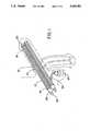
- FIG. 1is a perspective view of a typical prosthesis of the subject invention in its implanted state.
- FIG. 2is a preferred implantable prosthesis in accordance with this invention in a longitudinal cross-sectional view.
- FIG. 3is a transverse cross-sectional view along the axis 2--2 of the prosthesis of FIG. 2.
- FIG. 4is an enlarged longitudinal cross-sectional view of the deflation valve shown in FIG. 2.
- FIG. 5is a transverse cross-sectional views along the axis 3--3 of the prosthesis of FIG. 2.
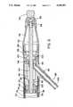
- FIG. 6is an enlarged cross-sectional view of the inflation valve assembly and reservoir shown in FIG. 2 with ingressing passageway from the pump bulb.
- FIG. 7is a transverse cross-sectional view along the axis 4--4 of the prosthesis of FIG. 2.
- a non-unitary inflatable penile prosthetic device 10is shown in FIG. 1. It comprises an implantable cylinder or tubular enclosure 12, and a pump bulb 24 implantable in the scrotum in fluid communication with cylinder 12. Normally a cylinder 12 is implanted in each corpus cavernosum, both then in fluid communication with the pump bulb 24. However, it is possible to utilize only one cylinder in one corpus cavernosum.
- the outer layer of the device 10is composed of a material which is physiologically inert or biocompatible.
- a material which is physiologically inert or biocompatibleis silicon rubber, but any material known to be useful for artificial devices to be implanted in the body can be employed.
- the cylinder 12 depicted in FIG. 1includes a proximal portion 14, a medial portion 16 and a distal portion 18.
- the proximal portion 14defines a reservoir 50.
- Conveniently rear tip 28has a slightly tapered configuration.
- a rear tip extender 22, shown in FIG. 1, preferably of the type disclosed in U.S. Pat. No. 5,010,882may be provided to lengthen the device 10, if desired.
- Reservoir 50defines a reservoir chamber 52.
- the distal portion 18 shown in FIG. 1advantageously includes a front tip 20 that is preferably substantially rigid, so as to resist buckling when in use in the erect state.
- the tip 20is rigid in both the erect and flaccid states.
- the pump bulb 24 shown in FIG. 1is typically of the manually compressible type such as for example described in U.S. Pat. No. 4,590,927.
- Tubing (or tubings) 26, as shown in FIG. 1,enables pump 24 to be in fluid communication with cylinder 12 (or cylinders, if two are used).
- the medial portion 16defines pressurizable chamber 38.
- This medial portionis positioned along the length of the cylinder 12 so that it is also medially disposed along the length of the corpus cavernosum.
- Outer layer 32 of said medial portion 16is preferably comprised of corrugated tubing typically made of a liquid impervious material such as silicone.
- longitudinal passageway 78Concentrically defined within said outer layer 32 is longitudinal passageway 78, shown in FIG. 3.
- passagewaycan also be represented as multiple passageways or channels 78A.
- Pressurizable chamber 38is defined interiorly of said passageway 78, and is comprised of two layers, i.e.
- the non-distensible layer 34may be take a variety of forms, but advantageously is formed from a tubular section of woven dacron material, such as a prosthetic vascular graft material.
- the inner layer 36can also take a variety of forms, but advantageously is formed from a tubular section of a liquid impervious material such as silicone.
- deflation block 30Located in the front end of the cylinder 12 anteriorly to pressurizable chamber 38 is deflation block 30 which will be more definitively described hereinafter with reference to FIG. 4. This block is in fluid communication with reservoir 50 through passageway 78 also as hereinafter described.
- passageway 78is, as stated, longitudinally disposed along the length of cylinder 12 between distal portion 18 and proximal portion 14 and serves to convey fluid during deflation, as hereinafter described, back to the reservoir 50.
- passageway 78is in reality a series of passageways, as shown more clearly in FIG. 3. These passageways (78A) are interconnected with each other by means of outlet ring channel 68 and reservoir ring channel 58 shown in FIG. 6.
- the corrugated configuration of outer layer 32 defining the passageways 78Ais particularly advantageous in the practice of this invention, because it permits an easier streching of the medial portion when the cylinder 12 is bent or hinged, which as will be shown later is important to the operation of the device.
- the corrugated shapeserves to assist the assumption of a flaccid mode because there is virtually no resistance to a circumferential re-shaping when the device 10 is hinged in order to assume the flaccid mode. It has also been found that because this configuration re-shapes with a minimum of force, stress upon the silicone of the outer tubing is reduced with improvement in the friction-caused wear-time of said silicone.
- U.S. Pat. No. 5,010,882a vexing problem with most penile implants is their failure to resume the flaccid condition with a minimum of effort and a maximum (or near maximum) of certainty.
- a unique feature of the invention described in U.S. Pat. No. 5,010,882was a deflation valve which provides a quick and sure means (and method) for effecting a quick and sure return of the penis containing the penile implant from the erect to flaccid state.
- the deflation valve of U.S. Pat. No. 5,010,882is employed, with slight variations, for the purpose set forth in the aforementioned patent. However, as stated heretofore, in the practice of the subject invention, this valve is usually disposed in the front end of the cylinder 12.
- the deflation valve(of valve block 30) operates on a pressure differential basis.
- a poppet 82which preferably comprises a head 74 and a shaft 72.
- Poppet head 74is typically held in sealing contact with housing 31 by means of precalibrated spring 80 and also by the fluid pressure exerted by the fluid in the rear chamber 86 which is in constant fluid communication with the pressurized chamber 38.
- the pressure in front chamber 64 and rear chamber 86is the same.
- Front chamber 64 and rear chamber 86are in fluid communication with each other through fluid resistor means 88.
- This element 88provides a predetermined time-deferred resistance to fluid flow to and from front chamber 64 and rear chamber 86.
- This element 88may be of several types known in the art, but typically is one of the kind which defines a labyrinth type fluid passage such as one formed by a plurality of axially aligned, perforated disks which are adapted to define a restrictive path for fluid flow.
- Partition 66is preferably spaced apart from and in front of poppet shaft 72 and is designed to impact upon the poppet shaft when the pressure in front chamber 64 is sufficiently high. If said pressure is sufficiently higher then the pressure in rear chamber 86, the necessary extent of which is preset and predetermined, the partition 66 will distend and impact upon the poppet shaft with sufficient force to break the sealing contact of the poppet head 74 with valve seat 84 thereby opening the deflation valve.
- Middle chamber 92is, as shown, disposed about the poppet shaft medial to the front chamber 64 and rear chamber 86.
- FIG. 3depicts a transverse cross-sectional view along the axis 2--2 of FIG. 2 through the deflation valve block 30.
- This figureshows the relative disposition of the corrugated outer layer 32 and the multiplicity of passageways, represented by 78A.
- the non-distensible layer 34referred to with respect to pressurizable chamber 38, which layer extends into and is fixed onto the outer surface of the housing 31 of deflation valve block 30. It also extends to the external surface of the inflation block 42 shown in FIG. 6 and is also affixed thereto.
- inflation assembly or block 42located to the rear of pressurizable chamber 38 is a unique feature of this invention, namely inflation assembly or block 42.
- Inflation block 42is defined within the aforementioned proximal portion 18.
- pump bulb 24Disposed separately from cylinder 12, such as in the scrotum, is pump bulb 24. If desired, pump bulb 24 can be located elsewhere in the body, e.g. the abdomen, but it is preferred to place pump bulb 24 in the scrotum because the pump will be easier for the user to reach and operate.
- pump bulb 24is pump chamber 106. When pump bulb 24 is squeezed the fluid of said chamber is forced into tubing passageway 104 which is defined within tubing 26.
- adapter 62which function is to cap pump chamber 106 and serve as an adapter for tubing 26.
- Passageway 104is in fluid communication with inflation chamber 96 of inflation block 42.
- inflation block 42comprises an inflation chamber 96 which is circumferentially disposed about stiffener 44, the latter extending throughout most of the length of the proximal portion 14.
- Inflation chamber 96is in fluid communication with pump chamber 106 through tubing passageway 104 at a point between front check valve formed by skirt 94, and rear check valve formed by rear skirt 46. Situated immediately rearwardly adjacent to rear skirt 46 are rear skirt passageways 98 which are in fluid communication with reservoir chamber 52 of reservoir 50 through passageways 100 located in stiffener flange 102. As stated, reservoir 50 is placed rearwardly in proximal portion 14. Stiffener flange 102 is disposed at a medial point in said proximal portion between rear skirt passageways 98 and inlet hole 48 to fix the stiffener 44 in the rear part of the cylinder.
- Snap washer 40is disposed in front of skirt 94 to prevent inadvertent leakage of fluid from pressurizable chamber 38 into inflation chamber 96 through the front check valve when the chamber 38 is bent during intercourse or to effect deflation.
- the snap washer 40defines a point beyond which the chamber 38 and adjacent front portion of inflation blank 42 cannot be bent.
- FIG. 5is a transverse cross-sectional view of the rearward portion of inflation block 42 along the axis 3--3 of FIG. 2, which depicts in cross-sectional emphasis, the position of flange passageways 100 which enables fluid to pass from reservoir 50 into inflation chamber 96.
- FIG. 7is a further transverse cross-sectional view of inflation block 42 through the anterior position thereof, depicting the position in cross-sectional emphasis, of front skirt passageways 92 which permit the flow of fluid from inflation chamber 96 into pressurizable chamber 38.
- passageways 78Aare shown in transverse section.
- a sufficient amount of fluidis loaded into the device 10 in any suitable manner, such as for example through filling passageway 54 which is opened or closed employing reservoir plug 56.
- This procedureis described in U.S. Pat. No. 4,590,927.
- the prosthesisis implanted within the corpus cavernosum of the patient utilizing conventional surgical techniques well known in the implantation of penile prosthetic devices. Rear tip extenders can be employed to achieve a correct fit.
- the userinitially compresses the manually compressible pump bulb 24 which, as stated, is preferably located in the scrotum.
- the compression of the pump bulb 24forces fluid contained in the pump chamber 106 into passageway 104 and then into inflation chamber 96 of inflation block 42.
- the passage of fluid into chamber 96increases the pressure therein thereby creating a positive pressure differential between said chamber and anteriorly adjacent pressurizable chamber 38.
- front skirt or sleeve 94is forced opened permitting fluid to pass into pressurizable chamber 38.
- positive pressure differential between inflation chamber 96 and reservoir chamber 54keeps rear skirt or sleeve 54 closed preventing fluid transmission from pump to reservoir.
- the sequence of fluid flowis from pump to pressurizable chamber (through the inflation block chamber and front valve or skirt 94), then on releasing of the pump bulb, with consequent vacuum and suction, from reservoir to pump; and then again from pump to pressurizable chamber; until full inflation and erection occurs.
- valve of deflation block 30which in the practice of this invention is located in the distal (front) portion of device 10.
- Deflation valve 30is normally in a closed mode due to the compression force of the spring 80 and, when pressurized, the pressure of the rear chamber 86.
- the fluid pressure in the rear chamber 86 and front chamber 64 of the deflation valve 30is the same as in the pressurizable chamber 38, when the device 10 is in a flaccid or erect position.
- the userAfter inflation, the user initially bends the penis somewhere along the pressurizable chamber 38, up or down, to or slightly more than a predetermined minimum angle which is typically established by the manufacturer of the prosthesis.
- the anglecan be set for operation at 50°-60° up or down from the original plane.
- the exact angle to be utilizedis within the confines of practicality and user convenience.
- the fluid pressure in the front chamber 64 of the deflation valvewill also increase and will become equal to the increased fluid pressure of the rear chamber 86 and the pressurizable chamber 38. This will occur, however, after a short time delay caused by the fine-deferred passage of fluid from the front chamber to the rear chamber through the fluid resistor 88.
- the time delay(which can be predetermined) required to equalize pressure in chamber 38 and chamber 64, depends on the flow configuration of fluid resistor 88, the pressure differential between the front and rear chambers shortly after the penis is bent to the deflation angle, and the compliance of the front chamber 64, i.e. the ease with which the latter will expand under pressure.
- the increased pressure in the front chamber(while the same as that of the rear chamber) deflects the distensible partition or diaphragm 66 towards the poppet shaft 72. This deflection is directly proportional to the front chamber pressure and to the diameter of the diaphragm, and is inversely proportional to the thickness of the diaphragm.
- the userbrings the penis back to the straight position abruptly.
- the "time delays" referred toare measurement in seconds, e.g. on the order of 5 -10 seconds.
- the fluid pressure in the pressurizable chamber 38 and the rear chamber 86almost immediately returns to the initial level (i.e. to that level before the penis was bent to the deflation angle).
- the fluid pressure of the front chamber 64will not return to the initial pressure as quickly i.e. it will remain higher for some time, (measured again in seconds) because the return flow of fluid from the front chamber 64 to the rear chamber 86 is again time-deferred because of the fluid resistor 88.
- the pressure conditions which will open the deflation valvecan not require that the pressure of the front chamber of the valve be higher than that of the rear chamber.
- the same, or essentially the same, pressure in the rear chambercan impact with sufficient force on the poppet to cause the valve to assume an open mode, if the area of the wall of the movable or distensible partition is sufficiently larger than the area of the poppet head. The same time deferred sequence will then still serve to shift the pressures from the rear to front chamber.
- the force exertedwill be proportional to the area of the partition as well as the pressure of the rear chamber, the latter pressure need not be greater than that of the rear chamber to cause the distensible or movable partition to impact upon the poppet with sufficient force to cause the latter to break sealing contact with the valve housing.
Landscapes
- Health & Medical Sciences (AREA)
- Reproductive Health (AREA)
- Cardiology (AREA)
- Oral & Maxillofacial Surgery (AREA)
- Transplantation (AREA)
- Engineering & Computer Science (AREA)
- Biomedical Technology (AREA)
- Heart & Thoracic Surgery (AREA)
- Vascular Medicine (AREA)
- Life Sciences & Earth Sciences (AREA)
- Animal Behavior & Ethology (AREA)
- General Health & Medical Sciences (AREA)
- Public Health (AREA)
- Veterinary Medicine (AREA)
- Prostheses (AREA)
- Orthopedics, Nursing, And Contraception (AREA)
Abstract
Description
Claims (13)
Priority Applications (6)
| Application Number | Priority Date | Filing Date | Title |
|---|---|---|---|
| US07/873,473US5263981A (en) | 1992-04-24 | 1992-04-24 | Implantable penile prosthesis |
| CA002131915ACA2131915C (en) | 1992-04-24 | 1993-02-24 | Implantable penile prosthesis |
| EP93906077AEP0637233B1 (en) | 1992-04-24 | 1993-02-24 | Implantable penile prosthesis |
| JP5519240AJP2854979B2 (en) | 1992-04-24 | 1993-02-24 | Implantable penis prosthesis |
| PCT/US1993/001477WO1993021872A1 (en) | 1992-04-24 | 1993-02-24 | Implantable penile prosthesis |
| DE69307690TDE69307690T2 (en) | 1992-04-24 | 1993-02-24 | IMPLANTABLE PENIS PROSTHESIS |
Applications Claiming Priority (1)
| Application Number | Priority Date | Filing Date | Title |
|---|---|---|---|
| US07/873,473US5263981A (en) | 1992-04-24 | 1992-04-24 | Implantable penile prosthesis |
Publications (1)
| Publication Number | Publication Date |
|---|---|
| US5263981Atrue US5263981A (en) | 1993-11-23 |
Family
ID=25361704
Family Applications (1)
| Application Number | Title | Priority Date | Filing Date |
|---|---|---|---|
| US07/873,473Expired - LifetimeUS5263981A (en) | 1992-04-24 | 1992-04-24 | Implantable penile prosthesis |
Country Status (6)
| Country | Link |
|---|---|
| US (1) | US5263981A (en) |
| EP (1) | EP0637233B1 (en) |
| JP (1) | JP2854979B2 (en) |
| CA (1) | CA2131915C (en) |
| DE (1) | DE69307690T2 (en) |
| WO (1) | WO1993021872A1 (en) |
Cited By (51)
| Publication number | Priority date | Publication date | Assignee | Title |
|---|---|---|---|---|
| US5823991A (en)* | 1995-07-31 | 1998-10-20 | Shim; Youngtack | Penile erection assist device and method |
| US6475137B1 (en)* | 2000-10-13 | 2002-11-05 | James Elist | Subcutaneous penile implant |
| US20040138523A1 (en)* | 2002-12-02 | 2004-07-15 | Ams Research Corporation | Implantable pump |
| US20040220447A1 (en)* | 2003-03-10 | 2004-11-04 | Morningstar Randy L. | Implantable penile prosthesis pump |
| US20040225182A1 (en)* | 2002-11-14 | 2004-11-11 | Eid J. Francois | Penile prosthesis and surgical instruments for implantation of penile prostheses |
| US20050014993A1 (en)* | 2003-06-06 | 2005-01-20 | Mische Hans A. | Inflatable penile prosthesis with volume displacement materials and devices |
| US20050043581A1 (en)* | 2003-04-25 | 2005-02-24 | Ling Jeremy J. | Penile prosthesis with improved tubing junction |
| US20050113638A1 (en)* | 2003-10-02 | 2005-05-26 | Kuyava Charles C. | Implantable penile prosthesis pump |
| US20060135845A1 (en)* | 2004-12-17 | 2006-06-22 | Ams Research Corporation | Implantable penile prosthesis pump |
| WO2006096001A1 (en)* | 2005-03-08 | 2006-09-14 | Ssclinic Corp. | Inflatable prosthesis for aiding penile erection and augmentation |
| US20070175487A1 (en)* | 2006-01-27 | 2007-08-02 | Eid J Francois | Disposable Surgical Drape |
| US7658196B2 (en) | 2005-02-24 | 2010-02-09 | Ethicon Endo-Surgery, Inc. | System and method for determining implanted device orientation |
| US20100082057A1 (en)* | 2008-09-30 | 2010-04-01 | Borkon William D | Variable rigidity vaginal dilator and use thereof |
| US20100160723A1 (en)* | 2008-12-23 | 2010-06-24 | Kuyava Charles C | System to transport components of implantable penile prostheses |
| US7775215B2 (en) | 2005-02-24 | 2010-08-17 | Ethicon Endo-Surgery, Inc. | System and method for determining implanted device positioning and obtaining pressure data |
| US7775966B2 (en) | 2005-02-24 | 2010-08-17 | Ethicon Endo-Surgery, Inc. | Non-invasive pressure measurement in a fluid adjustable restrictive device |
| US7844342B2 (en) | 2008-02-07 | 2010-11-30 | Ethicon Endo-Surgery, Inc. | Powering implantable restriction systems using light |
| US20110054250A1 (en)* | 2009-08-27 | 2011-03-03 | Coloplast A/S | Penile prosthesis cap, assembly, and implantation tool |
| US7927270B2 (en) | 2005-02-24 | 2011-04-19 | Ethicon Endo-Surgery, Inc. | External mechanical pressure sensor for gastric band pressure measurements |
| US7946975B2 (en) | 2005-04-08 | 2011-05-24 | Ams Research Corporation | Fluid reservoir for penile implant devices |
| US20110201880A1 (en)* | 2010-02-12 | 2011-08-18 | Fogarty Terence M | Inflatable penile prosthesis with spool valve |
| US8016745B2 (en) | 2005-02-24 | 2011-09-13 | Ethicon Endo-Surgery, Inc. | Monitoring of a food intake restriction device |
| US8016744B2 (en) | 2005-02-24 | 2011-09-13 | Ethicon Endo-Surgery, Inc. | External pressure-based gastric band adjustment system and method |
| US8034065B2 (en) | 2008-02-26 | 2011-10-11 | Ethicon Endo-Surgery, Inc. | Controlling pressure in adjustable restriction devices |
| US8057492B2 (en) | 2008-02-12 | 2011-11-15 | Ethicon Endo-Surgery, Inc. | Automatically adjusting band system with MEMS pump |
| US8066629B2 (en) | 2005-02-24 | 2011-11-29 | Ethicon Endo-Surgery, Inc. | Apparatus for adjustment and sensing of gastric band pressure |
| US8100870B2 (en) | 2007-12-14 | 2012-01-24 | Ethicon Endo-Surgery, Inc. | Adjustable height gastric restriction devices and methods |
| US8109870B2 (en) | 2006-11-10 | 2012-02-07 | Ams Research Corporation | Inflatable penile prosthesis bypass valve noise reduction |
| US8114011B2 (en) | 2007-10-23 | 2012-02-14 | Ams Research Corporation | Corrugated inflatable penile prosthesis cylinder |
| US8114345B2 (en) | 2008-02-08 | 2012-02-14 | Ethicon Endo-Surgery, Inc. | System and method of sterilizing an implantable medical device |
| US8123674B2 (en) | 2007-11-12 | 2012-02-28 | Ams Research Corporation | Corrugated expansion-constraining sleeve for an inflatable penile prosthesis cylinder |
| US8142452B2 (en) | 2007-12-27 | 2012-03-27 | Ethicon Endo-Surgery, Inc. | Controlling pressure in adjustable restriction devices |
| US8152710B2 (en) | 2006-04-06 | 2012-04-10 | Ethicon Endo-Surgery, Inc. | Physiological parameter analysis for an implantable restriction device and a data logger |
| US8187162B2 (en) | 2008-03-06 | 2012-05-29 | Ethicon Endo-Surgery, Inc. | Reorientation port |
| US8187163B2 (en) | 2007-12-10 | 2012-05-29 | Ethicon Endo-Surgery, Inc. | Methods for implanting a gastric restriction device |
| US8192350B2 (en) | 2008-01-28 | 2012-06-05 | Ethicon Endo-Surgery, Inc. | Methods and devices for measuring impedance in a gastric restriction system |
| US20120157764A1 (en)* | 2010-12-21 | 2012-06-21 | Ams Research Corporation | Adjustable Length Rear Tip Extender for Penile Prosthesis |
| US8221439B2 (en) | 2008-02-07 | 2012-07-17 | Ethicon Endo-Surgery, Inc. | Powering implantable restriction systems using kinetic motion |
| US8233995B2 (en) | 2008-03-06 | 2012-07-31 | Ethicon Endo-Surgery, Inc. | System and method of aligning an implantable antenna |
| US8276591B2 (en) | 2000-12-27 | 2012-10-02 | Ams Research Corporation | Diaphragm based spontaneous inflation inhibitor in a pump for an inflatable prosthesis |
| US8337389B2 (en) | 2008-01-28 | 2012-12-25 | Ethicon Endo-Surgery, Inc. | Methods and devices for diagnosing performance of a gastric restriction system |
| US8377079B2 (en) | 2007-12-27 | 2013-02-19 | Ethicon Endo-Surgery, Inc. | Constant force mechanisms for regulating restriction devices |
| US8591532B2 (en) | 2008-02-12 | 2013-11-26 | Ethicon Endo-Sugery, Inc. | Automatically adjusting band system |
| US8591395B2 (en) | 2008-01-28 | 2013-11-26 | Ethicon Endo-Surgery, Inc. | Gastric restriction device data handling devices and methods |
| US8870742B2 (en) | 2006-04-06 | 2014-10-28 | Ethicon Endo-Surgery, Inc. | GUI for an implantable restriction device and a data logger |
| US8911350B2 (en) | 2007-10-23 | 2014-12-16 | Ams Research Corporation | Malleable prosthesis with enhanced concealability |
| US8939889B1 (en) | 2013-08-22 | 2015-01-27 | Coloplast A/S | Pump bulb for an implantable penile prosthetic |
| US9084678B2 (en) | 2012-01-20 | 2015-07-21 | Ams Research Corporation | Automated implantable penile prosthesis pump system |
| WO2014052729A3 (en)* | 2012-09-27 | 2015-07-30 | Ams Research Corporation | Implantable penile prosthesis |
| US11432929B2 (en) | 2015-12-31 | 2022-09-06 | Menova International, Inc. | Prosthesis for improved penis function |
| USRE50300E1 (en) | 2015-12-31 | 2025-02-18 | Menova International, Inc. | Prosthesis for improved penis function |
Families Citing this family (7)
| Publication number | Priority date | Publication date | Assignee | Title |
|---|---|---|---|---|
| US7648456B2 (en)* | 2005-04-01 | 2010-01-19 | Coloplast A/S | Adapter for penile prosthesis tip extender |
| US9173739B2 (en) | 2009-01-29 | 2015-11-03 | Peter Forsell | Implant comprising an expandable section |
| US9498333B2 (en) | 2014-09-30 | 2016-11-22 | Coloplast A/S | Penile prosthetic insert with a body having a channel and a method for implantation of a penile prosthetic |
| EP3001980B1 (en)* | 2014-09-30 | 2019-11-06 | Coloplast A/S | A penile prosthetic insert with a body having a channel |
| US9907653B2 (en) | 2015-07-27 | 2018-03-06 | Coloplast A/S | Pump bulb for an implantable penile prosthetic |
| US10729546B2 (en) | 2017-02-02 | 2020-08-04 | Coloplast A/S | Inflatable penile prosthetic system |
| US20190365540A1 (en)* | 2018-05-31 | 2019-12-05 | Fidelis Medical Ltd. | Kink resistant multiple lumen pressurized fluid tube |
Citations (16)
| Publication number | Priority date | Publication date | Assignee | Title |
|---|---|---|---|---|
| US3853122A (en)* | 1973-10-12 | 1974-12-10 | B Strauch | Method and device for achieving a penile erection |
| US3954102A (en)* | 1974-07-19 | 1976-05-04 | American Medical Systems, Inc. | Penile erection system and methods of implanting and using same |
| US4009711A (en)* | 1976-03-17 | 1977-03-01 | Uson Aurelio C | Penile prosthesis for the management of erectile impotence |
| US4267829A (en)* | 1979-04-11 | 1981-05-19 | American Medical Systems, Inc. | Penile prosthesis |
| US4353360A (en)* | 1980-10-31 | 1982-10-12 | Medical Engineering Corporation | Penile erectile system |
| US4360010A (en)* | 1980-05-15 | 1982-11-23 | Medical Engineering Corporation | Penile prosthesis |
| US4369771A (en)* | 1981-09-24 | 1983-01-25 | Medical Engineering Corporation | Penile erectile system |
| US4399811A (en)* | 1981-08-04 | 1983-08-23 | Medical Engineering Corporation | Implantable penile erectile system |
| US4590927A (en)* | 1985-02-25 | 1986-05-27 | American Medical Systems, Inc. | Unitary, inflatable penile prosthesis system |
| US4596242A (en)* | 1983-08-26 | 1986-06-24 | Fischell Robert | Method and apparatus for achieving penile erection in a human male |
| US4726360A (en)* | 1986-07-17 | 1988-02-23 | Medical Engineering Corporation | Penile prosthesis |
| US4773403A (en)* | 1987-08-17 | 1988-09-27 | Medical Engineering Corporation | Penile prosthesis |
| US4782826A (en)* | 1987-05-21 | 1988-11-08 | Mentor Corporation | Penile prosthesis |
| US4791917A (en)* | 1981-10-22 | 1988-12-20 | Medical Engineering Corporation | Penile prosthesis |
| US5010882A (en)* | 1989-11-13 | 1991-04-30 | American Medical Systems, Inc. | Implantable penile prosthesis |
| US5048510A (en)* | 1988-08-29 | 1991-09-17 | American Medical Systems, Inc. | Inflatable penile prosthesis with satellite reservoir |
Family Cites Families (1)
| Publication number | Priority date | Publication date | Assignee | Title |
|---|---|---|---|---|
| US4566446A (en)* | 1983-04-08 | 1986-01-28 | Mentor Corporation | Penile prosthesis device |
- 1992
- 1992-04-24USUS07/873,473patent/US5263981A/ennot_activeExpired - Lifetime
- 1993
- 1993-02-24DEDE69307690Tpatent/DE69307690T2/ennot_activeExpired - Lifetime
- 1993-02-24EPEP93906077Apatent/EP0637233B1/ennot_activeExpired - Lifetime
- 1993-02-24JPJP5519240Apatent/JP2854979B2/ennot_activeExpired - Fee Related
- 1993-02-24WOPCT/US1993/001477patent/WO1993021872A1/enactiveIP Right Grant
- 1993-02-24CACA002131915Apatent/CA2131915C/ennot_activeExpired - Fee Related
Patent Citations (16)
| Publication number | Priority date | Publication date | Assignee | Title |
|---|---|---|---|---|
| US3853122A (en)* | 1973-10-12 | 1974-12-10 | B Strauch | Method and device for achieving a penile erection |
| US3954102A (en)* | 1974-07-19 | 1976-05-04 | American Medical Systems, Inc. | Penile erection system and methods of implanting and using same |
| US4009711A (en)* | 1976-03-17 | 1977-03-01 | Uson Aurelio C | Penile prosthesis for the management of erectile impotence |
| US4267829A (en)* | 1979-04-11 | 1981-05-19 | American Medical Systems, Inc. | Penile prosthesis |
| US4360010A (en)* | 1980-05-15 | 1982-11-23 | Medical Engineering Corporation | Penile prosthesis |
| US4353360A (en)* | 1980-10-31 | 1982-10-12 | Medical Engineering Corporation | Penile erectile system |
| US4399811A (en)* | 1981-08-04 | 1983-08-23 | Medical Engineering Corporation | Implantable penile erectile system |
| US4369771A (en)* | 1981-09-24 | 1983-01-25 | Medical Engineering Corporation | Penile erectile system |
| US4791917A (en)* | 1981-10-22 | 1988-12-20 | Medical Engineering Corporation | Penile prosthesis |
| US4596242A (en)* | 1983-08-26 | 1986-06-24 | Fischell Robert | Method and apparatus for achieving penile erection in a human male |
| US4590927A (en)* | 1985-02-25 | 1986-05-27 | American Medical Systems, Inc. | Unitary, inflatable penile prosthesis system |
| US4726360A (en)* | 1986-07-17 | 1988-02-23 | Medical Engineering Corporation | Penile prosthesis |
| US4782826A (en)* | 1987-05-21 | 1988-11-08 | Mentor Corporation | Penile prosthesis |
| US4773403A (en)* | 1987-08-17 | 1988-09-27 | Medical Engineering Corporation | Penile prosthesis |
| US5048510A (en)* | 1988-08-29 | 1991-09-17 | American Medical Systems, Inc. | Inflatable penile prosthesis with satellite reservoir |
| US5010882A (en)* | 1989-11-13 | 1991-04-30 | American Medical Systems, Inc. | Implantable penile prosthesis |
Cited By (78)
| Publication number | Priority date | Publication date | Assignee | Title |
|---|---|---|---|---|
| US5823991A (en)* | 1995-07-31 | 1998-10-20 | Shim; Youngtack | Penile erection assist device and method |
| US6475137B1 (en)* | 2000-10-13 | 2002-11-05 | James Elist | Subcutaneous penile implant |
| US8276591B2 (en) | 2000-12-27 | 2012-10-02 | Ams Research Corporation | Diaphragm based spontaneous inflation inhibitor in a pump for an inflatable prosthesis |
| US20040225182A1 (en)* | 2002-11-14 | 2004-11-11 | Eid J. Francois | Penile prosthesis and surgical instruments for implantation of penile prostheses |
| US7066878B2 (en) | 2002-11-14 | 2006-06-27 | Ams Research Corporation | Penile prosthesis and surgical instruments for implantation of penile prostheses |
| US7874978B2 (en) | 2002-12-02 | 2011-01-25 | Ams Research Corporation | Implantable pump |
| US20040138523A1 (en)* | 2002-12-02 | 2004-07-15 | Ams Research Corporation | Implantable pump |
| US20110087068A1 (en)* | 2002-12-02 | 2011-04-14 | Ams Research Corporation | Implantable Pump |
| US20050250982A1 (en)* | 2002-12-02 | 2005-11-10 | Kuyava Charles C | Implantable pump |
| US6991601B2 (en) | 2002-12-02 | 2006-01-31 | Ams Research Corporation | Implantable pump |
| US8062209B2 (en) | 2002-12-02 | 2011-11-22 | Ams Research Corporation | Implantable pump |
| US7244227B2 (en) | 2003-03-10 | 2007-07-17 | Ams Research Corporation | Implantable penile prosthesis pump |
| US20040220447A1 (en)* | 2003-03-10 | 2004-11-04 | Morningstar Randy L. | Implantable penile prosthesis pump |
| US7169103B2 (en) | 2003-04-25 | 2007-01-30 | Ams Research Corporation | Penile prosthesis with improved tubing junction |
| US20050043581A1 (en)* | 2003-04-25 | 2005-02-24 | Ling Jeremy J. | Penile prosthesis with improved tubing junction |
| US7390296B2 (en) | 2003-06-06 | 2008-06-24 | Ams Research Corporation | Inflatable penile prosthesis with volume displacement materials and devices |
| US20050014993A1 (en)* | 2003-06-06 | 2005-01-20 | Mische Hans A. | Inflatable penile prosthesis with volume displacement materials and devices |
| US20050113638A1 (en)* | 2003-10-02 | 2005-05-26 | Kuyava Charles C. | Implantable penile prosthesis pump |
| US7250026B2 (en) | 2003-10-02 | 2007-07-31 | Ams Research Corporation | Implantable penile prosthesis pump |
| US20060135845A1 (en)* | 2004-12-17 | 2006-06-22 | Ams Research Corporation | Implantable penile prosthesis pump |
| US7914439B2 (en) | 2004-12-17 | 2011-03-29 | Ams Research Corporation | Implantable penile prosthesis pump |
| US7637861B2 (en) | 2004-12-17 | 2009-12-29 | Ams Research Corporation | Implantable penile prosthesis pump |
| US8066629B2 (en) | 2005-02-24 | 2011-11-29 | Ethicon Endo-Surgery, Inc. | Apparatus for adjustment and sensing of gastric band pressure |
| US8016744B2 (en) | 2005-02-24 | 2011-09-13 | Ethicon Endo-Surgery, Inc. | External pressure-based gastric band adjustment system and method |
| US7775215B2 (en) | 2005-02-24 | 2010-08-17 | Ethicon Endo-Surgery, Inc. | System and method for determining implanted device positioning and obtaining pressure data |
| US7775966B2 (en) | 2005-02-24 | 2010-08-17 | Ethicon Endo-Surgery, Inc. | Non-invasive pressure measurement in a fluid adjustable restrictive device |
| US7658196B2 (en) | 2005-02-24 | 2010-02-09 | Ethicon Endo-Surgery, Inc. | System and method for determining implanted device orientation |
| US8016745B2 (en) | 2005-02-24 | 2011-09-13 | Ethicon Endo-Surgery, Inc. | Monitoring of a food intake restriction device |
| US7927270B2 (en) | 2005-02-24 | 2011-04-19 | Ethicon Endo-Surgery, Inc. | External mechanical pressure sensor for gastric band pressure measurements |
| CN101160106B (en)* | 2005-03-08 | 2010-09-22 | 性福诊所株式会社 | Inflatable prosthesis for aiding penile erection and augmentation |
| US7491164B2 (en) | 2005-03-08 | 2009-02-17 | Ss Clinic Corp. | Inflatable prosthesis for aiding penile erection and augmentation |
| WO2006096001A1 (en)* | 2005-03-08 | 2006-09-14 | Ssclinic Corp. | Inflatable prosthesis for aiding penile erection and augmentation |
| US7946975B2 (en) | 2005-04-08 | 2011-05-24 | Ams Research Corporation | Fluid reservoir for penile implant devices |
| US20070175487A1 (en)* | 2006-01-27 | 2007-08-02 | Eid J Francois | Disposable Surgical Drape |
| US8152710B2 (en) | 2006-04-06 | 2012-04-10 | Ethicon Endo-Surgery, Inc. | Physiological parameter analysis for an implantable restriction device and a data logger |
| US8870742B2 (en) | 2006-04-06 | 2014-10-28 | Ethicon Endo-Surgery, Inc. | GUI for an implantable restriction device and a data logger |
| US8109870B2 (en) | 2006-11-10 | 2012-02-07 | Ams Research Corporation | Inflatable penile prosthesis bypass valve noise reduction |
| US8911350B2 (en) | 2007-10-23 | 2014-12-16 | Ams Research Corporation | Malleable prosthesis with enhanced concealability |
| US9517133B2 (en) | 2007-10-23 | 2016-12-13 | Boston Scientific Scimed, Inc. | Malleable prosthesis with enhanced concealability |
| US8114011B2 (en) | 2007-10-23 | 2012-02-14 | Ams Research Corporation | Corrugated inflatable penile prosthesis cylinder |
| US8123674B2 (en) | 2007-11-12 | 2012-02-28 | Ams Research Corporation | Corrugated expansion-constraining sleeve for an inflatable penile prosthesis cylinder |
| US8187163B2 (en) | 2007-12-10 | 2012-05-29 | Ethicon Endo-Surgery, Inc. | Methods for implanting a gastric restriction device |
| US8100870B2 (en) | 2007-12-14 | 2012-01-24 | Ethicon Endo-Surgery, Inc. | Adjustable height gastric restriction devices and methods |
| US8377079B2 (en) | 2007-12-27 | 2013-02-19 | Ethicon Endo-Surgery, Inc. | Constant force mechanisms for regulating restriction devices |
| US8142452B2 (en) | 2007-12-27 | 2012-03-27 | Ethicon Endo-Surgery, Inc. | Controlling pressure in adjustable restriction devices |
| US8337389B2 (en) | 2008-01-28 | 2012-12-25 | Ethicon Endo-Surgery, Inc. | Methods and devices for diagnosing performance of a gastric restriction system |
| US8591395B2 (en) | 2008-01-28 | 2013-11-26 | Ethicon Endo-Surgery, Inc. | Gastric restriction device data handling devices and methods |
| US8192350B2 (en) | 2008-01-28 | 2012-06-05 | Ethicon Endo-Surgery, Inc. | Methods and devices for measuring impedance in a gastric restriction system |
| US7844342B2 (en) | 2008-02-07 | 2010-11-30 | Ethicon Endo-Surgery, Inc. | Powering implantable restriction systems using light |
| US8221439B2 (en) | 2008-02-07 | 2012-07-17 | Ethicon Endo-Surgery, Inc. | Powering implantable restriction systems using kinetic motion |
| US8114345B2 (en) | 2008-02-08 | 2012-02-14 | Ethicon Endo-Surgery, Inc. | System and method of sterilizing an implantable medical device |
| US8057492B2 (en) | 2008-02-12 | 2011-11-15 | Ethicon Endo-Surgery, Inc. | Automatically adjusting band system with MEMS pump |
| US8591532B2 (en) | 2008-02-12 | 2013-11-26 | Ethicon Endo-Sugery, Inc. | Automatically adjusting band system |
| US8034065B2 (en) | 2008-02-26 | 2011-10-11 | Ethicon Endo-Surgery, Inc. | Controlling pressure in adjustable restriction devices |
| US8187162B2 (en) | 2008-03-06 | 2012-05-29 | Ethicon Endo-Surgery, Inc. | Reorientation port |
| US8233995B2 (en) | 2008-03-06 | 2012-07-31 | Ethicon Endo-Surgery, Inc. | System and method of aligning an implantable antenna |
| US8097014B2 (en) | 2008-09-30 | 2012-01-17 | William D. Borkon | Variable rigidity vaginal dilator and use thereof |
| US20100082057A1 (en)* | 2008-09-30 | 2010-04-01 | Borkon William D | Variable rigidity vaginal dilator and use thereof |
| US8702589B2 (en) | 2008-12-23 | 2014-04-22 | Ams Research Corporation | System to transport components of implantable penile prostheses |
| US20100160723A1 (en)* | 2008-12-23 | 2010-06-24 | Kuyava Charles C | System to transport components of implantable penile prostheses |
| US7959556B2 (en)* | 2009-08-27 | 2011-06-14 | Coloplast A/S | Penile prosthesis cap, assembly, and implantation tool |
| US20110054250A1 (en)* | 2009-08-27 | 2011-03-03 | Coloplast A/S | Penile prosthesis cap, assembly, and implantation tool |
| US8241203B2 (en) | 2010-02-12 | 2012-08-14 | Fogarty Terence M | Inflatable penile prosthesis with spool valve |
| US20110201880A1 (en)* | 2010-02-12 | 2011-08-18 | Fogarty Terence M | Inflatable penile prosthesis with spool valve |
| US20120157764A1 (en)* | 2010-12-21 | 2012-06-21 | Ams Research Corporation | Adjustable Length Rear Tip Extender for Penile Prosthesis |
| US9474610B2 (en)* | 2010-12-21 | 2016-10-25 | Boston Scientific Scimed, Inc. | Adjustable length rear tip extender for penile prosthesis |
| US9808343B2 (en) | 2012-01-20 | 2017-11-07 | Boston Scientific Scimed, Inc. | Automated implantable penile prosthesis pump system |
| US9084678B2 (en) | 2012-01-20 | 2015-07-21 | Ams Research Corporation | Automated implantable penile prosthesis pump system |
| EP3508174A1 (en) | 2012-09-27 | 2019-07-10 | Boston Scientific Scimed, Inc. | Implantable penile prosthesis |
| WO2014052729A3 (en)* | 2012-09-27 | 2015-07-30 | Ams Research Corporation | Implantable penile prosthesis |
| US9999508B2 (en) | 2012-09-27 | 2018-06-19 | Boston Scientific Scimed, Inc. | Implantable penile prosthesis |
| US10729547B2 (en) | 2012-09-27 | 2020-08-04 | Boston Scientific Scimed, Inc. | Implantable penile prosthesis |
| USD739530S1 (en)* | 2013-08-22 | 2015-09-22 | Coloplast A/S | Pump bulb with multi-concavity faces for an implantable penile prosthetic |
| US8939889B1 (en) | 2013-08-22 | 2015-01-27 | Coloplast A/S | Pump bulb for an implantable penile prosthetic |
| USD725777S1 (en)* | 2013-08-22 | 2015-03-31 | Coloplast A/S | Pump bulb with three lobes and three multi-concavity faces for an implantable penile prosthetic |
| USD725271S1 (en)* | 2013-08-22 | 2015-03-24 | Coloplast A/S | Pump bulb with three lobes for an implantable penile prosthetic |
| US11432929B2 (en) | 2015-12-31 | 2022-09-06 | Menova International, Inc. | Prosthesis for improved penis function |
| USRE50300E1 (en) | 2015-12-31 | 2025-02-18 | Menova International, Inc. | Prosthesis for improved penis function |
Also Published As
| Publication number | Publication date |
|---|---|
| DE69307690T2 (en) | 1997-05-15 |
| DE69307690D1 (en) | 1997-03-06 |
| CA2131915C (en) | 1996-01-02 |
| JPH07501736A (en) | 1995-02-23 |
| WO1993021872A1 (en) | 1993-11-11 |
| EP0637233B1 (en) | 1997-01-22 |
| JP2854979B2 (en) | 1999-02-10 |
| CA2131915A1 (en) | 1993-11-11 |
| EP0637233A1 (en) | 1995-02-08 |
Similar Documents
| Publication | Publication Date | Title |
|---|---|---|
| US5263981A (en) | Implantable penile prosthesis | |
| US5010882A (en) | Implantable penile prosthesis | |
| US4590927A (en) | Unitary, inflatable penile prosthesis system | |
| US5141509A (en) | Penile prosthesis having means for preventing spontaneous inflation | |
| EP0065853B1 (en) | Penile prosthesis with improved fluid control | |
| US7250026B2 (en) | Implantable penile prosthesis pump | |
| US5048510A (en) | Inflatable penile prosthesis with satellite reservoir | |
| US4895139A (en) | Inflatable penile prosthesis with bend release valve | |
| US7244227B2 (en) | Implantable penile prosthesis pump | |
| US4875472A (en) | Flat coil spring penile prosthesis | |
| US20020082471A1 (en) | Pressure based spontaneous inflation inhibitor in a pump for an inflatable prosthesis | |
| JPS5924824B2 (en) | implantable artificial penis |
Legal Events
| Date | Code | Title | Description |
|---|---|---|---|
| AS | Assignment | Owner name:AMERICAN MEDICAL SYSTEMS, INC., MINNESOTA Free format text:ASSIGNMENT OF ASSIGNORS INTEREST.;ASSIGNORS:POLYAK, MARK;PUGH, ROBERT W., JR.;REEL/FRAME:006110/0808 Effective date:19920423 | |
| FEPP | Fee payment procedure | Free format text:PAYOR NUMBER ASSIGNED (ORIGINAL EVENT CODE: ASPN); ENTITY STATUS OF PATENT OWNER: LARGE ENTITY | |
| STCF | Information on status: patent grant | Free format text:PATENTED CASE | |
| FPAY | Fee payment | Year of fee payment:4 | |
| AS | Assignment | Owner name:WPAMS ACQUISITION CORP., NEW YORK Free format text:ASSIGNMENT OF ASSIGNORS INTEREST;ASSIGNOR:AMERICAN MEDICAL SYSTEMS, INC.;REEL/FRAME:010685/0496 Effective date:19980910 Owner name:AMERICAN MEDICAL SYSTEMS, INC., MINNESOTA Free format text:ASSIGNMENT OF ASSIGNORS INTEREST;ASSIGNOR:WPAMS ACQUISITION CORP.;REEL/FRAME:010685/0505 Effective date:19980702 | |
| AS | Assignment | Owner name:BANK OF AMERICA, N.A., AS AGENT, NORTH CAROLINA Free format text:NOTICE OF GRANT OF SECURITY INTEREST;ASSIGNOR:AMERICAN MEDICAL SYSTEMS, INC., F/K/A WPAMS ACQUISITION CORP.;REEL/FRAME:010795/0619 Effective date:20000417 | |
| FEPP | Fee payment procedure | Free format text:PAYOR NUMBER ASSIGNED (ORIGINAL EVENT CODE: ASPN); ENTITY STATUS OF PATENT OWNER: LARGE ENTITY Free format text:PAYER NUMBER DE-ASSIGNED (ORIGINAL EVENT CODE: RMPN); ENTITY STATUS OF PATENT OWNER: LARGE ENTITY | |
| FPAY | Fee payment | Year of fee payment:8 | |
| AS | Assignment | Owner name:BANK OF AMERICA, N.A., AS AGENT, NORTH CAROLINA Free format text:NOTICE OF GRANT OF SECURITY INTERST;ASSIGNOR:AMERICAN MEDICAL SYSTEMS, INC.;REEL/FRAME:014186/0257 Effective date:20000417 | |
| AS | Assignment | Owner name:AMS RESEARCH CORPORATION, MINNESOTA Free format text:ASSIGNMENT OF ASSIGNORS INTEREST;ASSIGNOR:AMERICAN MEDICAL SYSTEMS INC.;REEL/FRAME:013835/0494 Effective date:20030724 | |
| AS | Assignment | Owner name:AMERICAN MEDICAL SYSTEMS, INC., MINNESOTA Free format text:SECURITY INTEREST RELEASE;ASSIGNOR:BANK OF AMERICA, N.A.;REEL/FRAME:015596/0795 Effective date:20040701 | |
| FPAY | Fee payment | Year of fee payment:12 | |
| AS | Assignment | Owner name:AMERICAN MEDICAL SYSTEMS, INC., MINNESOTA Free format text:RELEASE BY SECURED PARTY;ASSIGNOR:BANK OF AMERICA, N.A., AS AGENT;REEL/FRAME:017846/0709 Effective date:20060628 | |
| AS | Assignment | Owner name:AMERICAN MEDICAL SYSTEMS, INC. F/K/A WPAMS ACQUISI Free format text:RELEASE OF SECURITY INTEREST (SUPERCEDING RELEASE RECORDED ON JULY 30, 2004, AT REEL 015596, FRAME 0795).;ASSIGNOR:BANK OF AMERICA, N.A., AS AGENT;REEL/FRAME:017971/0028 Effective date:20060719 | |
| AS | Assignment | Owner name:AEMRICAN MEDICAL SYSTEMS, INC., MINNESOTA Free format text:RELEASE OF SECURITY INTEREST (SUPERCEEDING RELEASE RECORDED AT REEL/FRAME 017846/0709);ASSIGNOR:BANK OF AMERICA, N.A., AS AGENT;REEL/FRAME:018109/0700 Effective date:20060717 | |
| AS | Assignment | Owner name:MORGAN STANLEY SENIOR FUNDING, INC., AS ADMINISTRA Free format text:SECURITY AGREEMENT;ASSIGNOR:AMS RESEARCH CORPORATION;REEL/FRAME:026632/0535 Effective date:20110617 | |
| AS | Assignment | Owner name:AMS RESEARCH CORPORATION, MINNESOTA Free format text:RELEASE OF PATENT SECURITY INTEREST;ASSIGNOR:MORGAN STANLEY SENIOR FUNDING, INC., AS ADMINISTRATIVE AGENT;REEL/FRAME:032380/0053 Effective date:20140228 |