US5263715A - Dice displaying apparatus for a computer game machine - Google Patents
Dice displaying apparatus for a computer game machineDownload PDFInfo
- Publication number
- US5263715A US5263715AUS07/955,200US95520092AUS5263715AUS 5263715 AUS5263715 AUS 5263715AUS 95520092 AUS95520092 AUS 95520092AUS 5263715 AUS5263715 AUS 5263715A
- Authority
- US
- United States
- Prior art keywords
- dice
- rolling
- die
- display
- display position
- Prior art date
- Legal status (The legal status is an assumption and is not a legal conclusion. Google has not performed a legal analysis and makes no representation as to the accuracy of the status listed.)
- Expired - Fee Related
Links
Images


Classifications
- A—HUMAN NECESSITIES
- A63—SPORTS; GAMES; AMUSEMENTS
- A63F—CARD, BOARD, OR ROULETTE GAMES; INDOOR GAMES USING SMALL MOVING PLAYING BODIES; VIDEO GAMES; GAMES NOT OTHERWISE PROVIDED FOR
- A63F9/00—Games not otherwise provided for
- A63F9/04—Dice; Dice-boxes; Mechanical dice-throwing devices
- A63F9/0468—Electronic dice; electronic dice simulators
- A—HUMAN NECESSITIES
- A63—SPORTS; GAMES; AMUSEMENTS
- A63F—CARD, BOARD, OR ROULETTE GAMES; INDOOR GAMES USING SMALL MOVING PLAYING BODIES; VIDEO GAMES; GAMES NOT OTHERWISE PROVIDED FOR
- A63F9/00—Games not otherwise provided for
- A63F9/20—Dominoes or like games; Mah-Jongg games
- A63F2009/205—Mah-jongg games
- A—HUMAN NECESSITIES
- A63—SPORTS; GAMES; AMUSEMENTS
- A63F—CARD, BOARD, OR ROULETTE GAMES; INDOOR GAMES USING SMALL MOVING PLAYING BODIES; VIDEO GAMES; GAMES NOT OTHERWISE PROVIDED FOR
- A63F9/00—Games not otherwise provided for
- A63F9/24—Electric games; Games using electronic circuits not otherwise provided for
- A63F2009/2448—Output devices
- A63F2009/245—Output devices visual
- A63F2009/2457—Display screens, e.g. monitors, video displays
Definitions
- the present inventionrelates to a computer game machine for displaying images of dice.
- the diceare controlled by push button switches.
- the present inventionhas been made having regard to the state of the art noted above, and its object is to provide a dice displaying apparatus for a computer game machine which gives a psuedo-real feeling of "throwing dice”.
- a dice displaying apparatus for a computer game machinecomprising:
- detecting meansfor detecting an amount and direction of operation of the trackball
- image memory meansfor storing image patterns of each side of the die means expressing varied phases of rolling movement thereof at a plurality of rolling angles
- display control meansfor selectively reading the image patterns of the varied phases of rolling movement from the image memory means based on the rolling angle derived by the display position operating means, and outputting an image pattern selected to the die display position;
- a rolling angle and rolling speed of each dieare derived from an amount and direction of operation of the trackball, and a die display position is determined from the rolling angle and the rolling speed every predetermined interval of time. Then, an image pattern corresponding to the rolling angle of the die is read from the image memory means and outputted to the display position.
- the display meanspresents rolling movement of each die corresponding to the amount and direction of operation of the trackball.
- an operation of the trackballinvolves a hand motion common to an act of "throwing dice”.
- the trackball operationprovides a pseudo-real feeling of "throwing dice”.
- that feeling of "throwing dice”takes a visual form also.
- the display position operating meanshas a function to determine the die display position by adding a slight angle derived from a random number to the rolling angle of each die.
- the rolling direction of the diemay change slightly from time to time even if the trackball is operated in one direction.
- actual diceare cube-shaped, and their rolling direction is not fixed but varies from time to time even when the dice are thrown in the same direction.
- This apparatusis capable of presenting dice by taking into account that "the rolling direction of dice is variable even if the dice are thrown in the same direction.” This promotes the visual effect of dice throwing feeling.
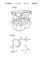
- FIG. 1is a perspective view of a computer game machine according to the present invention
- FIG. 2is a schematic plan view of a trackball
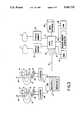
- FIG. 3is a schematic block diagram of a dice displaying apparatus according to the present invention.
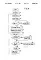
- FIG. 4is a flowchart of a game processing sequence of the computer game machine shown in FIG. 1;
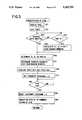
- FIG. 5is a flowchart of a dice presentation subroutine in the flowchart of FIG. 4;
- FIG. 6is a plan view of the computer game machine showing rolling tracks of dice
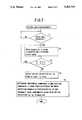
- FIG. 7is a flowchart of a sequence for procurement of trackball control data (amounts and direction of operation);
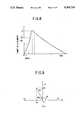
- FIG. 8is graph showing a relationship between amount of trackball operation (count of a counter) and time
- FIG. 9is an explanatory view showing how a rotating speed and a rotating direction of a trackball are derived
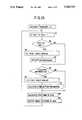
- FIG. 10is a flowchart of interrupt programs 1, 2 included as a subroutine in the flowchart of FIG. 5;
- FIG. 11is an explanatory view showing how a die displaying coordinate position is derived.
- FIG. 12is a schematic view of image patterns.
- FIG. 1is a perspective view showing an outward appearance of a game machine in one embodiment of the present invention.
- This game machineprovides a mechanized version of "craps" which, along with poker, blackjack and roulette, is a typical game played in casinos.
- playersplace bets in desired positions on a craps table on which a layout is printed, two dice are thrown on the table, and the total number shown by the dice and the odds afforded by the positions in which the bets are placed determine wins and losses.
- the role to throw the dice(the thrower is called the shooter) is changed from one player to another in rotation.
- This game machineincludes two CRT displays 1 disposed centrally thereof for displaying the same image as the layout of the craps table and dice presented by computer graphics, and six control panels 2 arranged around the CRT displays 1 to accommodate six players.
- the CRT displays 1 and control panels 2constitute a game deck 3.
- the game machinefurther includes an illuminating table 4 supported on four columns over the game deck 3. Though not shown, the illuminating table 4 has spotlights for illuminating particular players.
- Each control panel 2includes a trackball 5 for controlling the dice, a BET button 6 for betting coins or medals, a payoff return, not shown, for paying out coins or medals, and a speaker, also not shown, for producing a sound effect.
- the trackball 5includes a rolling ball 7 operable by a player and having an illuminating light (not shown), a rotary shaft 8X in contact with the ball 7 and extending in a horizontal direction (X-axis direction) to be rotatable with the ball 7, and a rotary shaft 8Y in contact with the ball 7 and extending in a vertical direction (Y-axis direction) to be rotatable with the ball 7.
- the rotary shafts 8X and 8Yhave detectors 9X and 9Y for detecting the number and direction of rotations thereof, respectively.
- each of the detectors 9X and 9Yincludes a disc 10 mounted on the rotary shaft 8X or 8Y and defining slits 12 and 13 displaced from each other circumferentially of the disk 10.
- a light emitting diode 14 and photodiodes D1 and D2are arranged opposite each other across the slits 12 and 13.
- These detectors 9X and 9Yfurther include an X-counter 30 and a Y-counter 31, respectively, for counting the number of output signals from the photodiodes D1 and D2.
- the X-counter 30 and Y-counter 31are connected to a CPU 15 mounted in each control panel 2. Though not shown in FIG. 3, the BET button 6, the speaker and other components are also connected to the CPU 15. The CPU 15 is connected through a communication line 16 to a main CPU 17.
- ROM 18storing programs of the game
- RAM 19for storing various data derived in the course of play
- image database 20storing image patterns of dice to be described later
- display memories 21 and 22corresponding to the two CRT displays 1
- random number generator 23for generating random numbers in 10 decimal digits.
- the random number generator 23derives a random number Xi from a general formula "Xi ⁇ [aX(i-1)+C]mod ⁇ m".
- signs "a", “C” and “m”represent constants selected at option, and sign "X(i-1)" represents an immediately preceding random number. Constants "a”, “C” and “m” are selected so that the random number Xi derived each time has a different value and that all available values of the random number are evenly used.
- a shooter change flagis set by way of initialization.
- step S2bets are detected.
- Each playerafter inserting a medal or medals into the game machine, operates the trackball 5 and presses the BET button 6 to place the medal or medals in a desired position as a stake. This is a betting action, and which control panels 2 are taking part in the game is determined by detecting the bets.
- step S3is executed to start a "7 to 20 seconds" timer. During this period, any additional bets are accepted (steps S4 and S5), thus admitting further participants into the game.
- step S6is executed to select the shooter (the player to throw the dice by operating the trackball 5). Then, the selected shooter is indicated by turning on the spotlight in the illuminating table 4 to illuminate the shooter, and at the same time lighting the trackball 5 on the control panel 2 of the shooter.
- step S7two rolling dice are presented on the CRT displays 1 in response to the rolling direction and speed of the trackball 5 manipulated by the shooter. Processing for this dice presentation will be described later.
- the number of medal or coils to be paid to each playeris calculated from the total number shown by the two dice and the odds afforded by the bet position on the craps table.
- step S9whether the shooter is to be changed or not is determined from the total number shown by the two dice (the rule for this decision being immaterial and not described herein).
- the operationmoves to step S10 to set the shooter change flag as necessary, before moving to step S11. If the same player is allowed to continue as the shooter, step S11 is executed without setting the shooter change flag.
- step S11whether there is any big winner or not is determined from the numbers of coins calculated for payment and a predetermined reference number of coins. If there is, step S12 is executed to emphasize the big winner by illuminating him or her with the spotlight in the illuminating table 4.
- step S13coins are paid to winners for settlement. This settlement is carried out by displaying the number of coins paid on a digital display provided on each control panel, and dispensing the coins through the payoff return of the game machine when the player quits the game or upon completion of each play. The settled or lost bets are cleared.
- step S14the spotlight and sound effect are turned off. Then the operation returns to step S2 to wait for bets.
- FIG. 6is a schematic plan view of the game deck 3 shown in FIG. 1, with only one control panel 2 shown for expediency.
- the images of dice displayedare read from the image database 20 shown in FIG. 3 and transferred to the display memory 21 or 22.
- the image database 20stores;
- FIG. 12shows part of image patterns relating to a one-dot side of each die.
- References P1, P2 and so ondenote the image patterns of varied phases of the die making one rotation. These image patterns are provided for each of rolling directions A1-A12.
- the main CPU 17reads the image patterns of sides of the dice facing up the previous time (or of any sides if this is going to be a come-out roll), and transmits these image patterns to the display memory 21 or 22 for presentation on the CRT display 1.
- the coordinate positions for presentation on the CRT displays 1are predetermined in relation to the respective control panels 2. As shown in FIG. 6, for example, it is assumed that the die d has a coordinate position (Xd0, Yd0) for presentation, and the die D a coordinate position (XD0, YD0) for presentation, both in relation to the particular control panel 2.
- step S72a three-second timer is started. Then, it is determined whether or not the shooter operates the trackball 5 within the three seconds to cause the CPU 15 in the control panel 2 to output control data, that is whether or not the main CPU 17 receives the control data within the three seconds (step S73).
- the control data output processing by the CPU 15will be described with reference to the flowchart of FIG. 7.
- step T2When the CPU 15 in the control panel 2 determines at step T1 that the trackball 5 has been operated, the CPU 15 executes step T2. At this step, the CPU 15, after starting a 20 ms timer, reads counts Xi and Yi from X-counter 30 and Y-counter 31 and resets these counters every 20 ms. At step S3, the CPU 15 compares current counts "Xi", “Yi” and immediately preceding counts "X(i-1)", "Y(i-1)".
- the comparisonis made by using a register A and a register B included in the CPU 15 (see FIG. 3).
- the immediately preceding counts "X(i-1)” and “Y(i-1)”are recorded in the registers A and B, respectively, for comparison with the current counts "Xi” and "Yi”. If Xi is greater than X(i-1) and Yi greater than Y(i-1), the contents of registers A and B are renewed with "Xi” and "Yi". This operation is repeated until Xi>X(i-1) and Yi>Y(i-1) are negated.
- FIG. 8shows, by way of example, a relationship between count of the X-counter 30 and time when the trackball 5 is operated.
- count Xi recorded in the register Aultimately reaches a maximum count Xm as shown.
- count Yi recorded in the register Bultimately reaches a maximum count Ym.
- the maximum counts Xm and Ym of the X-counter 30 and Y-counter 31have an upper limit set to "140" and a lower limit set to "20". That is, the maximum counts range from “20” to "140", and counts less than "20” indicate that the trackball 5 has not been operated.
- Step T4is executed to derive an initial velocity Vx in the X-direction of the trackball 5 from the value Xm, and an initial velocity Vy in the Y-direction of the trackball 5 from the value Ym. Since the values Xm and Ym are counts obtained in the time interval of 20 ms, the initial velocity Vx per 1 ms is expressed by "Xm/20" and the initial velocity Vy per 1 m by "Ym/20".
- Directional components "+ and -"are set with respect to the horizontal direction (X) and vertical direction (Y) as shown in FIG. 2. This arrangement is set such that the vertical direction (Y) has the "+” side extending from the trackball 5 toward the CRT displays 1.
- clockwise rotation of the rotary shafts 8X and 8Ycorresponds to rotation in "+" direction, and counterclockwise rotation thereof to rotation in "-" direction.
- the slit 13 formed in the disc 10 attached to each rotary shaft 8X or 8Yfirst passes across an optical path of the light emitting diode 14, whereby the output signal of the photodiode D2 has a leading phase with respect to that of the photodiode D1.
- the directional components of the trackball 5are determined from such differences in phase.
- the main CPU 17receives data of the initial velocities Vx and Vy derived as above, and the horizontal component H and vertical component V determined.
- the control data noted hereinbeforerefer to these data.
- step S76Reverting to the flowchart of FIG. 5, after the control data are inputted to the main CPU 17, the operation moves to step S76. On the other hand, if no control data are inputted within the period of three seconds, that is if the shooter does not operate the trackball 5, the operation moves to step S75 to prepare control data automatically.
- step S75and 8-digit data is first selected by removing digits at opposite ends of a 10-digit data generated by the random number generator 23, in order to prepare control data including initial velocities Vx and Vy, horizontal component H and vertical component V.
- the initial velocities Vx and Vymay be expressed by using the above remainder values "0 to 239".
- the remainder values "0 to 119”represent maximum counts “20 to 140" for a plus directional component
- the remainder values "120 to 239”represent maximum counts "20 to 140” for a minus directional component. Subsequently, these maximum counts are divided by 20, as noted hereinbefore, to obtain data of initial velocities Vx and Vy in 1 ms.
- control data inputted at step S73 or the control data prepared at step S75include a minus directional component Vx and a plus directional component Vy.
- the velocity V0is derived from the following equation (1): ##EQU1## where N is a predetermined coefficient.
- Amplitude ⁇ of the velocity V0 with respect to the horizontal component His derived from the above angle ⁇ 3 and the signs of horizontal component H and vertical component V, as follows:
- This amplitude ⁇may be employed as the rolling angles ⁇ 1 and ⁇ 2 of the dice d and D.
- a slight angle ⁇ 4(e.g. 4 to 10 degrees) obtained from random numbers is added to the amplitude ⁇ to produce rolling angles ⁇ 1 and ⁇ 2.
- the rolling angle ⁇ 1is amplitude ⁇ + ⁇ 4
- the rolling angle ⁇ 2is amplitude ⁇ - ⁇ 4.
- the slight angle ⁇ 4is derived as follows.
- an 8-digit datais selected by removing digits at opposite ends of a 10-digit data generated by the random number generator 23.
- the selected 8-digit decimalis divided by "7", to obtain a remainder "0 to 6". Since the slight angle ⁇ 4 may be selected from the range of 4 to 10 degrees, the values of the remainder "0 to 6" are made to correspond to these degrees. Thus, the slight angle ⁇ 4 is 4 degrees when the remainder is "0", 5 degrees when the remainder is "1", . . . , and 10 degrees when the remainder is "6".
- the rolling angles ⁇ 1 and ⁇ 2 of the dice d and Dare calculated by using the slight angle ⁇ 4 obtained from the random number.
- the numbers shown by the dice d and Dare determined by using random numbers.
- the numbers shown by the dice d and Dmay be from 1 to 6.
- 8-digit datais selected by removing digits at opposite ends of a 10-digit data generated by the random number generator 23.
- the selected 8-digit decimalis divided by "6", to obtain a remainder "0 to 5".
- the values of the remainder "0 to 5"are made to correspond to the numbers "1 to 6" shown by the dice d and D, thereby to determine the numbers shown by the dice d and D.
- step S78the spotlight illuminating the shooter and the light of his or her trackball 5 are turned off.
- interrupt programs 1 and 2are set every 16 ms to display the dice d and D in rolling movement on the CRT displays 1, based on the velocities V1 and V2 and rolling angles ⁇ 1 and ⁇ 2 of the dice d and D.
- the interrupt program 1relates to display processing for the die d
- the interrupt program 2relates to display processing for the die D.
- the interrupt programs 1 and 2are executed until the velocities V1 and V2 of the dice d and D become zero, i.e. until the dice d and D stop rolling on the CRT displays 1 (steps S80 and S81).
- the sequence of the interrupt programs 1 and 2will be described with reference to the flowchart of FIG. 10.
- the interrupt programs 1 and 2are programs that repeatedly calculate coordinate positions on the CRT displays 1 for diplaying the dice d and D, and selectively read image patterns of the dice d and D from the image database 20.
- step R1"1" is subtracted from the velocities V1 and V2 of the dice d and D.
- step R2checking is made whether the dice d and D have hit a wall. If they have, the operation moves to steps R3 and R4 to obtain subsequent velocities V1 and V2 and rolling angles ⁇ 1 and ⁇ 2 of the dice d and D.
- step R5checking is made whether the dice d and D have collided with each other. If they have, the operation moves to steps R6 and R7 to obtain subsequent velocities V1 and V2 and rolling angles ⁇ 1 and ⁇ 2 of the dice d and D.
- step R5gives an answer "NO"
- step R8calculation of coordinate positions made at step R8 for displaying the dice d and D will be described.
- display coordinatesare derived, as follows, from the velocities V1 and V2 and rolling angles ⁇ 1 and ⁇ 2 of the dice d and D obtained at step S76 in the flowchart of FIG. 5.
- initial display coordinates for the die dare (Xd0, Yd0).
- the die dmay move in the direction of rolling angle ⁇ 1 in 16 ms to a position of display coordinates (Xd1, Yd1) which are derived from the following equations (3) and (4):
- display coordinates (XD1, YD1) for the die Dare derived from the following equations (5) and (6):
- step R9image patterns of the dice d and D are read from the image database 20 and transferred to the display memories 21 and 22 for presentation in the calculated coordinate positions on the CRT displays 1.
- the image patterns of the dice d and Dinclude (1) six image patterns corresponding to the numbers shown on the sides of each die, (2) twelve image patterns corresponding to varied phases of each side of each die making one rotation, and (3) twelve image patterns expressing varied directions of rotation of each die.
- image patterns of rotating directions closest to the rolling angles ⁇ 1 and ⁇ 2are selected from the twelve image patterns.
- one phase image pattern of each of the dice d and D in the selected rotating directionis selected. This image pattern is shown in the position of display coordinates calculated. Take the image patterns shown in FIG. 12 for example, an image pattern P1 in the rotating direction A1 closest to the rolling angle ⁇ 1 is read and displayed.
- step R1the operation then returns to step R1 to repeat the above sequence. Consequently, as shown in FIG. 6, images of the rolling dice d and D are presented that describe loci L1 and L2.
- step R2The processing carried out when the dice d and D hit an end of the CRT displays 1 (step R2) will be described next.
- Whether the dice d and D hit an end of the CRT displays 1 as shown in FIG. 6is determined from whether the display coordinates (Xdi, Ydi) and (XDi, YDi) (where "i" is a starting point 0 to a fining point n) of the dice d and D correspond to coordinate positions of that end. If the dice d and D hit the end, the operation moves to step R3. At step R3, the velocities V1 and V2 of the dice d and D are multiplied by "0.8" for deceleration. The velocities after the deceleration are named V11 and V12 herein.
- step R7The processing carried out when the dice d and D collide with each other (steps R5 to R7) will be described next. It is determined that a collision between the dice has occurred when the display coordinates (Xdi, Ydi) and (XDi, YDi) (where "i" is a starting point 0 to a fining point n) of the dice d and D coincide. Then, the velocities V1 and V2 of the dice d and D are multiplied by "0.8" to obtain velocities V11 and V12 after deceleration (step R6). After obtaining the theoretical reflection angles, angles derived from random numbers are added to the reflection angles as described above, to obtain final reflection angles ⁇ 13 and ⁇ 23 (see FIG. 6).
- step S80 in the flowchart of FIG. 5finds that the velocities V1 and V2 of the dice d and D are zero (i.e. the dice d and D theoretically have stopped rolling), step S81 is executed to reset the interrupt programs 1 and 2. Then, at step S82, the numbers shown by the dice d and D are displayed in magnification. These numbers are already calculated at step S77. This completes the dice presentation processing (subroutine called at step S7), and the operation repeats step S8 and subsequent steps in FIG. 4.
Landscapes
- Engineering & Computer Science (AREA)
- Multimedia (AREA)
- Position Input By Displaying (AREA)
Abstract
Description
θ3=tan.sup.-1 (Vy/Vx) (2)
Xd1=16[ms]×Vo cos θ1 (3)
Yd1=16[ms]×Vo cos θ1 (4)
XD1=16[ms]×Vo cos θ2 (5)
YD1=16[ms]×Vo cos θ2 (6)
Claims (8)
Priority Applications (1)
| Application Number | Priority Date | Filing Date | Title |
|---|---|---|---|
| US07/955,200US5263715A (en) | 1992-10-05 | 1992-10-05 | Dice displaying apparatus for a computer game machine |
Applications Claiming Priority (1)
| Application Number | Priority Date | Filing Date | Title |
|---|---|---|---|
| US07/955,200US5263715A (en) | 1992-10-05 | 1992-10-05 | Dice displaying apparatus for a computer game machine |
Publications (1)
| Publication Number | Publication Date |
|---|---|
| US5263715Atrue US5263715A (en) | 1993-11-23 |
Family
ID=25496520
Family Applications (1)
| Application Number | Title | Priority Date | Filing Date |
|---|---|---|---|
| US07/955,200Expired - Fee RelatedUS5263715A (en) | 1992-10-05 | 1992-10-05 | Dice displaying apparatus for a computer game machine |
Country Status (1)
| Country | Link |
|---|---|
| US (1) | US5263715A (en) |
Cited By (61)
| Publication number | Priority date | Publication date | Assignee | Title |
|---|---|---|---|---|
| USD364650S (en) | 1994-06-24 | 1995-11-28 | Innovative Gaming Corporation Of America | Video craps table |
| EP0701849A2 (en) | 1994-09-19 | 1996-03-20 | Sega Enterprises, Ltd. | Game apparatus using an object of which movement determines a result of a game |
| USD371579S (en) | 1994-09-22 | 1996-07-09 | Innovative Gaming Corporation Of America | Video craps table with a progressive feature |
| USD376825S (en) | 1994-09-22 | 1996-12-24 | Innovative Gaming Corporation Of America | Video blackjack table |
| US5630586A (en)* | 1996-04-16 | 1997-05-20 | Lowden; David | Combined slot machine and table game apparatus and method of play |
| USD383171S (en)* | 1994-09-22 | 1997-09-02 | Innovative Gaming Corporation Of America | Video blackjack table with progressive feature |
| USD391994S (en) | 1996-09-10 | 1998-03-10 | Innovative Gaming Corporation Of America | Video roulette table |
| USD396888S (en) | 1996-12-12 | 1998-08-11 | Konami Co., Ltd. | Game machine |
| USD397161S (en) | 1996-06-05 | 1998-08-18 | Innovative Gaming Corporation Of America | Metal blackjack video apparatus |
| US5827119A (en)* | 1996-08-14 | 1998-10-27 | Bromley Incorporated | Rotatable playing surface game |
| US5829749A (en)* | 1994-09-13 | 1998-11-03 | Hobert; Marcus V. | Method of playing a craps game with a jackpot wager |
| USD410256S (en) | 1997-11-12 | 1999-05-25 | Konami Co., Ltd. | Game machine |
| USD411259S (en) | 1998-01-19 | 1999-06-22 | Konami Co., Ltd. | Game machine |
| USD411583S (en) | 1998-01-21 | 1999-06-29 | Amuchine Enterprise Co., Ltd. | Coin-operated amusement machine |
| USD414520S (en) | 1997-09-17 | 1999-09-28 | Konami Co., Ltd. | Table tennis game machine |
| WO2000033269A1 (en)* | 1998-12-03 | 2000-06-08 | Coinmaster Gaming Limited | Gaming or amusement machine |
| US6093101A (en)* | 1997-08-05 | 2000-07-25 | Mourad; Raphael | Gaming apparatus including slot machine |
| GB2348038A (en)* | 1999-03-16 | 2000-09-20 | Innomind International Limited | Liquid crystal display with three-dimensional effect |
| US6173955B1 (en) | 1998-12-22 | 2001-01-16 | Mikohn Gaming Corporation | Poker dice casino game method of play |
| US6209874B1 (en)* | 1999-03-22 | 2001-04-03 | Paul B Jones | Method of playing a game with three dice |
| US6331145B1 (en)* | 1997-08-31 | 2001-12-18 | Cibro Technologies Ltd. | Electronic dice |
| US20020160827A1 (en)* | 2000-11-10 | 2002-10-31 | Slomiany Scott D. | Bunco gaming device, method and bonus game |
| USD466161S1 (en) | 2001-06-29 | 2002-11-26 | Nec Corporation | Game machine |
| US20030098543A1 (en)* | 2000-07-31 | 2003-05-29 | Porto Michael G. | Combination craps and roulette game |
| US20030104858A1 (en)* | 2001-12-05 | 2003-06-05 | Colin Brian F. | Assymetric dice game |
| AU770097B2 (en)* | 2000-01-18 | 2004-02-12 | Aristocrat Technologies Australia Pty Limited | A gaming machine with discrete gaming symbols |
| US20040053686A1 (en)* | 2002-09-12 | 2004-03-18 | Pacey Larry J. | Gaming machine performing real-time 3D rendering of gaming events |
| US20040147299A1 (en)* | 1997-06-30 | 2004-07-29 | Morris Michael A. | Multiplayer interactive video gaming device |
| USD505700S1 (en)* | 2004-03-08 | 2005-05-31 | Craig B. Singer | Game assembly |
| USD519162S1 (en)* | 2004-12-10 | 2006-04-18 | Aruze Corporation | Game machine |
| USD520068S1 (en)* | 2004-12-10 | 2006-05-02 | Aruze Corporation | Game machine |
| USD521074S1 (en)* | 2004-12-10 | 2006-05-16 | Aruze Corporation | Game machine |
| US20070026930A1 (en)* | 2000-03-08 | 2007-02-01 | Brian Frost | Automatic table game |
| US20070060301A1 (en)* | 2005-09-12 | 2007-03-15 | Jumbo Technology Co., Ltd. | Method of automatically and fairly playing a die game and machine for the same |
| US20070145680A1 (en)* | 2005-12-15 | 2007-06-28 | Outland Research, Llc | Shake Responsive Portable Computing Device for Simulating a Randomization Object Used In a Game Of Chance |
| US20070156676A1 (en)* | 2005-09-09 | 2007-07-05 | Outland Research, Llc | System, Method and Computer Program Product for Intelligent Groupwise Media Selection |
| US20070189544A1 (en)* | 2005-01-15 | 2007-08-16 | Outland Research, Llc | Ambient sound responsive media player |
| US20070220100A1 (en)* | 2006-02-07 | 2007-09-20 | Outland Research, Llc | Collaborative Rejection of Media for Physical Establishments |
| US20080036144A1 (en)* | 2006-08-08 | 2008-02-14 | Steven Maling | Multiple player participation game |
| US20080093798A1 (en)* | 2006-10-24 | 2008-04-24 | Aruze Corp. | Method of controlling a dice game and gaming machine |
| US20080099988A1 (en)* | 2006-10-24 | 2008-05-01 | Aruze Corp. | Method of controlling a dice game and gaming machine |
| US20090124348A1 (en)* | 2007-11-09 | 2009-05-14 | Yoseloff Mark L | Electronic dice control in gaming |
| US20090181744A1 (en)* | 2008-01-14 | 2009-07-16 | Aruze Corp. | Gaming Machine Which Can Receive Regular Payout And Bonus Payout By One Bet Operation And Game Method |
| US20090203429A1 (en)* | 2008-02-13 | 2009-08-13 | Aruze Corp. | Gaming Machine Accepting Side Bet And Control Method Thereof |
| US20090209322A1 (en)* | 2008-02-14 | 2009-08-20 | Aruze Corp. | Gaming Machine Accepting Side Bet and Control Method Thereof |
| US20090215529A1 (en)* | 2008-02-25 | 2009-08-27 | Aruze Corp. | Gaming Machine Accepting Side Bet and Control Method Thereof |
| US20090221361A1 (en)* | 2008-02-13 | 2009-09-03 | Aruze Corp. | Gaming Machine Accepting Side Bet and Control Method Thereof |
| US20090224475A1 (en)* | 2008-03-07 | 2009-09-10 | Tien-Shu Hsu | Sic-bo automated dice-cage and method of implementing the same |
| US20090247278A1 (en)* | 2008-02-13 | 2009-10-01 | Aruze Corp. | Gaming Machine Accepting Side Bet And Control Method Thereof |
| US20090247279A1 (en)* | 2008-02-13 | 2009-10-01 | Aruze Corp. | Gaming Machine Accepting Side Bet And Control Method Thereof |
| US20090253493A1 (en)* | 2008-02-13 | 2009-10-08 | Aruze Corp. | Gaming Machine Accepting Side Bet and Control Method Thereof |
| US20090298584A1 (en)* | 2008-05-27 | 2009-12-03 | George Hoehne | Apparatus for gaming machine |
| US20100075744A1 (en)* | 2008-09-22 | 2010-03-25 | Philip Edward Baratti | System, Method And Computer Program Product For A Robotic Game |
| US20100261535A1 (en)* | 2007-09-28 | 2010-10-14 | Konami Digital Entertainment Co., Ltd. | Game system and server |
| US7828294B2 (en)* | 2004-02-23 | 2010-11-09 | Igt | Gaming system having a dice-based game with a plurality of wager areas |
| US20110165948A1 (en)* | 2008-09-10 | 2011-07-07 | Aruze Gaming America, Inc. | Gaming machine of reduced installation area and improved visibility |
| USD697138S1 (en)* | 2012-05-31 | 2014-01-07 | Ignite Game Technologies, Inc. | Game kiosk |
| US20140057715A1 (en)* | 2012-08-21 | 2014-02-27 | Cj E&M Corporation | System and method for providing marble game |
| US8900047B1 (en)* | 2013-10-09 | 2014-12-02 | Nathaniel Ferrell | Dice-based gaming system |
| CN106157420A (en)* | 2015-03-27 | 2016-11-23 | 天脉聚源(北京)科技有限公司 | A kind of display packing of wheel disc of drawing a lottery |
| CN111054057A (en)* | 2020-01-15 | 2020-04-24 | 浙江宣和电器有限公司 | Mahjong machine and its card picking and handling system |
Citations (6)
| Publication number | Priority date | Publication date | Assignee | Title |
|---|---|---|---|---|
| US3709499A (en)* | 1970-12-24 | 1973-01-09 | Electronic Data Controls Corp | Electronic amusement device |
| US4188779A (en)* | 1976-10-21 | 1980-02-19 | Ebauches Electroniques Sa | Electronic timepiece capable of simulating and displaying a game of chance |
| US4506890A (en)* | 1983-01-17 | 1985-03-26 | Murry Edward J | Electronic dice game |
| WO1988004189A1 (en)* | 1986-12-04 | 1988-06-16 | Dawson Royalties Limited | Die simulator |
| US5031913A (en)* | 1989-11-02 | 1991-07-16 | Fuji Electronic Industry Co., Ltd. | Dice game unit |
| US5031914A (en)* | 1990-01-29 | 1991-07-16 | Mark Rosenthal | Electronic dice game |
- 1992
- 1992-10-05USUS07/955,200patent/US5263715A/ennot_activeExpired - Fee Related
Patent Citations (6)
| Publication number | Priority date | Publication date | Assignee | Title |
|---|---|---|---|---|
| US3709499A (en)* | 1970-12-24 | 1973-01-09 | Electronic Data Controls Corp | Electronic amusement device |
| US4188779A (en)* | 1976-10-21 | 1980-02-19 | Ebauches Electroniques Sa | Electronic timepiece capable of simulating and displaying a game of chance |
| US4506890A (en)* | 1983-01-17 | 1985-03-26 | Murry Edward J | Electronic dice game |
| WO1988004189A1 (en)* | 1986-12-04 | 1988-06-16 | Dawson Royalties Limited | Die simulator |
| US5031913A (en)* | 1989-11-02 | 1991-07-16 | Fuji Electronic Industry Co., Ltd. | Dice game unit |
| US5031914A (en)* | 1990-01-29 | 1991-07-16 | Mark Rosenthal | Electronic dice game |
Cited By (92)
| Publication number | Priority date | Publication date | Assignee | Title |
|---|---|---|---|---|
| USD364650S (en) | 1994-06-24 | 1995-11-28 | Innovative Gaming Corporation Of America | Video craps table |
| US5829749A (en)* | 1994-09-13 | 1998-11-03 | Hobert; Marcus V. | Method of playing a craps game with a jackpot wager |
| EP0701849A2 (en) | 1994-09-19 | 1996-03-20 | Sega Enterprises, Ltd. | Game apparatus using an object of which movement determines a result of a game |
| EP0701849B1 (en)* | 1994-09-19 | 2002-05-22 | Sega Corporation | Game apparatus using an object of which movement determines a result of a game |
| US5707061A (en)* | 1994-09-19 | 1998-01-13 | Sega Enterprises, Ltd. | Game apparatus using an object of which movement determines a result of a game |
| US5865435A (en)* | 1994-09-19 | 1999-02-02 | Sega Enterprises, Ltd. | Game apparatus using an object of which movement determines a result of a game |
| USD371579S (en) | 1994-09-22 | 1996-07-09 | Innovative Gaming Corporation Of America | Video craps table with a progressive feature |
| USD376825S (en) | 1994-09-22 | 1996-12-24 | Innovative Gaming Corporation Of America | Video blackjack table |
| USD383171S (en)* | 1994-09-22 | 1997-09-02 | Innovative Gaming Corporation Of America | Video blackjack table with progressive feature |
| US5630586A (en)* | 1996-04-16 | 1997-05-20 | Lowden; David | Combined slot machine and table game apparatus and method of play |
| USD397161S (en) | 1996-06-05 | 1998-08-18 | Innovative Gaming Corporation Of America | Metal blackjack video apparatus |
| US5827119A (en)* | 1996-08-14 | 1998-10-27 | Bromley Incorporated | Rotatable playing surface game |
| USD391994S (en) | 1996-09-10 | 1998-03-10 | Innovative Gaming Corporation Of America | Video roulette table |
| USD396888S (en) | 1996-12-12 | 1998-08-11 | Konami Co., Ltd. | Game machine |
| US20040147299A1 (en)* | 1997-06-30 | 2004-07-29 | Morris Michael A. | Multiplayer interactive video gaming device |
| US6093101A (en)* | 1997-08-05 | 2000-07-25 | Mourad; Raphael | Gaming apparatus including slot machine |
| US6331145B1 (en)* | 1997-08-31 | 2001-12-18 | Cibro Technologies Ltd. | Electronic dice |
| USD414520S (en) | 1997-09-17 | 1999-09-28 | Konami Co., Ltd. | Table tennis game machine |
| USD410256S (en) | 1997-11-12 | 1999-05-25 | Konami Co., Ltd. | Game machine |
| US20040195763A1 (en)* | 1997-12-23 | 2004-10-07 | Perrie Kenneth Allan | Poker dice casino game method of play |
| US6746016B2 (en) | 1997-12-23 | 2004-06-08 | Mikohn Gaming Corporation | Poker dice casino game method of play |
| US6565088B2 (en) | 1997-12-23 | 2003-05-20 | Mikohn Gaming Corporation | Poker dice casino game method of play |
| US7032901B2 (en) | 1997-12-23 | 2006-04-25 | Mikohn Gaming Corporation | Poker dice casino game method of play |
| US6481713B2 (en) | 1997-12-23 | 2002-11-19 | Mikohn Gaming Corporation | Poker dice casino game method of play |
| USD411259S (en) | 1998-01-19 | 1999-06-22 | Konami Co., Ltd. | Game machine |
| USD411583S (en) | 1998-01-21 | 1999-06-29 | Amuchine Enterprise Co., Ltd. | Coin-operated amusement machine |
| WO2000033269A1 (en)* | 1998-12-03 | 2000-06-08 | Coinmaster Gaming Limited | Gaming or amusement machine |
| US6173955B1 (en) | 1998-12-22 | 2001-01-16 | Mikohn Gaming Corporation | Poker dice casino game method of play |
| GB2348038B (en)* | 1999-03-16 | 2002-03-27 | Innomind Internat Ltd | Display, and device having a display |
| GB2348038A (en)* | 1999-03-16 | 2000-09-20 | Innomind International Limited | Liquid crystal display with three-dimensional effect |
| US6209874B1 (en)* | 1999-03-22 | 2001-04-03 | Paul B Jones | Method of playing a game with three dice |
| AU770097B2 (en)* | 2000-01-18 | 2004-02-12 | Aristocrat Technologies Australia Pty Limited | A gaming machine with discrete gaming symbols |
| US20070026930A1 (en)* | 2000-03-08 | 2007-02-01 | Brian Frost | Automatic table game |
| US9990799B2 (en) | 2000-03-08 | 2018-06-05 | Sg Gaming Anz Pty Ltd | Table games and related methods |
| US20030098543A1 (en)* | 2000-07-31 | 2003-05-29 | Porto Michael G. | Combination craps and roulette game |
| US20020160827A1 (en)* | 2000-11-10 | 2002-10-31 | Slomiany Scott D. | Bunco gaming device, method and bonus game |
| US7267611B2 (en)* | 2000-11-10 | 2007-09-11 | Case Venture Management, Llc | Bunco gaming device, method and bonus game |
| USD466161S1 (en) | 2001-06-29 | 2002-11-26 | Nec Corporation | Game machine |
| US20030104858A1 (en)* | 2001-12-05 | 2003-06-05 | Colin Brian F. | Assymetric dice game |
| US20050159202A1 (en)* | 2001-12-05 | 2005-07-21 | Colin Brian F. | Assymetric dice game |
| US8454428B2 (en)* | 2002-09-12 | 2013-06-04 | Wms Gaming Inc. | Gaming machine performing real-time 3D rendering of gaming events |
| US20040053686A1 (en)* | 2002-09-12 | 2004-03-18 | Pacey Larry J. | Gaming machine performing real-time 3D rendering of gaming events |
| US7828294B2 (en)* | 2004-02-23 | 2010-11-09 | Igt | Gaming system having a dice-based game with a plurality of wager areas |
| USD505700S1 (en)* | 2004-03-08 | 2005-05-31 | Craig B. Singer | Game assembly |
| USD519162S1 (en)* | 2004-12-10 | 2006-04-18 | Aruze Corporation | Game machine |
| USD521074S1 (en)* | 2004-12-10 | 2006-05-16 | Aruze Corporation | Game machine |
| USD520068S1 (en)* | 2004-12-10 | 2006-05-02 | Aruze Corporation | Game machine |
| US20070189544A1 (en)* | 2005-01-15 | 2007-08-16 | Outland Research, Llc | Ambient sound responsive media player |
| US9509269B1 (en) | 2005-01-15 | 2016-11-29 | Google Inc. | Ambient sound responsive media player |
| US20070156676A1 (en)* | 2005-09-09 | 2007-07-05 | Outland Research, Llc | System, Method and Computer Program Product for Intelligent Groupwise Media Selection |
| US7361090B2 (en)* | 2005-09-12 | 2008-04-22 | Jumbo Technology Co., Ltd. | Method of automatically and fairly playing a die game and machine for the same |
| US20070060301A1 (en)* | 2005-09-12 | 2007-03-15 | Jumbo Technology Co., Ltd. | Method of automatically and fairly playing a die game and machine for the same |
| US8745104B1 (en) | 2005-09-23 | 2014-06-03 | Google Inc. | Collaborative rejection of media for physical establishments |
| US8762435B1 (en) | 2005-09-23 | 2014-06-24 | Google Inc. | Collaborative rejection of media for physical establishments |
| US20070145680A1 (en)* | 2005-12-15 | 2007-06-28 | Outland Research, Llc | Shake Responsive Portable Computing Device for Simulating a Randomization Object Used In a Game Of Chance |
| US20070220100A1 (en)* | 2006-02-07 | 2007-09-20 | Outland Research, Llc | Collaborative Rejection of Media for Physical Establishments |
| US8176101B2 (en) | 2006-02-07 | 2012-05-08 | Google Inc. | Collaborative rejection of media for physical establishments |
| US7582011B2 (en)* | 2006-08-08 | 2009-09-01 | Steven Maling | Multiple player participation game |
| US20080036144A1 (en)* | 2006-08-08 | 2008-02-14 | Steven Maling | Multiple player participation game |
| US20080099988A1 (en)* | 2006-10-24 | 2008-05-01 | Aruze Corp. | Method of controlling a dice game and gaming machine |
| US7857310B2 (en)* | 2006-10-24 | 2010-12-28 | Universal Entertainment Corporation | Method of controlling a dice game and gaming machine |
| US20080093798A1 (en)* | 2006-10-24 | 2008-04-24 | Aruze Corp. | Method of controlling a dice game and gaming machine |
| US8292746B2 (en)* | 2007-09-28 | 2012-10-23 | Konami Digital Entertainment Co., Ltd. | Game system and server |
| US20100261535A1 (en)* | 2007-09-28 | 2010-10-14 | Konami Digital Entertainment Co., Ltd. | Game system and server |
| WO2009061348A1 (en)* | 2007-11-09 | 2009-05-14 | Shuffle Master, Inc. | Electronic dice control in gaming |
| US20090124348A1 (en)* | 2007-11-09 | 2009-05-14 | Yoseloff Mark L | Electronic dice control in gaming |
| US20090181744A1 (en)* | 2008-01-14 | 2009-07-16 | Aruze Corp. | Gaming Machine Which Can Receive Regular Payout And Bonus Payout By One Bet Operation And Game Method |
| US20090253493A1 (en)* | 2008-02-13 | 2009-10-08 | Aruze Corp. | Gaming Machine Accepting Side Bet and Control Method Thereof |
| US20090221361A1 (en)* | 2008-02-13 | 2009-09-03 | Aruze Corp. | Gaming Machine Accepting Side Bet and Control Method Thereof |
| US20090247279A1 (en)* | 2008-02-13 | 2009-10-01 | Aruze Corp. | Gaming Machine Accepting Side Bet And Control Method Thereof |
| US20090247278A1 (en)* | 2008-02-13 | 2009-10-01 | Aruze Corp. | Gaming Machine Accepting Side Bet And Control Method Thereof |
| US8047912B2 (en)* | 2008-02-13 | 2011-11-01 | Universal Entertainment Corporation | Gaming machine accepting side bet and control method thereof |
| US8057299B2 (en)* | 2008-02-13 | 2011-11-15 | Universal Entertainment Corporation | Gaming machine accepting side bet and control method thereof |
| US20090203429A1 (en)* | 2008-02-13 | 2009-08-13 | Aruze Corp. | Gaming Machine Accepting Side Bet And Control Method Thereof |
| US8192263B2 (en)* | 2008-02-13 | 2012-06-05 | Universal Entertainment Corporation | Gaming machine accepting side bet and control method thereof |
| US8216038B2 (en)* | 2008-02-13 | 2012-07-10 | Universal Entertainment Corporation | Gaming machine accepting side bet and control method thereof |
| US20090209322A1 (en)* | 2008-02-14 | 2009-08-20 | Aruze Corp. | Gaming Machine Accepting Side Bet and Control Method Thereof |
| US8282469B2 (en)* | 2008-02-25 | 2012-10-09 | Universal Entertainment Corporation | Gaming machine accepting side bet and control method thereof |
| US20090215529A1 (en)* | 2008-02-25 | 2009-08-27 | Aruze Corp. | Gaming Machine Accepting Side Bet and Control Method Thereof |
| US20090224475A1 (en)* | 2008-03-07 | 2009-09-10 | Tien-Shu Hsu | Sic-bo automated dice-cage and method of implementing the same |
| US8109832B2 (en)* | 2008-03-07 | 2012-02-07 | Tien-Shu Hsu | Sic-bo automated dice-cage and method of implementing the same |
| US20090298584A1 (en)* | 2008-05-27 | 2009-12-03 | George Hoehne | Apparatus for gaming machine |
| US20110165948A1 (en)* | 2008-09-10 | 2011-07-07 | Aruze Gaming America, Inc. | Gaming machine of reduced installation area and improved visibility |
| US8926438B2 (en)* | 2008-09-10 | 2015-01-06 | Aruze Gaming America, Inc. | Gaming machine with dice shaking unit performing dice shaking motions with varying amplitudes |
| USRE46738E1 (en)* | 2008-09-10 | 2018-02-27 | Aruze Gaming America, Inc. | Gaming machine with dice shaking unit performing dice shaking motions with varying amplitudes |
| US20100075744A1 (en)* | 2008-09-22 | 2010-03-25 | Philip Edward Baratti | System, Method And Computer Program Product For A Robotic Game |
| USD697138S1 (en)* | 2012-05-31 | 2014-01-07 | Ignite Game Technologies, Inc. | Game kiosk |
| US20140057715A1 (en)* | 2012-08-21 | 2014-02-27 | Cj E&M Corporation | System and method for providing marble game |
| US9731191B2 (en)* | 2012-08-21 | 2017-08-15 | Netmarble Games Corporation | System and method for providing marble game |
| US8900047B1 (en)* | 2013-10-09 | 2014-12-02 | Nathaniel Ferrell | Dice-based gaming system |
| CN106157420A (en)* | 2015-03-27 | 2016-11-23 | 天脉聚源(北京)科技有限公司 | A kind of display packing of wheel disc of drawing a lottery |
| CN111054057A (en)* | 2020-01-15 | 2020-04-24 | 浙江宣和电器有限公司 | Mahjong machine and its card picking and handling system |
Similar Documents
| Publication | Publication Date | Title |
|---|---|---|
| US5263715A (en) | Dice displaying apparatus for a computer game machine | |
| US5890962A (en) | Gaming machine with multiple independent display gaming areas | |
| US4869500A (en) | Combination vending machine and amusement game | |
| US5106091A (en) | Trajo computerized electronic gaming device | |
| US4367876A (en) | Score display apparatus for pinball game machines and display method therefor | |
| US5803451A (en) | Arcade game having multiple score indicators | |
| US5732948A (en) | Dice game method | |
| US5490670A (en) | Craps layout arrangement with jackpot wagering area and randomized jackpot sequences | |
| US5775993A (en) | Roulette gaming machine | |
| US10410478B2 (en) | Dice-based gaming system operable to generate an animation | |
| GB2165385A (en) | Entertainment machines | |
| EP1979059A1 (en) | Amusement or gaming apparatus | |
| US20130225254A1 (en) | Multiple number side bet in dice game | |
| US20070265057A1 (en) | Multi-player gaming machine and gaming method thereof | |
| US8992296B2 (en) | Gaming system and device having multiple wagering outcome systems and an intersection-based win evaluation | |
| EP0063576A1 (en) | Improvements relating to video games | |
| CA2079707C (en) | Dice displaying apparatus for a computer game machine | |
| GB2174010A (en) | Roulette apparatus | |
| JPH04307087A (en) | Dice-displaying apparatus for computer game machine | |
| US6852026B2 (en) | Video and reel card game | |
| US8568214B1 (en) | Arcade game with rotating and counter rotating pointer and turntable | |
| CA2169111A1 (en) | Roulette gaming machine | |
| JP2000300827A (en) | Roulette type medal game machine | |
| KR200183664Y1 (en) | Game apparatus | |
| EP1007172A1 (en) | Video gaming machine |
Legal Events
| Date | Code | Title | Description |
|---|---|---|---|
| AS | Assignment | Owner name:IREM CORPORATION, JAPAN Free format text:ASSIGNMENT OF ASSIGNORS INTEREST.;ASSIGNORS:MATSUMOTO, SHIGEKAZU;HASHIMOTO, HIROYOSHI;REEL/FRAME:006358/0708 Effective date:19921124 | |
| FEPP | Fee payment procedure | Free format text:PAYOR NUMBER ASSIGNED (ORIGINAL EVENT CODE: ASPN); ENTITY STATUS OF PATENT OWNER: SMALL ENTITY | |
| AS | Assignment | Owner name:INNOVATIVE GAMING CORPORATION OF AMERICA, MINNESOT Free format text:ASSIGNMENT OF ASSIGNORS INTEREST;ASSIGNOR:IREM CORPORATION;REEL/FRAME:007833/0276 Effective date:19960202 | |
| FEPP | Fee payment procedure | Free format text:PAT HOLDER CLAIMS SMALL ENTITY STATUS - SMALL BUSINESS (ORIGINAL EVENT CODE: SM02); ENTITY STATUS OF PATENT OWNER: SMALL ENTITY | |
| FPAY | Fee payment | Year of fee payment:4 | |
| FEPP | Fee payment procedure | Free format text:PAYOR NUMBER ASSIGNED (ORIGINAL EVENT CODE: ASPN); ENTITY STATUS OF PATENT OWNER: SMALL ENTITY | |
| FEPP | Fee payment procedure | Free format text:PAYER NUMBER DE-ASSIGNED (ORIGINAL EVENT CODE: RMPN); ENTITY STATUS OF PATENT OWNER: SMALL ENTITY | |
| FPAY | Fee payment | Year of fee payment:8 | |
| AS | Assignment | Owner name:MR. HARRIS, EDWARD, AS TRUSTEE, CALIFORNIA Free format text:ASSIGNMENT OF ASSIGNORS INTEREST;ASSIGNOR:GAMING CORPORATION OF AMERICA;REEL/FRAME:013727/0381 Effective date:20020821 Owner name:IGCA INVESTMENTS, LLC, NEVADA Free format text:ASSIGNMENT OF ASSIGNORS INTEREST;ASSIGNOR:GAMING CORPORATION OF AMERICA;REEL/FRAME:013727/0468 Effective date:20020412 Owner name:MILLS, WAYNE, MINNESOTA Free format text:ASSIGNMENT OF ASSIGNORS INTEREST;ASSIGNOR:GAMING CORPORATION OF AMERICA;REEL/FRAME:013362/0037 Effective date:20020821 Owner name:RONALD EIBENSTEINER, MINNESOTA Free format text:ASSIGNMENT OF ASSIGNORS INTEREST;ASSIGNOR:GAMING CORPORATION OF AMERICA;REEL/FRAME:013727/0456 Effective date:20020421 | |
| AS | Assignment | Owner name:IGCA HOLDINGS, LLC, MINNESOTA Free format text:ASSIGNMENT OF ASSIGNORS INTEREST;ASSIGNOR:GAMING CORPORATION OF AMERICA;REEL/FRAME:013740/0335 Effective date:20020412 | |
| AS | Assignment | Owner name:EDWARD HARRIS, AS TRUSTEE, MR., CALIFORNIA Free format text:ASSIGNMENT OF ASSIGNORS INTEREST;ASSIGNOR:INNOVATIVE GAMING CORPORATION OF AMERICA;REEL/FRAME:013774/0203 Effective date:20020821 Owner name:IGCA HOLDINGS, LLC, MINNESOTA Free format text:SECURITY INTEREST;ASSIGNOR:INNOVATIVE GAMING CORPORATION OF AMERICA;REEL/FRAME:013804/0917 Effective date:20020821 Owner name:IGCA INVESTMENTS, LLC, NEVADA Free format text:ASSIGNMENT OF ASSIGNORS INTEREST;ASSIGNOR:INNOVATIVE GAMING CORPORATION OF AMERICA;REEL/FRAME:013774/0066 Effective date:20020821 Owner name:RONALD EIBENSTEINER C/O WYNCREST CAPITAL CORPORATI Free format text:ASSIGNMENT OF ASSIGNORS INTEREST;ASSIGNOR:INNOVATIVE GAMING CORPORATION OF AMERICA;REEL/FRAME:013767/0958 Effective date:20020821 | |
| AS | Assignment | Owner name:QUEST ENTERTAINMENT INC., NEVADA Free format text:ASSIGNMENT OF ASSIGNORS INTEREST;ASSIGNOR:INNOVATIVE GAMING CORPORATION OF AMERICA;REEL/FRAME:015861/0777 Effective date:20040831 | |
| REMI | Maintenance fee reminder mailed | ||
| LAPS | Lapse for failure to pay maintenance fees | ||
| STCH | Information on status: patent discontinuation | Free format text:PATENT EXPIRED DUE TO NONPAYMENT OF MAINTENANCE FEES UNDER 37 CFR 1.362 | |
| FP | Lapsed due to failure to pay maintenance fee | Effective date:20051123 |